Grizzly H7583 Tenoning Jig Manual User To The 55954843 A2c6 Aa34 5506 7174c0ea6b72
User Manual: Grizzly H7583 to the manual
Open the PDF directly: View PDF ![]() .
.
Page Count: 28
TENONING JIG
MODEL H7583
INSTRUCTION MANUAL
COPYRIGHT © MAY, 2005 BY GRIZZLY INDUSTRIAL, INC. REVISED DECEMBER, 2007 (JB)
WARNING: NO PORTION OF THIS MANUAL MAY BE REPRODUCED IN ANY SHAPE
OR FORM WITHOUT THE WRITTEN APPROVAL OF GRIZZLY INDUSTRIAL, INC.
#EW7181 PRINTED IN CHINA

WARNING
Some dust created by power sanding, sawing, grind-
ing, drilling, and other construction activities contains
chemicals known to the State of California to cause
cancer, birth defects or other reproductive harm. Some
examples of these chemicals are:
• Lead from lead-based paints.
• Crystalline silica from bricks, cement, and
other masonry products.
• Arsenic and chromium from chemically treated
lumber.
Your risk from these exposures varies, depending on
how often you do this type of work. To reduce your
exposure to these chemicals: work in a well ventilated
area, and work with approved safety equipment, such
as those dust masks that are specially designed to fil-
ter out microscopic particles.
Table of Contents
INTRODUCTION ............................................................................................................................... 2
Foreword .................................................................................................................................... 2
Machine Data Sheet ................................................................................................................... 2
Contact Info ................................................................................................................................ 2
Identification ............................................................................................................................... 3
SECTION 1: SAFETY ....................................................................................................................... 4
Safety Instructions for Machinery ............................................................................................... 4
Safety Instructions for the Tenoning Jig .................................................................................... 6
SECTION 2: SET UP ........................................................................................................................ 7
Set Up Safety ............................................................................................................................. 7
Unpacking .................................................................................................................................. 7
Inventory ..................................................................................................................................... 7
Clean Up .................................................................................................................................... 8
Table Saw Preparation ............................................................................................................... 8
Jig Setup for a Right-Tilt Table Saw ......................................................................................... 9
Jig Setup for a Left-Tilt Table Saw ......................................................................................... 10
Guide Bar Adjustment .............................................................................................................. 11
Work Support Plate .................................................................................................................. 11
Adjustment ............................................................................................................................... 11
Blade Clearance ....................................................................................................................... 12
Adjustment ............................................................................................................................... 12
Back Stop ................................................................................................................................. 13
Adjustment ............................................................................................................................... 13
SECTION 3: OPERATIONS ........................................................................................................... 14
Operation Safety ...................................................................................................................... 14
Overview .................................................................................................................................. 14
Basic Tenon Cutting ................................................................................................................. 15
SECTION 4: MAINTENANCE ........................................................................................................ 19
Schedule .................................................................................................................................. 19
Cleaning ................................................................................................................................... 19
Unpainted Cast Iron ................................................................................................................. 19
Lubrication ................................................................................................................................ 19
Parts List and Breakdown ........................................................................................................ 20
Parts List .................................................................................................................................. 21
WARRANTY AND RETURNS ........................................................................................................ 22

-2- H7583 Tenoning Jig
Customer Service #: (570) 546-9663 • To Order Call: (800) 523-4777 • Fax #: (800) 438-5901
MACHINE DATA
SHEET
Capacities:
Maximum Clamping Capacity ................................................................................ 33⁄8"
Back Stop Angles ......................................................................................... 45º to 90º
Work Support Plate Angles .......................................................................... 75º to 90º
Maximum Jig-to-Jig Base Sliding Movement ......................................................... 21⁄4"
Construction:
Jig Material .................................................................................... Machined/Cast Iron
Jig Weight .......................................................................................................... 20 lbs.
Features:
Major Cutting Width Adjustment ..................................................... Sliding Movement
Micro Cutting Width Adjustment ........................................ Threaded Knob Movement
Miter Slot Adjustment .........................................................Setscrew Lash Adjustment
MODEL H7583 TENONING JIG
If you have any comments regarding this manual,
please write to us at the address below:
Grizzly Industrial, Inc.
C/O Technical Documentation Manager
P.O. Box 2069
Bellingham, WA 98227-2069
We stand behind our machines. If you have any
service questions or parts requests, please call or
write us at the location listed below.
Grizzly Industrial, Inc.
1203 Lycoming Mall Circle
Muncy, PA 17756
Phone: (570) 546-9663
Fax: (800) 438-5901
E-Mail: techsupport@grizzly.com
Web Site: http://www.grizzly.com
Foreword
INTRODUCTION
Contact Info
We are proud to offer the Model H7583 Tenoning
Jig. This machine is part of a growing Grizzly fam-
ily of fine woodworking machinery. When used
according to the guidelines set forth in this manu-
al, you can expect years of trouble-free, enjoyable
operation and proof of Grizzly’s commitment to
customer satisfaction.
We are pleased to provide this manual with the
Model H7583. It was written to guide you through
assembly, review safety considerations, and cover
general operating procedures.
The specifications, drawings, and photographs
illustrated in this manual represent the Model
H7583 as supplied when the manual was pre-
pared. For your convenience, we always keep cur-
rent Grizzly manuals available on our website at
www.grizzly.com. Any updates to your machine
will be reflected in these manuals as soon as they
are complete.
H7583 Tenoning Jig -3-
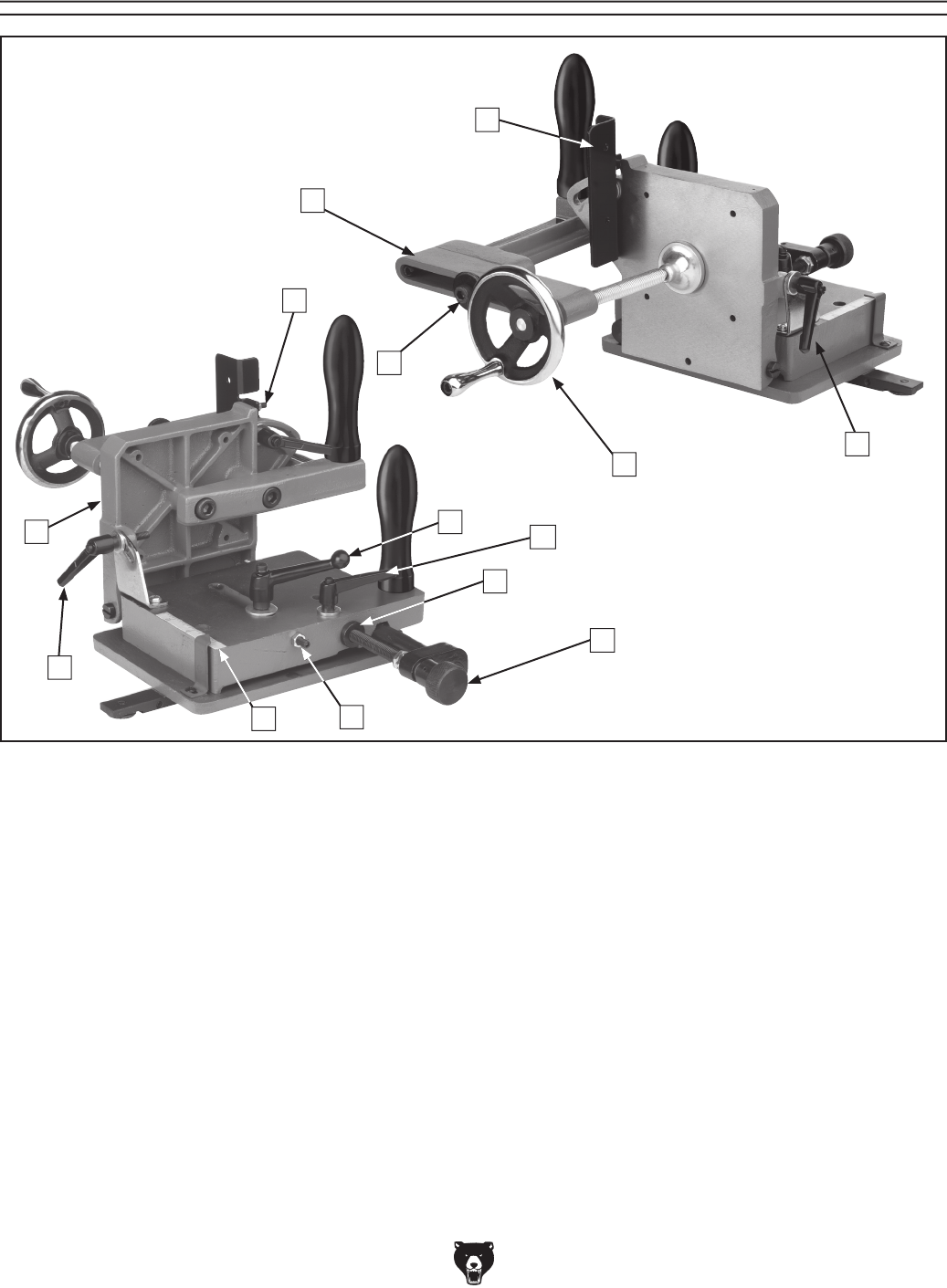
Identification
A. Adjustable Clamp Assembly
B. Back Stop
C. Clamp Slide Lock Bolt
D. Clamp Crank
E. Clamp Slide Lock Bolt
F. Back Stop Positive Stop
G. Base Lock Lever
H. Micro Adjustment Lock Knob
I. Major Adjustment Sleeve
J. Depth-of-Cut Micro Adjustment Knob
K. Depth-of-Cut Positive Stop
L. Depth-of-Cut Scale
M. Adjustment Lock Lever
N. Work Support Plate
J
I
K
B
C
D
GH
A
E
L
M
N
F
-4- H7583 Tenoning Jig
4. ALWAYS USE HEARING PROTECTION
WHEN OPERATING MACHINERY.
Machinery noise can cause permanent
hearing damage.
5. WEAR PROPER APPAREL. DO NOT
wear loose clothing, gloves, neckties, rings,
or jewelry which may get caught in moving
parts. Wear protective hair covering to con-
tain long hair and wear non-slip footwear.
6. NEVER OPERATE MACHINERY WHEN
TIRED, OR UNDER THE INFLUENCE OF
DRUGS OR ALCOHOL. Be mentally alert
at all times when running machinery.
1. READ THROUGH THE ENTIRE MANUAL
BEFORE STARTING MACHINERY.
Machinery presents serious injury hazards
to untrained users.
2. ALWAYS USE ANSI APPROVED
SAFETY GLASSES WHEN OPERATING
MACHINERY. Everyday eyeglasses only
have impact resistant lenses, they are
NOT safety glasses.
3. ALWAYS WEAR AN ANSI APPROVED
RESPIRATOR WHEN OPERATING
MACHINERY THAT PRODUCES DUST.
Wood dust is a carcinogen and can cause
cancer and severe respiratory illnesses.
For Your Own Safety, Read Instruction
Manual Before Operating this Machine
The purpose of safety symbols is to attract your attention to possible hazardous conditions. This
manual uses a series of symbols and signal words which are intended to convey the level of
importance of the safety messages. The progression of symbols is described below. Remember
that safety messages by themselves do not eliminate danger and are not a substitute for proper
accident prevention measures.
Indicates a potentially hazardous situation which, if not avoided,
MAY result in minor or moderate injury. It may also be used to
alert against unsafe practices.
Indicates a potentially hazardous situation which, if not avoided,
COULD result in death or serious injury.
Indicates an imminently hazardous situation which, if not avoided,
WILL result in death or serious injury.
This symbol is used to alert the user to useful information about
proper operation of the machine.
NOTICE
Safety Instructions for Machinery
SECTION 1: SAFETY

H7583 Tenoning Jig -5-
7. ONLY ALLOW TRAINED AND PROP-
ERLY SUPERVISED PERSONNEL TO
OPERATE MACHINERY. Make sure
operation instructions are safe and clearly
understood.
8. KEEP CHILDREN AND VISITORS AWAY.
Keep all children and visitors a safe dis-
tance from the work area.
9. MAKE WORKSHOP CHILD PROOF. Use
padlocks, master switches, and remove
start switch keys.
10. NEVER LEAVE WHEN MACHINE IS
RUNNING. Turn power OFF and allow all
moving parts to come to a complete stop
before leaving machine unattended.
11. DO NOT USE IN DANGEROUS
ENVIRONMENTS. DO NOT use machin-
ery in damp, wet locations, or where any
flammable or noxious fumes may exist.
12. KEEP WORK AREA CLEAN AND WELL
LIT. Clutter and dark shadows may cause
accidents.
13. USE A GROUNDED EXTENSION CORD
RATED FOR THE MACHINE AMPERAGE.
Undersized cords overheat and lose power.
Replace extension cords if they become
damaged. DO NOT use extension cords
for 220V machinery.
14.
ALWAYS DISCONNECT FROM POWER
SOURCE BEFORE SERVICING
MACHINERY. Make sure switch is in
OFF
position before reconnecting.
15. MAINTAIN MACHINERY WITH CARE.
Keep blades sharp and clean for best and
safest performance. Follow instructions for
lubricating and changing accessories.
16. MAKE SURE GUARDS ARE IN PLACE
AND WORK CORRECTLY BEFORE
USING MACHINERY.
Safety Instructions for Machinery
17. REMOVE ADJUSTING KEYS AND
WRENCHES. Make a habit of checking for
keys and adjusting wrenches before turn-
ing machinery ON.
18. CHECK FOR DAMAGED PARTS
BEFORE USING MACHINERY. Check
for binding and alignment of parts, broken
parts, part mounting, loose bolts, and any
other conditions that may affect machine
operation. Repair or replace damaged
parts.
19. USE RECOMMENDED ACCESSORIES.
Refer to the instruction manual for recom-
mended accessories. The use of improper
accessories may cause risk of injury.
20. DO NOT FORCE MACHINERY. Work at
the speed for which the machine or acces-
sory was designed.
21. SECURE WORKPIECE. Use clamps or
a vise to hold the workpiece when practi-
cal. A secured workpiece protects your
hands and frees both hands to operate the
machine.
22. DO NOT OVERREACH. Keep proper foot-
ing and balance at all times.
23. MANY MACHINES WILL EJECT THE
WORKPIECE TOWARD THE OPERATOR.
Know and avoid conditions that cause the
workpiece to "kickback."
24. ALWAYS LOCK MOBILE BASES
(IF USED) BEFORE OPERATING
MACHINERY.
25. BE AWARE THAT CERTAIN WOODS
MAY CAUSE AN ALLERGIC REACTION
in people and animals, especially when
exposed to fine dust. Make sure you
know what type of wood dust you will be
exposed to and always wear an approved
respirator.

-6- H7583 Tenoning Jig
Safety Instructions for the Tenoning Jig
7. ADJUSTING JIG. Unplug the table saw
before installing or adjusting the jig, saw, or
workpiece.
8. TENON MATERIAL SELECTION. Select
clean tenon locations that are low in mois-
ture content, and use workpieces that are
free of knots, staples, nails, and imbedded
stones. Run warped stock through a jointer
before you use the tenoning jig.
9. WORK AREA CLEANLINESS. Keep the
jig and table surface free of wood bits and
tools.
10. ACCESSORIES. Make sure other acces-
sories used on the table saw allow the
tenoning jig to operate freely with unbinding
travel.
11. BLADE GUARD. Reinstall the blade guard
and any other safety features on the table
saw when the tenoning jig is removed and
not used anymore.
12. EXPERIENCING DIFFICULTIES. If at any
time you are experiencing difficulties per-
forming the intended operation, stop using
the machine! Contact Tech Support at
(570) 546-9663.
1. OPERATION MANUAL. READ and
UNDERSTAND the operation manual for
the table saw before using this jig!
2. KICKBACK. Be familiar with kickback.
Kickback happens when the workpiece is
thrown towards the operator at a high rate
of speed. Until you have a clear under-
standing of kickback and how it occurs, DO
NOT operate the table saw!
3. REACHING OVER SAW BLADE. Never
reach behind or over the blade with either
hand while the saw is running. If kick-
back occurs while reaching over the blade,
hands or arms could be pulled into the
spinning saw blade.
4. OPERATOR POSITION. Never stand or
have any part of your body directly in-line
with the cutting path of the saw blade.
Avoid awkward operations and hand posi-
tions where a sudden slip could cause your
hand to move into the spinning saw blade.
5. SECURING WORKPIECE. ALWAYS
securely clamp the workpiece in the tenon-
ing jig, and MAKE SURE all fasteners are
tight before you make a cut.
6. JIG CONTROL. Hold both tenoning jig
handles firmly when cutting, NEVER hold
the jig with only one hand.
No list of safety guidelines can be complete.
Every shop environment is different. Always
consider safety first, as it applies to your
individual working conditions. Use this and
other machinery with caution and respect.
Failure to do so could result in serious per-
sonal injury, damage to equipment, or poor
work results.
Like all machines there is danger associ-
ated with the Model H7583. Accidents are
frequently caused by lack of familiarity or
failure to pay attention. Use this machine
with respect and caution to lessen the pos-
sibility of operator injury. If normal safety
precautions are overlooked or ignored, seri-
ous personal injury may occur.
H7583 Tenoning Jig -7-
The Model H7583 was carefully packed when it
left our warehouse. If you discover the machine
is damaged after you have signed for delivery,
please immediately call Customer Service at
(570) 546-9663 for advice.
Save the containers and all packing materials for
possible inspection by the carrier or its agent.
Otherwise, filing a freight claim can be difficult.
When you are completely satisfied with the con-
dition of your shipment, you should inventory the
contents.
Wear safety glasses dur-
ing the entire set up pro-
cess!
This jig presents seri-
ous injury hazards to
untrained users. Read
through this entire man-
ual to become familiar
with the controls and
operations before using
this jig!
Unpacking
Set Up Safety
SECTION 2: SET UP
Inventory
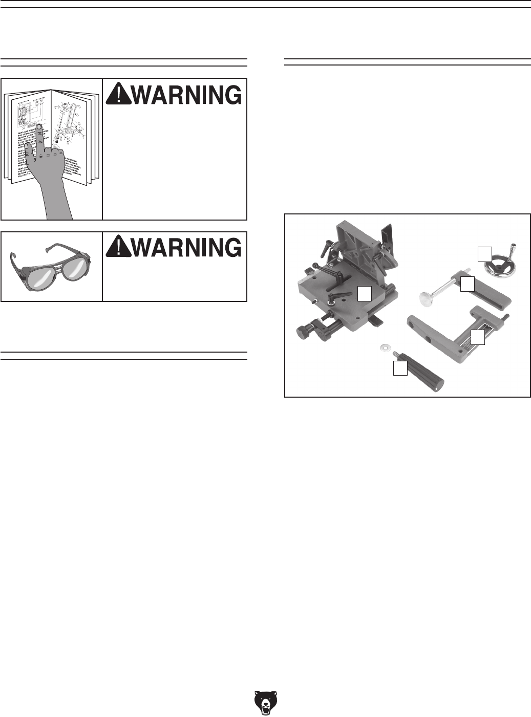
After all the parts have been removed from the
two boxes, you should have the following items:
Box 1: (Figure 1) Qty
A. Work Plate Assembly and Base ................. 1
B. Clamp Assembly ........................................ 1
C. Clamp Handle ............................................. 1
D. Clamp Arm ................................................. 1
E. Push Handles w/Flat Washer ..................... 2
Figure 1. Tenoning jig inventory.
A
C
B
D
E
Hardware and Tools Qty
• Lock Washer 10mm ................................... 2
• Fender Washer 8mm ................................. 1
• Cap Screw M8-1.25 x 50mm ..................... 1
• Cap Screw M10-1.5 x 25mm ..................... 1
• Cap Screw M10-1.5 x 20mm ..................... 1
• Hex Wrenches 2.5, 3, 4, 6, 8mm ..........1 Ea
-8- H7583 Tenoning Jig
The unpainted surfaces are coated with a waxy
oil to protect them from corrosion during ship-
ment. Remove this protective coating with a sol-
vent cleaner or citrus-based degreaser such as
Grizzly’s G7895 Degreaser. To clean thoroughly,
some parts may need to be removed. For opti-
mum performance from your machine, make
sure you clean all moving parts or sliding
contact surfaces that are coated. Avoid chlo-
rine-based solvents, such as acetone or brake
parts cleaner, as they may damage painted sur-
faces should they come in contact. Always follow
the manufacturer’s instructions when using any
type of cleaning product.
Clean Up
Gasoline and petroleum
products have low flash
points and could cause
an explosion or fire if
used to clean machinery.
DO NOT use gasoline or
petroleum products to
clean the machinery.
Many of the solvents
commonly used to clean
machinery can be toxic
when inhaled or ingest-
ed. Lack of ventilation
while using these sol-
vents could cause seri-
ous personal health risks
or fire. Take precautions
from this hazard by only
using cleaning solvents
in a well ventilated area.
Always disconnect power
to the machine before
performing adjustments
or maintenance. Failure
to do this may result in
serious personal injury.
The Model H7583 Tenoning Jig is made to oper-
ate in a 3⁄8" x 3⁄4" miter T-slot. If the tenoning jig
operates on a worn or mis-adjusted saw, tenon-
ing results will be poor. Review the following list to
make sure you prepare your saw correctly.
• Table Saw Operation: Make sure that you
read and understand your table saw instruc-
tion manual, and take all safety precautions.
• Saw Blades: Make sure that your saw
blades have no runout and that the teeth are
sharp.
• Saw Adjustments: Make sure that your
table saw blade is perpendicular to the table
and parallel with the miter slots.
• Miter Slot and Table: Make sure the table-
saw miter slots are 3⁄8" x 3⁄4", and the table is
free of burrs and interferences that may bind
the tenoning jig.
• Lighting: Make sure the top of your table
saw has adequate lighting, so the tenoning
jig and workpiece is illuminated without shad-
ows.
Table Saw
Preparation
DO NOT remove the washer from the miter
bar of the tenoning jig. Removal of the
washer will allow the tenoning jig to come
loose during a kickback, possibly causing a
serious personal injury.
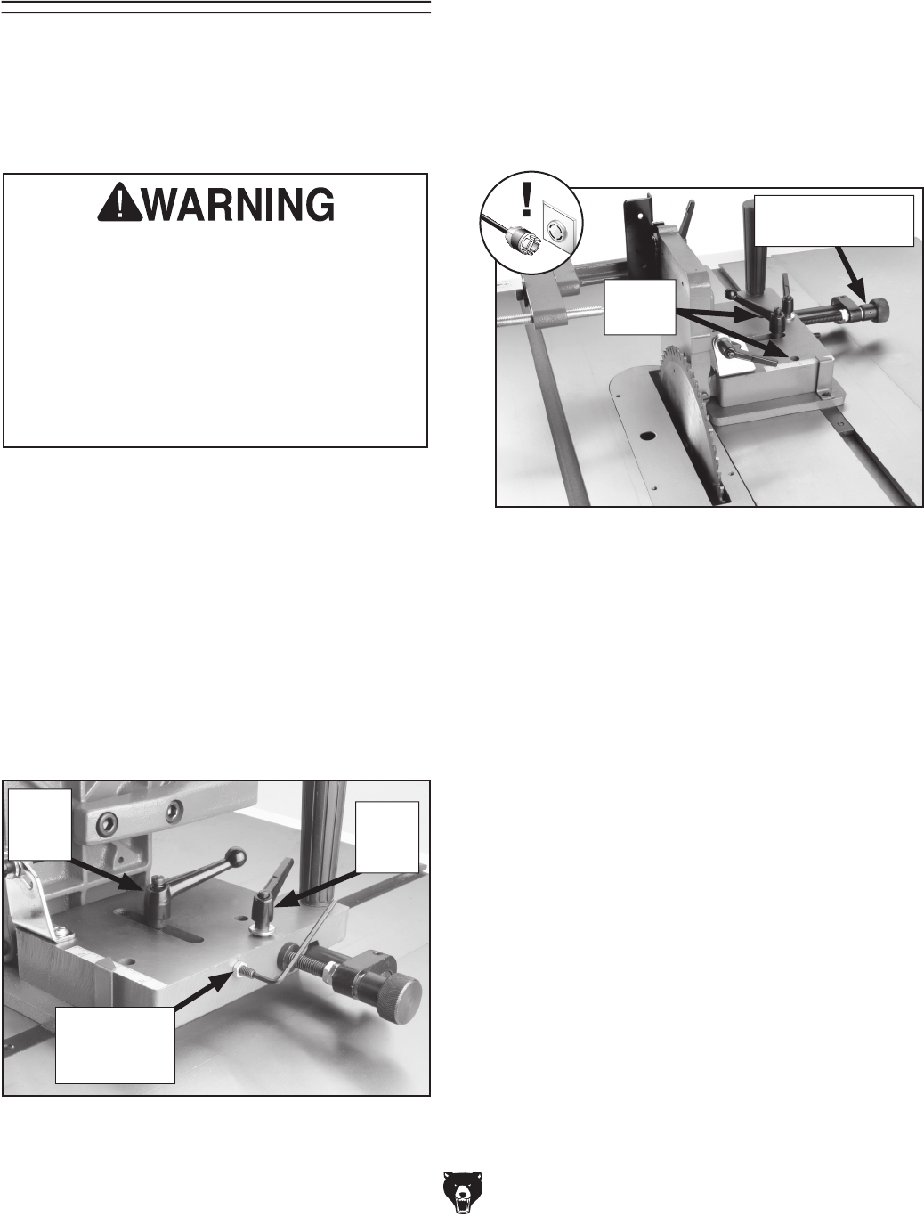
H7583 Tenoning Jig -9-
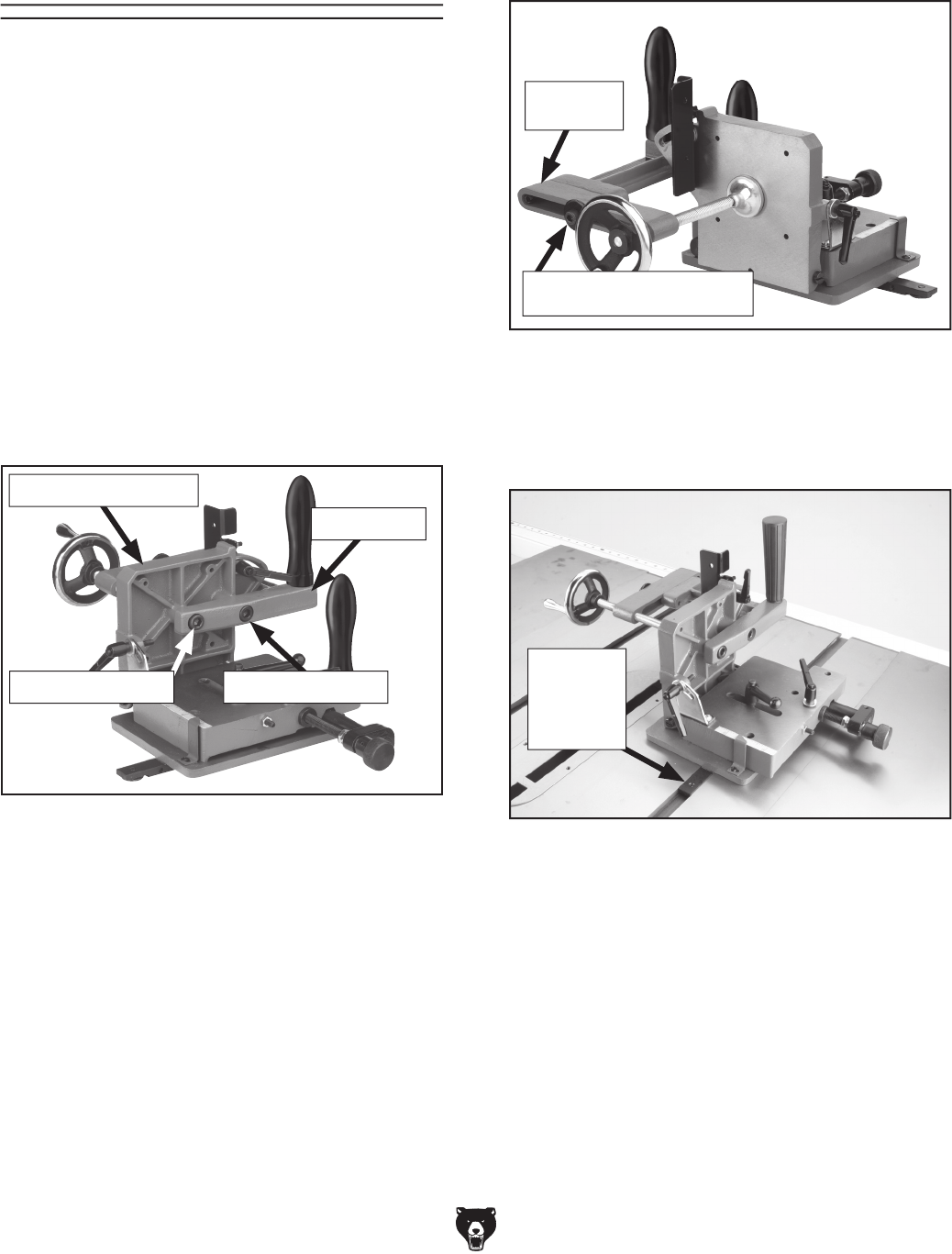
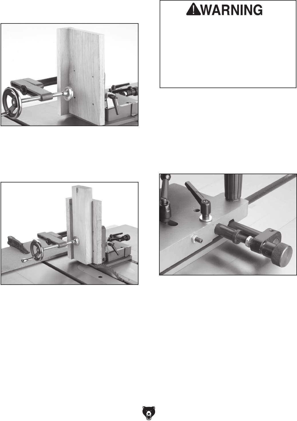
Figure 2. Partial assembly.
In this procedure you will assemble the tenoning
jig. The guide bar is initially in position on the jig
for jig use on a right-tilting table saw. If you need
to use the jig on a left-tilting table saw, go to Jig
Setup for a Left-Tilt Table Saw on Page 10.
To set up the jig for a right tilt table saw:
1. Attach the clamp arm to the work support
plate with the cap screws and lock washers
as shown in Figure 2.
Note: The cap screws are different lengths
and must go into the correct holes. See
Figure 2 for the long (M10-1.5 x 25mm), and
short cap screw (M10-1.5 x 20mm) hole loca-
tions.
Jig Setup for a
Right-Tilt Table Saw
Figure 4. Installed jig.
5. Insert the jig guide bar into the miter slot in
the table-saw table (Figure 4), and perform
Guide Bar Adjustment on Page 11.
Guide Bar
Inserted
Into the
Miter Slot
Work Support Plate
Clamp
Assembly
Clamp Arm
Short Cap Screw
Long Cap Screw
2. Install both handles into the jig as shown in
Figure 2.
3. Slide the handwheel onto the end of the
clamp assembly threaded shaft and secure it
with the setscrew in the handwheel hub.
4. Attach the clamp assembly to the clamp arm
with an M8-1.25 x 50 cap screw and the 8mm
fender washer (see Figure 3).
Figure 3. Completed assembly.
M8-1.25 x 50 Cap Screw
and Oversized Washer
-10- H7583 Tenoning Jig
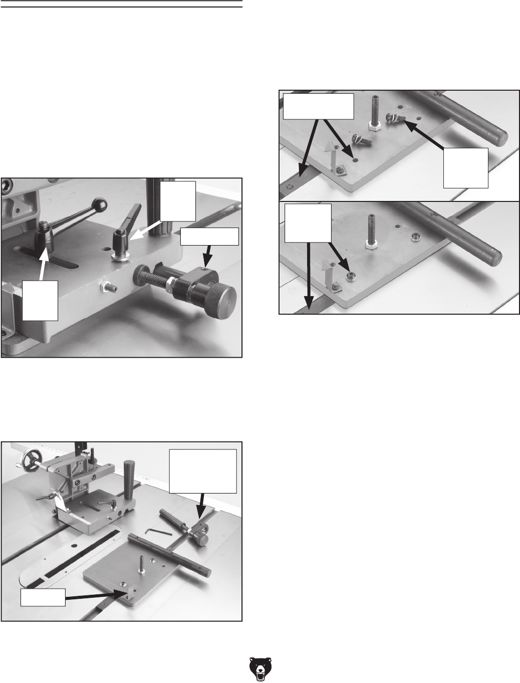
Figure 7. Guide bar locations.
Button
Head
Screw
Left-Tilt
Saw
Location
Right-Tilt
Saw Location
Jig Setup for a Left-
Tilt Table Saw
In this procedure you will partially dissemble the
tenoning jig and reassemble it for use on a left-tilt-
ing table saw.
To set up the jig for a left tilt table saw:
1. Insert the jig guide bar into the miter slot in
the table-saw table.
2. Loosen the small lock lever and remove the
large lock lever (see Figure 5).
7. Reposition the guide bar to the other set of
holes and reinstall the button head screws
(see Figure 7).
8. Reassemble the jig in reverse order.
9. Go to Page 11, and perform the Guide Bar
Adjustment.
Figure 5. Assembled jig.
Small
Lock
Lever
Large
Lock
Lever
Set Screw
3. Loosen the pointer screw, and turn the point-
er 90º so the jig assembly and base can be
separated (see Figure 6).
Figure 6. Jig base on a right-tilt table saw.
Pointer
4. Use the 3mm hex wrench to loosen the set-
screw shown in Figure 5.
5. Slide the micro adjustment assembly out of
the jig, and lift the jig assembly from the base
as shown in Figure 6.
6. Use the 4mm hex wrench to loosen and
remove the two button head screws (Figure
7) that hold the guide bar to the base.
Micro
Adjustment
Assembly
H7583 Tenoning Jig -11-
Figure 8. Miter slot guide bar.
Guide Bar
In this procedure you will adjust the guide bar so
there is minimal play between the miter slot and
guide bar. The jig must slide in the miter slot with-
out side-to-side play or tilt.
To adjust the guide bar:
1. Unplug the table saw!
2. Set the guide bar in the left hand miter slot
and slide it back and forth to see if there is
any play.
—If the guide bar fits snug, but slides free-
ly in the miter slot, no adjustment is
required. Perform the Work Support Plate
Adjustment on this page.
—If play exists, continue with the following
steps.
3. Remove the jig and set it on a table upside
down as shown in Figure 8.
Guide Bar
Adjustment
Side Play
Setscrews
4. Use a 2.5mm hex wrench and adjust the side
play setscrews shown in Figure 8 to remove
or gain side-to-side play.
5. Reinsert the jig into the miter slot and repeat
Step 2.
Figure 9. Machinist's square placement.
Positive
Stop
Setscrew
In this procedure you will adjust the work sup-
port plate so it is perpendicular to the table. Then
you will set the positive stop so the plate can be
quickly returned to the perpendicular position
after angle cutting.
To adjust the work support plate:
1. Unplug the table saw!
2. Insert the jig and guide bar into the left-hand
miter slot and slide the jig into position close
to the saw blade.
3. Position a machinist’s square against the
table and the work support plate as shown in
Figure 9.
Work Support Plate
Adjustment
Machinist’s
Square
Lock
Lever
4. Loosen the lock lever and position the work
support plate perpendicular to the table.
Tighten the lock lever when perpendicular.
5. Turn the positive stop setscrew (Figure 9)
inward with a 3mm hex wrench until it stops.
The positive stop is now set for quick perpen-
dicular positioning of the work support table.
-12- H7583 Tenoning Jig
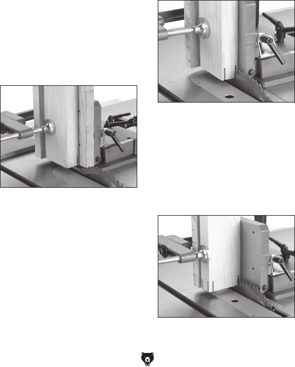
Figure 10. Blade clearance adjustment.
Figure 11. Blade parallelism.
Jam Nut
and Positive
Stop
In this procedure you will adjust the work support
plate parallel and 1⁄8" away from the edge of the
saw blade. Then set the positive stop so the work
support plate can be quickly returned to this posi-
tion after cutting various thicknesses.
Blade Clearance
Adjustment
MAKE SURE the blade clearance is adjusted
correctly! DO NOT adjust the work support
plate any closer than 1⁄8" from the saw blade.
If the blade contacts the work support plate,
severe injury may occur. If the blade must
be closer than 1⁄8" for special circumstances,
fasten a block of wood through the holes in
the work support plate to prevent the saw
blade from contacting the jig.
Large
Lock
Lever
Small
Lock
Lever
5. Slide the work support plate against the saw
blade and tighten the large lock lever.
6. Observe the contact of the saw blade and the
work support plate as shown in Figure 11.
—If the work support plate is parallel with the
blade, go to Step 10.
—If the work support plate is not parallel with
the blade, go to Step 7.
To adjust the blade clearance:
1. Unplug the table saw!
2. Make sure the saw blade is perpendicular to
the table and parallel with the miter slots.
3. Loosen the jam nut and the positive stop
approximately 3-4 turns (see Figure 10).
4. Loosen the large and small lock levers shown
in Figure 10.
7. Loosen the large lock lever and turn the
micro-adjustment knob to align the access
holes (Figure 11) with the guide bar screws.
8. Insert a 4mm hex wrench through the access
holes and loosen the two guide bar screws.
9. Position the work support plate so it is parallel
to the saw blade and retighten the two guide
bar screws.
10. Move the work support plate 1⁄8" away from
the edge of the saw blade and tighten the
large lock lever.
Access
Holes
Micro-Adjustment
Knob
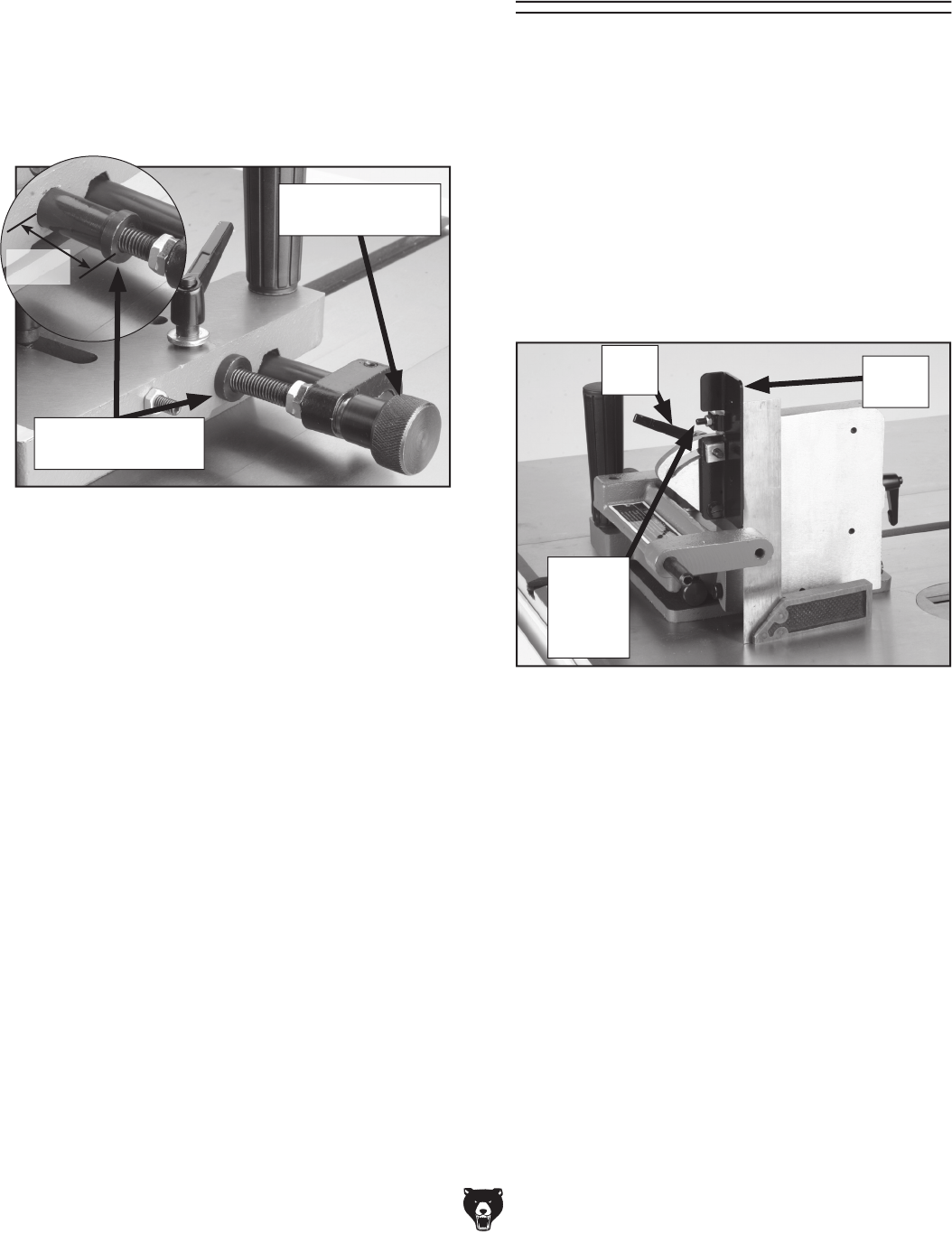
H7583 Tenoning Jig -13-
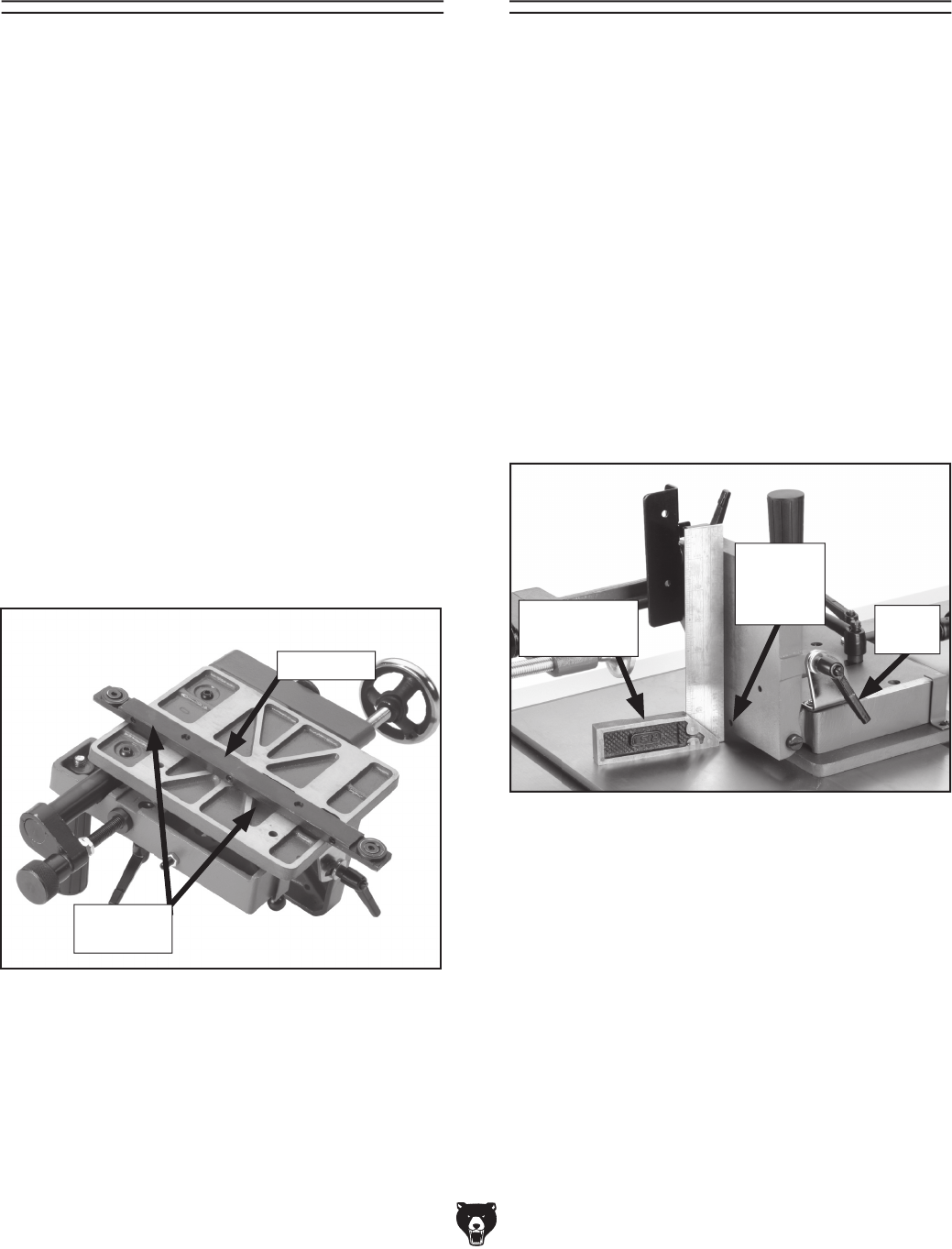
10. Rotate the micro-adjustment knob until the
major adjustment sleeve extends 11⁄2" out of
the jig, or approximately halfway between the
knob and the side of the jig (see Figure 12).
Note: The major adjustment sleeve allows
for quick adjustment of the jig positioning.
The micro adjustment knob fine tunes the
quick adjustment that was made.
Figure 12. Setting major adjustment sleeve.
11. Tighten the small lock lever and use a 3mm
hex wrench to turn the positive stop setscrew
inward until it stops (see Figure 10).
Note: The positive stop prevents the work
support plate from sliding into the saw blade.
12. Tighten the jam nut and make sure the work
support plate stops an 1⁄8" away from the
edge of the saw blade.
13. Loosen the pointer screw and reposition the
pointer to “0” on the scale.
11⁄2"
Micro-Adjustment
Knob
Major Adjustment
Sleeve
Figure 13. Machinist’s square location.
Jam
Nut and
Positive
Stop
In this procedure you will adjust the back stop
perpendicular to the table. Then set the positive
stop so the back stop can be returned to the per-
pendicular position after angle cutting.
To adjust the back stop, do these steps:
1. Unplug the table saw!
2. Place the jig into the miter slot. Position a
machinist’s square against the back stop as
shown in Figure 13.
Back Stop
Adjustment
Lock
Lever Back
Stop
3. Loosen the lock lever. Position the back stop
perpendicular to the table, and tighten the
lock lever.
4. Loosen the positive stop jam nut with an 8mm
wrench. Use a 2.5mm hex wrench to turn the
setscrew inward until it stops, and tighten the
jam nut.
-14- H7583 Tenoning Jig
Damage to your eyes, lungs, and ears could
result from using this jig without proper
protective gear. Always wear safety glasses,
a respirator, and hearing protection when
operating machinery.
Loose hair and cloth-
ing could get caught in
machinery and cause seri-
ous personal injury. Keep
loose clothing and long
hair away from moving
machinery.
Operation Safety
SECTION 3: OPERATIONS
NOTICE
If you have never used this type of jig
before, WE STRONGLY RECOMMEND that
you read books, trade magazines, or get
formal training before beginning any proj-
ects. Regardless of the content in this sec-
tion, Grizzly Industrial will not be held liable
for accidents caused by lack of training.
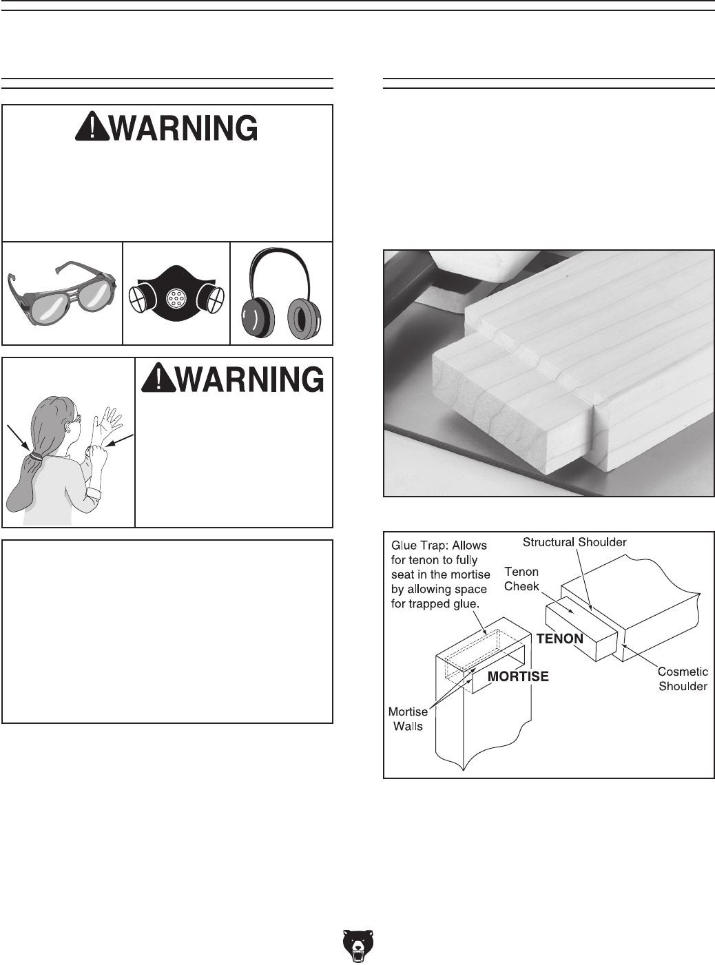
Overview
Your new tenoning jig features three positive
stops that allow for fast and accurate positioning
of the back stop angle, work support angle, and
work support distance from the blade. This jig is
designed to make tenon cheek cuts only; howev-
er, you can make many special variations to the
basic tenon that is shown in Figures 14 & 15.
Figure 14. Basic tenon.
Figure 15. Typical mortise and tenon.
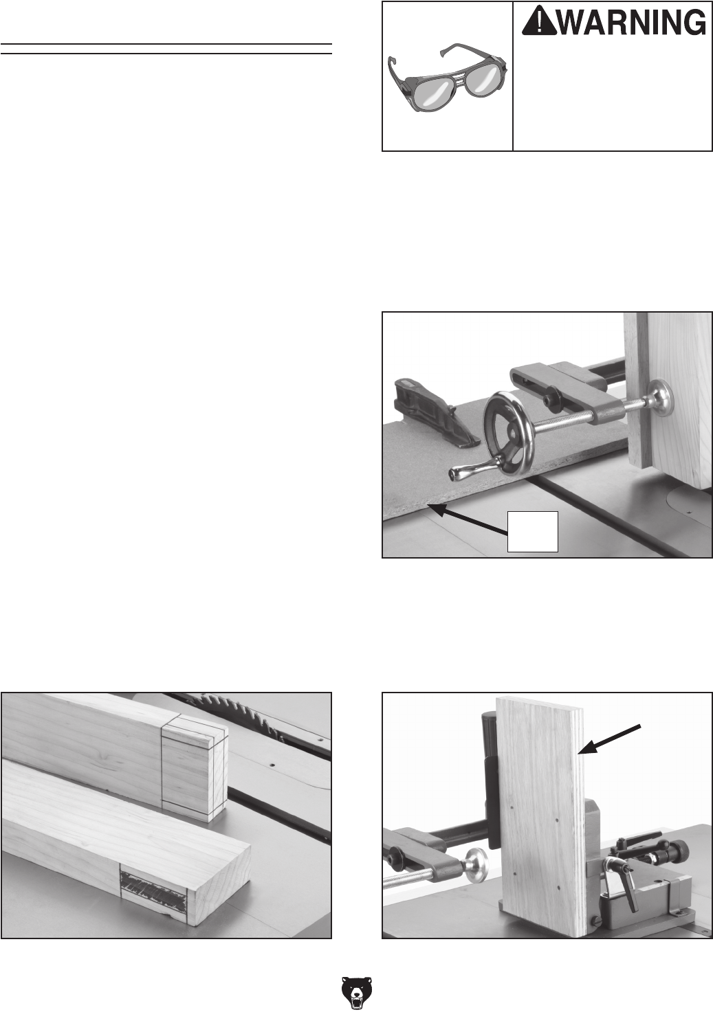
H7583 Tenoning Jig -15-
2. Plane a wood base stop to the thickness of
the tenoning jig base, and mount it to the
front of the table saw as shown in Figure 17.
The base stop prevents cut off pieces getting
trapped between the saw blade and the work
support plate.
Basic Tenon Cutting
WEAR your safety glass-
es when you perform
any assembly, operation,
and maintenance. Failure
to comply may result in
serious personal injury.
Your new tenoning jig is designed to make tenon
cheek cuts only, and generally, cheek cuts are
made before the shoulder cuts. This procedure
will guide you through three parts; A, B, and C to
show you how to cut your first basic tenon.
A. Preparing the tenoning jig and
workpiece:
Note: The shoulder cuts and angle cuts are made
on the table saw with the miter gauge.
1. Select your mortise and tenon joints, and
draw the cutting lines as shown in Figure 16.
Make sure to account for the thickness of the
saw blade.
—For the strongest joints, select joint loca-
tions that are free of knots and twists.
—Tenons need structural and cosmetic
shoulders to hide gaps that may occur as
the wood shrinks.
—When joining parts of the same thickness,
make the tenon the same thickness as the
tenon walls.
—When joining parts where one piece is
larger than the other, make the tenon as
thick as possible.
—Make the mortise 1⁄8" deeper than the tenon
to allow for the glue to squeeze out.
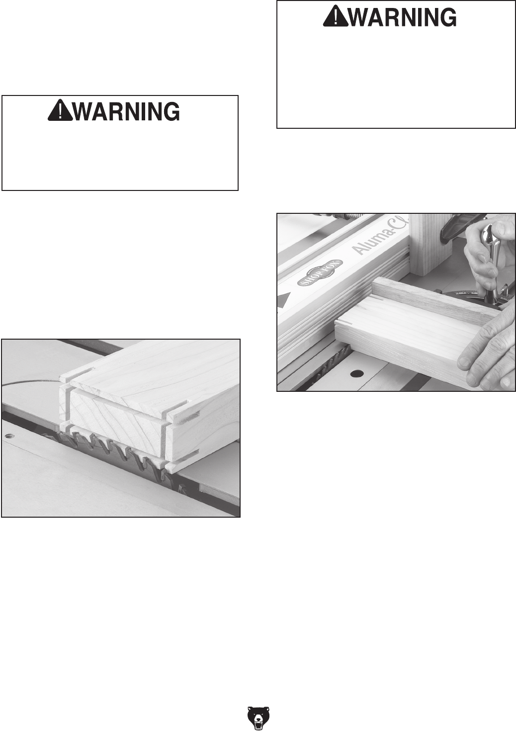
Figure 16. Tenon layout.
Figure 17. Base stop attached to the table saw.
Base
Stop
3. Cut a wooden spacer block the same thick-
ness as the tenon plus the saw blade. Screw
through the holes in the work support plate to
attach the spacer block (see Figure 18).
Figure 18. Work support spacer block.
-16- H7583 Tenoning Jig
MAKE SURE the blade clearance is adjusted
correctly! DO NOT adjust the work support
plate any closer than 1⁄8" from the saw blade.
If the blade contacts the work support plate,
severe injury may occur. If the blade must
be closer than 1⁄8" for special circumstances,
fasten a block of wood through the holes in
the work support plate to prevent the saw
blade from contacting the jig.
5. Slide the jig back to the base stop, place the
workpiece on the base stop, and clamp the
workpiece against spacer block and back
stop as shown in Figure 20.
4. Cut a back stop backup board and screw it to
the back stop as shown in Figure 19.
Figure 19. Back stop backup board.
6. Slide the jig up next to the saw blade, and use
the major and micro adjustments (Figure 21)
to line up the layout lines on the workpiece
with the saw blade.
Note: The major adjustment sleeve allows
for quick adjustment of the jig positioning,
and the micro adjustment knob fine tunes the
quick adjustment that was made.
Figure 20. Clamping the workpiece.
Figure 21. Major adjustment sleeve and micro
adjustment knob.
H7583 Tenoning Jig -17-
Figure 22. First structural cheek cut.
B. Cutting Tenon Cheeks:
The tenon uses two styles of cheeks, structural
and cosmetic. In this procedure you will cut the
structural cheeks first, then the cosmetic cheeks.
1. Make sure all jig fixtures, lock levers, and
setscrews are tight and correctly adjusted.
2. Plug the table saw power cord into the power
supply and turn the saw ON.
3. Grasp the jig firmly and slowly slide the jig
toward the saw blade and make the first
structural-cheek cut (see Figure 22). DO
NOT slide the jig quickly toward the saw
blade or the jig can raise up and away from
the table.
4. When the blade exits the workpiece, carefully
and slowly pull the jig back past the blade to
the base stop and turn OFF the saw.
7. Rotate the workpiece so you can now cut the
two cosmetic cheeks.
8. Power up the saw, and make the remain-
ing cosmetic cheek cuts the same way as in
Steps 3 & 4, unplug and turn OFF the saw
(see Figure 24).
Note: For cosmetic cheek cuts, merely rotate
the workpiece 180º instead of using the
spacer block. Cosmetic cheek cut positioning
is not as critical for structural cheek cuts.
5. Remove the spacer block from the work sup-
port base and re-clamp the workpiece.
6. Turn the saw ON and make the second cut
as shown in Figure 23 and turn OFF the
saw.
Figure 23. Second structural cheek cut.
Figure 24. Third and fourth
cosmetic cheek cuts.
-18- H7583 Tenoning Jig
Figure 26. Cutting the shoulder.
C. Cutting Tenon Shoulders:
The final set of cuts are two structural shoulder
cuts and two cosmetic shoulder cuts. In this
procedure you will complete the tenon by using
the table saw fence, a stop block clamped to the
fence, the saw miter gauge, and the base stop.
ALWAYS use a cross-cut saw blade when
making tenon shoulder cuts. Otherwise,
the saw can grab the workpiece causing
machine damage and severe personal
injury!
ALWAYS clamp the fence stop block in
front of the saw blade so the workpiece
will not be trapped between the saw blade
and the fence. When the work piece begins
to be cut, the workpiece must be free from
the stop block. Ignoring this warning may
cause kickback and severe personal injury!
1. Remove the jig from the table saw install a
cross-cut saw blade and the miter gauge.
2. Adjust the saw blade height to cut the tenon
structural shoulder as shown in Figure 25.
Note: When cutting tenon shoulders, avoid
nicking the cheeks of the tenon. Nicks in the
tenons greatly weaken them.
3. Clamp a stop block to the fence face before the
saw blade (Figure 26) and adjust the fence to
cut the structural shoulder. Remember, take
into account the thickness of the blade.
Figure 25. Adjusting the saw blade height.
4. Position the workpiece against the miter
gauge (equipped with a backing board) and
the fence stop block.
5. Turn the saw ON, and carefully and slowly
push the miter gauge to cut the structural
shoulder as shown in Figure 26.
6. Turn the saw OFF, and when the blade is
stopped, remove the cut-off piece of wood.
7. Repeat Steps 2-6 to cut the remaining shoul-
ders.

H7583 Tenoning Jig -19-
Always disconnect power
to the machine before
performing maintenance.
Failure to do this may
result in serious person-
al injury.
Lubrication
Cleaning the Model H7583 is relatively easy.
Vacuum excess wood chips and sawdust, and
wipe off the remaining dust with a dry cloth. If any
resin has built up, use a resin dissolving cleaner
to remove it. Treat all unpainted cast iron and
steel with a non-staining lubricant after cleaning.
Cleaning
SECTION 4: MAINTENANCE
Protect the unpainted cast iron surfaces on the jig
by wiping it clean after every use—this ensures
moisture from wood dust does not remain on bare
metal surfaces.
Keep unpainted cast iron rust-free with regular
applications of products like G96® Gun Treatment,
SLIPIT®, or Boeshield® T-9.
Unpainted Cast Iron
For optimum performance from your jig, follow this
maintenance schedule and refer to any specific
instructions given in this section.
Daily Check:
• Loose mounting bolts, levers, setscrews and
jam nuts.
• Worn or damaged parts.
• Rust or corrosion on threads and machined
surfaces.
• Any other unsafe condition.
Schedule
For setscrew and lock lever threads, an occa-
sional application of light machine oil is all that
is necessary. Before applying lubricant, clean off
sawdust.
Your goal is to achieve adequate lubrication. Too
much lubrication will attract dirt and sawdust.
Various parts of your jig could lose their freedom
of movement as a result.
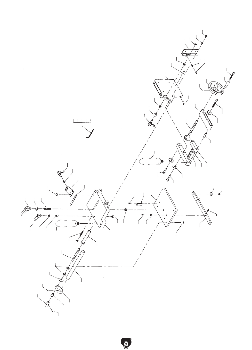
-20- H7583 Tenoning Jig
Parts List and Breakdown

H7583 Tenoning Jig -21-
Parts List
REF PART # DESCRIPTION REF PART # DESCRIPTION
1 PH7583001 LOCK LEVER M8-1.25 34-3 PH7583034-3 FLAT HD SCR 1/4-28 X 5/16
2 PW01M FLAT WASHER 8MM 35 PH7583007 HANDLE M10-1.5 X 20
3 PH7583003 STUD M8-1.25 X 55 36 PSB64M CAP SCREW M10-1.5 X 25
4 PH7583004 LOCK LEVER M6-1 X 28 36A PSB61M CAP SCREW M10-1.5 X 20
5 PW03M FLAT WASHER 6MM 37 PLW06M LOCK WASHER 10MM
6 PH7583006 LOCK BUSHING 38 PH7583038 CLAMP BRACKET
7 PH7583007 HANDLE M10-1.5 X 20 39 PH7583039 WARNING LABEL
8 PH7583008 KNURLED KNOB 10MM PINNED 40 PH7583040 SPECIAL NAIL 4 X 8
9 PRP42M ROLL PIN 3 X 20 41 PH7583041 ROLL PIN 3/8 X 2"
10 PH7583010 BUSHING 42 PH7583042 CLAMP ARM
11 PH7583011 BRACKET 43 PW01M FLAT WASHER 8MM
12 PSS01M SET SCREW M6-1 X 10 44 PSB05M CAP SCREW M8-1.25 X 50
13 PH7583013 NYLON WASHER 10MM 45 PH7583045 HANDWHEEL
14 PN02M HEX NUT M10-1.5 46 PH7583046 HANDWHEEL HANDLE
15 PH7583015 SHAFT 46-1 PH7583046-1 SPECIAL SCREW M6-1 X 55
16 PH7583016 GUIDE BUSHING 47 PSS03M SET SCREW M6-1 X 8
17 PH7583017 GUIDE ROD 48 PH7583048 CLAMP SCREW
18 PSS85M SET SCREW M6-1 X 45 49 PH7583004 LOCK LEVER M6-1 X 28
19 PN01M HEX NUT M6-1 49-1 PH7583006 LOCK BUSHING
20 PH7583020 SLIDE 50 PW03M FLAT WASHER 6MM
21 PH7583021 SCALE 51 PH7583051 VERTICAL TABLE
22 PS09M PHLP HD SCR M5-.8 X 10 54 PH7583054 SHOULDER SCREW M6 X 20
23 PH7583004 LOCK LEVER M6-1 X 28 55 PSS12M SET SCREW M6-1 X 25
24 PW03M FLAT WASHER 6MM 56 PW03M FLAT WASHER 6MM
25 PH7583025 BRACKET 57 PH7583057 STOP
26 PH7583026 BUSHING 57-1 PN06M HEX NUT M5-.8
27 PN03M HEX NUT M8-1.25 57-2 PSS57M SET SCREW M5-.8 X 20
28 PS07M PHLP HD SCR M4-.7 X 8 58 PSN02M SQUARE NUT M6-1
29 PH7583029 POINTER 59 PH7583059 SPECIAL SLOT SCREW M5-.8 X 10
30 PSBS05M BUTTON HD CAP SCR M6-1 X 20 59-1 PH7583059-1 WAVY WASHER 6MM
31 PLW03M LOCK WASHER 6MM 65 PAW03M HEX WRENCH 3MM
32 PH7583032 BASE 66 PAW04M HEX WRENCH 4MM
33 PSBS05M BUTTON HD CAP SCR M6-1 X 20 67 PAW06M HEX WRENCH 6MM
34 PH7583034 GUIDE BAR 68 PAW08M HEX WRENCH 8MM
34-1 PH7583034-1 PILOT SET SCREW M5-.8 X 16 69 PAW02.5M HEX WRENCH 2.5MM
34-2 PH7583034-2 PLATE

-22- H7583 Tenoning Jig
Grizzly Industrial, Inc. warrants every product it sells for a period of 1 year to the original purchaser from
the date of purchase. This warranty does not apply to defects due directly or indirectly to misuse, abuse,
negligence, accidents, repairs or alterations or lack of maintenance. This is Grizzly’s sole written warranty
and any and all warranties that may be implied by law, including any merchantability or fitness, for any par-
ticular purpose, are hereby limited to the duration of this written warranty. We do not warrant or represent
that the merchandise complies with the provisions of any law or acts unless the manufacturer so warrants.
In no event shall Grizzly’s liability under this warranty exceed the purchase price paid for the product and
any legal actions brought against Grizzly shall be tried in the State of Washington, County of Whatcom.
We shall in no event be liable for death, injuries to persons or property or for incidental, contingent, special,
or consequential damages arising from the use of our products.
To take advantage of this warranty, contact us by mail or phone and give us all the details. We will then
issue you a “Return Number,’’ which must be clearly posted on the outside as well as the inside of the
carton. We will not accept any item back without this number. Proof of purchase must accompany the
merchandise.
The manufacturers reserve the right to change specifications at any time because they constantly strive to
achieve better quality equipment. We make every effort to ensure that our products meet high quality and
durability standards and we hope you never need to use this warranty.
Please feel free to write or call us if you have any questions about the machine or the manual.
Thank you again for your business and continued support. We hope to serve you again soon.
WARRANTY AND RETURNS

CUT ALONG DOTTED LINE
Name _____________________________________________________________________________
Street _____________________________________________________________________________
City _______________________ State _________________________ Zip _____________________
Phone # ____________________ Email ________________________ Invoice # _________________
Model # ____________________ Order # _______________________ Serial # __________________
WARRANTY CARD
The following information is given on a voluntary basis. It will be used for marketing purposes to help us develop
better products and services. Of course, all information is strictly confidential.
1. How did you learn about us?
____ Advertisement ____ Friend ____ Catalog
____ Card Deck ____ Website ____ Other:
2. Which of the following magazines do you subscribe to?
3. What is your annual household income?
____ $20,000-$29,000 ____ $30,000-$39,000 ____ $40,000-$49,000
____ $50,000-$59,000 ____ $60,000-$69,000 ____ $70,000+
4. What is your age group?
____ 20-29 ____ 30-39 ____ 40-49
____ 50-59 ____ 60-69 ____ 70+
5. How long have you been a woodworker/metalworker?
____ 0-2 Years ____ 2-8 Years ____ 8-20 Years ____ 20+ Years
6. How many of your machines or tools are Grizzly?
____ 0-2 ____ 3-5 ____ 6-9 ____ 10+
7. Do you think your machine represents a good value? _____Yes _____No
8. Would you recommend Grizzly Industrial to a friend? _____Yes _____No
9. Would you allow us to use your name as a reference for Grizzly customers in your area?
Note: We never use names more than 3 times. _____Yes _____No
10. Comments: _____________________________________________________________________
_________________________________________________________________________________
_________________________________________________________________________________
_________________________________________________________________________________
____ Cabinet Maker
____ Family Handyman
____ Hand Loader
____ Handy
____ Home Shop Machinist
____ Journal of Light Cont.
____ Live Steam
____ Model Airplane News
____ Modeltec
____ Old House Journal
____ Popular Mechanics
____ Popular Science
____ Popular Woodworking
____ Practical Homeowner
____ Precision Shooter
____ Projects in Metal
____ RC Modeler
____ Rifle
____ Shop Notes
____ Shotgun News
____ Today’s Homeowner
____ Wood
____ Wooden Boat
____ Woodshop News
____ Woodsmith
____ Woodwork
____ Woodworker West
____ Woodworker’s Journal
____ Other:

TAPE ALONG EDGES--PLEASE DO NOT STAPLE
FOLD ALONG DOTTED LINE
FOLD ALONG DOTTED LINE
GRIZZLY INDUSTRIAL, INC.
P.O. BOX 2069
BELLINGHAM, WA 98227-2069
Place
Stamp
Here
Name_______________________________
Street_______________________________
City______________State______Zip______
Send a Grizzly Catalog to a friend:

Buy Direct and Save with Grizzly® – Trusted, Proven and a Great Value!
-OR-
• SECURE ORDERING
• ORDERS SHIPPED WITHIN 24 HOURS
• E-MAIL RESPONSE WITHIN ONE HOUR
Visit Our Website Today And Discover Why
Grizzly® Is The Industry Leader!
Call Today For A
FREE
Full Color Catalog
