User Manual
For questions or help with this product contact Tech Support at (570) 546-9663 or techsupport@grizzly.com
MODEL T25448/T25449
DUST COLLECTOR
REMOTE SWITCH
INSTRUCTIONS
COPYRIGHT © FEBRUARY, 2013 BY GRIZZLY INDUSTRIAL, INC.
NO PORTION OF THIS MANUAL MAY BE REPRODUCED IN ANY SHAPE
OR FORM WITHOUT THE WRITTEN APPROVAL OF GRIZZLY INDUSTRIAL, INC.
FOR MODELS MANUFACTURED SINCE 8/13 #TS15583 PRINTED IN TAIWAN
Introduction
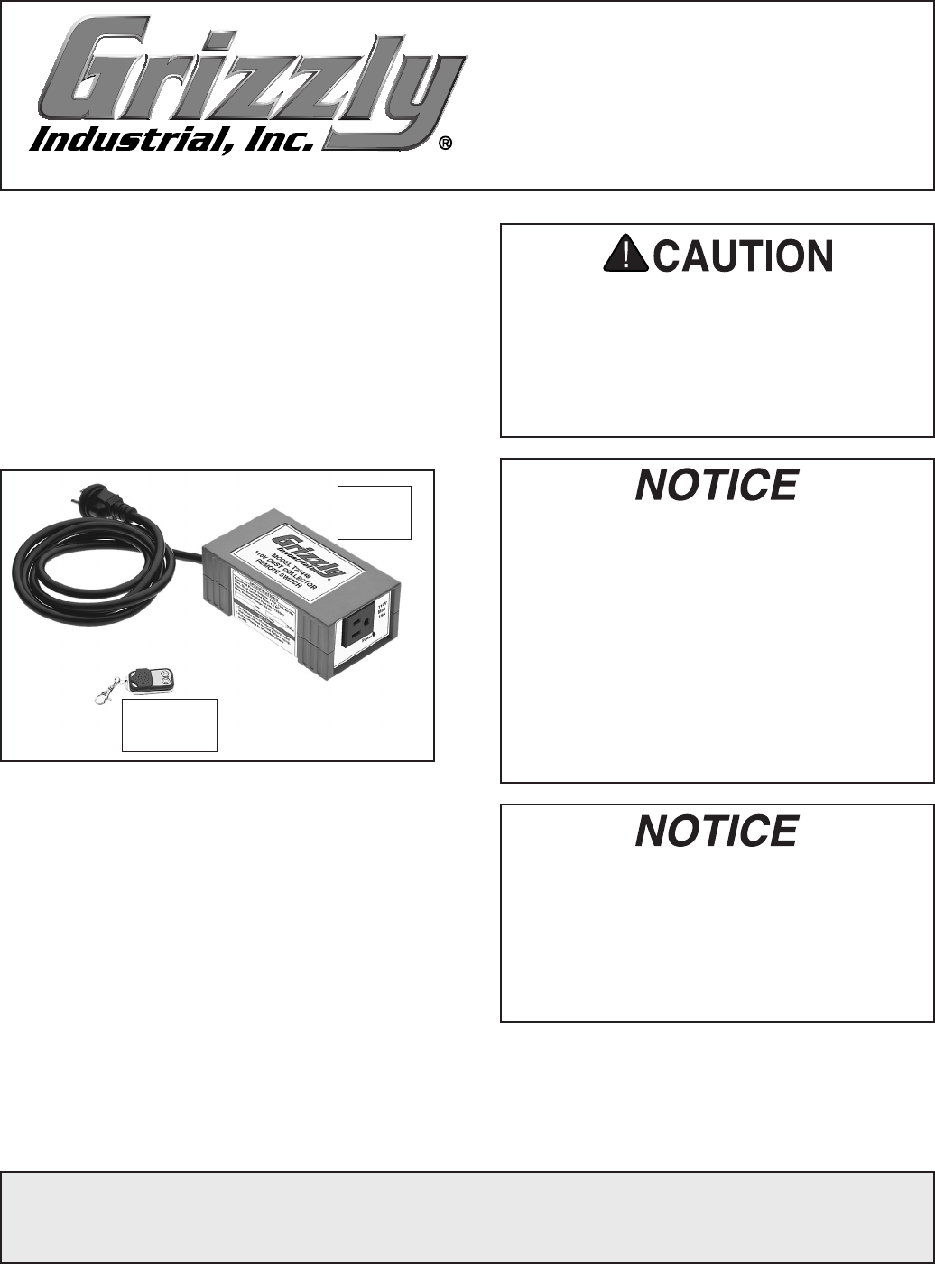
The Model T25448/T25449 Dust Collector
Remote Switch (Figure 1) allows you to remotely
turn a dust collector ON/OFF from a distance of
up to 75 feet.
Read and understand this entire document before
installation to make sure this switch box fits the
intended application.
To ensure safe operation:
• Only connect the switch box to power sup-
ply that meets the listed specifications.
• Do not connect the switch box to a dust
collector with a motor that exceeds the
listed specifications.
Specifications
Model T25448:
Power Supply ....................110V, 15A, 60 Hz
Outlet Type .................................NEMA 5-15
Max. Dust Collector HP ..................... 1.5 HP
Model T25449:
Power Supply ................... 220V, 20A, 60 Hz
Outlet Type .................................NEMA 6-20
Max. Dust Collector HP ........................ 3 HP
Remote Battery ..........................Type 23AE, 12V
Communication Type ........Radio Frequency (RF)
Max. Communication Distance ................... 75 ft.
• This remote switch is ONLY designed to
be used on dust collectors with standard
ON/OFF toggle or push-button switches—
not with magnetic switches.
• If you are unsure about the type of dust
collector switch you have, contact the dust
collector manufacturer for more informa-
tion.
• Using this switch box for applications
other than dust collectors may cause the
unit to fail and will void the warranty.
Replacement remote controllers (Model
T25507) can be purchased by contacting
Grizzly at (800) 523-4777. Before the new
remote controller can be used, the switch
box must be programmed to work with it
(refer to Programming Switch Box on Page
2 for detailed instructions).
Figure 1. Model T25448/T25449 remote switch
components.
Switch
Box
Remote
Controller
-2- Model T25448/T25449 (Mfg. Since 8/13)
Installation
1. Place the switch box in a dry, protected loca-
tion within reach of the power receptacle and
the dust collector power cord.
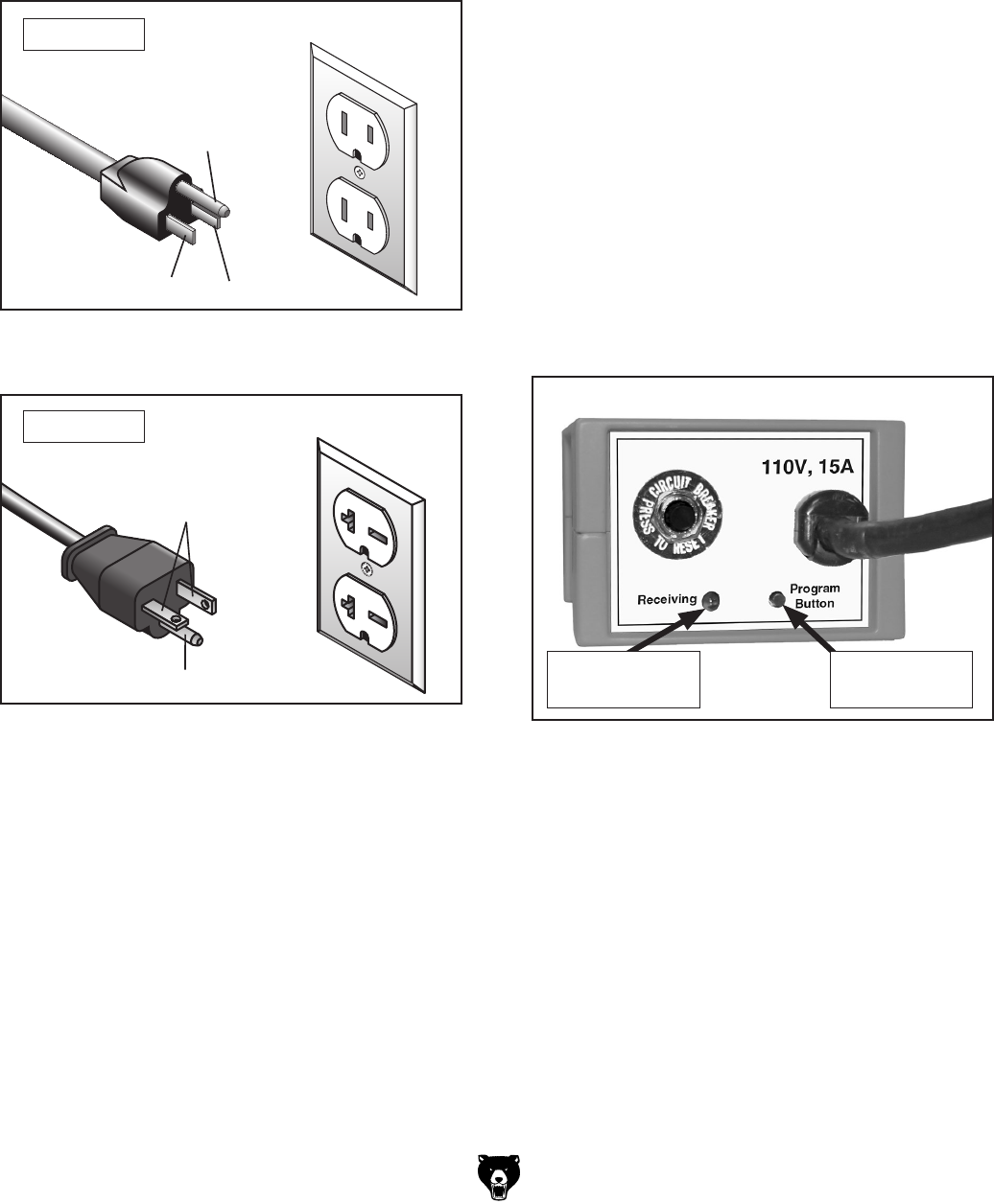
2. Plug the switch box into the proper power
receptacle (see Figures 2–3).
Grounding Prong
Neutral Hot
5-15 PLUG
GROUNDED
5-15 RECEPTACLE
Figure 2. NEMA 5-15 plug and receptacle for
Model T25448.
For T25448
3. Perform the following Programming Switch
Box procedure to make sure the remote con-
troller will operate the switch box.
4. Make sure the dust collector ON/OFF switch
is turned OFF, then plug the dust collector
into the switch box.
Grounding Prong
Current Carrying Prongs
6-20 PLUG
GROUNDED
6-20 RECEPTACLE
Figure 3. NEMA 6-20 plug and receptacle for
Model T25449.
For T25449
Programming Switch Box
You can program one switch box to operate with
several remote controllers and one remote con-
troller to operate several switch boxes. The steps
to accomplish any combination of these options
are the same.
Before beginning, read through the entire pro-
cedure to understand the required timing of the
steps.
To program the switch box:
1. Make sure the dust collector is NOT con-
nected to the switch box.
2. Make sure the red receiving light on the
switch box is illuminated (see Figure 4).
— If the red receiving light is not illuminated,
the switch box is not receiving power.
Resolve this issue before continuing.
3. Press and release the black programming
button once—you will hear three beeps and
the red receiving light will flash three times.
The switch is now in programming mode.
Note: If you do not perform the next step
within approximately five seconds after the
three beeps, you will hear one more beep
and the switch box will leave programming
mode. In this case, you will have to start
Step 3 again.
Figure 4. Programming controls on rear of
switch box.
Programming
Button
Red Receiving
Light
Model T25448/T25449 (Mfg. Since 8/13) -3-
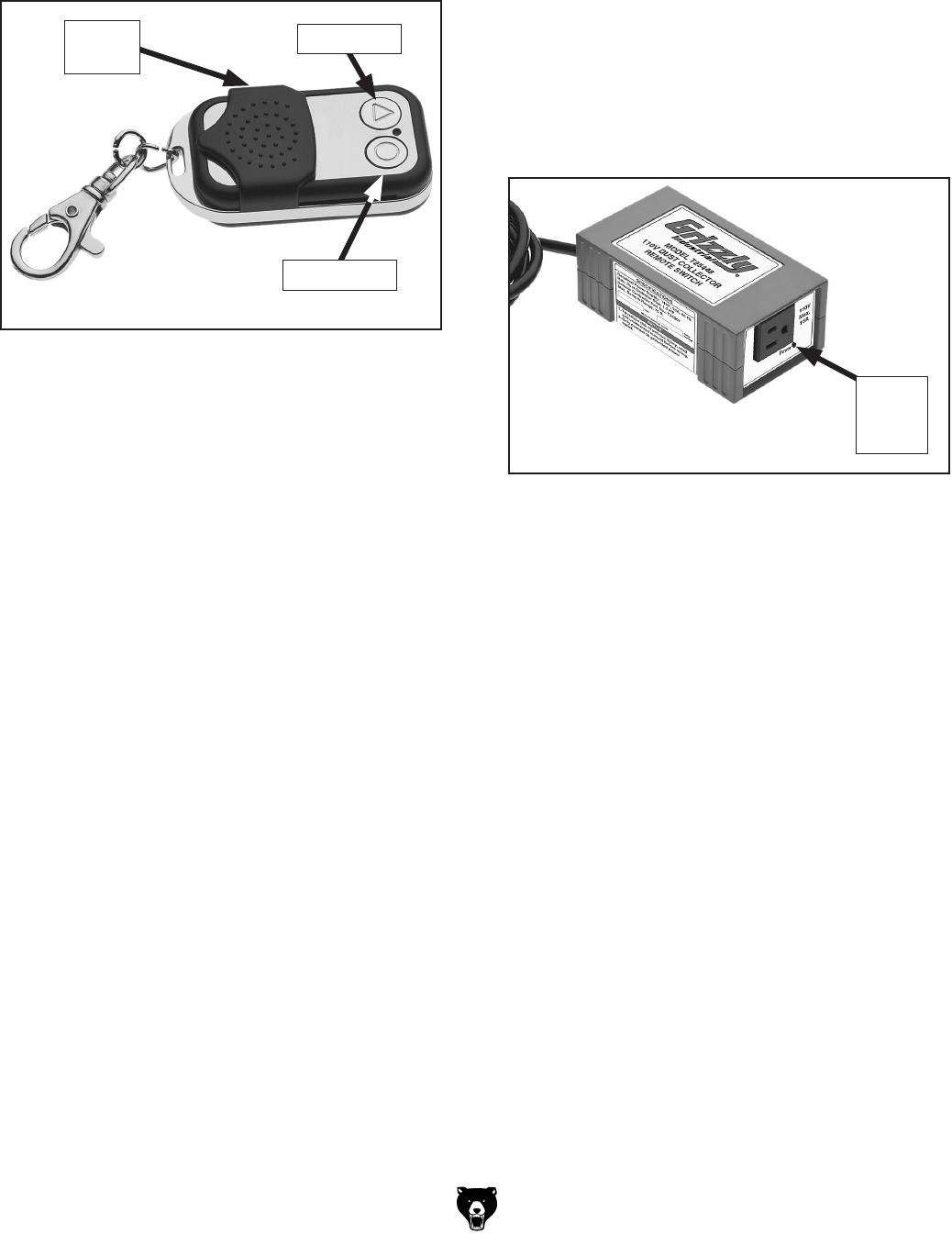
4. Press either button on the remote controller
(see Figure 5)—you will hear three beeps
and the red receiving light on the switch box
will flash three times.
Figure 5. Remote controller buttons.
ON Button
OFF Button
Sliding
Cover
5. Wait approximately five seconds and you will
hear another beep—the switch box is now
programmed to work with this remote control-
ler.
4. Press the remote controller OFF button once
to turn the dust collector OFF. The green
power light on the switch box will turn OFF.
Figure 6. Green power light on switch box.
Green
Power
Light
Operation
1. Make sure the switch box is properly installed
and correctly programmed with the remote
controller.
2. Turn the dust collector ON/OFF switch to ON.
3. Press the remote controller ON button once
to turn the dust collector ON. The green
power light on the switch box will also illumi-
nate (see Figure 6).
Un-programming Switch Box
If necessary, the switch box can be un-pro-
grammed so that it will not operated with any
remote controller. In such case, you will have
to re-program the switch box to operate with a
remote controller.
To un-program the switch box:
1. Press and hold the black programming but-
ton on the switch box for approximately five
seconds—you will hear one long beep and
the red receiving light will flash once.
2. The switch box is now un-programmed.
Notice :
The changes or modifications not expressly approved
by the party responsible for compliance could void the
user’s authority to operate the equipment.
This device complies with Part 15 of the FCC Rules.
Operation is subject to the following two conditions:
(1) this device may not cause harmful interference,
and (2) this device must accept any interference
received, including interference that may cause
undesired operation.
-4- Model T25448/T25449 (Mfg. Since 8/13)
Symptom Possible Cause Possible Solution
Switch box will not
turn ON.
1. Switch box not connected to power.
2. Remote controller not properly programmed
to operate switch.
3. Remote controller battery weak/dead.
4. Switch box circuit breaker has tripped.
5. Remote controller is out of range with
switch.
6. Wall circuit breaker has tripped.
7. Remote controller/switch at fault.
1. Connect switch box to correct power source (Page 2).
2. Properly program remote controller to operate switch
(Page 2).
3. Replace remote controller battery (this page).
4. Press the circuit breaker reset button on rear of
switch.
5. Operate the remote controller within 75 ft. of the
switch.
6. Reset wall circuit breaker. Make sure breaker is in
good condition and circuit is properly sized for dust
collector in use.
7. Test/replace.
Dust collector will
not turn ON.
1. Dust collector ON/OFF switch not turned
ON.
2. Dust collector not connected to switch box.
3. Switch box not connected to power.
4. Wall circuit breaker has tripped.
5. Dust collector at fault.
1. Turn dust collector ON/OFF switch ON.
2. Properly connect dust collector to switch box
(Page 2).
3. Connect switch box to correct power source (Page 2).
4. Reset wall circuit breaker. Make sure breaker is in
good condition and circuit is properly sized for dust
collector in use.
5. Refer to dust collector manual for troubleshooting;
contact dust collector manufacturer for technical
help.
Troubleshooting
Review the troubleshooting and procedures in this subsection if a problem develops. If you need additional
help with a procedure, call our Technical Support at (570) 546-9663.
Note: Please gather the serial number and manufacture date of your switch before calling.
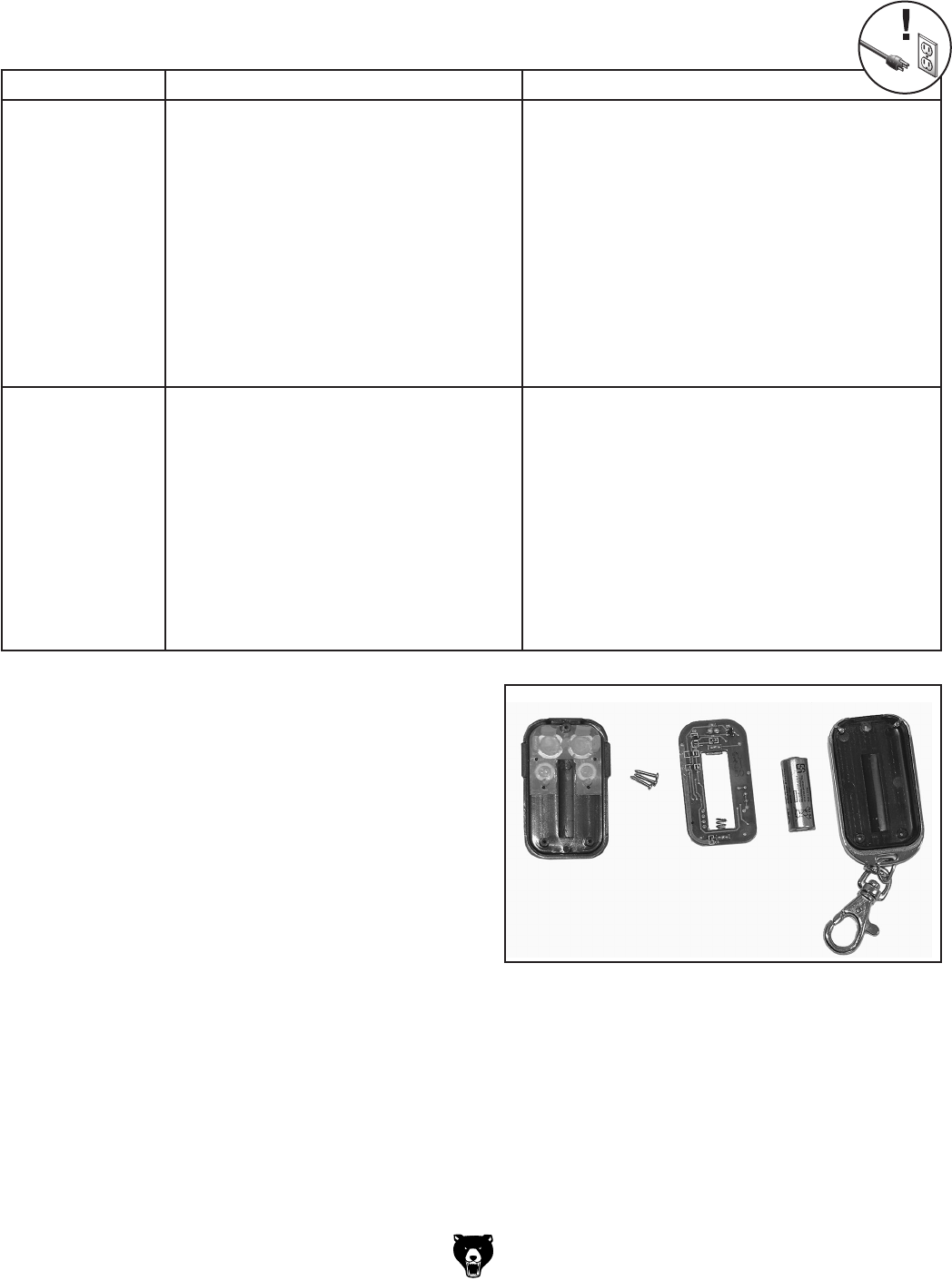
Replacing Remote Controller Battery
The remote controller is independently powered
by a Type 23AE, 12V internal battery. If the switch
box stops responding to the remote controller,
replace the battery as the first course of resolu-
tion.
To replace the remote controller battery:
1. Place the remote controller upside down on a
stable, protective surface.
2. Use a #00 Phillips screwdriver to remove the
three screws that secure the components
together.
3. Carefully separate the covers, circuit board,
and battery, as shown in Figure 8.
Figure 8. Remote controller components.
4. Replace the battery, then re-assemble the
remote controller.