Grundig Digital Radio Users Manual DRG 2007 Nd
Digital Radio to the manual 5f1a2b33-e40e-4305-bf04-779120dca3c9
2015-02-02
: Grundig Grundig-Digital-Radio-Users-Manual-430139 grundig-digital-radio-users-manual-430139 grundig pdf
Open the PDF directly: View PDF ![]() .
.
Page Count: 118 [warning: Documents this large are best viewed by clicking the View PDF Link!]
3
FOREWORD
The purpose of the Digital Radio Guide is to help engineers and managers in the radio broadcast
community understand various aspects of digital radio systems that are available in 2006. The
guide covers those systems used for transmission in different media, but not in the production
chain. The in-depth technical descriptions of the systems are available from the proponent
organisations and their websites listed in the appendices. The choice of the appropriate system
remains the responsibility of the broadcaster who should take into account the various technical,
commercial and legal factors relevant to the application.
It is my sincere hope that the publication will be a useful tool for radio broadcasters to evaluate
the various options available to them.
I would like to thank the editorial team for the excellent job they did in preparing this revised
edition of the Digital Radio Guide. The team was chaired by Wayne Heads, ABU Technical
Director, and consisted of Franc Kozamernik and David Wood, EBU, and Mike Starling, NABA.
We are grateful to the many organisations and consortia whose systems and services are
featured in the guide for providing the updates for this latest edition. In particular, our thanks go
to the following organisations:
•European Broadcasting Union
•North American Broadcasters Association
•Digital Radio Mondiale
•iBiquity Digital
•WorldDAB Forum
•WorldSpace Inc
Dr Riyadh Najm
Chairman
World Broadcasting Unions - Technical Committee
November 2006
5
TABLE OF CONTENTS
1 INTRODUCTION............................................................................................................................... 7
2 WHAT IS DIGITAL RADIO?........................................................................................................... 8
3 WHY DIGITAL RADIO? ................................................................................................................ 10
4 TERRESTRIAL TRANSMISSION SYSTEMS............................................................................. 11
4.1 DRM – DIGITAL RADIO MONDIALE ........................................................................................... 11
4.1.1 Key Features of the System Design for the Markets to be Served by the DRM System ........ 11
4.1.2 Brief Description of the DRM System ................................................................................... 12
4.1.3 Transmitter Considerations .................................................................................................. 17
4.1.4 DRM+................................................................................................................................... 18
4.2 DAB – EUREKA 147................................................................................................................... 19
4.2.1 System Development ............................................................................................................. 19
4.2.2 Principal Advantages and Challenges.................................................................................. 19
4.2.3 DAB Development Worldwide as of 2006............................................................................. 21
4.2.4 Infrastructure Requirements ................................................................................................. 25
4.2.5 Synergies with Other Systems ...............................................................................................25
4.2.6 Future Developments of DAB ............................................................................................... 27
4.2.7 Types of Receivers ................................................................................................................ 31
4.3 JAPAN'SDIGITAL RADIO BROADCASTING (ISDB-TSB) ............................................................. 35
4.3.1 Overview............................................................................................................................... 35
4.3.2 The Methods.......................................................................................................................... 35
4.3.3 Characteristics...................................................................................................................... 41
4.3.4 Receivers............................................................................................................................... 41
4.3.5 Overview of Services............................................................................................................. 42
4.3.6 Outlook for the Future .......................................................................................................... 43
4.4 IBIQUITY HD RADIO SYSTEM..................................................................................................... 44
4.4.1 HD Radio Standards Activity................................................................................................45
4.4.2 HD Radio AM and FM Receivers ......................................................................................... 45
4.4.3 HD Radio System Technical Design Overview..................................................................... 46
4.4.4 Core Services ........................................................................................................................ 47
4.4.5 HD Radio Subsystems........................................................................................................... 50
4.4.6 Receiver Systems................................................................................................................... 52
4.4.7 Features Common to North American Digital Radio Systems.............................................. 53
4.4.8 Infrastructure Requirements ................................................................................................. 56
4.5 ISSUES RELATED TO TERRESTRIAL SYSTEMS.............................................................................. 58
4.5.1 Spectrum Availability............................................................................................................ 58
4.5.2 The Implications of Simulcasting.......................................................................................... 62
4.5.3 Coverage............................................................................................................................... 63
5 SATELLITE TRANSMISSION ...................................................................................................... 65
5.1 WORLDSPACE – ITU-R SYSTEM D............................................................................................. 65
5.1.1 Receiver Systems................................................................................................................... 68
5.2 SIRIUS SATELLITE RADIO /XMSATELLITE RADIO................................................................... 69
5.2.1 Sirius Overview..................................................................................................................... 70
5.2.2 Deployment Status ................................................................................................................ 74
5.3 MOBILE BROADCASTING CORP. AND TU MEDIA CORP. – ITU-R SYSTEM E.............................. 75
5.3.1 Receiver Systems................................................................................................................... 75
6 INTERNET RADIO (IR) ................................................................................................................. 76
6.1 INTRODUCTION........................................................................................................................... 76
6.2 BRINGING RADIO TO THE INTERNET........................................................................................... 76
6
6.3 INTERNET RADIO PECULIARITIES................................................................................................ 77
6.4 INTERNET RADIO AS A COMPLEMENT TO ESTABLISHED RADIO SERVICES ................................... 78
6.5 INTERNET-ONLY STATIONS:IRPORTALS AND MUSIC PORTALS ................................................. 79
6.6 STREAMING TECHNOLOGY FOR RADIO SERVICES ........................................................................ 79
6.7 INTERNET RADIO TERMINALS AND PLAYBACK DEVICES ............................................................. 82
6.8 INTERNET RADIO'S RELATION WITH THE TRADITIONAL RADIO ................................................... 83
6.9 MEASURING AUDIENCE .............................................................................................................. 84
6.10 CASE STUDIES ............................................................................................................................ 86
6.10.1 VRT .................................................................................................................................. 86
6.10.2 Virgin Radio..................................................................................................................... 86
6.10.3 Swedish Radio multichannel audio distribution............................................................... 87
6.11 SUMMARY AND CONCLUSIONS ................................................................................................... 87
6.12 SOME IMPORTANT RADIO PORTALS ........................................................................................... 88
7 SOME SOURCES FOR THE DIGITAL RADIO GUIDE............................................................ 91
APPENDIX A THE EUREKA 147 SYSTEM - SYSTEM DESCRIPTION.................................. 94
APPENDIX B RELEVANT WORLD WIDE WEBSITES........................................................... 110
APPENDIX C GLOSSARY OF ACRONYMS.............................................................................. 112
DIGITAL RADIO GUIDE INTRODUCTION
7
1 Introduction
Digital technology has steadily transformed the way in which programmes are made and
distributed in recent years. Already many broadcasters have invested in digital systems
for contribution and production and now the switch from analogue to digital is moving
along the broadcasting chain into transmission. At the same time, digital developments
are drawing together the broadcasting, telecommunications and computer industries in a
process of convergence. For all broadcasters, this is leading to a new and challenging
business environment in which they are searching for a clear ‘multimedia’ role.
Although similar changes are happening in both radio and television, this guide deals with
radio. It is designed to help managers, including those in developing countries, identify
the technical and business forces that are driving the analogue to digital conversion
process. There are many benefits that radio broadcasters stand to gain by adopting
digital technology and the current interest in digital television should help and encourage
the switch from analogue to digital in radio broadcasting. The issue is likely to be brought
into sharper focus if and when individual countries or regional groups set timetables for
phasing out existing analogue services.
This updated Digital Radio Guide focuses primarily on the various digital radio systems in
operation today and their associated standards. The guide visits not only terrestrially
based digital system but also overviews the services now available via satellite radio.
The important development seen in this updated guide is the significant changes to
digital radio development compared to the original guide published in 1998. The first
guide presented many options for the US-based studies into digital radio as well as
satellite radio. These systems have now matured to the level that there is unlikely to be
changes in the choice for digital standards for many years. The only development
planned at present is that by the DRM Consortium with its DRM120 project.
This guide is a compilation of inputs provided by WBU members for the benefit of the
world broadcasting community. Note that references to relevant worldwide websites and
a glossary of acronyms are provided in Appendices B and C at the end of this guide.
DIGITAL RADIO GUIDE WHAT IS DIGITAL RADIO?
8
2 What is Digital Radio?
Since the early days of broadcasting, analogue systems have been used to carry
programmes from the studios to the listeners. Now, due to the growing number of
broadcasters and programme services, the frequency bands allocated to AM and FM
radio in many regions of the world are full. The resulting congestion in the radio spectrum
has led to a decline in reception quality and is a real constraint to further growth.
Furthermore, in densely populated areas, FM reception on car radios and portables can
be very poor. This is due to the effect of severe multipath propagation caused by signal
reflections and shadowing due to high buildings.
Digital transmission technology can offer much improved coverage and availability. It is
expected to replace analogue transmissions in many areas, but as digital systems are
incompatible with current AM and FM broadcasting systems, new receivers will be
needed.
In basic form, digital radio is an application of the technology in which sound is processed
and transmitted as a stream of binary digits. The principle of using digital technology for
audio transmission is not new, but early systems used for terrestrial television sound
(such as NICAM 728) need considerable bandwidth and use the RF spectrum inefficiently,
by comparison with today’s digital systems.
The development of digital radio has been helped by the rapid progress that has been
made in digital coding techniques used in RF and audio systems. This has led to
improved spectrum efficiency, more channel capacity, or a combination of these benefits.
Digital compression techniques used in audio systems have improved sound quality at
low bit rates to the extent that radio broadcasts can be made on location and then
transmitted to the broadcaster’s production studios over telephone circuits in high quality.
Ideally, to reach the widest range of listeners, a genuinely universal digital radio system
should be capable of being transmitted via terrestrial, satellite and cable systems.
There are new digital radio systems in operation. The list is set out in Table 2.1.
The table illustrates the wide spread of operational systems throughout the world.
The great strength of the present analogue transmission systems is the world-wide
standardisation on just two systems (FM and AM). This enables listeners to use one radio
to receive programmes at any location. But in the development of digital systems, it is
now clear that similar standardisation will not be so easily achieved. Differing market
requirements are driving digital systems to be more specialised and tailored to meet
regional, national, or application-oriented needs. Furthermore, the complexity of digital
systems compared to existing analogue techniques fosters this differentiation.

DIGITAL RADIO GUIDE WHAT IS DIGITAL RADIO?
9
Table 2.1. Digital Radio Systems
AVAILABILITY
SYSTEM Terrestrial in service date Satellite in
service date
Eureka 147
(ITU-R Digital System A)
1995
(for the UK, Norway,
Denmark and Sweden)
---
DRM - Digital Radio Mondiale
ETSI ES 201 980 V1.2.2 (2003-4)
International consortium
Transmissions tests
successfully since 2000;
regular broadcasting from
July 2003. For use in all
broadcasting bands below 30
MHz
---
DRM - Digital Radio Mondiale 2010
DRM+
HD Radio (iBiquity Digital)
(FCC Docket 99-325, NRSC-5
Standard) in the HF and MF Bands
Now rolling out in US ---
WorldSpace
(ITU-R Digital System D)
1998
XM Radio 2001 (North
America)
Sirius Satellite Radio 2000 (North
America)
Digital Radio Broadcasting
ISDB-TSB (Japan)
(1) ---
Notes:
--- Not applicable
(1) System under trial development. No date set for a service.
DIGITAL RADIO GUIDE WHY DIGITAL RADIO?
10
3 Why Digital Radio?
The existing AM and FM analogue systems suffer from inherent short-comings and
neither can offer uniform reception quality throughout the coverage area. AM radio
reception is constrained by bandwidth limitations, which restrict the audio quality and by
interference from other co-channel and adjacent channel transmissions. This is
particularly troublesome during the hours of darkness. The start of FM services in the
1950’s improved the audio bandwidth and overcame the night-time interference, but the
broadcasts were designed to be received using fixed receivers with external antennas.
When listened to in vehicles or on portables, reception suffered from the effects of
reflected signals (multipath) and other forms of interference, particularly in suburban and
city areas.
Another aspect of AM and FM analogue transmissions is the inefficient use of the
spectrum (relative to what is possible using digital technology). As pressure on the radio
spectrum rises, this finite resource becomes more scarce. Digital radio is seen by some
administrations as a potential source of income and spectrum, as a way to encourage the
resource to be used more efficiently.
There are many ways in which digital radio systems can improve upon analogue
systems:
•Digital signals are more robust than analogue and can be transmitted successfully at
lower transmitter powers.
•Digital systems using coded multicarrier modulation offer much improved reception
on mobile car radios and portables.
•Advanced digital compression techniques enable low bit rates to be used
successfully, whilst still producing sound of near CD quality. This makes digital
systems more spectrum efficient.
•The digital bit-stream can be used for transmitting both audio and data.
•A digital radio is much easier to use/tune than is an AM/FM radio.
•There is increasing competition for the public’s time from the non-broadcast media
such as the CD. By comparison, many AM (in particular) and FM services offer poor
audio quality.
•The data capability of digital radio can be used directly or, with some modification, for
other related broadcasting activities such as Internet radio.
DIGITAL RADIO GUIDE TERRESTRIAL TRANSMISSION SYSTEMS - DRM
11
4 Terrestrial Transmission Systems
This section provides a technical overview of the various digital radio systems available
for terrestrial application: DRM, DAB, ISDB-TSB, and HD Radio. These systems operate
in various frequency bands and offer different attributes and features.
4.1 DRM – Digital Radio Mondiale
The DRM system encompasses a high level of flexibility in its design. These are noted in
this subsection in the signal flow sequence going from the delivery from a program studio
or network control centre to a transmission site and on to reception and decoding in a
receiver.
4.1.1 Key Features of the System Design for the Markets to be Served by the
DRM System
The DRM system is a flexible digital sound broadcasting system for use in the terrestrial
broadcasting bands below 30 MHz.
It is important to recognize that the consumer radio receiver of the near future will need to
be capable of decoding any or all of several terrestrial transmissions; that is narrow-band
digital (for <30 MHz RF), wider band digital (for >30 MHz RF), and analogue for the LF,
MF, HF and VHF (including the FM) bands. In addition there is the possibility of satellite
delivery reception in the L- and S-bands. The DRM system will be an important
component within the receiver. It is unlikely that a consumer radio designed to receive
terrestrial transmissions in the near future with a digital capability would exclude the
analogue capability.
In the consumer radio receiver, the DRM system will provide the capability to receive
digital radio (sound, program related data, other data, and still pictures) in all the
broadcasting bands below 30 MHz. It can function in an independent manner, but, as
stated above, will more likely be part of a more comprehensive receiver – much like the
majority of today’s receivers that include AM and FM analogue reception capability.
The DRM system can be used in either 9 or 10 kHz channels, or multiples of these
channel bandwidths. Differences on how much of the total available bit stream for these
channels is used for audio, for error protection and correction, and for data transfer
depend on the allocated band (LF, MF or HF) and on the intended use (for example,
ground wave, short distance sky wave or long distance sky wave, with a data application
service or without one). In other words, there are modal trade-offs available so that the
system can match the needs of broadcasters worldwide.
As noted in more detail in subsequent parts of this subsection, the DRM system has the
following structure. It employs advanced audio coding (AAC), supplemented by spectral
band replication (SBR), as the main digital audio encoding. These are parts of the
MPEG-4 audio standard. SBR significantly improves perceived audio quality so that the
overall audio quality of a DRM signal is similar to that of FM (mono). Orthogonal
Frequency Division Multiplexing (OFDM) and Quadrature Amplitude Modulation (QAM)
are used for the channel coding and modulation, along with time interleaving and forward
error correction (FEC). Pilot reference symbols are injected to permit a receiver to
“equalize” the channel by comparing a known stored bit sequence with the corresponding
received sequence of these special bits, and adjusting accordingly if there are differences
in the received compared to the stored sequence.
DIGITAL RADIO GUIDE TERRESTRIAL TRANSMISSION SYSTEMS - DRM
12
The combination of these techniques results in high quality sound in a narrow channel
with robust reception in an intended coverage area with relatively low transmission power.
In addition, source coding schemes using lower bit rates than that used with AAC/SBR
are included for lesser levels of audio quality if the AAC/SBR quality level is not desired
by a broadcaster. For example, a broadcaster may want to transmit two or more “speech”
only programs. These would not require the full performance of AAC/SBR.
4.1.2 Brief Description of the DRM System
(1) Overall design
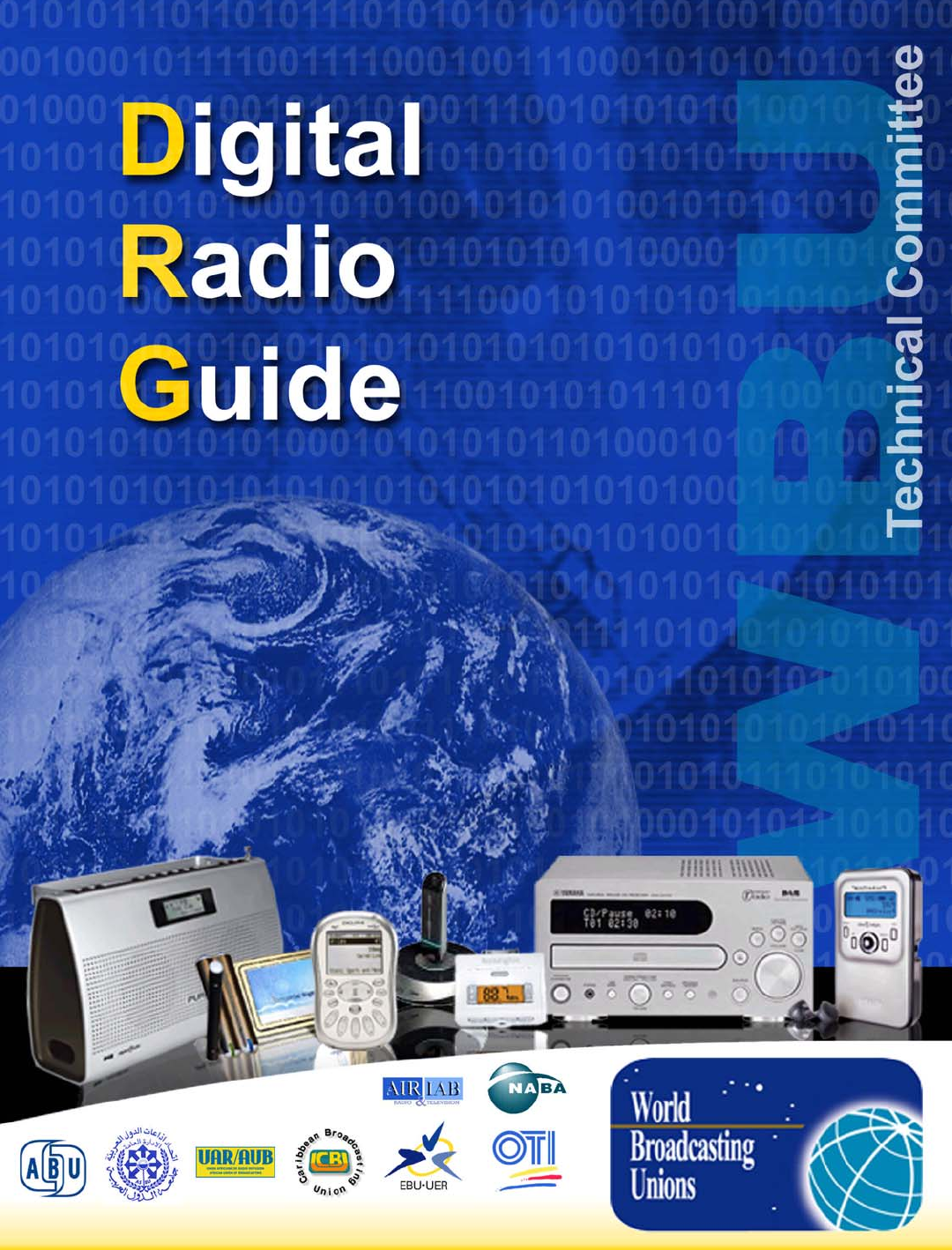
Figure 4.1: Transmission Block Diagram
source
encoder(s)
pre-coder
pre-coder
pre-coder
MUX
energy
dispersal
energy
dispersal
energy
dispersal
channel
encoder
channel
encoder
channel
encoder
OFDM signal
generator modulator
audio data
stream
SDC
information
FAC
information
data
stream
FAC
SDC
MSC
normal prot.
[high prot.]
DRM transmission signal
flow of information
normal prot.
[high prot.]
cell
interleaver
normal/[high]
protection
OFDM cell mappe
r
pilot generator
Figure 4.1 depicts the general flow of different classes of information (audio, data,
etc.) after their origination in a studio or control centre (that would be depicted to
the left of the figure) to a DRM transmitter exciter/modulator on the right. Although
a receiver diagram is not included in the figure, it would represent the inverse of
this diagram.
There are two classes of basic information:
•the encoded audio and data that are combined in the main service multiplexer;
•information that bypasses the multiplexer that are known as fast access
channel (FAC) and service description channel (SDC), whose purposes relate
to identification and control for a transmitter and for appropriate decoding
selection within a receiver.
The audio source encoder and the data pre-coders ensure the adaptation of the
input streams onto an appropriate digital format. Their output may comprise two
parts requiring two levels of protection within the subsequent channel encoder.
The multiplex combines the protection levels of all data and audio services in a
proper format within the frame structure of the bit stream.
DIGITAL RADIO GUIDE TERRESTRIAL TRANSMISSION SYSTEMS - DRM
13
The energy dispersal provides an ordering of the bits that reduces the possibility of
unwanted regularity in the transmitted signal.
The channel encoder adds redundant bits as a means for error protection and
correction and defines the mapping of the digitally encoded information into QAM
cells, which are the basic carriers of the information supplied to the transmitter for
modulation.
Cell interleaving rearranges the time sequence of the bits as a means of
“scrambling” the signal so that the final reconstruction of the signal at a receiver will
be less affected by fast fading than would be the case if “continuous” speech or
music were transmitted.
The pilot generator injects information that permits a receiver to derive channel-
equalization information, thereby allowing for coherent (includes phase information)
demodulation of the signal.
The OFDM cell mapper collects the different classes of cells and places them on a
time-frequency grid.
OFDM depends on each of many subcarriers carrying its own sinusoidal
amplitude/phase signal for a short period of time. The ensemble of the information
on these subcarriers contains what is needed for transmission. In the case of DRM,
for a 10 kHz channel, there are hundreds of subcarriers.
The modulator converts the digital representation of the OFDM signal into the
analogue signal that will be transmitted via a transmitter/antenna over the air –
essentially phase/amplitude representations as noted above modulating the RF.
With a non-linear high-powered transmitter, the signal is first split into its amplitude
and phase components for injection in the anode and grid circuits, respectively,
and then recombined (by the action of the transmitter itself set at the correct
differential delay time), and then recombined prior to final emission. This splitting is
not necessary for linear amplification.
(2) Distribution Interface
Referring to the extreme left of Figure 4.1, apart from audio and data applications
that are multiplexed, additional information is sent that is required to instruct the
transmitter to select the correct mode, error protection level, etc. and to send
information in the transmission to the receivers to permit them to switch to the
selection of several variables to allow for proper decoding. (The boxes and arrows
for this are not shown directly in Figure 4.1.) In the aggregate, this collection of
information and the means to get it to the transmitting station is called the
“Distribution Interface” (DI).
These signals can emanate from a studio, or from a more elaborate network
control centre, and be transmitted via land lines or via satellite circuits to the
appropriate transmitter station(s). These details will not be noted here, but can be
found in ETSI documents TS 102 821 and TS 102 820, both dated July 2003.
In terms of connections with other parts of the DRM system, these signals, as
appropriate, are placed in either the Fast Access Channel (FAC) or the Service
Description Channel (SDC) for transmission to receivers.
There are 4 categories of data associated with the Distribution Interface:
DIGITAL RADIO GUIDE TERRESTRIAL TRANSMISSION SYSTEMS - DRM
14
•MDI – Multiplex Distribution Interface: covers the transport of data and
commands from the DRM multiplexer to the DRM Modulator.
•MCI – Modulator Control Interface: covers the remote signalling of commands
and setups to the modulator and transmitter equipment.
•SDI – Service Distribution Interface: covers the transport of data and
commands from the studio and other sources to the DRM Multiplexer.
•RSCI – Receiver Status and Control Interface: covers the transport of receiver
status information in addition to the DRM multiplex as well as commands to
control the receiver’s behaviour.
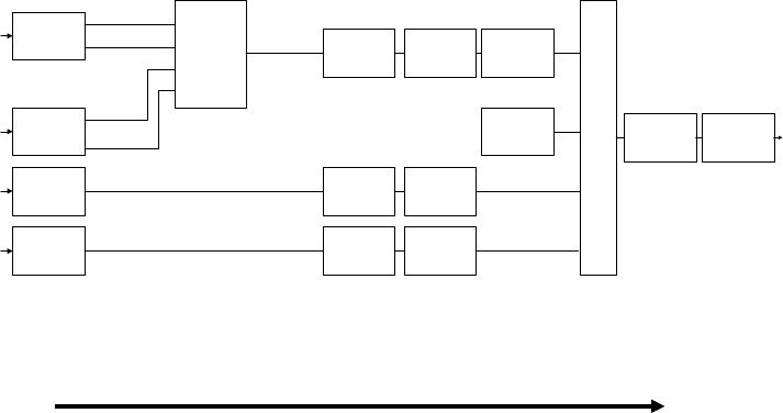
(3) Audio Source Coding
Figure 4.2 depicts the variety of digital audio encoders in the DRM system – in
effect, AAC, AAC with SBR, CELP and HVXC – all of which can operate in a range
of bit rates, and consequently produce a range of audio quality. (See the ETSI
DRM standardization document ES 201 980 v2.1.1, 2004-06.)
The full range runs approximately from 2 kbps (HVXC minimum) to 25 kbps (AAC
maximum) within the 9/10 kHz channels for standard broadcasting in the
broadcasting bands below 30 MHz. HVXC and CELP are used for “speech only”
applications. AAC and AAC/SBR, within the permissible range, result in excellent
music and speech audio quality.
Figure 4.2: DRM Source Encoding and Decoding
SBR Encoder
(configuration
dependent)
AAC
Encoder
CELP
Encoder Audio
super
framing
Audio-
signal
mux &
channel
coding
HVXC
Encoder
DRM Source Encoding
DIGITAL RADIO GUIDE TERRESTRIAL TRANSMISSION SYSTEMS - DRM
15
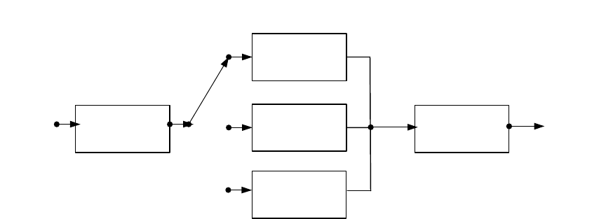
DRM Source Decoding
super
framing
demux
AAC
Decoder
CELP
Decoder SBR
Decoder
bit
stream
Audio
output
HVXC
Decoder
Extensive tests on these codecs at the sampling rates and resulting “bandwidths”
have determined that AAC and especially AAC with SBR produce a perceived
audio quality to listeners that is effectively the equivalent of monophonic FM in a 9
or 10 kHz channel. HVXC produces intelligible speech quality with bit rates of 2 to
4 kbps for HVXC and CELP produces excellent speech quality using around 8 kbps.
All of these codecs are a part of the MPEG-4 audio standard.
SBR (Spectral Band Replication) is a special means of enhancing the perception of
a spectrally truncated low band audio signal by utilizing, on a dynamic basis, the
spectral content of the low band information to simulate the missing higher band
behaviour. This requires about 2 kbps and therefore does not seriously subtract
from a 20 to 25 kbps AAC output.
In concept, the technique is not complicated. Consider a violin as an example. A
string stimulated by a bow and the placement of a finger on the string produces a
fundamental frequency and harmonics characteristic of a violin. These frequencies
can go as high as the audibility of the human ear – say somewhere between 15
and 20 kHz.
For a 9 or 10 kHz channel, the AAC sampling and processing of the violin’s output
can only cover the lower part of the audio spectrum, for example not higher than 6
kHz. The SBR algorithm examines this lower band spectrum on a dynamic basis
and infers what the “missing” higher audio frequency “harmonics” probably are.
The level of re-inserted harmonics depends on the 2 kbps SBR helper signal which
describes the shape of the spectral energy in the original signal before truncation
for AAC coding stereo (which uses an additional 2 kbps of SBR). From the
standpoint of a listener, the combined audio output sounds like 15 kHz audio rather
than 6 kHz audio.
(4) Multiplexing, including special channels and energy dispersal
This section refers to the left side of Figure 4.1 through “energy dispersal”, not
including the DI and audio/data encoding portions.
As noted in Figure 4.1, the DRM system total multiplex consists of 3 channels: the
MSC, the FAC and the SDC. The MSC contains the services – audio and data. The
DIGITAL RADIO GUIDE TERRESTRIAL TRANSMISSION SYSTEMS - DRM
16
FAC provides information on the signal bandwidth and other such parameters, and
is also used to allow service selection information for fast scanning. The SDC gives
information to a receiver on how to decode the MSC, how to find alternative
sources of the same data, and gives attributes to the services within the multiplex.
The MSC multiplex may contain up to 4 services, any one of which can be audio or
data. The gross bit rate of the MSC is dependent on the channel bandwidth and
transmission mode being used. In all cases, it is divided into 400 millisecond
frames.
The FAC’s structure is also built within a 400 millisecond frame, and is designed
without interleaving, for example, to ensure rapid delivery of the information it
contains. The design without interleaving is also to ensure fastest decoding of
basic data by the Rx before it can do the audio decoding. The channel parameters
are included in every FAC frame segment. The service parameters are carried in
successive frames, one service per frame. The names of the FAC channel
parameters are: base/enhancement flag, identity, spectrum occupancy, interleaver
depth flag, modulation mode, number of services, reconfiguration index, and
reserved for future use. These use a total of 20 bits. The service parameters within
the FAC are: service identifier, short identifier, conditional access, language,
audio/data flag, and reserved for future use. These use a total of 44 bits.
The SDC’s frame periodicity is 1200 milliseconds. The fields of information are:
multiplex description, label, conditional access, frequency information, frequency
schedule information, application information, announcement support and
switching, coverage region identification, time and date information, audio
information, FAC copy information, and linkage data. As well as conveying these
data, the fact that the SDC is inserted periodically into the waveform is exploited to
enable seamless switching between alternative frequencies.
(5) Channel coding and modulation
The coding/modulation scheme used is a variety of coded orthogonal frequency
division multiplexing (COFDM), which combines the OFDM with the Multi-Level
Coding (MLC) based upon convolutional coding. The convolutional coding provides
a level of error protection. These two main components are supplemented by time
interleaving (“scrambling” of the bit stream) and the provision of pilot
(predetermined value) cells for instantaneous channel estimation. All of this
mitigates the effects of short-term signal fading, whether selective or flat.
Taken together, this combination provides excellent transmission and signal
protection possibilities in the narrow 9 or 10 kHz channels in the LF, MF and HF
broadcasting frequency bands. It can also be used for “multi-channel” DRM use;
that is 18 or 20 kHz channels, using 2 contiguous ITU-R channels. This level of
bandwidth will permit good stereo broadcasting.
For OFDM, the transmitted signal is composed of a succession of symbols, each
including a “guard interval,” which is a cyclic time prefix that provides a “dead time”
to counter intersymbol interference due to multipath delay spread. Orthogonality
refers to the fact that, in the case of the design of the DRM system, each symbol
contains around between 100 and 200 subcarriers spaced evenly across the 9 or
10 kHz channel in such a way that their signals do not interfere with each other
(are orthogonal). The precise number of subcarriers, and other parameter
considerations, are a function of the actual letter modes used: ground wave, sky
wave, and highly robust transmissions.
DIGITAL RADIO GUIDE TERRESTRIAL TRANSMISSION SYSTEMS - DRM
17
QAM is used for the modulation that is impressed upon the subcarriers to convey
the information. Two primary QAM constellations are used: 64-QAM and 16-QAM.
The former provides the highest audio quality, but is less robust than the latter. In
addition, a 4-QAM (QPSK) signal, which is very robust, is used for some of the
signalling (but not for the MSC).
The interleaver time span (applied to the MSC) for HF transmission is around 2.4
seconds to cope with time and frequency selective fading by protecting the audio
and data from rapid fades during the natural sequence of speech and music.
Owing to the less difficult propagation conditions for the LF and MF bands, a
shorter interleaver of around 0.8 seconds can be used.
The multi-level convolutional coding scheme uses code rates in the range between
0.5 and 0.8, with the lower rate being associated with the difficult HF propagation
conditions. A 0.5 code rate means that only half the transmitted bits within the
overall coded block are used for the actual services in the multiplex, whereas a 0.8
rate means 80% are.
4.1.3 Transmitter Considerations
Beyond the modulator box in Figure 4.1 is the transmitter exciter. The DRM system
exciter can be used to impress signals on either linear or non-linear transmitters. It is
expected that high-powered non-linear transmitters will be the more usual way of
transmitting, much as is done now with analogue modulation. However, there are
broadcasting service situations where very low powered linear transmissions could be the
best way to serve the public.
With respect to non-linear amplification (Class C operation), the incoming DRM signal
needs to be split into its amplitude and phase components prior to final amplification.
Using QAM modulation, there is a small discrete set of possible amplitudes and phases.
The amplitude component is passed via the anode circuitry; the phase component is
passed through the grid circuitry. These are then combined with the appropriate time
synchronization to form the output of the transmitter.
Measurements of the output spectra show the following: the energy of the digital signal is
more or less evenly spread across the 9 or 10 kHz channel, the shoulders are steep at
the channel edges, and drop rapidly to 40 dB or so below the spectral density level within
the assigned channel, and the power spectral density levels continue to decrease beyond
the 4.5 or 5 kHz from the central frequency of the assigned channel with a rapidity that
permits conformance to the ITU-R mask for the use of the channels.
(1) Over the air
The digital phase/amplitude information on the RF signal is corrupted to different
degrees as the RF signal propagates. Some of the HF channels provide
challenging situations of fairly rapid flat fading, multipath interference that produces
frequency-selective fading within a channel and large path delay spreads of a few
milliseconds or more, and ionospherically induced high levels of Doppler spreads
on the order of 1 or more hertz.
The error protection and error correction incorporated in the DRM system design
mitigates these effects to a great degree. This permits the receiver to accurately
decode the transmitted signal information.
DIGITAL RADIO GUIDE TERRESTRIAL TRANSMISSION SYSTEMS - DRM
18
Extensive field tests have verified these performance statements.
(2) Selecting, demodulating and decoding of a DRM system signal at a receiver
A receiver must be able to detect which particular DRM system mode is being
transmitted to handle it properly. This is done by way of the use of many of the
field entries within the FAC and SDC.
Once the appropriate mode is identified (and is repeatedly verified), the
demodulation process is the inverse of that shown in Figure 4.1. Similarly, the
receiver is also informed which services are present, and, for example, how source
decoding of an audio service should be performed.
For much more detail on DRM system, refer to the following references
•ETSI ES 201 980 v 2.1.1 (2004-06): the “signal in the air” specification
•ETSI TS 101 968 v0.0.2 (2002-08): the data applications specification
•ETSI TS 102 820 and TS 102 821: the distribution interface specifications
4.1.4 DRM+
While DRM currently covers the broadcasting bands below 30 MHz, the DRM consortium
voted in March 2005 to begin the process of extending the system to the broadcasting
bands up to 120 MHz. DRM Plus will be the name of this technology and wider bandwidth
channels will be used, which will allow radio stations to use higher bit rate, thus providing
higher audio quality. One of the new channel bandwidths that is likely to be specified is
50 kHz, which will allow DRM+ to carry radio stations at near CD-quality. The design,
development and testing phases of DRM’s extension, which are being conducted by the
DRM consortium are expected to be completed by 2007-2009. A 100 kHz DRM+
channel has sufficient capacity to carry one mobile TV channel: it would be feasible to
distribute mobile TV too over DRM+ than via either DAB or DVB-H.

DIGITAL RADIO GUIDE TERRESTRIAL TRANSMISSION SYSTEMS - DAB
19
4.2 DAB – Eureka 147
Eureka 1471 is a digital radio system developed in Europe for reception by mobile,
portable and fixed receivers with a simple non directional antenna. It can be used in
terrestrial, satellite, hybrid (satellite with complementary terrestrial), and cable broadcast
networks and has been designed to operate at any frequency from 30 to 3000 MHz. In
practice, Eureka 147 is being implemented in two spectrum bands, VHF Band III and L
Band. Further details of Eureka 147 can be found in Appendix A: The Eureka 147
System Description.
4.2.1 System Development
Eureka2 was established in 1985 by 17 countries and the European Union to encourage
a bottom up approach to technological development and to strengthen the competitive
position of European companies on the world market. It supports the competitiveness of
European companies through international collaboration, in creating links and networks of
innovation. The 147th Eureka technical project was to develop a digital radio system,
hence Eureka 147.
The Eureka 147 Consortium3 was founded in 1987 with 16 partners from Germany,
France, The Netherlands and the UK. The Eureka 147 standard was defined in 1993 with
ITU Recommendations released in 1994 and an initial ETSI standard released in 1995.
Eureka closed the Eureka 147 project on 1 January 2000.
The first Eureka 147 prototype equipment was demonstrated in 1988 on the occasion of
the Second Session of WARC-ORB conference held in Geneva. The first consumer type
Eureka 147 receivers developed for pilot projects were released in 1995. The first Eureka
147 services commenced transmitting in the UK, Denmark and Sweden in 1995. Eureka
147 was officially launched at the Berlin IFA (a major consumer electronics show) in 1997.
The WorldDAB Forum4 was formed in 1995 to encourage international cooperation and
coordination for the introduction of Eureka 147 onto the consumer market. The technical
work previously carried out by Eureka 147 now takes place within the Technical and
Commercial Committee of the WorldDAB Forum. In August 2003, DRM and WorldDAB
announced they would collaborate in the development of their systems.
4.2.2 Principal Advantages and Challenges
Advantages
Eureka 147 is a mature technology that has been implemented in the UK, Germany and
Canada and extensively tested in other parts of Europe and in other countries including
Australia.
Eureka 147 is defined by international ITU recommendations, European ETSI, Cenelec
and IEC standards and national standards (e.g., British receiver standards).
1Eureka 147 is also known as DAB, Eureka DAB, S!147 (S! is the logo for Eureka projects) and ITU System A. T-DAB
and S-DAB may also be used to distinguish between terrestrial and satellite versions of Eureka 147.
2Further information on Eureka at www.eureka.be
3Further information on Eureka-147 consortium at
http://www.eureka.be/ifs/files/ifs/jsp-bin/eureka/ifs/jsps/projectForm.jsp?enumber=147.
4Further information on WorldDAB forum at http://www.worlddab.org/dab
DIGITAL RADIO GUIDE TERRESTRIAL TRANSMISSION SYSTEMS - DAB
20
Many ancillary aspects of the Eureka 147 system, such as multimedia delivery,
distribution interfaces and user interactivity are also formally defined in ETSI standards.
Eureka 147 can be implemented for a range of applications such as wide area or local
delivery of audio and data services for mobile, portable and fixed reception. It can be
delivered terrestrially, via satellite, cable or a mixture of terrestrial and satellite.
Eureka 147 is designed to be used across a wide spectrum range, from 30 to 3000 MHz,
but has only been implemented using VHF Band III and the 1452 to 1492 MHz segment
of the L Band.
Eureka 147 uses a wideband COFDM modulation system which provides a robust
transmission which is multi path resilient and can provide high availability coverage.
Eureka 147 can be implemented using on channel repeaters in SFNs or low power gap
fillers and extenders. SFNs may also provide “network gain” giving improved service
availability over single channel services.
Eureka 147 can accommodate a varying number of audio services of differing quality with
associated data. The audio quality can range from simple mono speech to CD quality. An
increase in quality requires higher data rates for each audio service, hence reducing the
number of services that can be delivered. Data can also be delivered independently of
the audio services.
Eureka 147 uses mature technologies such as MPEG 1 Layer II and MPEG 2 Layer II
audio coding systems and COFDM modulation, which are also used in the DVB T video
broadcasting standard. This should lead to cheap single chip solutions for receivers.
Eureka 147 has been extensively standardised by European standards organisations and
it would be fairly straightforward for these standards to be adopted as Australia standards
by Standards Australia.
A growing number of Eureka 147 receivers are now available for portable, PCs, mobiles,
in car and in house reception.
Challenges
The MPEG 1 Layer II and MPEG 2 Layer II audio coding systems are now somewhat
dated (compared with new systems) but they offer excellent robustness against channel
errors due to unequal error protection (UEP). The system allows for inclusion of newer
coding systems as independent data, but DAB receivers would need to be adapted or
replaced to receive these services.
While a wide range of DAB receivers is already available on the market, they are still
generally seen as being too costly for general public acceptance, particularly when
compared to the very cheap AM and FM radios that many listeners currently use.
However, as Eureka 147 services have expanded, the cost of receivers have
considerably dropped in price.
Eureka 147 requires services to be multiplexed together before transmission. All audio
programs and data services in a given Eureka 147 channel will therefore have similar
coverage and reception quality.
The standard capacity of Eureka 147 multiplexes means that conversion would require
existing services to be grouped into blocks of 6 or more services per multiplex, all of
which would then cover the same area. In a conversion model, this would pose
DIGITAL RADIO GUIDE TERRESTRIAL TRANSMISSION SYSTEMS - DAB
21
challenges for many current radio broadcasting markets, which are typically served by a
mixture of narrowcasting, community, commercial and national services using AM and
FM frequencies with different or overlapping licence and coverage areas giving local,
medium or wide area coverage. Conversely, the requirement for multiplexing could over
time reduce the number of transmission sites and result in more consistent coverage of
services.
Eureka 147 uses spectrum that is often used for analogue and digital television services
(VHF Band III), and radio communication services (L Band). If a conversion model is
used for the introduction of digital radio finding, sufficient spectrum for the conversion of
all analogue radio broadcasting services to digital will not be easy, particularly as L Band
will require more transmitters to provide wide area coverage and adequate reception in
urban areas.
4.2.3 DAB Development Worldwide as of 2006
More than 40 countries have legislated for the integration of DAB Digital Radio in Europe
and Worldwide. Outside Europe the key areas of development are found in Canada, the
Asia-Pacific Region and South Africa.
(1) Belgium
DAB Digital Radio launched in Belgium in September 1997 with a multiplex
operated by the Flemish public broadcaster VRT. Today, the VRT multiplex covers
the Flemish Community and has nine audio stations. Four of these channels are
unique to DAB Digital Radio. RTBF, the public broadcaster for the French
community, has a multiplex covering the French community with five audio stations,
all simulcasts of existing analogue stations.
(2) Canada
DAB launched in Canada in November 1999. Stations in Toronto, Montreal and
Vancouver started operating in 1999; Ontario in 2000; and Ottawa in 2003. There
are currently a total of 73 licensed Digital Audio Broadcast DAB stations in Canada:
15 stations in Ottawa, 25 in Toronto, 15 in Vancouver, 12 in Montreal and 6 in
Windsor. The stations operating in these five cities provide services to some 11
million potential listeners or more than 35% of the population. Seven DAB stations
(4 commercial and 3 public) are field testing in Halifax, Nova Scotia.
DAB has yet to be embraced by consumers in Canada. The industry is currently
evaluating next steps with respect to digital radio rollout. Implementation of other
digital radio systems is under consideration, particularly as rollout of HD Radio in
the neighbouring United States proceeds.
(3) Denmark
Danish Broadcasting Corporation (DR) is currently broadcasting 18 DAB
“channels.” On September 1, 2005, the commercial broadcasters Sky Radio and
Radio 100 FM (owned by Talpa Radio International) commenced transmission on
DIGITAL RADIO GUIDE TERRESTRIAL TRANSMISSION SYSTEMS - DAB
22
the DAB networks. Both started simulcasting their FM stations utilising 25 percent
respectively on the national and the two regional networks. DR continues
broadcasting in the remaining 75 percent of both networks.
(4) France
Public broadcaster, Radio France, serves an area covering Paris, Marseille,
Toulouse and Nantes, broadcasting six stations in each of its service areas.
(5) Germany
Germany is among the leading European proponents of DAB Digital Radio with a
large local and regional network. Current figures put coverage in Germany at 78
per cent of the population, rising to 85 per cent by the end of 2005. Germany is the
primary DAB digital radio country in mainland Europe boasting some 120 radio
stations, both public and commercial, on a variety of state-wide as well as local
digital multiplexes. As far as data services are concerned, Germany is at the fore.
The focus lies on news and traffic information, using text and pictures. In March
2005, BLM, the Bavarian Media Authority, launched a pilot project called Digital
Advanced Broadcasting that will aim to use DAB to broadcast radio and video
content, as well as data services, to new portable receives. The pilot will take
place in Regensburg and is expected to last for two years with the aim to work
towards comprehensive coverage of FIFA World Cup 2006 via mobile
entertainment devices.
(6) Italy
Current population coverage in Italy stands at approximately 45% for commercial
operators and 20% for national public operators. There is a scarcity of Band III
spectrum and its use and management for digital and /or analogue TV is yet to be
fully solved. This has caused delay in the roll-out of DAB in Italy.
Italy has been broadcasting DAB Digital Radio since 1995 when public broadcaster
RAI began simulcasting its existing services. In 1998, eight commercial analogue
operators formed a consortium called Club DAB Italia in order to simulcast their
own stations on their own digital multiplex.
Currently nine national commercial stations are broadcast by the Club DAB Italia
consortium in the Milan area and vast adjacent areas and in Rome and adjacent
areas, for about 30 percent of population coverage. Also, five national public
services are simulcast on a multiplex reaching less than 20 per cent population
coverage.
(7) Singapore
Regular DAB Digital Radio services in Singapore were launched on 19th
November 1999. The MediaCorp Radio Singapore Pte Ltd dubbed their multiplex
SmartRadio. SmartRadio carries 14 radio services - six of which are available
exclusively on DAB radio and eight are simulcasts of the more popular FM stations.
In April 2005, Rediffusion, which is Singapore’s sole subscription radio broadcaster,
DIGITAL RADIO GUIDE TERRESTRIAL TRANSMISSION SYSTEMS - DAB
23
was awarded a license to provide the world’s first DAB subscription services and
operate its own multiplex.
(8) South Korea
In 2002, the Ministry of Information and Communication (MIC) in Korea approved
the use of DAB for the transmission of audio, video and data using Digital
Multimedia Broadcasting (DMB). In March 2005, six service providers were
selected by the Korean Broadcasting Commission (KBC) to receive licences: KBS,
MBC, SBS, YTN DMB, K-DMB and KMMB. The six broadcasters will in total carry
6 video, 18 audio and 12-18 data programmes, and all will be free of charge at first
to make the service universally available.
(9) Spain
Spain enjoys a strong commitment to DAB Digital Radio, with the current 52 per
cent population coverage expected to rise to 80 per cent by 2006.
DAB Digital Radio in Spain began with pilot stations in 1998 and today is a mix of
public and commercial broadcasting, with 18 stations transmitting digitally.
Spanish broadcasters are currently experimenting with data services and there are
plans for local DAB Digital Radio stations.
(10) Sweden
Whilst there is no coverage requirement built into the digital radio legislation in
Sweden, Swedish Radio, the public broadcaster, covers 85 per cent of the
population. Since 2002, a temporary reduction of the transmissions to 37 per cent
population coverage has been made for financial reasons.
(11) Switzerland
Switzerland currently has approximately 4 million potential listeners (60% of Swiss
population). In 2006, the coverage area in the German speaking part of
Switzerland will be enlarged and indoor reception enhanced. Also, full DAB
coverage across Switzerland has been approved for 2007-2008.
(12) Taiwan
In June 2005 the Taiwan Government awarded 6 commercial multiplex licenses: 3
nation-wide SFN licenses and 3 regional licenses (covering the major conurbations
like Taipei and Causing).
DIGITAL RADIO GUIDE TERRESTRIAL TRANSMISSION SYSTEMS - DAB
24
(13) United Kingdom
The public service broadcaster, the BBC, has been promoting its DAB Digital Radio
stations since September 1995 and at present covers over 85 per cent of the
population and includes the major motorway network. Digital One, the UK’s only
national commercial operator, runs the world's biggest digital radio network, with
more than 90 transmitters. Further transmitters are planned to expand the network
towards 90 per cent coverage.
Mid- 2005 saw nearly 150 DAB digital radio products in the market with today’s
figures far in excess of this. The range of DAB radios includes portables, hand-
helds, boom boxes, clock radios, micro systems, home cinema and in-car products.
Established manufacturers have helped to drive sales with high profile
advertisements in the national press.
The BBC has run a number of campaigns on television, radio and online promoting
DAB digital radio and programme content. Each campaign has seen a surge in
sales of products and consumer awareness rising. During 2005, the BBC
continued to promote individual services and content.
The Digital Radio Development Bureau (DRDB) is funded and supported by UK
broadcasters including the BBC, Digital One, EMAP Digital Radio, MXR and GCap
media. The DRDB's task is to ensure DAB's wide accessibility and swift adoption
in the UK.

DIGITAL RADIO GUIDE TERRESTRIAL TRANSMISSION SYSTEMS - DAB
25
Table 4.1. Eureka 147 Main System Features
EUREKA 147
Main System Features
Single Frequency Network (SFN)
capability
All transmitters working on a single
frequency.
Flexible audio bit rate Allows reconfiguration of the multiplex.
Data services Separately defined streams or packets.
Programme Associated Data (PAD) Embedded in the audio bit stream and
adjustable.
Facilitates Conditional Access DAB ensemble transports conditional
access information (CAI) and provides
signal scrambling mechanism.
Service Information Used in the operation and control of
receivers.
Operating frequency range 30 MHz to 3 GHz.
4.2.4 Infrastructure Requirements
Eureka 147 is a wideband technology requiring services to be multiplexed before
transmission. The use of VHF and UHF bands means Eureka 147 services will be
typically transmitted from high sites such as the tops of hills, buildings or towers.
In general, new Eureka 147 services are also likely to be co-located with existing FM
radio or television transmission services given the cost of developing new sites and the
increasing difficulty in getting local council planning approval for new transmission sites.
In Canada, implementation of the Eureka system uses a new band (L-Band), hence new
transmitters, antenna system, exciter and encoders have been required. Stations that
were originally broadcasting more than one FM program from the same site can fully
encapsulate the multiplexed stream of the DAB system in the STL (studio-to-transmitter
link), significantly reducing the costs associated with discrete feeder links. Canada’s
DAB allotment plan has room for the replacement of all existing AM and FM stations in
the L-Band. The plan also includes many empty allotments for future services. Finally,
since the plan was based on providing only five programming channels in each DAB
multiplex, new audio coding schemes will allow for the possible implementation of two to
three additional services in each ensemble.
4.2.5 Synergies with Other Systems
(1) DAB and GSM (Global System for Mobile Communications)
DAB is an efficient broadcasting (e.g., one-to-many) system capable of providing
reliably digital services to all users located in a coverage zone in real time. It is
especially suitable for the reception to mobile and portable receivers and in the
areas in which the direct line of sight between the transmitter and the receiver is
not possible.
On the other hand, GSM (Global System for Mobile Communications) and its
successors (GPRS and UMTS) are more suitable to deliver on-demand media
DIGITAL RADIO GUIDE TERRESTRIAL TRANSMISSION SYSTEMS - DAB
26
services to individual clients or relatively small groups of clients. The telecom
systems are technically able to provide services to several users in the same time,
providing that the number of simultaneous users (or, in other words, the total
bandwidth capacity) does not exceed a certain level, or else the network collapses
rapidly. Also, the use of telecom services in the "one-to-many" scenario is much
more expensive for the user than the use of DAB (or DVB) broadcast systems.
It may be advantageous for both broadcasters and telecoms to provide a
combination of both one-to-many and one-to-one applications concurrently. For
example, a traffic/travel information service may consist of two parts: a basic part
and a value-added part. The former would be carried over the broadcast network to
everybody (possibly for free), whereas the latter would be available on-demand
over the telecom network and would be paid-up according to a tariff agreed.
As an example of such synergy, Nagra-Futuris has created an IT infrastructure for
hosting end-to-end interactive services based on the existing GSM and DAB
technologies. The system provides back-channel communication, conditional
access, data warehousing, integrated billing/clearing and interfacing to external M-
commerce providers. The system allows for deployment of interactive services and
dynamic insertion of programme related data. The mobile terminal device is a
combination of mobile phone and DAB receiver. It contains a DAB Identification
Module (DIM).
The EBU have identified many attractive interactive applications and business
opportunities based on DAB/GSM synergy. Such synergetic services may help
telecoms to generate more traffic and offer new, rich-content services (games, live
and on-demand video/audio clips, etc.).
Synergies of GSM and DAB networks may be useful in the case of DAB single-
frequency networks (SFN) at L-Band. To set up an SFN network at L-Band, the
transmission sites must not be any further than 18 km apart using Transmission
Mode II in order to maintain network timing and to benefit from the network gain of
an SFN. Therefore an ideal SFN at L-Band could emulate the infrastructure of
mobile phone networks with lower masts and powers.
(2) Synergies with Digital Radio Mondiale (DRM)
DAB and DRM are complementary as they target different markets. DAB is mainly
intended for local, regional and national audiences. DRM is designed to be
deployed in the frequency bands below 30 MHz to replace existing AM services
and targets more large coverage zones. This system has been successfully
standardised within ITU and ETSI and is now being implemented in the commercial
market. Future listeners will be interested in all services provided by digital radio,
hence radio sets should enable the users to receive any digital radio service
without concern for the transmission system. In terms of the technologies used,
both systems are not too dissimilar; for example, both are using COFDM and
similar channel coding strategies. To this end, common integrated circuits are
being developed and integrated DAB/DRM receivers could soon appear in the
market. A common interface for external devices is also being developed.
In August 2003, DRM and WorldDAB announced they would collaborate in the
development of their systems." Reference: http://www.worlddab.org/press.aspx
DIGITAL RADIO GUIDE TERRESTRIAL TRANSMISSION SYSTEMS - DAB
27
(3) Synergies with Digital Television
Although the DVB systems (e.g., DVB-S, DVB-C and DVB-T) were primarily
designed for television broadcasting, they can and do provide radio (audio-only)
programs. DVB-T is a proven technology for digital television and has been
implemented in many countries. As DAB, DVB-T is, technically speaking,
sufficiently flexible to allow for delivery to portable and mobile receivers.
Challenges with implementing DVB-T for digital radio centre on the need for good
mobile and portable reception and its large bandwidth usage. DVB-T is not
optimised for mobile reception and no mobile or portable hand held receivers are
as yet available. The high data rates and wide bandwidth needed to operate the
system not only increases power consumption but also makes the design of
battery-powered devices difficult. The large bandwidth use required for DVB-T
means that many services must be multiplexed together for efficient use of the
spectrum and there is a risk that such multiplexes may not be fully utilised, thereby
leading to inefficient spectrum use.
Experience suggests that DVB-T platforms designed primarily for digital television
are increasingly likely to carry audio-only entertainment and information as well.
Most current implementations of DVB-T services for digital television target fixed
reception. Consumer-grade mobile DVB-T receivers are likely to be produced with
the aim of providing mobile television and multimedia services.
From the technical perspective, DAB and DVB-T are both using the same
modulations: OFDM. Therefore it will not be surprising to see common DAB/DVB-T
chips developing rapidly. Frontier Silicon announced that they are planning to
develop a single chip DVB-T and DAB decoder termed "Logie," for which they have
already signed a number of customers.
4.2.6 Future Developments of DAB
The technical developments of the DAB system go into two directions:
•associate audio services with flexible multimedia services including moving pictures
•multi-channel audio
•enhanced audio codec, DAB+
(1) DAB-Based Multimedia Broadcast Systems (DMB) T-DMB
Digital Multimedia Broadcasting (DMB) uses an MPEG-2 TS with additional error
protection (Reed-Solomon (188,204) code and interleaving as specified for DVB
services) transmitted in a DAB Stream Mode sub-channel. Bosch originally
proposed the use of MPEG-2 TS to carry one video service in a DAB Ensemble.
Subsequently there were proposals by Bosch and the collaborative project MINT
(funded by German BMBF) to use MPEG-4 video coding to fit several video
services in a DAB Ensemble. Later there was further development and promotion
of T-DMB in Korea, and a parallel development of the S-DMB system for satellite
BTH. T-DMB specifications were approved by WorldDAB (December 2004) and
were standardized at ETSI (June 2005).
DIGITAL RADIO GUIDE TERRESTRIAL TRANSMISSION SYSTEMS - DAB
28
T-DMB receiving devices have become available and are integrated within mobile
phones, in portable PCs and small screen portable devices. Several pilot trials and
projects are ongoing in Korea, UK, Germany, France and elsewhere. It should be
noted that Korea has deployed both Satellite (S-) and Terrestrial (T-) DMB,
although these have limited technical similarities leading to very different terminal
devices. T-DMB was introduced in Korea in mid-2005 using an existing terrestrial
network in Band III (although formal commercial launch has been delayed whilst
business issues are coordinated). Frequencies in L-Band are available in much of
Europe for possible use with DMB and DAB.
European T-DMB was officially launched on 7 June 2006 in Munich on the
occasion of the World Football Cup. The launch was organized by WorldDAB and
its partners.
(a) IP over Enhanced Packet Mode
Enhanced Packet Mode (EPM) provides additional error protection for DAB
packet mode-based services, such as IP and MOT (Multimedia Object
Transfer), by the use of a DAB-FEC frame and the addition of FEC packets
(in a similar way to the DVB-H MPE-FEC). The same Reed-Solomon code is
used as in DMB. Interleaving is different from T-DMB and allows backwards-
compatible reception of EPM services on receivers with conventional DAB
packet mode. The EPM specification has been submitted to ETSI.
(b) DAB-IP
The BT Movio's "DAB-IP" system is a DAB application of IP over Enhanced
Packet Mode. Technical trials in UK by British Telecom started mid-2005 and
ran through to the end of December 2005. Microsoft’s solution for video and
audio coding as well as digital rights management (DRM) have been
selected for this pilot. The electronic programme guide (EPG) designed for
BT Movio and standardized by ETSI proved quite successful. DAB-IP
enables DAB digital radio to share multiplex capacity with mobile TV and
therefore allows TV operators to benefit from the considerable DAB spectrum
and infrastructure investments that have been made across Europe. The
prototype DAB-IP devices were based on a fully functioning 2.5G mobile
phone which included an integrated DMB receiver, so that users could enjoy
broadcast digital TV and radio services using advanced EPG.
(c) The German DXB Project
Digital Extended Broadcasting (DXB) is a German-funded project running
until 2007. The DXB concept will offer similar services to DVB-H over a DAB-
based transmission system. Services may use the IP-protocol over
Enhanced Stream Mode (using MPEG-2 TS as with DMB) or via the
Enhanced Packet Mode.
It should be observed that an alternative broadcast system for mobile
multimedia applications is being developed in the framework of the DVB
Project: DVB-H (H stands for handheld). Some EBU research institutes are in
the process of looking into the technical and operational merits of DVB-H and
DIGITAL RADIO GUIDE TERRESTRIAL TRANSMISSION SYSTEMS - DAB
29
DAB. Notwithstanding the results of such a study, it should be remembered
that the ultimate choice may not necessarily be taken on purely the technical
grounds. The history teaches us that not always the best technology wins, as
the business interests may sometimes be more important (e.g., VHS versus
Betamax about VCR technology).
(2) DAB as carrier of multichannel audio
Concerning multi-channel audio, many EBU broadcasters would like to see it
introduced not only in the satellite and cable systems but also in terrestrial DAB
and DVB-T systems. To this end, the EBU Broadcast Management Committee set
up a Focus Group B/MCAT (Multi-Channel Audio Transmission) which is due to
start its work in February 2004 . The EBU Village at IBC 2003 in Amsterdam
staged a very successful demonstration of some pre-recorded multi-channel
material (such as the famous production of Österreichischer Rundfunk's New Year
Concert from Vienna) as well as some live broadcasts over the Astra satellite
prepared by Bayerischer Rundfunk.
Some argue that multi-channel audio is more appropriate for television, particularly
as an adjunct to enhanced TV or HDTV, and less so for radio. The DVB system
has recently been extended to be able to accommodate not only MPEG-2 multi-
channel audio but optionally Dolby Digital (AC3) and Digital Theatre System (DTS),
with the proviso that further hooks for other systems such as AAC may follow.
Others believe that multi-channel audio could enhance users' experience in the
radio environment significantly and make DAB even more popular, not only in the
home environment but also (or especially) in the car. Many consider that multi-
channel DAB could be branded as the future "high definition" radio and could
differentiate DAB from FM to drive new business models and make it more
attractive for the general public.
There are several possible scenarios how multi-channel audio could be brought
into the DAB system efficiently and in a backwards-compatible manner. For
example, one possible solution (not necessarily the best) would be to code the
basic stereo in the existing standard MPEG 1/2 Layer II and the "surround"
component in AAC. The downside is that multi-channel sound requires more
spectrum - which is a very scarce resource indeed, and requires new production
facilities and increases the production costs.
At IBC 2003, Microsoft, Capital Radioplc, NTL Broadcast and RadioScape
announced that they planned to conduct a trial broadcast of 5.1-channel surround
sound audio signals over DAB in the central London area. This trial started in
October 2003 and involves live IP data casting of Widows Media Audio 9
Professional (WMA Pro) content coded at 128 kbps over L-Band frequencies.
(3) Enhanced Audio Codec, DAB+
This enhancement to DAB formally was published as an ETSI standard on 12
February 2007 (ETSI, TS 102563 V1.1.1).
The new audio codec MPEG-4 HE-AAC v2 offers broadcasters much higher
bandwidth efficiency which results in significant cost savings per channel and the
possibility to broadcast more channels in a multiplex than before.
DIGITAL RADIO GUIDE TERRESTRIAL TRANSMISSION SYSTEMS - DAB
30
New receivers which appear on the market with the new codec will also be
backwards compatible with the existing DAB-MPEG Audio Layer II in operation
today for DAB services.
The main features for the new audio codec are described by WorldDAB as:
•Latest MPEG-4 audio codec delivers exceptional performance efficiency;
•More stations can be broadcast on a multiplex;
•Greater station choice for consumers;
•More efficient use of radio spectrum;
•Lower transmission costs for digital stations;
•New receivers backwards compatible with existing codec standard;
•Current MPEG Audio Layer II services and consumers unaffected;
•Compatible with existing scrolling text and multimedia services;
•Robust audio delivery with fast re-tuning response time;
•Optimised for live broadcast radio;
•Broadcasters/regulators can select either standard MPEG Audio Layer II, or
optional high efficiency advanced audio codec, or both, to suit their country
needs.
The following is a brief explanation of how the new codec enhances the DAB
standard.
The main Digital Audio Broadcasting specification (ETSI EN 300 401) defines how
audio should be broadcast. “The DAB system uses MPEG Audio Layer II, suitably
formatted for DAB transmissions. For 48kHz sampling frequency it uses ISO/IEC
11172-3 and for 24kHz sampling frequency it uses ISO/IEC 13818-3.”
For Layer II audio, two sampling rates are permitted, 48 kHz and 24 kHz. Each
audio frame contains samples for 24 ms or 48 ms respectively and each contains
the same number of bytes. The audio frames are carried in one or two respectively
DAB logical frames. The draft technical specification now approved by ETSI
defines the way that audio (programme) services are carried when using MPEG 4
HE AAC v2. For AAC, two transforms are specified. For DAB, only the 960
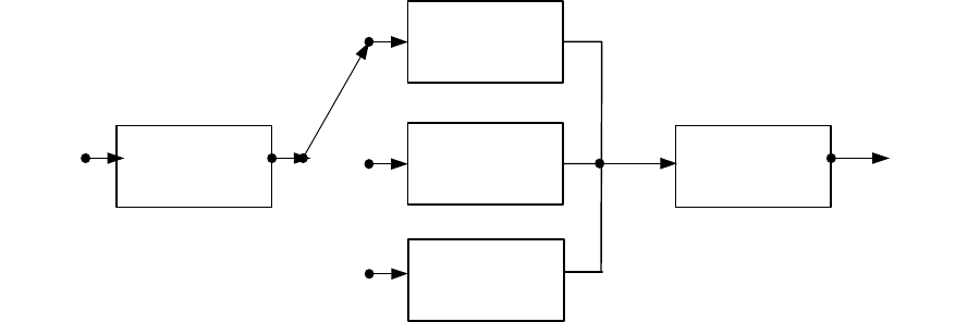
transform is permitted with sampling rates of 48 kHz, 32 kHz, 24 kHz and 16 kHz.
Each AU (audio frame) contains samples for 20 ms, 30 ms, 40 ms or 60 ms
respectively. In order to provide a similar architectural model to Layer II audio,
simple synchronisation and minimal re-tuning delay (i.e. station selection, or
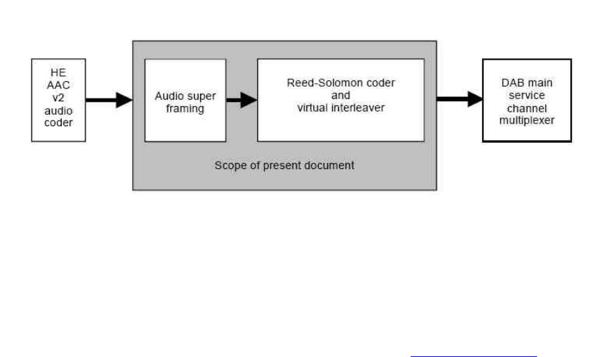
“zapping” time), AUs are built into audio super frames of 120 ms which are then
carried in five DAB logical frames. In order to provide additional error control, Reed
Solomon coding and virtual interleaving is applied. The overall scheme is shown in
Figure 4.3.
DIGITAL RADIO GUIDE TERRESTRIAL TRANSMISSION SYSTEMS - DAB
31
Figure 4.3: Conceptual diagram of the outer coder and interleaver
For generic audio coding, a subset of the MPEG-4 High Efficiency Advanced Audio
Coding v2 (HE AAC v2) toolbox - chosen to best suit the DAB system environment
- is used. Some additional tool specifications have been applied to optimise
performance for the broadcast environment of DAB digital radio.
More details can be found on the WorldDAB websites at www.worldDAB.com.
4.2.7 Types of Receivers
A selection of DAB digital radios has been on the market since 1999 in models for the
home, the car and the PC. Handheld radios also entered the market in 2003 with
competitively priced models for radio listeners on the move. Stations can also be
accessed using a PC equipped with a suitable receiver/decoder card.
Availability of DAB digital radios varies from country to country where DAB is available.
Department stores, independent retailers, supermarkets and multiples in most major
cities in the UK carry a wide range of receivers representing a mature retailer market
scenario. In the UK there are nearly 150 products in the market rising to around 200
products by the end of 2005. In Germany, Belgium, Nordic countries and Singapore, DAB
is becoming available via specialist stores, independent retailers and some department
stores in small quantities, and in Italy through manufacturers’ catalogues. In Spain and
France, receivers can be ordered and delivered on demand.
Prices of digital radios were high at first, but as with most new technologies, over time,
prices have fallen dramatically. Receiver prices vary from country to country, so it is
impractical to present specific price points within this guide. However, DAB digital radios
can now be found retailing from €60. A price guide is available from the WorldDAB
Project Office, on request, on the WorldDAB website, www.worlddab.org/dabprod.aspx.
Models delivering additional features have also been developed, with rewind, pause,
record functionality and Electronic Programme Guide (EPG) already integrated in some
models.
DIGITAL RADIO GUIDE TERRESTRIAL TRANSMISSION SYSTEMS - DAB
32
(1) In-Home Receivers
With launch prices high in 1999 and very little broadcast content available, take-up
was predictably slow, and product was initially stocked only by a handful of
specialist retailers. Today, a wide range of manufacturers have joined the market,
and costs have fallen significantly. New players have joined the DAB Digital Radio
family with many different models, including both mains and battery powered
portable units.
(2) In-Car Receivers
DAB Digital Radio was originally designed for mobile reception and so forms a
natural alliance with the in-car radio market. Manufacturers have been quick to
realise the potential of DAB Digital Radio on the move and no less than eight
companies are currently making a range of products to suit all tastes and pockets.
Most manufacturers have established a low to mid-range price point for the in-car
digital radio package and some manufacturers are offering line-fit options. For the
audio enthusiast there are more expensive products on offer.
In 2005, most car manufacturers started offering DAB as upgrade option (General
Motors, Ford, Volvo, Audi, Volkswagen, Jaguar, Land Rover, Mitsubishi, Renault
and DaimlerChrysler). Vauxhall and General Motors offer DAB as standard on UK
models, with plans to rollout in Europe. In 2006/07, many manufacturers are
planning standard fit of DAB on various models.
(3) Handheld Receivers
DAB technology and advances in silicon technology have led to the development of
DAB handheld and pocket radios. Manufacturers have moved quickly to produce
handheld products for the DAB market and the majority of them have established a
low to mid-range price point.
(4) PC Receivers
Alongside in-home, in-car and handheld equipment, DAB Digital Radio can also be
enjoyed at home and at work using a personal computer. Several devices were on
the market up until 2004, allowing the consumer to tune into DAB stations via either
a desktop unit or a laptop, but without the need for an Internet connection. DMB
enabled laptops and USB devices are also being developed enabling the possibility
of DAB PCs.

DIGITAL RADIO GUIDE TERRESTRIAL TRANSMISSION SYSTEMS - DAB
33
Table 4.2: List of manufacturers and their DAB products
Type of ReceiverReceiver
Manufacturer
Portable
Tuner/ Hi-Fi
In-Car
Hand-Held
PC
Website
Acoustic Solutions v v www.acousticsolutions.co.uk
Alba Radios Limited v
Albrecht v v www.albrecht-online.de
Alpine v v www.alpine-europe.com
Arcam v www.arcam.co.uk
Arion Technology v v www.arion.co.kr
Audionet v www.audionet.de
Bang & Olufsen v www.bang-olufsen.com
Blaupunkt v www.blaupunkt.de
BT v www.shop.bt.com
Bush Digital v v v www.bushdigital.co.uk
Cambridge Audio v www.cambridgeaudio.com
Clarion v www.clarion.co.uk
Crown v www.crowncorporation.co.uk
Cymbol v www.cymbol-hifi.co.uk
ELANsat v www.elansat.com
Eltax Ltd v www.eltax.com
Ferguson v v v
Genus Digital v v www.genusdigital.com
Goodmans v v v www.goodmans.co.uk
Grundig v v www.grundig.com
Harman Kardon v www.harman.com
Hitachi v v www.hitachi.com
Homecast Europe v www.homecast.de
Intempo Digital v www.intempo-digital.co.uk
iTech Dynamic v www.itechdynamic.com
JVC v v www.jdl.jvc-europe.com
Kenwood v www.kenwood.com
Kiiro v
Kiss v
Kjaerulff v www.kjaerulff1.com
LG Electronics v v v www.lge.com
M & G Audio v
Matsui v v
Maycom v v
Ministry of Sound vvvv www.shop.ministryofsound.com
Modular Technology v www.modulartech.com
Morphy Richards v www.morphyrichard.co.uk
DIGITAL RADIO GUIDE TERRESTRIAL TRANSMISSION SYSTEMS - DAB
34
Type of ReceiverReceiver
Manufacturer
Portable
Tuner/ Hi-Fi
In-Car
Hand-Held
PC
Website
Nevada v www.nevadaradio.co.uk
Onkvo v
Opel v www.opel.de
Orbit v www.orbitronics.com
Panasonic v v www.panasonic.de
Perstel v v v www.perstel.com
Philips v v v www.consumer.philips.com
Pioneer v www.pioneer-eur.com
Proline v
PURE Digital v v v www.pure-digital.com
Restek v www.restek.de
REVO Digital v www.revo.co.uk
Roadstar v www.roadstar.com
Roberts v v www.robertsradio.co.uk
Samsung v v v www.samsung.co.uk
Sangean v v www.sangean.nl
Sanyo v www.sanyo.com
Sharp v www.sharp.co.uk
Siemens VDO Automotive v www.3vdo.com
Sony v v v www.sony.co.uk
Steepletone v www.steepletone.com
TAGMcLaren v www.internationalaudiogroup.com
TEAC v v www.teac.co.uk
Technisat v v www.technisat.com
Terratec v v www.euro-tech.co.uk
Trinloc v v v v www.trinloc.de
VDO Dayton v www.vdodayton.de
The above list is not exhaustive; new products continuously come onto the market.
Highlighted cells indicate DMB products.
More information about the Eureka 147 system is included as Appendix A.
DIGITAL RADIO GUIDE TERRESTRIAL TRANSMISSION SYSTEMS - ISDB-TSB
35
4.3 Japan's Digital Radio Broadcasting (ISDB-TSB)
4.3.1 Overview
ISDB-TSB (Integrated Services Digital Broadcasting – Terrestrial for Sound
Broadcasting) system was developed for terrestrial Digital Sound Broadcasting (DSB)
and was included in the ITU-R Recommendation BS.1114-3 in 2004. The system
specification was developed by the Association of Radio Industries and Businesses
(ARIB) in October 1998. Laboratory experiments and field trials using Tokyo Tower were
carried out to verify the system performance in 1999 and the final specification was
approved as a Japanese Standard in November 1999.
Two stations were launched in Tokyo and Osaka in the frequency band 188 MHz to 192
MHz in October 2003.
4.3.2 The Methods
A terrestrial TV broadcasting frequency band that fits for mobile communications, OFDM
(Orthogonal Frequency Division Multiplexing) that withstands interference caused by
multiple paths (delayed waves), a modulation method that fits for communications with
cell phones and mobile receivers, powerful error correction function, etc., have been
adopted to allow good communications with cell phones and mobile receivers.
Concerning information compression technology and multiplexing technology, MPEG-2
has been adopted after diverse compatible communications with digital broadcastings
(such as terrestrial digital TV broadcasting, BS digital broadcasting, CS digital
broadcasting) were considered. MPEG-2 offers a common base for signal processing,
which leads to reduction in the production cost of receivers by using LSI-chip and
consolidation of receivers as well as easy exchange of data with other media.
Since this broadcasting system has the common segment structure with terrestrial digital
TV broadcasting, the receivers can be consolidated.
(1) Audio encoding system
MPEG-2 AAC (Advanced Audio Coding) and SBR (Spectral Band Replication)
have been adopted. However, SBR is optional.
This system satisfies the ITU-R standard, which enables high-quality multiple
channeling at a low bit rate of 144 kbps or so. It has been adopted by BS digital
broadcasting and terrestrial digital TV broadcasting. The adoption to the DSB
resulted from the consideration of cross-media communications.
(2) Restricted reception system
MULTI2 system has been adopted.
A scramble system has been adopted for charged broadcasting. It is the MULTI2
system that has already been adopted for terrestrial digital TV broadcasting, BS
digital broadcasting, and CS digital broadcasting. The adoption to the DSB resulted
DIGITAL RADIO GUIDE TERRESTRIAL TRANSMISSION SYSTEMS - ISDB-TSB
36
from the consideration of cross-media communications. Introduction of charged
broadcasting depends on the result after the feasibility is examined.
(3) Multiplexing System
MPEG-2 system has been adopted, therefore various digital contents such as
sound, text, still picture, moving picture and data can be transmitted simultaneously.
In addition, cross-media communications were considered because MPEG-2
system has been adopted in terrestrial digital TV broadcasting, BS digital
broadcasting and CS digital broadcasting.
(4) Transmission channel encoding system
Modulation method
OFDM method that withstands interference with multiple paths has been adopted.
One of DQPSK (Differential Quadrature Phase Shift Keying), QPSK, 16 QAM
(Quadrature Amplitude Modulation), and 64 QAM can be used. Since different
forms of broadcasting are expected, parameters are available for setting carrier
modulations and coding rate of inner code.
Error correction system
Reed solomon (204, 188) for external signalling and convolution coding
(convolution rates: 1/2, 2/3, 3/4, 5/6, 7/8) for internal signalling have been adopted.
The adoption resulted from the consideration of high coding efficiency and high
burst error correction capability for external signalling, various options of coding
rates for internal signalling and cross-media communications.
According to the broadcaster's purpose, they can select the carrier modulation
method, error correction coding rate, etc., of the system. The TMCC (Transmission
and Multiplexing Configuration Control) carrier transmits the information to the
receiver pertaining to the kind of modulation method and coding rate used in the
system.
(5) Transmission bandwidths
A transmission bandwidth that uses one OFDM segment of 6/14 MHz (approx. 429
kHz) bandwidth has been primarily adopted. In addition, a transmission bandwidth
that uses three OFDM segments is also available.
Figure 4.4 shows ISDB-TSB and full-band ISDB-T transmission concept and its
reception.
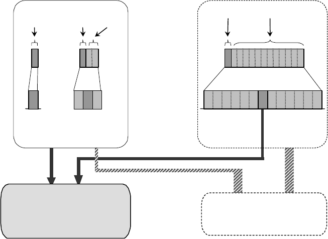
DIGITAL RADIO GUIDE TERRESTRIAL TRANSMISSION SYSTEMS - ISDB-TSB
37
Figure 4.4: ISDB-TSB and full-band ISDB-T transmission
concept and its reception
(6) Hierarchical transmission and partial reception
In the triple-segment transmission, both one layer transmission and hierarchical
transmission can be achieved. There are two layers of A and B in the hierarchical
transmission. The transmission parameters of carrier modulation scheme, coding
rates of the inner code and a length of the time interleaving can be changed in the
different layers.
The centre segment of hierarchical transmission is able to be received by single-
segment receiver. Owing to the common structure of OFDM segment, single-
segment receiver can partially receive a centre segment of full-band ISDB-T signal
whenever an independent program is transmitted in the centre segment.
Figure 4.5 shows an example of hierarchical transmission and partial reception. In
Japan, hierarchical transmission mode has to be used in the case of triple-segment
transmission.
Spectra
Data
Segment
ISDB-T transmission
ISDB-TSB Receiver
(Single-/triple-segment)
Sound / Data HDTV
/ Data
Sound
/ Data
Sound
/ Data
ISDB-TSB transmission
ISDB-T Receiver
(full-band:13-segments)
Partial reception
Sound
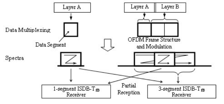
DIGITAL RADIO GUIDE TERRESTRIAL TRANSMISSION SYSTEMS - ISDB-TSB
38
Figure 4.5: Example diagram of hierarchical transmission
and partial reception
(7) Connected transmission
Efficient transmission
Connected transmission is defined as a transmission of multiple segments (e.g.,
multiple programs) from the same transmitter with no guard band.
In addition, the channels of independent broadcasters can be transmitted together
without guard bands from the same transmitter as long as the frequency and bit
synchronisation are kept the same between the channels.
But broadcasters can have their own RF channel in which they can select
transmission parameters independently.
The following two advantages are available from connected transmission:
•Facility and maintenance costs are low because only a single broadcasting
facility is required.
•Effective use of the frequency is enabled because no guard band between
segments is required.
The connected transmission technique is in operation for the first time in the world.
An example of connected transmission for three TS’s (TS1, TS2, and TS3) is
shown in Figure 4.6. Each TS signal is independently channel-coded. After OFDM-
frame adaptation, all segments symbol data are adapted for OFDM-signal
generation by single IFFT.
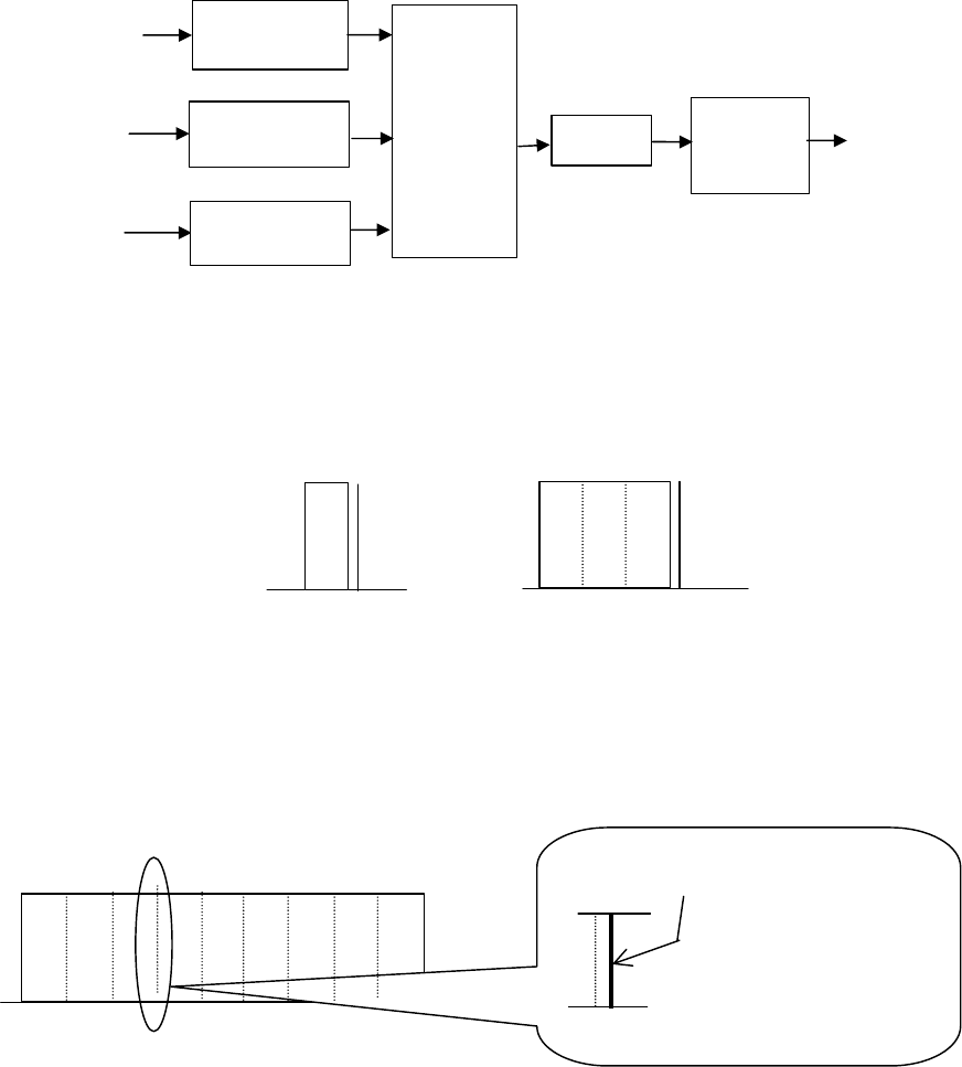
DIGITAL RADIO GUIDE TERRESTRIAL TRANSMISSION SYSTEMS - ISDB-TSB
39
Figure 4.6: Example of connected transmission (three TS’s)
Figure 4.7: CP carrier in an ordinary transmission
Figure 4.8: CP carrier in connected transmission
Parameter restrictions in connected transmission
The same mode should be applied for all segments. Mode means an identification
of transmission mode based on the carrier spacing of OFDM carriers.
The same guard interval length must be used for segments. Because all OFDM
symbols in connected transmission should be synchronised with each other,
modes having different symbol lengths cannot be mixed.
The first carrier of the upper adjacent
segment is substituted for CP.
CP
(a) 1-segment format
CP
(b) 3-segment format
TS1
TS2
TS3
OFDM
Frame
OFDM Frame
Adaptation
OFDM Frame
Adaptation
IFFT-
Input
adaptation IFFT Guard
interval
Insertion

DIGITAL RADIO GUIDE TERRESTRIAL TRANSMISSION SYSTEMS - ISDB-TSB
40
(8) Transmission capacities
The transmission capacities of the single-segment and the triple-segment are
shown in Table 4.3 and 4.4 respectively.
Table 4.3: Information bit rates for
the single-segment transmission (Segment BW=6/14MHz)
Information Rates (kbps)
Carrier Modulation Convolutional Code Guard
Interval
Ratio 1/4
Guard
Interval
Ratio 1/8
Guard
Interval
Ratio 1/16
Guard
Interval
Ratio 1/32
1/2 280.85 312.06 330.42 340.43
DQPSK 2/3 374.47 416.08 440.56 453.91
3/4 421.28 468.09 495.63 510.65
QPSK 5/6 468.09 520.10 550.70 567.39
7/8 491.50 546.11 578.23 595.76
1/2 561.71 624.13 660.84 680.87
2/3 748.95 832.17 881.12 907.82
16QAM 3/4 842.57 936.19 991.26 1021.30
5/6 936.19 1040.21 1101.40 1134.78
7/8 983.00 1092.22 1156.47 1191.52
1/2 842.57 936.19 991.26 1021.30
2/3 1123.43 1248.26 1321.68 1361.74
64QAM 3/4 1263.86 1404.29 1486.90 1531.95
5/6 1404.29 1560.32 1652.11 1702.17
7/8 1474.50 1638.34 1734.71 1787.28
Table 4.4: Information bit rates for the triple-segment transmission*5
Information Rates (kbps)
Carrier Modulation Convolutional Code Guard
Interval Ratio
1/4
Guard
Interval Ratio
1/8
Guard
Interval Ratio
1/16
Guard
Interval Ratio
1/32
1/2 0.842 0.936 0.991 1.021
DQPSK 2/3 1.123 1.248 1.321 1.361
3/4 1.263 1.404 1.486 1.531
QPSK 5/6 1.404 1.560 1.652 1.702
7/8 1.474 1.638 1.734 1.787
1/2 1.685 1.872 1.982 2.042
2/3 2.246 2.496 2.643 2.723
16QAM 3/4 2.527 2.808 2.973 3.063
5/6 2.808 3.120 3.304 3.404
7/8 2.949 3.276 3.469 3.574
1/2 2.527 2.808 2.973 3.063
2/3 3.370 3.744 3.965 4.085
64QAM 3/4 3.791 4.212 4.460 4.595
5/6 4.212 4.680 4.956 5.106
7/8 4.423 4.915 5.204 5.361
5 In the case of the triple-segment transmission, information rate can be calculated by the combination of segment
information rates.
DIGITAL RADIO GUIDE TERRESTRIAL TRANSMISSION SYSTEMS - ISDB-TSB
41
4.3.3 Characteristics
(1) More channels
Terrestrial TV broadcasting will be discontinued in July 2011. However, in the case
of radio, existing AM, FM, and SW analog services are expected to continue, thus
digital radio is being positioned as an opportunity to provide more channels.
(2) Consortium
At present, digital radio broadcasting is operated by a consortium where
corporations interested in digital radio broadcasting have participated. The official
name of the consortium is a corporate judicial body called the Association for
Promotion of Digital Broadcasting or the DRP (Digital Radio Promotion) for short.
The establishment of the consortium was permitted by the Ministry of Internal
Affairs and Communications. The DRP has two offices, in Tokyo and Osaka. The
operation fund is provided by the member companies. Members include NHK,
radio stations, TV stations, data broadcasting companies, trading companies,
automakers and other companies interested in digital radio in the private sector.
Over 70 organizations and companies have joined the consortium throughout
Japan.
The objectives of the DRP are as follows:
•Implementation of experimental broadcasting for practical application
•Development of broadcasting services
•Research and study on trends in demand
•Promotion and spread of reception
(3) Experimental broadcasting for practical application
The DRP is the only corporate judicial body licensed. Its experimental stations are
located in Tokyo and Osaka. The broadcasting facilities are owned and operated
by the DRP.
4.3.4 Receivers
(1) Receiver test centre
A receiver test centre has been installed in the DRP office to check the operation of
receivers and to support development efforts.
The major activities are as follows:
•To define and revise a specification for standard test streams, and print and
distribute its copies
•To make connection experiment items and connection manuals, and distribute
its copies
DIGITAL RADIO GUIDE TERRESTRIAL TRANSMISSION SYSTEMS - ISDB-TSB
42
•To define a specification for transmission signals on experimental radio waves
•To operate experimental radio waves and to publicize operation schedules
(2) Trial receivers
At present, no receivers are sold in the commercial market.
Thus, different types of trial receivers were developed for the use of experimental
hearing.
Trial receivers include PC-card receivers that have an antenna on the top of a
PCMCIA card, portable receivers (1-segment only) for the DRP, and PDA
(Personal Digital Assistant) receivers where a digital radio adapter is mounted.
(3) Receivers expected
In addition to the above mentioned trial receiver types, the following types of
receivers can be expected:
•cell phone type receivers
•ordinary and smaller palmtop type receivers
•car stereo type receivers for mobiles, and so on
4.3.5 Overview of Services
Among the current services being broadcast, the following types of contents are unique
to digital radio broadcasting.
(1) Multiple voice broadcasting
Listeners can choose a news item, foreign language course, cooking program, etc.,
in addition to multiple-language concurrent broadcasting of weather forecast and
stories.
(2) 5.1 surround broadcasting
5.1 surround broadcast is being provided which includes still images and textual
information linked to its programs, for example, photos during performances in a
live concert.
DIGITAL RADIO GUIDE TERRESTRIAL TRANSMISSION SYSTEMS - ISDB-TSB
43
(3) Broadcasting of simplified moving images
Actions of a DJ in a studio booth, music promotion images or so are being
broadcast linked to the programs.
(4) Download service experiment
With the interactive function of cell phones and PDAs, experiments are being
provided, including sales of tickets and CDs, and tallying up of questionnaires.
Such experiments also include download service of music titles that were
broadcast.
4.3.6 Outlook for the Future
At present, digital radio broadcast experiments for practical application are underway
through providing different contents of services and operation forms.
The following subjects must be handled successfully for the spread and development of
digital radio broadcasting:
•To transfer the experimental broadcasting into actual broadcasting and to expand
service areas
•Early release of receivers in the commercial market
•Early start of services in major cities in Japan
•Nationwide deployment of digital radio broadcasting after 2011, when analogue TV
broadcasting comes to ends and frequency re-allotments are completed

DIGITAL RADIO GUIDE TERRESTRIAL TRANSMISSION SYSTEMS - HD RADIO
44
4.4 iBiquity HD Radio System
The HD Radio system developed by US-based iBiquity Digital was designed for regions
where limited spectrum prevents the allocation of new frequencies for digital broadcasting.
The HD Radio system allows broadcasters to simultaneously transmit an analogue and
digital signal without the need for additional spectrum for the digital signal. The HD Radio
system takes advantage of unused portions of the spectrum on either side of the
analogue carrier (as defined by the service frequency allocation “mask”) and implements
frequency re-use by including digital carriers in quadrature to the existing analogue
carrier. In either case, the analogue signals are in close proximity to the digital signals
and great care must be taken to prevent unwanted interference between them.
The HD Radio system is designed to work in hybrid mode (compatible analogue and
digital) as well as to migrate to an all-digital system once analogue radios have been
largely replaced in the future. See Figures 4.10, 4.11, and 4.12.
The HD Radio system offers a number of advantages for broadcasters, consumers and
regulators. The HD Radio system replicates the existing coverage patterns of each radio
station thereby retaining the existing economic value of the station. Broadcasters can
convert to digital broadcasts with a relatively modest investment and retain the vast
majority of their existing physical plant. In addition, the introduction of the digital signal in
the existing channel allows the broadcaster to retain the station’s existing dial position.
Because the system supports simulcast of the analogue and digital signals, consumers
are able to upgrade to digital over an extended period, taking into account normal
equipment replacement cycles. Regulators benefit because there is no need for
spectrum allocations or licensing of new stations. However, many countries are cautious
about IBOC technology because it has the potential in certain circumstances to cause
some degradation to existing analogue services, particular at the edge of the existing
analogue service area.
The HD Radio system offers the following features:
•CD quality audio in the FM-band and FM quality stereo audio in the AM band.6
•Digital coverage nearly equivalent to existing analogue coverage. In areas where the
digital signal is lost, the system automatically blends to the analogue back-up signal
to ensure coverage is never less than existing coverage.
•Advanced coding technologies and time diversity between the analogue and digital
signals ensure a robust signal.
•The FM system has demonstrated significant robustness in the presence of severe
multipath, and the AM system has demonstrated significant robustness in the
presence of impulse noise.
•The FM system offers options for introducing new data services ranging from 1 to
300 kbps depending on the mode of operation.
The HD Radio system has been tested in North and South America. It is currently in
operation in approximately 250 stations throughout the United States and is expected to
be in use by approximately 650 stations by the end of 2005.
6See the Report of the National Radio Systems Committees, DAB Subcommittee Evaluation of the iBiquity Digital
Corporation System Part 1 – FM IBOC, November 29, 2001 (“FM NRSC Report”) and Part 2, AM IBOC, dated April 6,
2002 (“AM NRSC Report”).

DIGITAL RADIO GUIDE TERRESTRIAL TRANSMISSION SYSTEMS - HD RADIO
45
4.4.1 HD Radio Standards Activity
Both the AM and FM HD Radio systems have received international endorsements as
well as endorsements in the United States. The AM HD Radio system is included in
Recommendation ITU-R BS.1514-1, adopted October 2002 where it is classified as the
“IBOC DSB System.” The FM HD Radio system is included in Recommendation ITU-R
BS.1114-4, adopted May 2003 where it is classified as “Digital System C.” In the United
States, the Federal Communications Commission (FCC) endorsed both the AM and FM
HD Radio systems on October 10, 2002. 7 Moreover, the National Radio Systems
Committee (NRSC), an industry standards setting body sponsored by the National
Association of Broadcasters and the Consumer Electronics Association, endorsed the FM
HD Radio system in a report dated November 29, 20018and the AM HD Radio system in
a report dated April 6, 2002.9 The NRSC endorsement was an outgrowth of an extensive
testing program of both the AM and FM HD Radio systems. The NRSC supervised
independent testing of the HD Radio system in both the laboratory and in the field under
a comprehensive set of conditions. The tests were designed to assess both the
performance of the digital system as well as the compatibility of the digital system with
existing analogue operations in the AM and FM bands. In the laboratory, the digital
system was subjected to a range of conditions associated with typical broadcasts in the
AM and FM band. For example, the FM system was tested in the presence of multiple
forms of multipath interference as well as numerous examples of co-channel and
adjacent channel interference. In the case of AM, the digital system was tested in the
presence of impulse noise in addition to the typical co-channel and adjacent channel
interference associated with the AM band.
Field tests were conducted using commercial AM and FM stations selected for their
characteristics in terms of interference from adjacent channel stations as well as to
represent a variety of antenna and implementation configurations. For both the
laboratory and field tests, objective measurements were recorded and considered in the
evaluation process. In addition, thousands of audio samples were produced and used to
conduct an extensive subjective evaluation process. General population listeners were
asked to rate a variety of sound samples from the laboratory and field tests to assess the
real world response to the introduction of the HD Radio system. The test results
demonstrated that the HD Radio system consistently outperformed existing analogue AM
and FM radio. Moreover, the tests established that the introduction of the HD Radio
system will not cause harmful interference to existing analogue broadcasts in the vast
majority of cases. In those cases where new interference is expected to occur, it is
expected that new interference will be most common in peripheral areas outside the core
coverage areas of a station. The NRSC concluded that this minimal risk of additional
interference is more than outweighed by the improved audio quality and performance that
the HD Radio system repeatedly demonstrated throughout the test programme.10
4.4.2 HD Radio AM and FM Receivers
HD Radio receivers are inherently simpler and lower cost than new band receivers since
much of the circuitry required for the digital signals is common to that used to process the
7Digital Audio Broadcasting Systems And Their Impact on the Terrestrial Radio Broadcast Service, MM Docket No. 99-
325, First Report and Order (October 10, 2002).
8DAB Subcommittee Evaluation of the iBiquity Digital Corporation IBOC System Part 1 – FM IBOC dated November 29,
2001 (“NRSC FM Report”).
9DAB Subcommittee Evaluation of the iBiquity Digital Corporation IBOC System Part 2 – AM IBOC dated April 6, 2002
(“NRSC AM Report”).
10 See NRSC FM Report at 9; NRSC AM Report at 8.
DIGITAL RADIO GUIDE TERRESTRIAL TRANSMISSION SYSTEMS - HD RADIO
46
existing analogue signal. As a result, HD Radio receivers are expected to cost no more
than 20% more than existing analogue receivers.
Figure 4.9 - Typical HD Radio Automobile Receivers
The first phase of the HD Radio receiver roll out is focusing on automobile and home hi-fi
receivers. Aftermarket automobile receivers and home receivers began reaching the
market in early 2004. OEM automobile receivers are scheduled to be introduced for the
automobile model year 2006, which should be launched in the third quarter of 2005.
Figure 4.9 shows fully functional automobile receivers designed to fit into the standard
car mount frames.
Along with the introduction of second and third generation HD Radio semiconductors,
featuring lower power consumption and cost during the two or three years after the initial
receiver introduction, portable and lower cost receiver products are expected to be
introduced.
4.4.3 HD Radio System Technical Design Overview
The HD Radio system is designed to permit a smooth evolution from current analog
Amplitude Modulation (AM) and Frequency Modulation (FM) radio to a fully digital In-
Band On-Channel (IBOC) system. This system can deliver digital audio and data services
to mobile, portable, and fixed receivers from terrestrial transmitters in the existing
Medium Frequency (MF) and Very High Frequency (VHF) radio bands. The system is
designed to allow broadcasters to continue to transmit analog AM and FM simultaneously
with new, higher-quality and more robust digital signals, allowing broadcasters and their
listeners to convert from analog to digital radio while maintaining each station’s current
frequency allocation.
The HD Radio system allows a broadcast station to offer multiple services. A service can
be thought of as a logical grouping of application data identified by the HD Radio system.
Services are grouped into one of two categories:
Core Services:
•Main Program Service (both Audio (MPA) and Data (PAD))
•Station Information Service (SIS)
•Advanced Application Services (AAS)
DIGITAL RADIO GUIDE TERRESTRIAL TRANSMISSION SYSTEMS - HD RADIO
47
The flow of service content through the HD Radio broadcast system is as follows:
•Service content enters the HD Radio broadcast system via Service Interfaces;
•Content is assembled for transport using a specific protocol;
•It is routed over logical channels via the Channel Multiplex; and
•It is waveform modulated via the Waveform/Transmission System for over-the-air
transmission.
The system employs coding to reduce the sampled audio signal bit rate and baseband
signal processing to increase the robustness of the signal in the transmission channel.
This allows a high quality audio signal plus ancillary data to be transmitted in adjacent
frequency partitions and at low levels that do not interfere with the existing analog signals.
4.4.4 Core Services
(1) Main Program Service (MPS)
The Main Program Service (MPS) is a direct extension of traditional analog radio.
MPS allows the transmission of existing analog radio-programming in both analog
and digital formats. This allows for a smooth transition from analog to digital radio.
Radio receivers that are not HD Radio enabled can continue to receive the
traditional analog radio signal, while HD Radio receivers can receive both digital
and analog signals via the same frequency band. In addition to digital audio, MPS
includes digital data related to the audio programming. This is also referred to as
Program Associated Data (PAD).
(2) Station Information Service (SIS)
The Station Information Service (SIS) provides the necessary radio station control
and identification information, such as station call sign identification, time and
location reference information. SIS can be considered a built-in service that is
readily available on all HD Radio stations. SIS is a required HD Radio service and
is provided dedicated bandwidth.
(3) Advanced Application Services (AAS)
Advanced Application Services (AAS) is a complete framework in which new
applications may be built. In addition to allowing multiple data applications to share
the Waveform/ Transmission medium, AAS provides a common transport
mechanism as well as a unified Application Programming Interface (API). On the
transmission side, broadcasters utilize the common AAS interface to insert
service(s) into their signal; receiver manufacturers utilize the AAS ‘toolkit’ to
efficiently access these new services for the end-user. AAS includes separate
audio programming such as reading services and other secondary aural and data
services.
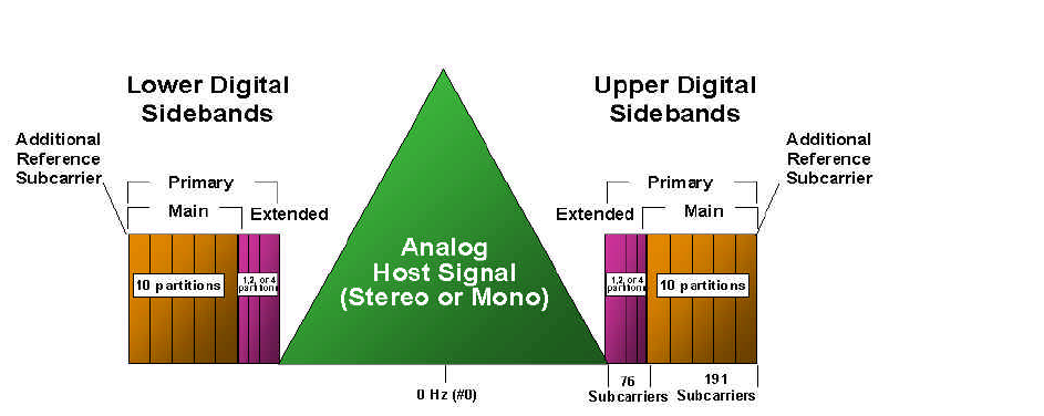
DIGITAL RADIO GUIDE TERRESTRIAL TRANSMISSION SYSTEMS - HD RADIO
48
(4) Waveforms and Spectra
The HD Radio system provides a flexible means of transitioning to a digital
broadcast system by providing three new waveform types: Hybrid, Extended Hybrid,
and All Digital. The Hybrid and Extended Hybrid types retain the analogue FM
signal, while the All Digital type does not.
All three waveform operate well below the allocated spectral emissions mask as
currently defined by the United States Federal Communications Commission.
The digital signal is modulated using orthogonal frequency division multiplexing
(OFDM). OFDM is a parallel modulation scheme in which the data stream
modulates a large number of orthogonal subcarriers, which are transmitted
simultaneously. OFDM is inherently flexible, readily allowing the mapping of logical
channels to different groups of subcarriers.
(5) Hybrid Waveform
The digital signal is transmitted in sidebands on either side of the analog FM signal
in the Hybrid waveform. The power level of each sideband is approximately 23 dB
below the total power in the analog FM signal. The analog signal may be
monophonic or stereo, and may include subsidiary communications authorization
(SCA) channels. See Figure 4.10.
Figure 4.10: Hybrid spectrum allotment of FM HD Radio system
Extended Hybrid operation involves use of us to four Extended Partitions in
addition to the 10 Main Partititions.
(6) FM Extended Hybrid Waveform
In the Extended Hybrid waveform, the bandwidth of the Hybrid sidebands can be
extended toward the analogue FM signal to increase digital capacity. This
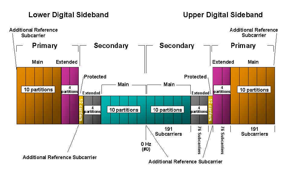
DIGITAL RADIO GUIDE TERRESTRIAL TRANSMISSION SYSTEMS - HD RADIO
49
additional spectrum, allocated to the inner edge of each primary sideband, is
termed the primary extended sideband. See Figure 4.10.
(7) FM All Digital Waveform
The greatest system enhancements are realized with the All Digital waveform, in
which the analogue signal is removed and the bandwidth of the primary digital
sidebands is fully extended as in the Extended Hybrid waveform. In addition, this
waveform allows lower-power digital secondary sidebands to be transmitted in the
spectrum vacated by the analogue FM signal. Approximately 300 kbps of data is
available in All Digital mode. See Figure 4.11.
Figure 4.11 - All digital spectrum allotment of FM HD Radio system
(8) AM Hybrid and All Digital Waveforms
Unlike the FM HD Radio system, the AM system contains no extended hybrid
capacity. The allocation scheme is represented in Figure 4.12.
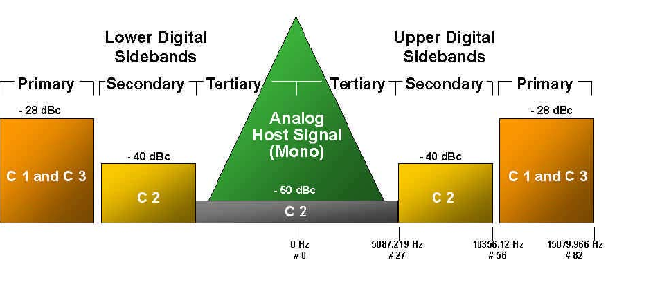
DIGITAL RADIO GUIDE TERRESTRIAL TRANSMISSION SYSTEMS - HD RADIO
50
Figure 4.12: Hybrid AM HD Radio system spectrum allotment
4.4.5 HD Radio Subsystems
A basic block diagram representation of the system is shown in Figure 4.13. It represents
the HD Radio digital radio system as three major subsystems:
•Audio source coding and compression
•Transport and Service Multiplex
•RF/Transmission
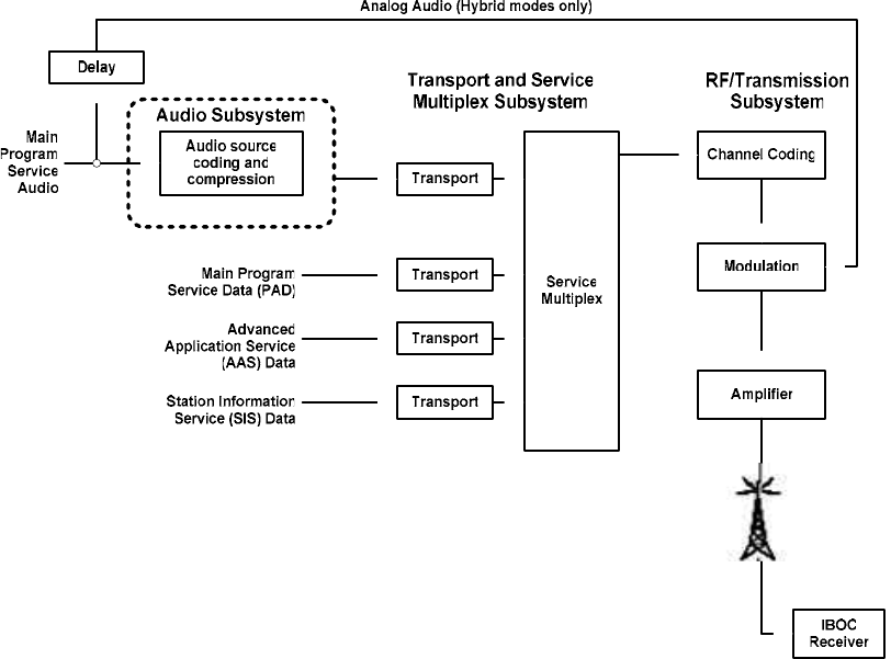
DIGITAL RADIO GUIDE TERRESTRIAL TRANSMISSION SYSTEMS - HD RADIO
51
Figure 4.13: Functional Block Diagram of HD Radio System
(1) Audio Source Coding and Compression
The Audio subsystem performs the source coding and compression of the sampled
digitized Main Program Service (MPS) Audio program material. “Source coding and
compression” refers to the bit rate reduction methods, also known as data
compression, appropriate for application to the audio digital data stream. In hybrid
modes, the MPS Audio is also analog modulated directly onto the carrier for
reception by conventional analog receivers. Several categories of data may also be
transmitted on the digital signal including station identification, messages related to
the audio program material, and general data services.
(2) Transport and Service Multiplex
“Transport and service multiplex” refers to the means of dividing the digital data
stream in “packets” of information, the means of uniquely identifying each packet or
packet type (data or audio), and the appropriate methods of multiplexing audio data
stream packets and data stream packets into a single information stream. The
transport protocols have been developed specifically to support data and audio
transmission in the AM and FM radio bands. The IBOC transport is modelled
loosely on ISO 7498 standard.
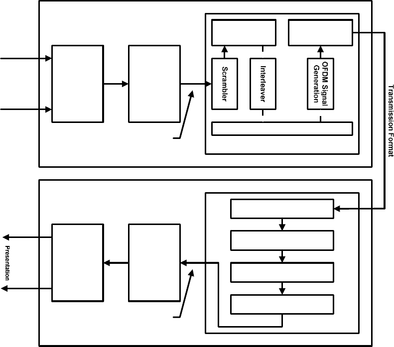
DIGITAL RADIO GUIDE TERRESTRIAL TRANSMISSION SYSTEMS - HD RADIO
52
(3) RF/Transmission System
“RF/Transmission” refers to channel coding and modulation. The channel coder
takes the multiplexed bit stream and applies coding and interleaving that can be
used by the receiver to reconstruct the data from the received signal, which
because of transmission impairments, may not accurately represent the transmitted
signal. The processed bit stream is modulated onto the OFDM subcarriers that are
transformed to time domain pulses, concatenated, and up-converted to the FM
band.
Figure 4.14: Block diagram of HD Radio transmission and reception multiplexing
7UDQVSRUW
DQG 0 X OWLSOH[
$ SSOLFDWLRQ
( QFRGHUV
$ XGLR
'DWD
7UDQVP LWWHU
XGLR
DWD
5 HFHLYHU
$ SSOLFDWLRQ
' HFRGHUV
&KDQQHO
( QFRGLQJ
2)' 0 6XEFDUULHU 0DSSLQJ
7UDQVI HU
)UDP HV
7UDQVP LVVLRQ
6\ VWHP
0 RGHP
7UDQVSRUW
DQG
'HPXOWLSOH[
7UDQVI HU
)UDP HV
2)' 0 ' HPRGXODWRU
'HLQWHUOHDYHU
&KDQQHO 'HFRGHU
' HVFUDP E OHU
0 RGHP
4.4.6 Receiver Systems
A functional block diagram of an HD Radio receiver is presented in Figure 4.15. The
signal is received by the antenna, passed through an RF front end, and mixed to an
intermediate frequency (IF), as in existing analogue receivers. Unlike typical analogue
receivers, however, the signal is then digitised at IF, and digitally down-converted to
produce in-phase and quadrature base band components. The hybrid signal is then
separated into an analogue component and a digital component. The analogue FM
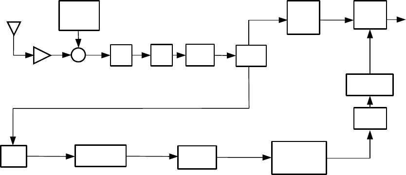
DIGITAL RADIO GUIDE TERRESTRIAL TRANSMISSION SYSTEMS - HD RADIO
53
stereo signal is digitally demodulated and demultiplexed by the FM receiver to produce a
sampled, stereo audio signal.
The base band digital signal is first sent to the modem, where it is processed by the First
Adjacent Cancellation system to suppress interference from potential first-adjacent
analogue FM signals. The signal is then OFDM demodulated, deframed, and passed to
the FEC decoding and deinterleaving function. The resulting bit stream is processed by
the codec function to decompress the source-encoded digital audio signal. This digital
stereo audio signal is then passed to the blend function.
Figure 4.15: FM hybrid IBOC receiver functional block
FM
Isolation
FAC QPSK/OFDM
Demodulator Deframe
FM+DAB
sampled analogue FM
Audio
Decoder
XBPF A/D DDC
FM
Stereo
Det
Tunable
LO
RF Front End 10.7 MHz IF
Audio
Diversity
Delay
Audio
Blend
FM
Stereo
DSB
Stereo
FEC Decode
and
De-interleave
4.4.7 Features Common to North American Digital Radio Systems
(1) Sound Quality
Sound quality of digital radio systems has improved dramatically in recent years
with progressively lower bitrates being shown in various applications as achieving
near CD quality. Rates well below 96 kbps are routinely utilized in digital radio
systems in operation in North America and meeting with wide customer acceptance.
(2) Multipath Resistance
OFDM based systems are made to be resistant to multipath within a guard interval.
In the case of the Eureka system, the guard interval is set to 62 ?s (18.6 km at the
speed of light). This means that any echoes coming from up to 18.6 km will be
considered as constructive to the signal. This allows the use of on-channel
repeaters (that are treated as active echoes).
Note also that some systems, such as the Eureka system, also use unequal error
protection and error concealment techniques. This allows for a graceful
degradation of the digital signal quality when fading occurs and allows for S/N
requirement reductions for the receiver. The Eureka system is especially noted for
achieving multipath free reception, but narrower bandwidth systems such as the
DIGITAL RADIO GUIDE TERRESTRIAL TRANSMISSION SYSTEMS - HD RADIO
54
HD Radio system have also been shown to be multipath-free even in challenging
propagation conditions.
(3) Frequency Response
It is difficult to evaluate the exact frequency response of a codec, because it will
change dynamically depending on the available bit rate and the difficulty of
encoding the instantaneous audio material. A quick example can be demonstrated
using a single carrier frequency sweep on any codecs. Typically total frequency
response of 20 kHz is measured in such tests, even at 16 kbps. On the other hand,
encoding a rich stereo program on the same codec at 16 kbps, may result in a pure
monophonic signal of less than 5 kHz.
Consequently, the codec has to be tailored to the program content being broadcast.
See Table 4.5 for MPEG Layer II implementation recommendations.
Table 4.5: Recommended MPEG II data and sampling rates
for various program material
Voice program: 48 kbps . 24 KHz Sampling rate / Mono
Mono program with music: 80 kbps / 48 KHz Sampling rate / Mono
Oldies music: 112 kbps / 48 KHz / Joint Stereo
(4) Audio Quality Ratings
The basic audio quality is defined by the codec used and the ruggedness of the
transmission channel. The performance quality of different codecs when critical
material is encoded has been measured as shown in Figure 4.16.
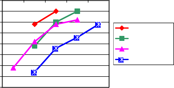
DIGITAL RADIO GUIDE TERRESTRIAL TRANSMISSION SYSTEMS - HD RADIO
55
Figure 4.16
-4
-3.5
-3
-2.5
-2
-1.5
-1
-0.5
0
64 96 128 160 192
kbps
MPEG AAC
Dolby AC3
Lucent PAC
MPEG L2
Source: Journal of the Audio Engineering Society, Vol. 46, No. 3, March 1998, p. 164.
Where the signal quality refers to the Subjective Difference Grade ITU scale (ITU-R
BS.562) as follows:
0 = Imperceptible
-1 = Perceptible but not annoying
-2 = Slightly annoying
-3 = Annoying
-4 = Very annoying
Not shown in the previous graph is the usage of the Sub-band replication (SBR)
technique. This technique allows for a higher coding efficiency by coding the lower
bands (up to 8 kHz to 12 kHz) using a basic codec (MPEG AAC, L2 or others) and
replicating the upper frequency using statistical and predictive information. This
technique usually demonstrates an increase in efficiency of up to 30% and it is
generally backward compatible with the source codec. The iBiquity Digital HDC
audio codec relies on SBR technology in achieving good results at 96 kbps and
lower.

DIGITAL RADIO GUIDE TERRESTRIAL TRANSMISSION SYSTEMS - HD RADIO
56
4.4.8 Infrastructure Requirements
At this writing, approximately 250 HD Radio stations have commenced operations in the
United States with an additional 300 stations currently licensed to commence operations
in the coming year. Consumer receivers went on sale in early 2004 and considerable
work has been done on implementation options that may significantly reduce installation
costs at many stations.
In particular, the use of separate antenna radiating systems has been successfully
demonstrated which can eliminate the need for combiners at higher power FM stations.11
Furthermore development of a “Gen-2” system12 that will multiplex the HD Radio data
stream at the studio site, much as is done with composite analogue STLs, is expected to
be introduced in the coming year. Low-level combining is preferred and has been shown
to be cost effective at power levels up to an analogue 7 kw transmitter power output.
11 See IBOC Space Diversity Testing, Talmadge Ball, Proceedings of NAB 2003 BEC; also see “Dual Antenna Report”
Denny & Associates at http://www.nab.org/scitech/fccfilingattachmentb.pdf.
12 Gen 2 refers to a planned evolution in HD system design that will permit multiplexing of all digital signals at the studio to
achieve significant reductions in feeder link bandwidth requirements.

DIGITAL RADIO GUIDE TERRESTRIAL TRANSMISSION SYSTEMS - HD RADIO
57
Deployment Status
Current deployment statistics for the HD Radio System in the United States are shown
below.
Figure 4.17: Deployment status of HD Radio
in the United States as of February 2005
570 Licensees
140 Markets
46 Top 50 Markets
212 Licensed Groups
18 Licensed Top 20
49 States Serviced*
* Includes Washington, DC and Puerto Rico
Population Served 198,000,000
Listeners Served 32,000,000
250 On The Air
71 Markets
37 Top 50 Markets
38 States Served
Population Served 150,000,000
Listeners Served 23,000,000
Rnk Market # On Rnk Market # On
1 New York 10 6 26 Cincinnati 10 8
2 Los Angeles 19 13 27 Sacramento, CA 5 0
3 Chicago 11 11 28 Riverside, CA 3 0
4 San Francisco 13 10 29 Kansas City, MO/KS 6 5
5 Dallas 5 1 30 San Jose, CA 3 2
6 Philadelphia 12 7 31 San Antonio, TX 0 0
7 Houston 3 1 32 Salt Lake City 2 0
8 Washington, DC 4 4 33 Milwaukee 2 2
9 Boston 15 10 34 Providence, RI 2 0
10 Detroit 17 15 35 Columbus, OH 3 2
11 Atlanta 16 11 36 Middlesex, NJ 3 0
12 Miami 18 8 37 Charlotte, NC 3 0
13 Puerto Rico 6 0 38 Orlando, FL 4 2
14 Seattle 10 9 39 Las Vegas 3 2
15 Phoenix 0 0 40 Norfolk, VA 3 1
16 Minneapolis 6 4 41 Indianapolis 12 9
17 San Diego 0 0 42 Austin, TX 2 1
18 Nassau-Suffolk 2 0 43 Greensboro, NC 0 0
19 Baltimore 4 1 44 New Orleans 4 2
20 St. Louis 5 4 45 Nashville 4 2
21 Tampa 1 1 46 Raleigh-Durham 3 1
22 Denver 17 9 47 West Palm Beach, FL 4 3
23 Pittsburgh 1 0 48 Memphis 1 1
24 Portland 12 6 49 Hartford, CT 5 1
25 Cleveland 4 2 50 Jacksonville, FL 2 1
Courtesy: iBiquity Digital
DIGITAL RADIO GUIDE TERRESTRIAL TRANSMISSION SYSTEMS - ISSUES
58
4.5 Issues related to Terrestrial Systems
4.5.1 Spectrum Availability
Government policies on frequency management and spectrum pricing affect all radio
broadcasting development. In some countries the radio spectrum is looked upon as a
means of raising revenue.
Administrations in different countries operate different policies, but there are common
threads. Whether frequencies are allocated through auctions or by other means,
spectrum is undeniably a scarce resource and especially so in the bands that are most
useful for digital audio broadcasting (including the existing shortwave bands, existing AM
and FM bands, as well as the upper VHF and L-Bands).
In many countries administrations have allocated spectrum for digital broadcasting, both
radio and TV.
The DRM system is designed to work within the existing band and channel structure for
all the broadcasting bands below 30 MHz. As such, its use of the spectrum conforms to
the Geneva Treaty of 1975 for ITU-R Regions 1 and 3, the long wave and medium wave
channels have a 9 kHz bandwidth, or multiples thereof, depending on the channel
assignment; the Rio Treaty of 1981 for Region 2 medium wave specifies a 10 kHz
bandwidth; and the shortwave channel bandwidth is 10 kHz for all the HF broadcasting
bands. Thus, no new spectrum is required. Furthermore, based upon ITU-R decisions
during 2003, DRM signals can be used operationally in these bands, with the existing
channel bandwidths, interspersed with the analogue broadcasts. That is, there are no
specially allocated segments of bands for digital transmissions. Ongoing testing has
verified the feasibility of this approach.
In the US, the government has approved HD Radio as a way to alleviate the need for
new spectrum to implement terrestrial digital radio.
The constraints and uncertainties that cloud the issue of frequency allocations for new
digital terrestrial services in the VHF and L-Bands are not such a problem for AM digital
developments. There is some prospect that the congestion now in the AM bands could
be reduced with digital broadcasting. Potentially, there is much to be gained from digital
broadcasting in the short-wave bands because current analog systems require a number
of simultaneous broadcasts to ensure reliable reception under changing ionospheric
conditions.
Case Study: Allocations in Region 1
In the UK, where spectrum is being allocated for seven Eureka 147 DAB multiplexes, the
granting of license has been in VHF Band III, which is very suitable for terrestrial DAB (T-
DAB) transmissions. Across Europe, both VHF and L-Band frequencies will be used for
T-DAB services. At a planning meeting held set up by the CEPT (European Conference
of Postal and Telecommunications Administrations and held in Wiesbaden) in 1995,
frequency blocks in three bands were considered:
•VHF Band I (47 – 68 MHz)
•VHF Band III (174-240 MHz)
•L-Band (1452 – 1467.5 MHz)
The Wiesbaden plan made allotments for digital audio broadcasting in VHF channels 11
and 12 and in the L-Band, and considered the implications of protecting non-DAB
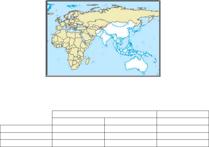
DIGITAL RADIO GUIDE TERRESTRIAL TRANSMISSION SYSTEMS - ISSUES
59
services within the planning area. These include airborne military services and television
services in the VHF bands as well as fixed and aeronautical telemetry in the L-Band.
Overall, there were sufficient allotments made in the Wiesbaden plan for the initial needs
of DAB, but looking ahead, additional frequency allocations will be needed in Europe.
Most organisations planning to launch today and expand T-DAB services favour VHF
frequencies.
The position on T-DAB frequencies in other parts of the world is similarly complicated
and underlines the point that frequency allocation is an outstanding issue that will remain
high on the DAB agenda for some time to come.
At the International Telecommunications Union (ITU) in Geneva, the Regional
Radiocommunications Conference 2006 (RRC-06) took place from 15 May to 16 June
2006. The new agreement, GE06, includes the frequency plans for T-DAB and DVB-T in
Band III and for DVB-T in Bands IV/V for Region 1 (parts of Region 1 to the west of
meridian 170°E and to the north of parallel 40°S) and in the Islamic Republic of Iran (see
Figure 4.18 below).
Figure 4.18: RRC-06 planning area
The table below shows the results of the RRC-06. The results are evaluated with regard
to the proportion of the assigned requirements relative to the submitted ones.
Band III Bands IV/V
T-DAB DVB-T DVB-T
Total 8817 7411 56 533
Assigned 8379 6703 55 409
% Assigned 95.0% 90.4% 98.0%
The planned allotments and assignments for T-DAB in part of the planning area centred
around Europe are shown in Figure 4.19 below.
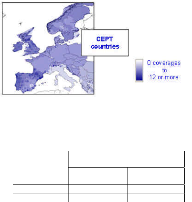
DIGITAL RADIO GUIDE TERRESTRIAL TRANSMISSION SYSTEMS - ISSUES
60
Figure 4.19: T-DAB coverages in Band III
The number of coverages can be estimated by analyzing the coverage maps taking into
consideration, when relevant, the overlapping areas between allotments or assignment
areas. The table below shows the estimated number of coverages (distinguishing
between nationwide coverage and partial coverage) for the CEPT counties.
Estimated number of coverages
T-DAB in Band III (in CEPT)
Nationwide Partial
Average 2.4 1.7
Median* 3.0 1.0
Max 5.0 9.0
*Median: 50 % of the countries have this number or more
The above table shows that in the majority of the European countries, within CEPT,
obtained 3 nationwide coverages for T-DAB and 1 additional partial coverage.
An estimation of the channel usage in Band III for T-DAB is shown in Figure 4.20 below.
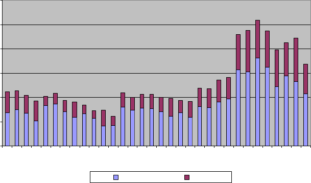
DIGITAL RADIO GUIDE TERRESTRIAL TRANSMISSION SYSTEMS - ISSUES
61
Figure 4.20: Estimation of the channel usage in Band III for T-DAB
(RPC4: suitable for mobile reception; RPC5: suitable for portable indoor reception)
0
100
200
300
400
500
600
5A
5B
5C
5D
6A
6B
6C
6D
7A
7B
7C
7D
8A
8B
8C
8D
9A
9B
9C
9D
10A
10B
10C
10D
11A
11B
11C
11D
12A
12B
12C
12D
Frequency Blocks
Number of Entries
RPC4 RPC5
Figure 4.20 shows that T-DAB mobile reception (RPC4) represents the major proportion
of the T-DAB requirements and that channels 11 and 12 are the most used for T-DAB.
The GE06 Agreement offers a great deal of flexibility for using a digital entry in the plan
for another application provided that the peak power density in any 4 kHz is respected.
Such flexibility can allow, for example, for using a DVB-T entry by 4 x T-DAB entries or by
4 x T-DMB entries and also can allow for accommodating future developments of digital
technology.
The end of the transition period for Band III has been fixed to 2015 (for some non-
European countries is 2020, see details in Figure 4.21). During that period analogue
television has to be protected. Around 25% of the T-DAB entries in the new plan have to
be coordinated with analogue television in neighbouring countries before implementation.
As a consequence, certain constraints (time constraints, power reduction, particular
antenna patterns, etc.) might be imposed to those T-DAB requirements during the
transition period. In addition, around 7% will have to coordinate with other digital
requirements and around 2.5% with other primary services (e.g., PMR - Private Mobile
Radio).
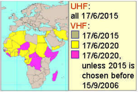
DIGITAL RADIO GUIDE TERRESTRIAL TRANSMISSION SYSTEMS - ISSUES
62
Figure 4.21: End of the transition period
In summary, the full potential of the new digital plans will not be available until the
analogue switch off.
In terms of propagation performance at L-Band using T-DAB, concern about the
efficiency of the 1.5 GHz Band has been largely removed as a result of extensive
technical evaluation and field measurements, mainly by Canada’s Communications
Research Centre (CRC). It was found that indoor reception at L-Band is comparable to
that achieved at VHF frequencies. The reason is that the shorter wavelength at L-Band
offsets the increased attenuation through walls at the lower VHF frequencies.
4.5.2 The Implications of Simulcasting
Whilst the benefits of digital broadcasting and the opportunities offered by this technology
are clear to broadcasters, there is concern about the time and cost implications of the
transition from analogue to digital. Until the coverage from digital broadcasts matches
that from existing FM and AM services, it is unrealistic to cut existing transmissions and
disfranchise listeners. It could be some years before the new digital services provide
comparable coverage and a receiver base is established. Only then can the analogue
services be closed down.
The transition from analogue to digital is helped in many countries by cooperation
between public and private broadcasters, that jointly develop the necessary infra-
structure and create attractive new programmes, and suitable regulatory arrangements.
Examples of such cooperation exist in Canada, Sweden, the UK, France, Italy, etc.
(1) HD Radio (IBOC)
IBOC transmission schemes are particularly well suited for ensuring a smooth
transition to digital services. Since they are designed for compatibility with the
existing analog signals, there is little or no disenfranchisement of listeners at the
onset of service. New receiver costs are minimised since much of the existing
circuitry can be shared by the analogue and digital portions of the receiver. And
over time, as IBOC receiver penetration reaches a “critical mass,” individual
DIGITAL RADIO GUIDE TERRESTRIAL TRANSMISSION SYSTEMS - ISSUES
63
broadcasters can be expected to have significant flexibility in determining when
and how to phase out the analogue portion of the IBOC signal all together.
In addition, the simulcasting of audio material in some IBOC systems, while done
primarily to facilitate time diversity, can also mitigate the undesired digital receiver
behaviour experienced in cases of severe signal obstructions or extreme cases of
interference. In these cases, systems without time diversity (such as Eureka 147)
exhibit what is called a "cliff effect" failure, in that the audio signal is perfect one
second, and completely gone ("muted") the next. In a simulcast IBOC system, the
existence of the "backup" analogue signal for purposes of time diversity has the
added effect of eliminating the cliff effect failure mode, since in those cases the
receiver will blend to analogue and the audio program, while degraded, will not go
away all together, and is likely to remain with the listener throughout the
impairment.
These developments are at a relatively early stage and their viability has to be
assessed, but the work carried out to date is encouraging. The audio quality
achievable with simulcasting remains to be established.
(2) DRM (Digital Radio Mondiale)
Two types of simulcast are present in the DRM design. The first is confined to a 9
or 10 kHz channel. Half the channel is used for an analogue signal capable of
envelope detection (in order that a conventional AM radio receiver can demodulate
the signal). The other half is a DRM digital signal that requires digital demodulation.
The second technique requires 18 or 20 kHz of 2 adjacent channels where one
channel contains standard AM and the other contains either a 4.5/5 or 9/10 kHz
DRM signal.
For Regions 2 and 3 the simulcast solution is potentially much simpler as the Long
and Medium Wave bands have been allocated 18/20 KHz channels. In Region 3
the 18 kHZ allocation is also protection against night time sky wave interference.
4.5.3 Coverage
The move from analogue to digital transmission raises important questions under the
heading ”coverage.”
One of the main differences between analogue and digital broadcasts is the mode of
failure when the received signal starts to fail. It happens at the edge of the service area
and at locations within the coverage footprint where the signal strength is affected by
shadowing or interference. When the signal strength reduces, analogue reception is often
described as degrading “gracefully.” By contrast, a digital signal will at some point fail
suddenly and completely. Whilst usually robust in areas of generally poor analogue
reception, the digital signal gives little indication as it approaches a point of failure.
Within a defined coverage area, the service availability from analogue and digital services
will be affected by the type of receiver (fixed, mobile or portable), by the type of
environment (urban, rural), and by the topography. It is also a function of the
transmission frequency and the system performance.
COFDM signals (such as those used in the Eureka 147, DRM and AM and FM IBOC
schemes) have characteristics which facilitate the planning of single frequency networks
DIGITAL RADIO GUIDE TERRESTRIAL TRANSMISSION SYSTEMS - ISSUES
64
(SFN’s) to a greater or lesser extent and make it easier to extend coverage. Provided
that a broadcast on the same frequency from a different transmitter, or a reflected
transmission from the main transmitter, arrive at the receive antenna within the system’s
guard interval, the reflected signal will combine in a constructive way to reinforce
reception.
One of the objectives for the Eureka 147 system was to transmit a digital signal (a
number of digitised analogue radio programmes plus data) to a mobile receiver over a
difficult transmission channel. Extensive testing has confirmed that this requirement has
been achieved successfully. The same characteristics of Eureka 147 ensure much more
rugged reception on portable receivers.
Recent development of IBOC systems in the US has also emphasised robust
performance in a multipath fading channel. Using sophisticated signal processing
techniques such as Complementary Punctured Coding, along with time and frequency
diversity, the next-generation IBOC systems are expected to exhibit fading channel
performance commensurate with that achieved in the Eureka 147 system, but this
remains to be demonstrated.
Tests and operational broadcasting have shown that DRM coverage is equivalent to the
corresponding analogue service it is replacing. Coverage, in this sense, refers to the
intended broadcast area, wherein the digital signal retains its high audio quality.
DIGITAL RADIO GUIDE SATELLITE TRANSMISSION - WORLDSPACE
65
5 Satellite Transmission
The Broad Picture
For many years, satellites in geostationary orbits (GSO’s) have been used successfully
by broadcasters for distributing programmes and services from the originating studios to
terrestrial transmitting stations. It is cost effective and reliably delivers high quality signals
to each transmitting station. This method of distribution is of particular benefit to
international broadcasters that in the past relied on SSB and DSB short-wave signals for
feeds to remote relay stations.
Today, radio broadcast services can be included in the bandwidth used for an FM
satellite television signal, or as part of a bundle of digital channels as used in Astra Digital
Radio. In all cases, satellite tuners are needed to receive these broadcasts, which are
usually transmitted in the Ku Band.
Direct radio broadcasts from geostationary satellites to fixed receivers with externally
mounted line-of-sight antennas is routine and presents no problems. It is a much more
demanding requirement to reach receivers that are mobile or portable, but the majority of
radio listeners have radio receivers of this type. Any radio transmission system, terrestrial
or satellite, which fails to deliver a satisfactory service to such receivers will probably not
find widespread acceptance.
The main difficulty in providing a satellite broadcast to an audience on the move is
occasional blockage by buildings etc. This can reduce the signal by 10 to 20 dB, which it
is impractical to compensate for with an increased link margin.
5.1 WorldSpace – ITU-R System D
WorldSpace is a commercial organisation based in Washington D.C. with world-wide
interests. It has planned for three geo-stationary satellites, named AfriStar, AsiaStar and
AmeriStar to provide global coverage. They will have L-Band payloads and each satellite
covers its designated target area with three “spot” beams. Each beam has two
transponders (one transparent and one with on-board processing). The aim is to provide
digital radio and ancillary services to audiences in the footprints of these satellites using
ITU-R Digital System D. As the names imply, the continental zones to be served by
these satellites are Africa, Asia and Central and South America. See Figure 5.1.
The primary aim of the original WorldSpace concept is to provide a simple radio service,
but as the project has developed, there is now more emphasis on mobile and multimedia
features involving data and image transmission. Trials of MPEG-4 video have been
successfully completed recently.
The WorldSpace project is innovative and has a number of points in its favour. These
include the size of the coverage areas in relation to the cost of the satellites, advanced
low bit-rate audio coding and straight forward satellite uplinking arrangements. An
enhanced service using terrestrial repeaters for reliable mobile reception is has been
successfully trialled and is being planned for introduction soon.
The approximate target regions for the transmissions from each satellite in the
WorldSpace system are shown in Figure 5.2. AfriSpace commenced operation in 1999
and AsiaSpace in 2000. AmeriSpace has not been launched. Consideration is also being
given to planning an additional satellite for providing service for Europe.
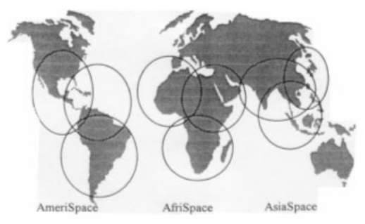
DIGITAL RADIO GUIDE SATELLITE TRANSMISSION - WORLDSPACE
66
WorldSpace has successfully launched several public benefit services including:
•General Distance Education (e.g. CLASS)
•Specialised Medical Practitioner Education
•Science Promotion
•Health Awareness
•Empowerment (Women and Girls, Business, etc.)
Satellite DSB can also be used to provide a reliable emergency and disaster warning
broadcast system. Before the Asian Tsunami in December 2004, WorldSpace had
successfully trialed a cyclone warning system for Indian Fishermen. After the Asian
Tsunami WorldSpace has been working with affected countries and aid agencies to
provide disaster relief and rehabilitation services in India and Indonesia.
Figure 5.1. WorldSpace Coverage Map (Transmission Footprints)
Depending on the audio quality required for each service, each transponder of each
beam on one of the satellites is capable of carrying up to 96 x 16 kbps services. Audio
coding developed by the Fraunhofer Institute (FHG) for the project is based on the MPEG
Layer 3 algorithm with customisation to suit the WorldSpace project. The coding rate for
each service is available in simple multiples of a basic 16 kbps channel, up to a
maximum of 128 kbps. Subjectively, the system offers audio quality standards :
Better than AM 16 kbps
Mono FM 32 kbps
Better than ‘near stereo’ CD 64 kbps
Stereo CD 128 kbps
Data services are provided at up to 128 kbps per channel, using either a shared or
dedicated channel.
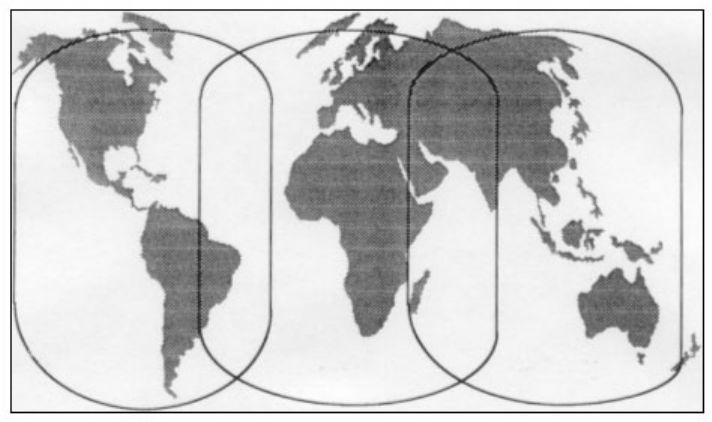
DIGITAL RADIO GUIDE SATELLITE TRANSMISSION - WORLDSPACE
67
Broadcasters using the service are able to uplink their programmes from either
centralised hubs or via individual feeder links located in any of the uplink footprints of the
3 satellites. Whilst this ease of access for broadcasters is a plus feature, the low power
single channel uplink with its large footprint could be vulnerable to jamming. There have
not been any occurrences of jamming to either satellite in more than four years of
continuous operation, and procedures are in place to handle such attempts.
Figure 5.2. WorldSpace Up-link Coverage
AmeriSpace AfriSpace AsiaSpace
Broadcasters using the WorldSpace system have the choice of using a low power uplink
local to the studio (PFLS), or routing their service(s) to a remote, high power uplink
(TFLS) site. This arrangement is possible by the use of Frequency Division Multiplex
Access (FDMA) for the uplink.
When received at the satellite, the signals from a PFLS are ”assembled” by the on-board
processors to form a broadcast multiplex. The arrangement will allow each of the three
spot beams to downlink its own multiplex on the processed transponder. In short, the on-
board processing simplifies the uplinking procedures.
The downlink for each beam uses Time Division Multiplex Access (TDMA) and the
baseband processing on-board the satellite carries out the FDM to TDM conversion.
For its transmission system, WorldSpace uses a system it has developed itself (early in
1998, WorldSpace made details of the system available to the ITU-R and the system is
now designated ITU-R System Ds). The WorldSpace decision to use time division
multiplexing (TDM) provides a greater link margin (the extent to which the clear sky
carrier to noise ratio exceeds the threshold for reception level) than would be available
with a COFDM system such as Eureka 147 (T-DAB). A greater link margin can be used
to serve a larger coverage area, but cannot overcome the problem of blockage, which is
a fundamental problem for all satellite systems.
DIGITAL RADIO GUIDE SATELLITE TRANSMISSION - WORLDSPACE
68
Subsequently WorldSpace developed a hybrid satellite and terrestrial repeater system
designated as ITU-R System Dh to provide reliable reception in vehicles. This system
has other enhancements including time diversity. This system has also been utilised by
XM Satellite Radio to provide DARS services in the US (refer to Section 5.2).
5.1.1 Receiver Systems
Receivers for the WorldSpace system are described on the Worldspace website at:
www.worldspace.com/receivers/bundle.html. Agreements reached in June 1996 with
SGS-Thomson and ITT Intermetall to produce a very large number of silicon chipsets
marked an important milestone in the development of receivers for this project. By
implication, the RF specification for the system had at that stage been completed.
An announcement about the manufacturers of the WorldSpace Starman receivers was
made in June 1997. The named manufacturers were:
•Hitachi
•JVC
•Panasonic
•Sanyo
More recently WorldSpace has licensed a number of manufacturers in India, China,
Korea, Indonesia and Thailand to manufacture low-cost receivers for domestic and export
markets. New generation receivers for the enhanced hybrid satellite/terrestrial service are
currently being developed.
DIGITAL RADIO GUIDE SATELLITE TRANSMISSION - SIRIUS / XM
69
5.2 SIRIUS Satellite Radio / XM Satellite Radio
These two US-based organisations have implemented and are operating satellite radio
systems providing a variety of mobile/fixed services throughout the 48 contiguous states,
in Canada and offshore. Both intend to offer services within Mexico as soon as
regulatory approvals can be obtained.
The services are currently audio channels of music or voice. They typically offer 100
audio channels, 60 of which are various genres of music and 40 of which are voice (talk,
news, sports, etc.). Demonstrations have been made of possible future offerings of data
and video.
The services are offered to subscribers at rates which vary as a function of subscription
length; the highest being a monthly rate of approximately $13 US, and $499 US for the
life of the radio being the lowest assuming a five year lifetime. However, discounts and
promotions (some of which include the purchase of the radio) provide great variability.
The services are provided to mobile vehicles (private automobiles, trucks, boats and
airplanes) and to homes and businesses. The number of subscribers at the end of 2006
is over 14 million with the preponderance being in motor vehicles. There are two types of
receivers for this market. The first type is called aftermarket where subscribers wish to
add a satellite radio capability to their existing car. This is accomplished by purchasing
an auxiliary receiver with a satellite antenna at a local retailer, many of which also install
and activate the equipment. Connection to the car’s audio system is either direct,
through the FM radio or through the cassette player depending on the existing radio’s
design and user preference. The second type is called OEM where subscribers buy a
new car with the satellite receiver installed, either at the factory or dealer, and the car is
delivered with the satellite radio capability activated. Costs of such receivers vary, the
current range being approximately $150-$300 US without promotions.
Various models of the aftermarket receiver exist such as plug-and-play, home,
transportable (e.g., boombox), boat, etc. One of the more popular is the plug-and-play
receiver, which is sold with a dock for home installation and a dock for automobile
installation. The subscriber can simply move the receiver from one location to another,
thus avoiding the need to purchase a second one. The future trend is believed to be
towards OEM radios as well as to reduce costs of receivers, primarily due to improved
ASIC chipsets (which are the heart of the receiver) and consequent increased
manufacturing volume.
The Sirius and XM services are similar except for the music channels where Sirius has
no commercial advertising. The systems are different however. Both systems use the
12.5 MHz bandwidth assigned (Sirius radio frequency allocation is 2320.0-2332.5 MHz
and XM is 2332.5-2345.0 MHz) by employing approximately the top and bottom 4 MHz
for satellite transmission with TDM/QPSK modulation and the center 4 MHz for terrestrial
repeaters. These terrestrial repeaters take the satellite signal and rebroadcast it in the
urban cores of large cities with COFDM/QPSK modulation to overcome service outages
from blockage. Sirius transmits all its channels in one contiguous block approximately 4
MHz wide while XM divides its channels in half, transmitting them in two blocks each
approximately 2 MHz wide.
The Sirius and XM orbital designs are also different. Sirius employs a constellation of 3
satellites in an inclined, elliptical geosynchronous orbit while XM employs 2 satellites in
geostationary orbit.
Both systems use satellite space, time (4 seconds) and frequency diversity to achieve
very high availability of service (e.g., above 99%). Sirius chose its orbit to maximize
subscriber elevation angle to the satellites in the northern third of the United States which
DIGITAL RADIO GUIDE SATELLITE TRANSMISSION - SIRIUS / XM
70
reduces the need for terrestrial repeaters and lowers the probability of outages from
blockage and foliage attenuation. Currently, Sirius employs approximately 100 repeater
sites and XM approximately 800.
5.2.1 Sirius Overview
The first Sirius spacecraft was launched on July 1, 2000. Exactly five months later, on
December 1, the third spacecraft was launched, completing the three satellite S DARS
(Satellite Digital Audio Radio Service) constellation. The three spacecraft are deployed in
inclined, elliptical, geosynchronous orbits, which allow seamless broadcast coverage to
mobile users in the contiguous United States. Terrestrial broadcast repeaters provide
service in urban cores. The system is in operation, providing the first ever S-DARS
service.
The constellation design results in satellite ground tracks over North America with two
satellites always above the equator. High elevation look angles from the mobile ground
terminals to the satellites minimize performance degradation due to blockage, foliage
attenuation and multipath.
The spacecraft were built by Space Systems/Loral using the 1300 bus modified for
operation in high inclination orbits. Each spacecraft was launched using a dedicated
Russian Proton booster. The satellite payload is a bent pipe repeater using 7.1 GHz for
the uplink and 2.3 GHz for the broadcast transmission. The repeater high power
amplification stage consists of 32 Traveling Wave Tube Amplifiers phase combined to
yield a total RF output power of nearly 4 kW at saturated operation. The satellite
antennas are mechanically steered to maintain the transmit beam centered on CONUS
(Contiguous United States) and the receive beam centered on the uplink earth station
located in Vernon Valley, New Jersey.
The satellite payload design and performance are described. The principal spacecraft
bus systems are described with emphasis on improvements made for operation in the
inclined, elliptical geosynchronous orbits.
The two active satellites transmit the same signal at different frequencies with a 4-second
delay between them, which is inserted at the uplink earth stations. In the urban core of
large cities where satellite blockage can be very high, terrestrial transmitters rebroadcast
the satellite signal. The satellites’ different orbital positions, transmission frequencies and
signal delay provide the diversity while the receivers’ equalizer and maximal ratio
combiner (e.g., sums the two satellite and terrestrial repeater signals) provide the other
listed techniques. Moreover, the achievement of high elevation angle is an extremely
important attribute, and its achievement required the adoption of a unique orbital
configuration.
Originally Sirius Satellite Radio had planned for geostationary satellites at 80° and 110°
West longitude. The resulting low elevation angles to mobile users in the northern third
of CONUS would cause service outages whose number and duration result in an
unsatisfactory quality of service irrespective of the diversity employed and the satellite
Effective Isotropic Radiated Power (EIRP) level. Satisfactory service might be achieved
by deploying an enormous number of terrestrial repeaters but this was judged impractical
given the economic and regulatory issues involved. Consequently, an orbital
constellation was designed by Sirius Satellite Radio and implemented by Space
Systems/Loral (SS/L) that provides high elevation angles over this critical area.
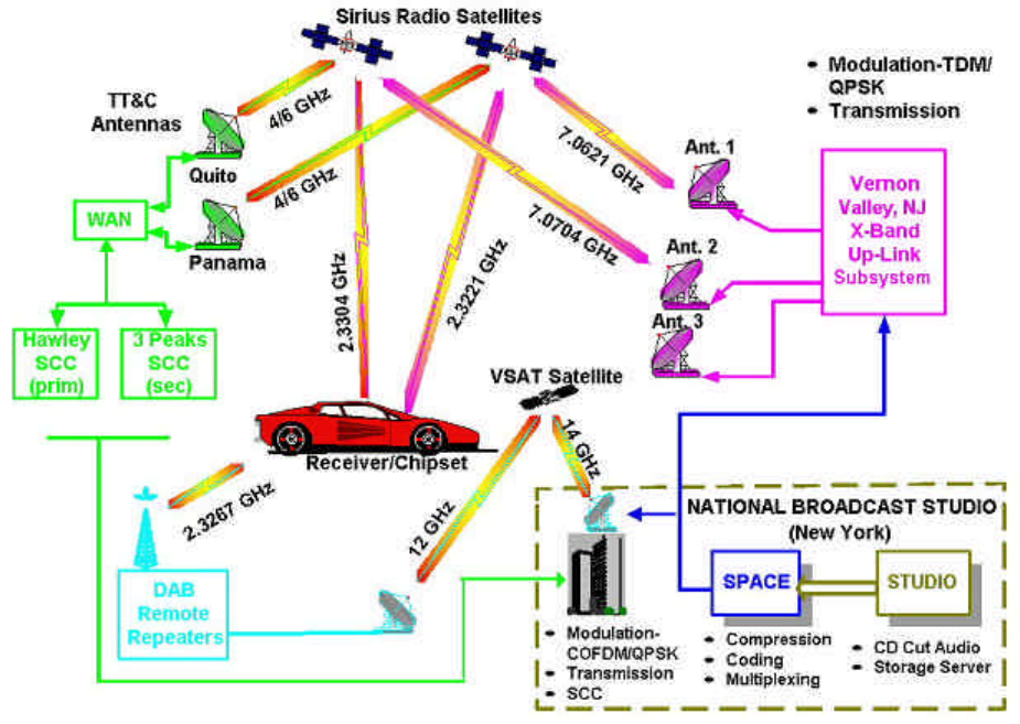
DIGITAL RADIO GUIDE SATELLITE TRANSMISSION - SIRIUS / XM
71
Figure 5.3. Sirius SDARS Delivery System
Sirius SDARS Delivery System
The Sirius constellation consists of three satellites in inclined, elliptical geosynchronous
orbits whose planes are 120° apart, as shown following. The satellite orbital elements
are given in the accompanying table, and the satellites’ ground tracks are also shown.
The orbital configuration was designed so that each satellite spends 16 hours north of the
equator, during which time it is used for transmission, and 8 hours south of the equator
when it is inactive.
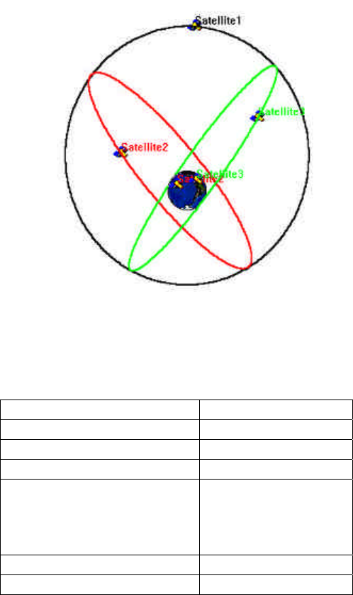
DIGITAL RADIO GUIDE SATELLITE TRANSMISSION - SIRIUS / XM
72
Figure 5.4. Sirius Constellation
Each satellite follows the other around the ground track in following picture with 8-hour
separation. The perigee in the southern hemisphere is 24,500 km, which is above the
Van Allen belt, and the apogee in the northern hemisphere is 47,100 km.
Semi-major axis 42,164 km
Eccentricity 0.2684°
Inclination 63.4°
Argument of Perigee 270°
RAAN*
•FM-1
•FM-2
•FM-3
285°
165°
45°
Apogee Altitude 47,102 km
Perigee Altitude 24,469 km
*Right Ascension of Ascending Node
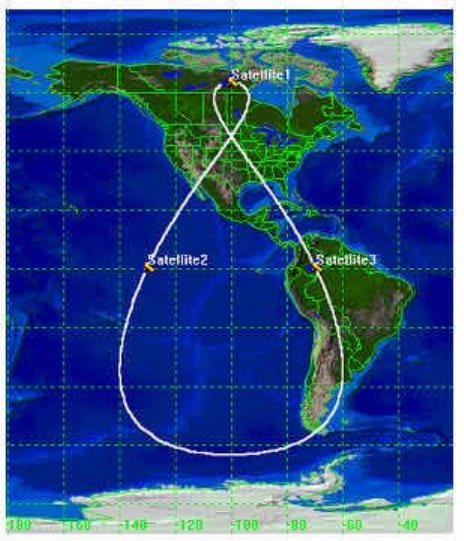
DIGITAL RADIO GUIDE SATELLITE TRANSMISSION - SIRIUS / XM
73
Figure 5.5. Sirius Ground Track
The decision to use inclined, elliptical orbits rather than geostationary orbits for Sirius was
made approximately one year into the design and manufacturing phase of the project. At
the same time, modifications were made to the payload requirements, affecting
spacecraft configuration and support subsystems. While the majority of the satellite
hardware remained unchanged, a number of modifications were required. Several
design trades and decisions were influenced by the existing state of design and
development. The program was carefully replanned to accommodate late arrival of new
or modified hardware and software, while maintaining the integrity of the overall system
testing. The highest priority was given to quality and reliability of the end product. No
“shortcuts” were taken during the development or qualification of new hardware or
software. The overall success of the program demonstrated the ability to respond quickly
to a change in the implementation plan. The following table summarizes the
modifications made to the 1300 design for the Sirius application.

DIGITAL RADIO GUIDE SATELLITE TRANSMISSION - SIRIUS / XM
74
Changes Made For Sirius Inclined Elliptical Orbits
Parameter Geostationary Inclined Elliptical
Dry Mass 1300 kg 1575 kg
RF power (operating) 2.5 kW 4 kW
DC power – EOL
Solar Array
Battery
7.5 kW
7.5 kW
8.5 kW
8.8 kW
Control System 3-wheel mom bias 4-wheel mom bias
On-board orbit
propagator
Control Modes Orbit Normal Orbit Normal
Yaw Steering
TX Antenna Fixed Gregorian
Gain 27.8 dBi;
Cross-pol 24 dB
Gregorian; two axis
steering 360º rotating
shaped subreflector
Gain 27.2 dBi; Cross-
pol 28 dB
RX Antenna Fixed offset fed Offset fed; two axis
steering
Solar array 2x4 panel HES 2x5 panel HES
Battery 2x32 cell - 149 AH 2x34 cell - 178 AH
TT&C X, C and S bands
CONUS ground station
Limited motion antennas
C and S bands
2 near equatorial
ground stations Full
motion antennas
Launch Vehicle Ariane Proton
The launch of the Sirius Satellite Radio constellation marks the first use of satellites for
Digital Audio Radio Service broadcasting in the United States. The three high power
direct broadcast satellites will provide service for millions of subscribers. The Sirius Radio
system is the world’s first satellite broadcast system using non-geostationary orbits.
The use of inclined elliptical orbits coupled with multiple modes of transmission diversity
provides notable advantages for broadcast service to the mobile market. Pioneering
technology was developed and implemented by Sirius Satellite Radio and Space
Systems/Loral in order to accomplish this unique achievement.
5.2.2 Deployment Status
Current population and transmission status of Sirius and XM satellite radio services is
shown in the following chart.
Continental US
Coverage
Satellites Ground
Repeaters
Sirius Satellite Radio 100% 3 in HEO ~100
XM Satellite Radio 100% 2 in GSO ~800
DIGITAL RADIO GUIDE SATELLITE TRANSMISSION - MOBILE BC / TU MEDIA
75
5.3 Mobile Broadcasting Corp. and TU Media Corp. – ITU-R System E
Mobile Broadcasting Corporation is a commercial organisation based in Tokyo, Japan
and TU Media Corporation is a commercial organization based in Seoul, Korea. Although
they have one geostationary satellite in common, each of them can use its own
transponders and is independently providing high quality digital audio, medium quality
digital video and multimedia data services to vehicular, portable and fixed receivers using
the satellite and a number of terrestrial repeaters. The same frequency band, 2630 -
2655 MHz, is used by sharing polarization. The service area of Mobile Broadcasting Corp.
is Japan and the service area of TU Media Corp. is Korea. Broadcasting signal can be
received by receivers with small antennas. To generate enough EIRP for mobile
reception, the satellite is equipped with a large transmitting antenna and high power
amplifiers. After the launch of the satellite in March 2004, the commercial service in
Japan was started in October 2004, currently including 30 audio channels, 8 video
channels and about 60 items of multimedia data services. The commercial service in
Korea will be started in May 2005, including 22 audio channels and 12 video channels.
The major issue related to signal propagation in BSS (sound) is signal loss due to
blockages on the signal path from the satellite to the receiver. Two techniques are used
to overcome this issue. One of them is bit-wise interleaving, which is used to overcome
the instantaneous signal loss caused by blockages, such as bridges over highways, in
vehicular reception environment. Invalid data generated due to the signal loss are
distributed over several seconds through the deinterleaver and corrected through the
decoder of forward error correction code in the receiver. The period of the signal loss
which can be recovered by this technique is approximately a second. The other method
is introducing terrestrial repeaters. The terrestrial repeaters retransmit the satellite signal
and are expected to cover the area where signal loss occurs due to blockages, for
example, buildings and large constructions. In the circumstances, where terrestrial
repeaters exist, multipath fading appears at the receiver because more than two
broadcasting signals are received at the same time. The CDM (Code Division
Multiplexing) and RAKE combining technique is adopted, so that the same frequency
band is used for the satellite and the terrestrial repeaters.
The system was approved by ITU in July 2000 as ”Digital System E’ in Recommendation
ITU-R BO.1130, System description and selection for digital satellite broadcasting to
portable, vehicular and fixed receivers in the bands allocated to BSS (sound) in the
frequency range 1400 – 2700 MHz.”
5.3.1 Receiver Systems
The services are provided to persons, to mobile vehicles (automobiles, trucks, boats and
airplanes) and to homes. There are several types of receivers for this market at the
moment; palmtop receiver, PC card receiver, plug-and-play receiver and mobile phone
type receiver. Palmtop receiver is a dedicated receiver with 3.5-inch LCD, which is small
and light enough to be carried to any place. PC card receiver is used with a notebook
computer and you can enjoy video services on the display and audio services through the
speakers while you are using the computer. Plug-and-play receiver is used with cradles,
which are installed in car and at home, so that you can use the receiver not only in car
but also at home without buying extra receiver. Mobile phone type receiver is embedded
in a mobile phone and you can receive video or audio services at anyplace without
bringing additional equipment, though the display is rather smaller than that of dedicated
palmtop receiver.
DIGITAL RADIO GUIDE INTERNET RADIO
76
6 Internet Radio (IR)
6.1 Introduction
Traditionally, audio programmes have been available via dedicated terrestrial networks
broadcasting to radio receivers. Typically, they have operated on AM and FM platforms,
with the more recent addition of digital radio-frequency spectrum, including DAB, DRM
and IBOC. This paradigm is about to change.
Radio programmes are increasingly available not only from the terrestrial networks, but
also from a large variety of satellite, cable and, indeed, telecommunications networks
(e.g., fixed telephone lines, wireless broadband connections and mobile phones). Very
often, radio is added to television broadcasts. Radio receivers are no longer only
dedicated hi-fi tuners or portable radios with whip aerials, but are now assuming the
shape of multiple multimedia-enabled computer devices (desktop, portable, PDA, Internet
radios).
This sea of changes in radio technologies impact dramatically on the radio medium itself -
the way it is produced, delivered, consumed and paid-for. Radio has become more than
just audio - it can now contain associated metadata, synchronized slideshows and even
short video clips. Radio is no longer just a "linear" flow emanating from an emission mast
- audio files are now available on-demand or stored locally for time-shifted playout. It is
the convenience of the user, rather than the broadcaster-imposed schedule, which
matters now.
Internet Radio (IR) is a relatively recent phenomenon. Nevertheless, during the past ten
years Internet has become a very important distribution mechanism for audio and video
streams and files. Audience statistics show that IR is increasingly popular, especially
among young people and users in offices.
This paper introduces the concept of IR and provides some technical background. It
gives some examples of actual IR services now in place in different countries. Finally, it
provides some guidance on how traditional radio broadcasters need to adapt and adjust
in order to be capable of meeting the requirements of the rapidly changing multimedia
environment.
6.2 Bringing Radio to the Internet
Internet penetration worldwide is very close to the one billion users mark. Almost 70% of
the American population have access to the Internet from home, and one-third access
the Internet at work. Canada, South Korea, Japan and Germany follow closely at 60-
70%. The use of the Internet is growing at a tremendous rate. Recently published
statistics suggest that, on average, 31 connections are made per month, and more than
26 hours are spent browsing the Internet each month to visit 66 sites and view 1268
pages. Eighty-seven per cent of uses send e-mail massages, 60 per cent use instant
messaging services and 55 per cent download files. Twenty-two per cent of users
worldwide have already tried video on the Internet.
The American Media Research company, Arbitron/Edison (www.arbitron.com), released,
in 2005, results of a major study on Internet and Multimedia in the US. This study
suggests that an estimated 55 million consumers use Internet radio and Internet video
services each month.
DIGITAL RADIO GUIDE INTERNET RADIO
77
The study identified the following reasons why people listen to Internet radio, as opposed
to off-air radio:
To listen to audio not available elsewhere 17%
To control/choose the music played 15%
Fewer commercials 14%
Greater variety of music 13%
Clearer signal than over-the-air radio 8%
Less DJ chatter 8%
Because it is "new" 7%
Internet listening appears to be concentrated among well-known Internet radio brands
such as America Online's AOL® Radio Network; Yahoo!® Music, Microsoft’s MSN Radio,
WindowsMedia.com and Live365. Every week, these stations reach an average of 4.8
million listeners aged 12 and older during the hours of 06.00 – 00.00. Listeners to these
five major Internet radio brands account for roughly one out of four of the 20 million
weekly Internet radio listeners in the US.
6.3 Internet Radio peculiarities
Radio over Internet differs from other delivery media in three ways:
•It is a relatively new way to experience radio via a computer device. The consumer
uses a new interface (screen, keyboard, mouse) and is able to search and select
different content according to the station name, country of origin, genre or style, as
well as viewing the currently played programme ("Now Playing"). The station's
frequency (as in FM or AM) or multiplex (as often in DAB) is irrelevant. The users can
shortlist their preferences by compiling personalized favourites lists. In addition, it is
possible to generate a virtual station schedule according to one's preferences. An
"on-demand radio" is also offered by many traditional broadcasters on their websites;
this allows the user to click and play the archived programme items which were
broadcast via conventional terrestrial channels during the previous seven days or so.
•IR widens the choice of service providers. These can be traditional radio
broadcasters, new (Internet-only) stations, portals or independent users.
•Radio content on the web can differ from radio broadcasting as it has evolved over
the last century. Whereas on terrestrial networks the choice of stations is relatively
limited, there are thousands of IR stations. It is often possible to choose from a list of
most popular stations or to find a station which is playing a particular song from a
"Top 50" list. Since computers can use hard disc memory, it is possible to time shift
play out.
One of the fundamental differences between IR and conventional radio is the absence of
barriers to public transmission. Consequently, even a small, local station can potentially
become a global player, or at least an international station.

DIGITAL RADIO GUIDE INTERNET RADIO
78
6.4 Internet Radio as a complement to established radio services
Since 1995, most traditional broadcasters have set up websites in order to provide
complementary information for their listeners and viewers. The websites can provide a
variety of textual and pictorial on-line services, as well as on-demand audio or
audio/video clips associated with news events and live (continuous) reproduction of
existing radio and television programmes.
For conventional broadcasters IR could usefully complement existing on-air broadcasts.
IR works best as a narrow-cast medium targeting a small number of concurrent users.
Should this number increase to more than a thousand (or several thousands), Internet
streaming servers are generally not capable of providing the streams economically. In
other words, IR is only really useful if it is kept relatively small. For example, it is probably
not very sensible to use Internet for big one-off events such as Live 8 on 2 July 2005,13
as satellite or terrestrial networks can reach many more people.
IR is best suited to niche content, such as education, specialist music, and programmes
aimed at ethnic minorities, which may be of interest to a relatively small number of people.
Often it is considered too extravagant to use scarce spectrum for such programmes.
IR can offer a solution for communities scattered across the world. For example, there
may not be enough fans of gypsy music in a given part of the world to justify a local
broadcast station, but if we add listeners around the world who are interested in this kind
of entertainment the potential audience will look a lot healthier.
While it is easy to introduce a new IR stream for niche radios, it is more difficult, if not
impossible, to find spectrum for FM station, which is already very congested in some
large agglomerations. One example is SR International's Immigrant Languages Service,
which is primarily intended for immigrants within Sweden, but also reaches audiences
abroad through its webcasts.
The scalability of IR is a major issue. When audiences are relatively small (e.g. several
hundreds concurrent listeners), bandwidth – and thus cost – is reasonable. However,
when audiences increase, operational cost may escalate. In a way, a station may
become a victim of its own success. A peer-to-peer (P2P) approach may help reduce
distribution cost. Multicast is also an option, but it requires multicast-enabled routers
which may not be readily available everywhere. Also, multicast excludes on-demand
delivery.
IR is inherently interactive. IR websites are places for listeners to interact not only with
the station, but also with each other. These interactions are usually achieved through text
messages, e-mail forums or chat rooms, as well as in a growing number of cases, audio
and video messages. Indeed, listeners may become active contributors to the website
audio-visual content. For example, programme files could be mailed in from around the
world direct from artists or music groups. As an example of interactivity and audience
active participation, NRK - and other European broadcasters - have organised country-
wide contests of amateur pop groups, allowing users to vote and select the most popular
group.
IR websites have a unique possibility to offer both live and on-demand audio
programmes. Many radio stations have created on-demand online archives enabling their
listeners to hear programme items that were originally broadcast on-air, for example, up
13 Musicians and artists from around the world joined together to influence the struggle to end global poverty. There were
pop music concerts from 9 different places around the globe on the same day with several hundreds million watching
on TV and listening to the radio. Among others, WorldSpace UPOP Music Channel 29 transmitted the concerts in
real time (live).
DIGITAL RADIO GUIDE INTERNET RADIO
79
to seven days before. One example is the BBC Radio Player. This on-demand service
allows users to time-shift broadcasts and frees them from the constraint of adhering to
station schedules. On-demand transfers control to the listeners: they can create their own
schedule of programmes.
Web radio has the advantage of allowing broadcasters to measure audience directly (see
Section 6.9). Broadcasters using a Windows Media Server, or other streaming media,
will have detailed reports of the streams played, while those using web servers can
estimate audience sizes by viewing the traffic statistics found in the web server log file,
an automatically-generated list of all the files served.
IR adds a global audience which may be important for ethnic minorities scattered around
the world. While terrestrial radio is generally limited to a certain geographical territory,
IR's audience is effectively global and is redefined according to shared interest. IR radio
introduces a concept of a multitude of niche audiences spread globally and not
necessarily limited to one geographical region or country.
6.5 Internet-only stations: IR Portals and Music Portals
There are a number of web radio sites that offer customizable programming using their
own players or ones already loaded onto your PC. Most sites feature dozens of different
musical genres from baroque to zydeco and some allow you to tune in to live broadcasts
from around the globe.
There are also Internet portals which help the user find a suitable IR station. Portals such
as radio-locator.com allow users to search for stations according to genre (or format),
name, location (city, state or country), frequency (if the station is already on the air) or
even owner. Often several thousand stations are available on such portals. Some radio
portals are listed in Section 6.12.
Lists of FM and AM radio stations can be made available over the Internet to mobile
devices such as a Palm OS or Windows CE handheld computer using suitable software.
6.6 Streaming technology for radio services
With recent technological improvements such as rapid adoption of high-speed
connectivity and ever increasing computer processing and storage power, streaming over
the Internet (sometimes called webcasting) has become a mainstream media delivery
platform. Universal standards for audio and video delivery have emerged to gain
widespread adoption in the marketplace. In addition, user experience of watching video
and listening to audio online has improved dramatically. Issues such as incompatible
formats and versions or browser incompatibility are now less critical.
There are different standards for encoding and delivering audio files and streams online.
Following the pioneering developments of RealNetworks, Windows Media and QuickTime,
it now seems that MPEG-4 will dominate. MPEG-4 represents a major step forward in
audio/video coding, as it supports new types of media objects, such as 3D and synthetic
objects. It supports interactivity at the client and server side. It is highly scalable and
covers video resolutions from a thumbnail size suited to mobile applications to HDTV for
home cinema, and from monophonic audio at 20 kbps to multichannel audio in the MBps
range.

DIGITAL RADIO GUIDE INTERNET RADIO
80
The streaming system architecture comprises four elements: capture and encoding,
serving, distribution and delivery and media player.
Capture and encoding takes the source audio from the microphone and exports it into a
compressed (encoded) computer file. These files are stored on a content server which
controls the real-time delivery of the stream. The distribution channel (usually the
Internet) connects the server to the player. The media player renders the media on the
PC or another device (hand-held wireless devices, games consoles, interactive TV, etc).
As Internet is overlaid on telecommunications infrastructure, IR is now widely available
via a variety of two-way communication networks, both wired and wireless. narrow-band
(dial-up) at home and broadband connections in offices, via WLAN hot spots in airports,
congress centres and other public places. The number of listening hours is staggering.
Broadband access is obviously a big plus and some of the streams are so good you can
enjoy them over your home stereo system.
IR services can be delivered in a variety of configurations ranging from direct server-
client to podcasting.
(1) Server-client
Unicasting is a classical approach to radio streaming. Requests from clients (users)
to receive a stream are managed by a server or a cluster of servers. In case of
clustering, load balancing is used to improve reliability of the stream delivery,
especially if one of the servers breaks down. The server cluster feeds a common
Internet line used to transmit the streams to the clients. The total bandwidth
provided by such a server farm is proportional to the number of clients and the
bitrate of streams. This means that doubling the number of clients or bitrate will
double the system capacity and cost.
Unicasting also has a "scaling" problem. Since all the streams are transmitted to
the Internet from one source, a server quickly reaches its upper capacity limit,
resulting in a "server busy" message.
(2) Distribution networks
The Content Delivery Network (CDN) consists of a large number (typically several
thousand) of "edge"14 servers situated around the world. Each server uses the
same home page and is uploaded with the same content. The user gets content
from the nearest server, so that the access delay is minimal. The CDN approach
distributes the load among the geographically separated servers and increases the
possible number of concurrent requests and streams that may be handled. The
CDNs can potentially cater to several thousand simultaneous streams but are very
costly. For example, Akamai's globally distributed edge computing platform
comprises more than 15,000 servers in more than 1,100 networks in 70 countries.
14 The word "edge" is used here to mean "close to the user".
DIGITAL RADIO GUIDE INTERNET RADIO
81
(3) WiMAX
WiMAX is a new IP-based communications technology based on the IEEE 802.16-
2004 standard, which will provide broadband wireless access to portable devices
like laptops, personal digital assistants (PDAs) and smartphones. WiMAX will
complement fixed DSL and WiFi networks by providing mobility and portability. It
will offer seamless hand-over between WiMAX, WiFi and mobile 2G/3G networks.
It will bring new dimension (mobility) to broadband TV and Radio. For more
information, see www.wimaxforum.org.
(4) Multicasting
Multicasting is a solution to serve a single stream to multiple users. The multicast-
enabled network routers clone (replicate) the Internet datagrams (packets) for each
user requesting the stream. Therefore the same content is conveyed to a group of
users. Multicasting cannot use automatic rate changing and is not suitable for on-
demand services. If multicasting is to be used for several sites at the same time,
then Virtual Private Networks (VPN) should be used to bring the stream from the
originator to these sites, and then multicast locally.
(5) P2P networks
Peer-to-peer (P2P) networks refer to computers that communicate directly with
other computers without passing through intermediaries. It enables users to pool
resources, such as processing power, storage capacity and bandwidth to
overcome the problems of congested Internet links and server crashes. Internet
radio broadcasters are beginning to use P2P systems to distribute their content in
what looks like a win-win situation, with consumers obtaining a more reliable
service and broadcasters benefiting from drastically reduced bandwidth fees.
Since P2P networks have the potential to create distribution channels which are
more efficient than traditional broadcasting, some analysts have gone as far as to
suggest that this will inevitably bring about a massive paradigm shift. In a P2P
scenario, there would be no need for the "middleman" - consumers would
download content directly from programme producers. This would lead to a
massively reduced role for traditional broadcasters who would be relegated to
providing only live sport and breaking news.
P2P systems use several distinct techniques to distribute files more efficiently. One
of the most widespread is "swarming," which was pioneered by BitTorrent. In this
technique, peers share portions of data: files are broken down into small pieces
and then distributed randomly between peers who exchange the pieces in order to
complete a sort of jigsaw puzzle.
The Danish-based company, Octoshape, which has worked closely with Danish
Radio, claims that its GridCasting solution saves 97% of bandwidth compared to
the traditional server farm solution. As with other P2P technologies, the more
people who download files, the faster they download. Other potential benefits
include higher quality bitrates, instant play, no buffering and fewer interruptions.
In Britain, the BBC is working with Kontiki P2P technology to provide a new online
service that will allow viewers to download radio and TV programme from the
previous seven days free of charge.

DIGITAL RADIO GUIDE INTERNET RADIO
82
(6) Podcasting
Podcasting is a way to 'subscribe' to radio programmes and have them delivered to
your personal computer. Podcasting stands for Personal On-Demand
(narrow)casting. It combines blogging with audio files that can be played on your
PC or MP3 player. It involves a “push” of specially encoded multimedia content to
subscribed PCs via RSS 2.0 protocol. Podcasting allows the listener to choose not
only to what to listen to, but also when and where. Users can return feedback and
comments. It is not limited to radio and music (typically encoded in MP3) but can
include video, films, games, etc. Is not limited to broadcasters, virtually anybody
who has content can become a podcaster.
Subscribers to Radio podcasts can automatically receive the latest edition of the
programme in the form of a file. This file can then be easily transferred to a
portable MP3 player. To do this, users need an Internet connection and a piece of
podcast software which is usually available free of charge. This software can check
the radio station for content updates and automatically download them to the player
as soon as they are available. As a general rule, programme files can be made
available shortly after broadcast, but in some cases this may be several hours later.
There is a multitude of podcasting software available from
www.podcastingnews.com. This software varies from one computer platform to
another (Windows, Mackintosh, Linux, etc). The same website also provides
software for publishing podcasts.
6.7 Internet Radio terminals and playback devices
Internet radio terminals are user devices which can reproduce streaming content. In the
beginning, streams could be played by a software application on the PC. Now we are
seeing media players in mobile devices and in home entertainment products such as the
set-top box. Today, a PC user may have three or more players installed to provide
support for different codecs available in the market. Thankfully, PC makers have made it
easy with pre-loaded music players, from Apple's ITunes and QuickTime, to Real Player
and Windows Media Player.
Players can be used in three different ways: as a content portal, a stand-alone player, or
a plug-in to a web browser. In the latter case, the streaming content may become an
integral part of a synchronised rich media experience, combining text, graphics, audio
and video (using SMIL15).
Audio-only players are still very popular, as there is huge demand from music lovers to
download tracks over the Internet. They serve as a jukebox to organise music libraries
and set up playlists. They can also rip CDs, store MP3 files on the hard drive and
download to portable music players such as iPod. Examples include WinAmp from
NullSoft, and iTunes from Apple.
Today, about 95% of all media players installed on the desktops worldwide, are
Microsoft's Windows Media. RealPlayer and QuickTime follow closely by 86% and 82%,
respectively. Flash players are becoming increasingly popular for multimedia, whereas
MP3 are mostly used for downloadable audio files.
15 Synchronised Multimedia Integration Language
DIGITAL RADIO GUIDE INTERNET RADIO
83
An interesting example of a PC audio player is the BBC Radio Player which is a PC
application that allows Internet users to download BBC radio programmes via a
programme guide for up to 7 days after broadcast. BBC is now in the process of trialling
an Integrated Media Player (iMP) which will allow for both radio and television
programme downloads but, due to copyright restrictions, only to the UK territory. For the
users' benefit, the programme guide is available a week in advance and a week behind.
Users are able to download programmes as soon as they have been broadcast on TV
and Radio and can watch them as many times as they like during seven days. iMP also
allows users to subscribe to a series which automatically downloads each programme
immediately after being broadcast.
Music download is now a feature of 3G mobile phones. Motorola and Apple joined forces
to market a device combining iPod with mobile phones. For the moment, downloading
songs still has to be carried out via the Internet and the user's PC, although in the near
future the mobile phone could do it via 3G networks direct.
It is also worth mentioning the possibility to attach a small FM transmitter to a portable
iPod player for listening on car radios. This is important, as radio listening in the car may
be affected. Some people may choose to listen to their personal collection of pre-
recorded files on iPods, rather than listening to local FM or AM stations. Just as
commuters are catching up to the idea of satellite radio for their cars, a new wireless
approach called "Roadcasting" will allow you to tune your radio to music playlists coming
from other cars on the motorway.
A special category of IR terminal devices are disguised computers which look like old
radios but can connect to Internet radio stations. An early example of this approach is
Kerbango from 3Com (no longer available on the market). Newer Internet radio receivers
include products from Reciva, Acoustic Energy, Noxon, Slimdevices, SoundBridge,
Solutions and others. For example, Acoustic Energy uses a wireless broadband
connection and supports Real Audio, Windows Media and MP3. Radio stations' URLs are
store on a central database which can be easily updated on request to accommodate any
other radio stations. Currently, more than 10,000 stations from virtually any country
worldwide and of more than sixty different genres are available. Typically, the prices of
Internet radios range between $100 and $200 US.
Another consumer electronics device which allows consumers to listen to Internet radio
and Internet music is Streamium from Philips. The concept here is different because you
need a separate PC and a broadband Internet connection. The PC and Streamium can
be located in two different rooms (which is convenient because of the fan noise of the
PC) and are connected wirelessly using 802.11g connection (bandwidth 54 MBps). An
LCD display shows audio metadata (song titles, artist names, remaining and elapsed play
time, etc.), so you do not need to have your TV turned on when listening to your music or
radio. There are many other appliances in the market that, when connected to a PC, play
radio or music on the home stereo or surround equipment in the living room (e.g.,
AudioTron from Vermont, PhoneRadio from Penguin, etc.).
6.8 Internet Radio's relation with the traditional radio
The comparatively low entry barriers for broadcasters have led to a proliferation of
Internet radio sites. This has increased the importance of promotion and product
differentiation. However, broadcasters enjoy a significant competitive edge. They benefit
from both strong brand recognition and the ability to cross-promote across Internet, radio
and TV networks.

DIGITAL RADIO GUIDE INTERNET RADIO
84
In order to promote their Internet services, broadcasters must communicate the all
important web addresses to listeners. It is not the aim of this paper to explore marketing
techniques, but suffice to say that broadcasters can achieve this in a variety of ways:
during live programmes; in advertising campaigns on radio, TV, Internet or in print; and
with e-mail marketing campaigns, press releases and giveaways.
Where Internet radio really comes into its own is as a marketing tool in its own right.
Radio is an "experience product" which consumers must sample before they become
regular listeners. There is evidence from the BBC and others that Internet radio players
can boost listening figures for traditional radio by encouraging listeners to experiment and
discover new programmes. Furthermore, some shows already have as many "catch-up"
listeners online as they do for the original live broadcasts.
The BBC Radio Player provides consumers with lists of the most popular radio
programmes and links to allow listeners to click through to shows related to their favourite
genres. The BBC hopes that later versions of its player will offer hints for listening, along
the lines of the "if you liked that, you may like this" services offered by Amazon and Q
Magazine. As things stand, the BBC claims that its player adds millions to listening
figures.
Internet radio is also a useful platform for collecting data and for building communities of
dedicated listeners. Message boards and chat rooms create communities, with the added
benefit that in order to register, listeners must fill out customer profile forms and give their
contact details. Information gathered in online competitions can also contribute to listener
databases for the purposes of market research.
6.9 Measuring audience
One of the outstanding features of Internet radio is that audiences can be measured with
precision and accuracy, as every hit of the keyboard key or mouse is logged. In
conventional broadcasting, research results may depend on user behaviour, the
methodology used and the audience sample taken, so these results are often open to
argument and criticism.
Measuring web audience and understanding web user behaviour is vital to online
businesses. Consumer statistics data is used to keep a record of a website's hits and
traffic patterns and can help in understanding visitor behaviour. This data may provide
the overall number of visits to the website during the specified time frame in terms of
parameters such as Page Views, Unique Visitors, Most Popular Pages, Most Visited
Documents, Most Visited Dynamic Pages and Forms, Top Downloaded Files, Most
Accessed File Types, and others.
As modern websites tend to be dynamically created and designed, and can embed audio
and/or video files and streams, Media Monitoring statistical evaluations are needed. Early
attempts involved Arbitron16 Internet radio listening and the way the popularity of Internet
radio stations was assessed. Arbitron's MeasureCast Rating gives total time spent
listening (TTSL) estimates and provides regular weekly and monthly webcast audience
reports. TTSL is the sum total of hours that listeners tune into a given station or portal
(network).
For example, during the week of October 28 of 2002, Clear Channel Worldwide was the
top ranked Web radio network with 1,566,183 Total Time Spent Listening (TTSL).
MusicMatch was ranked number 2 with 1,205,175 and StreamAudio was third with
16 http://www.arbitron.com/home/content.stm
DIGITAL RADIO GUIDE INTERNET RADIO
85
1,006,579 hours of listening. In addition to duration of listening, Arbitron also publishes
demographic highlights such as the peak listening day, peak listening time, geography,
age and gender categories, etc.
While such statistical evidence is very useful, it does little to help media service providers
and webcasters who need much more detailed insight into user behaviour. To this end,
media statistics products or services should be used.
Compared to static web pages, streaming media requires much more bandwidth (more
data is transferred in the same time unit) and is more sensitive to Internet infrastructure
problems, such as latency, packet loss and jitter resulting in poor audio.
Because of the large performance variations that occur on the Internet, it is important for
content providers to measure the performance of their media to gain an objective view on
what their users are experiencing. The media monitoring statistics may help content
providers to learn how their sites are performing, how they compare to the competition
and where they can actually make improvements. Measurements can reveal geographic
differences that may be related to the ISP services, backbone problems that can be
quickly identified and repaired, insufficient caching or server power that should be beefed
up, etc.
Media Monitoring statistics may be standalone or can be integrated with other visitor data.
It provides answers to questions like how many visitors start the audio or video stream?
How long do they watch or listen? How often do they click on play, pause or stop? What
is the quality of the reception? It allows content providers to find out, for instance, if the
online sales of a particular CD increase after visitors have listened to it online, or whether
visitors return to the website more often after they have seen a video.
Modern Media Monitoring statistics also provides a possibility to use bookmarks by
visitors and measures how often web pages are being added to the favourites of visitors.
In addition, the measurement of visitor loyalty has been improved. For every visitor, it is
now determined, often by using cookies, whether they are visiting the site for the first
time,or if they have been there before.
In providing Streaming Media there are several parameters that are analogous to those
monitored for the websites. If we replace Webpages with Streams and Visitors with
Requests, we may consider the following parameters for media monitoring:
•number of requests for each stream (per day, week, month, etc.)
•origin - where do requests for streams come from (e.g., which IP number,
organisation, country, etc.)
•most demanded streams or most demanded parts of streams
•peak number of successfully provided streams
DIGITAL RADIO GUIDE INTERNET RADIO
86
Some additional specific media-related parameters are those related to media players,
quality delivered and user behaviour, as follows:
•Which Media Player
(Audio/Video/Graphics)?
•Which speed (bandwidth) for a
combination of audio and video
programme?
•Start-up time
•Audio quality for a given bandwidth
•Video quality, including video frame
rate for a given bandwidth
•Connect time
•Redirect time
•Initial buffer time
•Recovered, lost and dropped packets
•Number of successful buffering
attempts
•Duration of buffering (average)
•Total playing time for each user /
average playing time for each stream
•Hits and Duration Chart for each
stream / all streams
•Number of finished Streams (who and
how many have seen it to the end)
•Number of linear Hits (without Stop or
Pause)
•Number of loops made
6.10 Case studies
6.10.1 VRT
The Belgian public service broadcaster, VRT Radio, started broadcasting on the Internet
in 1997. VRT's radio player offers a mix of six traditional radio stations and three
exclusive digital services. Of the more than 300,000 unique visitors it attracts every
month, more than 80 per cent listen to live streams, while 10 to 15 per cent listen to both
live and on-demand programmes. VRT has seen its bandwidth consumption double over
the past year and currently uses up to 45 terabytes of bandwidth a month.
VRT automatically records and uploads all of its on-demand content. News bulletins are
available on-demand roughly three minutes after the live broadcast is over. Programmes
more than 60 minutes long are available about 20 minutes after the broadcast. VRT's
radio player works on both Windows and Mac platforms and is a browser-embedded
application that requires Flash 7 and Windows Media Player or QuickTime Player. VRT
streams in two formats: MP3, at 6, 32 and 96 kbps; and WMA, at 20 and 64 kbps.
VRT has a global rights agreement with organizations including IFPI (the International
Federation of the Phonographic Industry) covering both live and on-demand streaming.
This is quite common in Europe and contrasts with the situation in North America, where
broadcasters usually pay a fee per listener.
6.10.2 Virgin Radio
Virgin Radio boasts one of the world's most successful Internet Radio networks.
According to Virgin Radio, which uses the Limelight LUX tool to monitor its online traffic, it
reaches 1.1 million consumers who listen for an average of 4.4 million hours a month. In
2005, Virgin won two prestigious online awards, scooping both the Webby Award and the
People's Voice Webby Award for radio. (The Webby Awards is the leading international
prize honouring excellence in Web design, creativity, usability and functionality.) In 2006,
Virgin became the first UK station to make a daily podcast.
DIGITAL RADIO GUIDE INTERNET RADIO
87
Virgin Radio has been available on the net for nearly a decade. In 1996, Virgin was the
first station in Europe to broadcast 24 hours online, initially using Real Player. Nowadays,
Virgin has four radio stations, which are available online in a variety of different formats
and speeds. Virgin stations are currently available in the following formats:
•Windows Media 20 kbps mono
•Windows Media 64 kbps stereo
•Real SureStream 8 kbps - 32 kbps mono
•Streaming MP3 32 kbps mono
•Streaming MP3 128 kbps stereo
•Ogg Vorbis ~20 kbps mono
•Ogg Vorbis ~160 kbps stereo
In addition, Virgin Radio is available in Real AAC 128 kbps stereo, and QuickTime 64
kbps stereo.
Virgin concentrates on UK listeners - who are the majority of those that listen online - and
is fully licensed for broadcasting to the UK over the Internet. This is covered by Virgin's
music licensing fees, which cost over £1.2 million a year.
6.10.3 Swedish Radio multichannel audio distribution
In addition to some 15 Internet Radio channels which are regularly broadcast from
www.sr.se, Swedish Radio has since midsummer 2001 been distributing multichannel
audio files via their web-site on-demand. The audio content is coded in 5.1 DTS (Digital
Theater System) format. The SR website posts nearly 40 audio-only clips of
downloadable multichannel material, ranging from about one minute duration to shows of
over one hour. There has been a huge interest for downloading these audio programmes
worldwide: to date more than 4 million successful downloads have been made. Users can
play these files directly from the hard drive or from a CD and reproduce them via a
surround sound loudspeaker system. The cost incurred for broadcasters is very minor.
6.11 Summary and Conclusions
Conventional radio broadcasting on AM and FM has been around for about a century.
New digital broadcasting technologies such as DAB, XM radio, DRM and others are
becoming very popular in many parts of the world. Traditional on-air radio has many
strengths and is still a vibrant medium. It is likely that it will remain the principal delivery
mechanism of radio content for quite some time.
Internet opened a new possibility for radio enthusiasts. During the last ten years or so
Internet Radio has been a major focus of technical innovations and operational
experiments. Now Internet Radio has become a mature medium with its distinctive
characteristics. There are many tens of thousands of Internet Radio stations worldwide,
ranging from big portals down to small local and individual streaming stations.
DIGITAL RADIO GUIDE INTERNET RADIO
88
The main assets of Internet Radio are its global reach, interactivity and personalisation.
While today the users need a computer device and a broadband connection to access
Internet radio stations, in future they will be able to enjoy it on a number of portable
wireless devices. Internet radio will become ubiquitous.
Internet Radio has proved to be most successful if associated to conventional radio
broadcasting over terrestrial or satellite networks. Nevertheless, many standalone
Internet Radio stations have reached a break even point to become commercially
successful.
Internet Radio redefines radio content. Not only does it introduce new music and speech
formats, but also can embellish them with text, graphics and video. It allows users to
listen to a wide selection of audio items when and where it is convenient. These on-
demand radio services may dramatically affect the pattern of listening and listening habits.
Internet Radio has highlighted many legal and regulatory issues that need to be
addressed. These issues relate to copyright, licensing, content regulation, merchandising,
advertising and security. However, these topics exceed the scope of this paper.
6.12 Some Important Radio Portals
Beethoven
www.beethoven.com
For classical music lovers. Features include live requests, free e-mail accounts, chat
rooms, contests, classical music news and special offers for enthusiasts. Users can tune
in to either the free low-bandwidth stream at 28 kbps using Windows Media Player or the
$5.95 per month 96 kbps stream with Real One Player. It also provides links to online
libraries of classical music and various opera, ballet, and art sites. The navigational bar is
not uniform throughout the site so it is difficult to get to certain areas.
Launch: Music on Yahoo
launch.yahoo.com
As well as listening to Internet Radio, users can watch music videos, shop for ringtones,
search for song lyrics, play games and customize a station to play favourite artists.
Alongside the US version, there are editions for France, Germany, Italy, Spain, the UK
and the Republic of Ireland. A "Turn Off Explicit Lyrics" option allows parents to control
what their children are playing. For $36 a year, users can upgrade to the commercial
version with twice as many stations. The sound quality on the free player is excellent,
although users will get commercials.
Live 365
www.live365.com
Live 365 broadcasts from over 100 countries, in 22 genres, and boasts more than 600
million unique listeners since its launch in July 1999. Users can add artists to a favourites
list, rate songs and stations and see which tracks have recently played, although some
play lists do not load onto the player. Tracks do not contain explicit lyrics. The VIP All
DIGITAL RADIO GUIDE INTERNET RADIO
89
Access Pass for $3.65 a month gives better audio sound, although it is difficult to sift
through the stations for VIP members-only.
Radio VH1
www.vh1.com/radio
Radio VH1 has more than 70 stations plus music news, including scrolling ticker. Within
each station is a description of the music, the line up of musical acts and the DJs.
Currently, VH1 is not available for Mac users.
IM Tuning
www.sonicbox.com
Users need to download free IM Radio Tuning Software - with the minimum requirements
of a 56K modem - to access hundreds of live stations, from Electronica to Kids and
Variety. By clicking on a "Tell Me More" button, listeners can receive e-mails with artist
and song information. There are Smile and Frown buttons for voting. Enhanced sound
quality is available via the iRhythm Remote Tuner, which uses wireless technology to
play Internet music over home stereos.
Last FM
www.last.fm
This London-based station offers a number of features, including show business gossip
and a forum for launching new artists. By typing in three favourite singers, users can
obtain a list of stations featuring these performers. As users add tracks they build a
profile which can be compared with others who have similar tastes. If users skip a song
or give it a bad rating, they will never hear it again.
MTV Radio
www.mtv.com/mtvradio
MTV aims to appeal to a wide variety of musical tastes. Users can choose from four radio
stations: On Air, MTV.com, Celebrity and International. Although the player has VCR-like
controls and artist ticker features, users must return to the site to see the full list of
stations they want to change.
Radio-Locator
www.radio-locator.com
Radio-Locator provides a broad list for finding a US radio station, Internet streaming radio
and world radio. It claims that it is the only web-site which provides a comprehensive list
of radio stations worldwide. It has links to over 10,000 stations and over 2,500 online
DIGITAL RADIO GUIDE INTERNET RADIO
90
streams in 148 countries. There are drop down menus to search for stations. Users do
not need to register to listen to music. The only thing missing is links to Internet-only
stations.
SHOUTcast
http://www.shoutcast.com
SHOUTcast is Nullsoft's Free Winamp-based distributed streaming audio system. It is a
free-of-charge audio homesteading solution that allows anyone on the Internet to
broadcast audio from their PC to listeners across the Internet, or any other IP-based
network (Office LANs, college campuses, etc.). SHOUTcast's underlying technology for
audio delivery is MPEG Layer 3, also known as MP3 technology. The SHOUTcast
system can deliver audio in a live situation, or audio on-demand for archived broadcasts.
DIGITAL RADIO GUIDE SOURCES
91
7 Some Sources for the Digital Radio Guide
•“Digital Radio in the United States: technologies, markets and recent developments,”
Richard L. Anglin, paper presented at the conference on ‘Digital and the future of
radio and audio’ (May 1997).
•“AM Hybrid IBOC DAB System,” David C. Hartup et.al., Radio World, Vol. 22 No. 6,
March 18, 1998, pp. 64-65.
•“Robust Modem and Coding Techniques for FM Hybrid IBOC DAB,” Brian Kroeger
and Denise Cammarata, IEEE Transactions on Broadcasting, Vol. 43, No. 4,
December 1997, pp. 412-420.
•“IBOC Interleaver Design and Simulation Results,” Brian Kroeger and Denise
Cammarata, Radio World, Vol. 22 No. 2, January 21, 1998, pp. 20-21.
•“The Next IBOC Entrant: DRE Offers an Alternative to USADR,” Carl Marcucci, Radio
Business Report, February 16, 1998, pp. 6-10.
•“Frequencies – a survey of the current status,” Ken Hunt (EBU), paper presented at
the Radio Montreux Conference (April 1996).
•“A consumer orientated approach towards digital audio broadcasts via satellite,”
paper by Thomas Wrede (SES) at IBC ’95 (September 1995).
•“WorldSpace: the first DAB satellite service for the world,” Olivier Courseille (Alcatel)
and Joseph Campanella (WorldSpace), paper presented at the 3rd Montreux
International Radio Symposium (June 1996).
•“Archimedes Mediastar – provision of digital audio and data broadcasting services via
satellite to mobile and fixed subscribers,” Hanspeter Kuhlen (DASA), paper
presented at a conference on Digital Audio Broadcasting. (July 1995).
•“On-air multiplexed up-linking of Eureka 147 DAB to EMS,” Richard Evans and
Stephen Baily (BBC), paper first presented at the 4th European Conference on
Satellite Communications (Rome November 1997).
•“Eureka 147 - Digital Audio Broadcasting”, Eureka 147 Project, August 1997
http://www.worlddab.org/public_documents/eureka_brochure.pdf
•Final Acts of the CEPT T_DAB Planning Meeting (3)”, Maastricht 2002,CEPT,
http://www.ero.dk/52EB3135-F356-49FF-A970-B32D2C745921?frames=0
•Communications Laboratory Technical Note 99/01, ‘The impact of European and
Canadian L-Band channel spacings on adjacent channel operation”, 20 April 1999.
•Communications Laboratory, Report No. 97/3, “Digital Radio Broadcasting - Capacity
of the Eureka 147 Multiplex”, April 1997
•“Notes of Guidance”, UK Radio Authority
http://www.radioauthority.org.uk/publications-archive/word-doc/regulation/
codes_guidelines/dabnog0103.doc
•http://www.digitalradiotech.co.uk/ofcom_article.pdf
DIGITAL RADIO GUIDE SOURCES
92
•Soulodre,G. A.; Grusec, T.; Lavoie, M.; and Thibault, L. (1998)., Subjective
Evaluation of State-of-the-Art Two-Channel Audio Codecs., Journal of the Audio
Engineering Society, vol. 46, no. 3, Mar., pp. 164-177.
• “DAB Ensembles Worldwide”. http://www.wohnort.demon.co.uk/DABIT/index.html
•ETSI
•CENELEC
•IEC
•http://www.itu.int/itudoc/itu-r/bookshop/manuels/81036.html
•EN 301 234 V1.2.1 Digital Audio Broadcasting (DAB); Multimedia Object Transfer
(MOT) protocol
•TS 102 818 v1.1.1 Digital Audio Broadcasting (DAB); XML Specification for DAB
Electronic Programme Guide (EPG), ETSI
•TS 101 993 V1.1.1 (2002-03) Digital Audio Broadcasting (DAB);A Virtual Machine for
DAB: DAB Java Specification, ETSI
•EN 50255 Digital Audio Broadcasting system; Specification of the Receiver Data
Interface (RDI), CENELEC
•http://www.worlddab.org/pressreleases/RADIOSCAPE-LAUNCHES-THE-RS200L.pdf
•http://www.worlddab.org/pressreleases/TI-uses-Radioscape-23-06-03.pdf
•WorldDAB TC 075 available from http://www.worlddab.org/tc_presentations/2
•ES 201 735 V1.1.1 Digital Audio Broadcasting (DAB); Internet Protocol (IP)
Datagram Tunnelling
•EN 301 192 V1.3.1 (2003-05) Digital Video Broadcasting (DVB); DVB specification
for data broadcasting
•Guidelines for TPEG in DAB, B/TPEG Plenary Group 00/113 available from
www.ebu.ch/bmc_btpeg.htm
•Thibault, Zhang, Boudreau, Taylor, Chouinard: Advanced Demodulation Technique
for COFDM in Fast Fading Channels, IBC 2003 Proceedings, p. 416 to 422
•Kjell Engstroem (Swedish Radio): Frequency economy – New convergence,
presented at the 9th WorldDAB General Assembly, Rome, 9-10 October 2003
•http://www.worlddab.org/tc_presentations/k_session4_RITTER.pdf
•EBU BPN 062
•http://www.frontier-silicon.com/products/FS5021/overview.asp
•Advanced Video Coding (AVC): ISO/IEC 14496-10 or ITU-T Recommendation H.264
•Advanced Audio Coding (AAC): ISO/IEC 14496-3 MPEG-4 AAC
DIGITAL RADIO GUIDE SOURCES
93
•EBU BPN 011: Collated performance Evaluations of the Eureka 147 DAB system,
Final Report of the EBU Project group B/DAC (Digital Audio Characterisation),
September 1997
•Joern Jensen (NRK): DMB in Korea, document WorldDAB SB 569r1
•Http://www.frontier-silicon.com/news/Releases/FSChorusReaches250kMilestone.asp
•TR 101 154: Digital Video Broadcasting (DVB); Implementation guidelines for the use
of MPEG-2 Systems, Video and Audio in satellite, cable and terrestrial broadcasting
applications
•TR 102 154: Digital Video Broadcasting (DVB); Implementation guidelines for the use
of MPEG-2 Systems, Video and Audio in Contribution and Primary Distribution
Applications
•http://www.microsoft.com/presspass/press/2003/sep03/09-12NTLBroadcastPR.asp
•Des DeCean: Challenges facing broadcasters with the introduction of digital radio,
Australian Broadcasting Summit, February 2003
DIGITAL RADIO GUIDE APPENDIX A: EUREKA 147
94
APPENDIX A The Eureka 147 System - System Description
Overview
The Eureka DAB System has been designed to ensure rugged and reliable reception by listeners
using fixed, portable or mobile receivers with non-directional antennas. The system is spectrum
and power efficient (equivalent or better than FM radio) and can be operated at any frequency up
to 3 GHz for mobile reception and at higher frequencies for fixed reception. It is suitable for use
on terrestrial, satellite, hybrid (satellite with complementary terrestrial) and cable networks. It
currently uses the following audio compression techniques, MPEG 1 Audio Layer 2 and MPEG 2
Audio Layer 2 and supports a range of audio coding rates. It has a flexible digital multiplex, which
can support a range of source and channel coding options. This includes programme associated
data (PAD) services and independent data services (IDS).
Eureka 147 is currently the only digital audio system that has met all the requirements of the ITU
for a new digital sound broadcasting system. It is designated ‘Digital System A’ and has the
status of a world-wide standard (ITU-R Recommendations BS 1114 and BO 1130 for terrestrial
and satellite sound broadcasting respectively). It is an open standard, fully specified within the
European Telecommunications Standards Institute (ETSI), in ETS 300 401.
The system provides strong error protection in the transmitted signal. The information transmitted
is spread in both the frequency and time domains and the effects of channel distortions and fades
are eliminated from the recovered signal in the receiver. This is achieved even when the receiver
is in a location with severe multipath propagation, whether stationary or mobile.
Efficient utilisation of the spectrum is achieved by interleaving multiple programme signals and by
the system’s ability to operate additional transmitters as gap fillers in a single frequency network
(SFN). A gap-filling transmitter in this arrangement receives and re-transmits the Eureka 147
signal on the same frequency.
Major System Features
Like almost all digital radio systems, Eureka 147 uses standard audio compression techniques
and COFDM. As Eureka 147 was the first standardised digital radio system, the audio
compression techniques used in all Eureka 147 implementations are now somewhat dated.
A Eureka 147 transmission has an emission bandwidth of 1.536 MHz, which is capable of
providing a range of useful data rates depending on the level of protection. The multiplex contains
audio programs; program associated data and, optionally, other data services. Each audio
program or data service is independently error protected with a variable coding overhead, the
amount of which depends on the requirements of the broadcasters (transmitter coverage and
reception quality). A specific part of the multiplex contains information on how the multiplex is
configured, so that a receiver can decode the signal correctly, and, possibly, information about
the services themselves, the links between different services, and conditional access information
for subscription services.
Eureka 147 is a mature system with 29 standards and related documents published by the
European Telecommunication Standards Institute (ETSI). The ITU has included details of the
Eureka 147 system in its Digital Sound Broadcasting (DSB) Handbook and Recommendations
BS.1114 and BO.1130.

DIGITAL RADIO GUIDE APPENDIX A: EUREKA 147
95
Modes of Operation
Eureka 147 provides four transmission mode options that allow for a wide range of transmission
frequencies, between 30 and 3000 MHz, and network configurations. For the nominal frequency
ranges, the transmission modes have been designed to provide good mobile reception by
overcoming multipath echoes, which occur when the signal bounces off buildings and other
objects and receivers must deal with multiple and slightly out of phase versions of the same
signal.
Mode I is most suitable for a terrestrial SFN in the VHF range, because it allows the greatest
distances between transmitters. Mode II is most suitable for hybrid satellite/terrestrial
transmission up to 1.5 GHz and local radio applications that require one terrestrial transmitter.
Mode II can also be used for a medium to large scale SFNs in the L Band by inserting, if
necessary, artificial delays at the transmitters and/or by using directive transmitting antennas.
Mode III is most appropriate for cable, satellite and complementary terrestrial transmission, since
it can be operated at all frequencies up to 3 GHz for mobile reception and has the greatest phase
noise tolerance. Mode IV is most suitable for medium to large scale SFNs in the L Band while still
accommodating mobile reception at reasonable highway speeds (up to approximately 120 km/h).
However, it is less resistant to degradation at higher vehicle speeds than this.
Table A.1: Eureka 147 Transmission Parameters
Transmission Mode
System Parameter
I II III IV
No. of radiated carriers 1536 384 192 768
Nominal Maximum transmitter
separation for SFN
96 km 24 km 12 km 48 km
Nominal frequency range for mobile
reception
≤ 375 MHz ≤ 1.5 GHz ≤ 3 GHz ≤ 1.5 GHz
Speed/Coverage trade off No No No Yes
Frame Duration 96 ms 24 ms 24 ms 48 ms
Total Symbol Duration 1246 µs 312 µs 156 µs 623 µs
Useful Symbol Duration 1000 µs 250 µs 125 µs 500 µs
Guard Interval Duration 246 µs62µs31µs 123 µs
Null Symbol Duration 1297 µs 324 µs 168 µs 648 µs
Data Capacity
Audio and data services are carried in the main service channel (MSC) of the Eureka 147
multiplex. This channel supports a gross data rate of 2.304 MBps. However, the net data rate
(e.g., the actual capacity available for use) depends on the protection level applied to services.
For audio only services the net capacity of the ensemble varies between 783 (highest protection)
and 1728 kbps (lowest protection). The corresponding range for data only services is 576 and
1728 kbps. At a median protection level the available net capacity for both audio and data
services is 1.152 MBps.
Within the MSC each audio or data service is carried in a subchannel. Up to 63 subchannels can
be supported, each of which is treated individually as far as error protection is concerned.
DIGITAL RADIO GUIDE APPENDIX A: EUREKA 147
96
Data Services
Each audio program contains PAD with a variable capacity (minimum 667 bps, up to 65 kbps)
which is used to convey information together with the sound program. Typical examples of PAD
applications are dynamic range control information, a dynamic label to display program titles or
lyrics, speech/music indication and text with graphic features.
Additionally, general data may be transmitted as a separate service. This may be either in the
form of a continuous stream segmented into 24 ms logical frames with a data rate of n x 8 kbps (n
x 32 kbps for some code rates) or in packet mode, where individual packet data services may
have much lower capacities and are bundled in a packet sub multiplex. A third way to carry
independent data services is as a part of the Fast Information Channel (FIC) that carries multiplex
control and service information. Typical examples of independent data services that could use the
FIC are a Traffic Message Channel, correction data for Differential GPS and paging.
Some elements of Service Information (SI) data can also be made available to the listener for
program selection and for the operation and control of receivers. For example, the name of a
program service; the program type, title and language; transmitter identification and controls for
switching to traffic reports, news flashes or announcements.
Number of audio services in a multiplex
Eureka 147 uses MPEG 1 Layer II and MPEG 2 Layer II audio compression standards and
permits full data rate coding at the sampling frequency of 48 kHz and half data rate coding at the
sampling frequency of 24 kHz. Half data rate coding is not fast enough to capture all of the
information in a speech signal so this sampling rate is only used where some distortion.
Eureka 147 is capable of processing mono, stereo and dual channel (e.g., bilingual) programs. A
range of encoded data rate options are available (8, 16, 24, 32, 40, 48, 56, 64, 80, 96, 112, 128,
144, 160 or 192 kbps per monophonic channel). In stereophonic or dual channel mode, the
encoder produces twice the data rate of a mono channel. The range of possible options can be
utilised flexibly by broadcasters depending on the quality required and the number of sound
programs to be broadcast.
A stereophonic signal may be conveyed in the stereo mode, or particularly at lower data rates in
the joint stereo mode. This mode, typically used at 144 - 224 kbps, uses the redundancy and
interleaving of the two channels of a stereophonic program to maximise the overall perceived
audio quality.
The degree of error protection (and hence ruggedness) can also be varied to meet the needs of
the broadcasters. In the case of audio services, five protection levels (1 to 5) have been specified
in order to cater for a variety of applications. Level 5 affords the lowest protection and is designed
for cable systems. It allows a high number of program services, but does not have the strong
error protection necessary for operation in multipath environments. Protection Level 3 is better
suited to mobile operation. To allow more flexibility in accommodating subchannels, Protection
Levels 4 and 2 have also been introduced with somewhat weaker and stronger performance than
Protection Level 3 (respectively). Protection Level 1 is suited to applications with a very high
sensitivity to transmission errors while Protection Level 4 is intended for less demanding
applications (for example services addressed to fixed receivers).
Table A.2 outlines the typical number of services that can be delivered for a selection of audio
data rates for different levels of error protection.

DIGITAL RADIO GUIDE APPENDIX A: EUREKA 147
97
Table A.2: Example of possible number of programs
Protection level (increasing protection)
Audio data
rate (kbps) 54321
24* N/A 64 48 36 24
32 54 41 36 29 24
64 27 20 18 14 12
128 13 10 9 7 6
192 9 7 6 5 4
224 7 6 5 4 3
256 6 5 4 3 3
* At most audio data rates, Eureka 147 uses Unequal Error Protection an error protection
procedure which allows the bit error characteristics to be matched with the bit error sensitivity of
the different parts of the audio frame. At the lowest data rate, 24 kbps, Eureka 147 uses Equal
Error Protection, an error protection procedure which ensures a constant protection of the bit
stream.
Audio Quality
ITU R Recommendation BS.1115 specifies use of MPEG 1 Layer II at 256 kbps (stereo mode),
for broadcast applications requiring CD quality. This recommendation is based on subjective
listening tests undertaken in 1992. At the time, MPEG 1 Layer II at 192 kbps (joint stereo mode)
was also tested but was found to only marginally meet the audio quality requirement. Additional
tests in 1993 failed to reveal sufficient improvement in the codec to warrant inclusion of this lower
data rate in the ITU recommendation.
Further listening tests were performed in 1995, as part of the US Electronic Industries
Association’s (EIA) evaluation of digital radio systems. A range of audio coding systems were
tested including MPEG 1 Layer II at 224 and 192 kbps (joint stereo modes). The findings of this
work indicate the MPEG 1 Layer II codec at 224 kbps is capable of meeting the basic audio
quality criteria specified by the ITU R. The lower rate of 192 kbps again failed to meet the
required quality.
Spectrum Issues
Eureka 147 Channel Plans
In 1995, the introduction of terrestrial Eureka 147 was discussed by the European Conference for
Posts and Telecommunications (CEPT) in Wiesbaden.17 In cooperation with representatives of
regional and international organisations such as the EBU, the European Commission and the ITU
a total of 73 channels to be used for future and current digital audio broadcasting services was
agreed. Each channel is 1.536 MHz wide with appropriate guard bands between each channel
and at the edge of each band.
17 Final Acts of the CEPT T_DAB Planning Meeting (3)”, Maastricht 2002,CEPT,
http://www.ero.dk/52EB3135-F356-49FF-A970-B32D2C745921?frames=0

DIGITAL RADIO GUIDE APPENDIX A: EUREKA 147
98
The European CEPT channel plan encompasses four frequency bands, namely VHF Bands I, II
and III and L Band. Allotments were made to allow the implementation of two Eureka 147
ensembles in any given country or area in Europe. The majority of these allotments were in VHF
Band III and the lower part of the L Band (1452 MHz 1467 MHz). Allotments in the 230 240
MHz sub band of VHF Band III are subject to coordination with national defence users and the L
Band was divided into terrestrial and satellite segments. Further consideration of L Band
allotments was made at a second CEPT conference at Maastricht in 2002.
A second channel plan has been developed for Canada that covers only the L Band. This plan
also provides for 23 channels, but with different guard bands to the CEPT Plan.
Comparing the characteristics of the two plans, the Canadian channel plan provides an
interchannel guard band some 18% greater than the CEPT channel plan. Maximizing the spacing
between adjacent channels is desirable, as this contributes to improved adjacent channel
isolation which results in less stringent implementation constraints. In contrast, the CEPT channel
plan trades off a larger interchannel guard band for increased guards at the band edges to
facilitate sharing with other services operating near the band edges.
To facilitate receiver tuning and minimize scan times, manufacturers will assume, or at least
prioritise, the use of certain centre frequencies as defined by the CEPT and/or Canadian channel
plans. The use of ”non standard” frequencies could result in the need for manual tuning or,
alternatively, require the receiver to undertake a complete scan of the band(s) based on the 16
kHz grid spacing. The latter is likely to take considerably longer and could be seen as a distinct
disadvantage. Although manufacturers have been encouraged to incorporate the Canadian
channel plan in their designs, it remains unclear what level of support will be afforded to the plan
and whether there are cost implications for manufacturers in supporting both channel plans.
For Australia, there is a further complication if VHF Band III is used for digital radio. In this
scenario, adoption of the Canadian channel plan would result in a ”mixed” frequency table
arrangement (e.g., use of the CEPT channel plan at VHF Band III and the Canadian channel plan
at L Band). In view of these uncertainties, adoption of the Canadian channel plan would appear
justified only if significant benefits, in terms of improved adjacent channel isolation, were shown to
be associated with the wider channel spacing of this plan. In the absence of any published data,
the Communications Laboratory undertook measurements of the adjacent channel isolation
afforded by the two channel plans, using a limited range of transmitting and receiving equipment
available at that time. The results of these tests indicate no significant difference in adjacent
channel performance.18
Planning Parameters
The planning parameters that could be used for the implementation of Eureka 147 services draw
on a number of ITU and European sources:
The ITU DSB Handbook
EBU ”Technical bases for T DAB services network planning and compatibility with existing
broadcasting services,” Document BPN 003 Rev. 1, May 1998;
18 Communications Laboratory Technical Note 99/01, ‘The impact of European and Canadian L-Band channel spacings
on adjacent channel operation”, 20 April 1999.
DIGITAL RADIO GUIDE APPENDIX A: EUREKA 147
99
Chester 97, ”The Chester 1997 multilateral coordination agreement relating to the technical
criteria, coordinating principles and procedures for the introduction of terrestrial digital video
broadcasting (DVB T),” 25 July 1997;
ITU R Recommendation BT.1368, “Planning criteria for digital terrestrial television services in the
VHF/UHF bands,” 14 April 1998.
Propagation Properties
General aspects of Propagation Properties are covered in the Spectrum Usage section of this
report. The two bands in which Eureka 147 are likely to be implemented are VHF Band III and L
Band.
VHF Band III
VHF Band III is well suited to the provision of terrestrial digital radio services over large coverage
areas. The frequencies are still sufficiently low for good reception in moving vehicles of Eureka
147 Mode 1 transmissions. VHF Band III has less man made noise than VHF Bands I and II and
does not suffer from a number of the anomalous propagation characteristics which are a problem
in VHF Band I.
L-Band (1452-1492 MHz)
L-Band can be used for both terrestrial and satellite digital radio services. L Band may be used to
provide the following types of coverage, assuming average terrain conditions:
•small local coverage areas up to a radius of approximately 35 to 40 km using a single,
moderate power transmitter;
•larger local area coverage ranging up to a radius of approximately 60 km using a single main
transmitter of moderate power and augmented by a number of gap fillers and coverage
extenders;
•large area coverage (> 60 km radius) can be achieved by the use of single frequency
networks employing a number of moderately spaced synchronized transmitters; and
•coverage along corridors or motorways using repeaters employing highly directional
antennas (e.g., coverage extenders).
The higher frequency, shorter wavelength of an L Band transmission means that it is severely
affected by local obstructions to a degree that is not encountered at VHF Band III. Conversely,
the much smaller transmit antennas lend themselves to small cellular networks with discretely
placed antennas. Also, the much smaller receive antenna would be attractive for small portable
applications.
Present indications are that L Band is less attractive to radio broadcasters than VHF. One reason
is the different ways that VHF and L Band signals propagate over distance. There is a concern
that the higher building penetration losses of L Band transmissions make it less attractive than
VHF Band III for indoor reception. There have been a number of studies to assess how different
buildings attenuate L Band transmissions and, while they show that attenuation can be large, they

DIGITAL RADIO GUIDE APPENDIX A: EUREKA 147
100
show that L Band can be used to provide indoor reception with a well designed terrestrial
retransmission network. Canadian authorities consider L Band to be suitable for terrestrial digital
radio services and are using only L Band for their Eureka 147 services. In the US, S Band has
been used for terrestrial digital radio repeaters and GSM phones have been implemented at 1800
MHz and can provide adequate indoor reception.
Recent system developments
Digital radio is likely to turn from a simple audio-only service, merely simulcasting existing
analogue programmes, into a far more interactive and rich experience across several platforms
including DAB, using scrolling text and on demand digital services. This section describes some
technical developments of the Eureka 147 DAB system, as performed by the WorldDAB Forum.
As this section shows, the technical possibilities of DAB are practically unlimited. The challenge is
to harness the technical developments and to restrict them reasonably to those for which an
international consensus of broadcasters, manufactures and other players could be reached.
Multimedia Object Transport (MOT)
The MOT protocol allows the standardised transport of audio-visual information, such as still
pictures and web pages. It can be used in the PAD and packet mode. MOT is particularly
suitable for two applications: Broadcast Website (BWS) and Slide Show (SLS).
The basic principle of the MOT data carousels19 is that each file to be broadcast is divided into
segments of equal length and then the segments for all files are repeated cyclically in the
broadcast stream. Each segment is tagged with an identifier to say which file it belongs to and a
segment number to identify which segment of the file it is. Segmenting the file in this way means
that the system will still work in an error-prone channel because, even for large files, the minimum
amount of data that must be received without error is just a segment rather than the whole file. If
a segment is received in error, the receiver can just wait for the next time that segment is
broadcast, and the file identifier and segment number allow the receiver to correctly reconstruct
each file.
This on its own, however, is not sufficient; with a "sea" of segments, the receiver can reconstruct
the files but cannot know either how to access them or how to manage them. What is needed is a
"table of contents" for the carousel that contains a list of all the files contained within the carousel.
With suitable version control applied to this "table of contents," it is possible to detect any change
to the carousel simply by examining the version of the table of contents. If a file is changed, the
version number for the file will change. This will, in turn, change the "table of contents," which will
result in a change in its own version number. A simple comparison of the "table of contents"
before and after the change allows the receiver to determine exactly what has changed, and to
perform any cache management as appropriate.
19 EN 301 234 V1.2.1 Digital Audio Broadcasting (DAB); Multimedia Object Transfer (MOT) protocol.
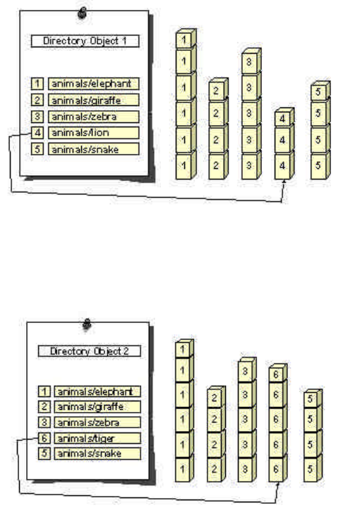
DIGITAL RADIO GUIDE APPENDIX A: EUREKA 147
101
In MOT, the "table of contents" function is handled by the MOT Directory Object and its operation
is illustrated below:
If we replace the file animals/lion with a new file called animals/tiger, the carousel would then
appear as shown below:
The receiver can tell that the carousel has changed because the Directory Object has a new
version, and by comparing the old and new Directory Objects, it can immediately determine that
the file animals/lion has been replaced by animals/tiger.
The MOT Directory Object serves two functions:
To provide reliable management of the files so that any changes to the carousel are understood
by the receiver.
To provide a name and other information for each file so that it may be accessed by an
application.
Dynamic Label
This application carries text information and control characters with a length up to 128 characters
in the PAD channel. It requires a simple alphanumeric text display of 2 lines, 32 characters each.

DIGITAL RADIO GUIDE APPENDIX A: EUREKA 147
102
If the length of the text to be displayed is longer than 64 characters, the text can be incremental
or scrolling.
Broadcast Website
BWS is a local interactive service; the user selects information already received by a browser.
This “radio web” service allows the access to a limited number of websites, as chosen by the
broadcaster (“walled garden”). BWS can be rendered either by a PC or a car navigation platform
using a ¼ VGA display (320 x 240 pixels). HTML version 3.2 and a storage capacity of 256 kB
are required.
Slide Show
This application involves sequences of still pictures (JPEG or PNG). The order and presentation
time of this service are generated by the broadcaster. The transmission time depends primarily
on the file sizes of the pictures and the chosen PAD data rate. For example, a CD cover coded as
JPEG 320 x 240 requires a transmission time of 22s (PAD or packet mode data rate of 16 kbps is
assumed). No local interaction is required.
A visual component, associated with audio, would potentially greatly help radio advertisers to
increase advertising revenue. For example, instead of talking about the new model Volvo had just
released, it would be good if we could see some pictures while we hear about its great features.
Electronic Programme Guide (EPG)
The DAB Electronic Programme Guide (EPG) allows programmers to signpost on a screen on the
radio their key music positions, programmes and benchmark features, and set up opportunities to
record or auto-retune the radio to their station.
Schedules can be sent to the receiver several days in advance of broadcasts, allowing
opportunity to highlight and lock listeners into a new on-air activities early on. They can also be
updated frequently to reflect last-minute changes to on-air output.
Experience of Television EPGs show that they can build station loyalty and time spent watching,
and provide a significant enhancement to recall of on-air promotional trails.
It is expected that the EPG will become a standard feature on many DAB Digital Radios, as it has
become a worldwide technical standard that can be freely adopted by receiver manufacturers.
The EPG was the result of a two-year task force made up of broadcasters and receiver
manufacturers working together within WorldDAB, the forum that promotes development of Digital
Radio to the Eureka 147 standard.
As in TV, EPG will be useful to help to user to find, preview, select, listen and record radio
programmes, particularly if there are many, possibly several hundreds, radio programmes in a
given area.20 The EPG will be used to provide programme listings information for both audio and
data services and as a mechanism for the user to select services, programmes and related
content. A key requirement is that the EPG must work on a range of receivers with differing
display capabilities, resources and back-channel capabilities. To achieve this, a flexible multi-
layer structure has been defined. The EPG data is broken down into service information
(ensembles and services) and programme information (schedules, programmes, groups and
20 Currently there are 320 DAB radio programmes on air in the UK, including 50 in London.

DIGITAL RADIO GUIDE APPENDIX A: EUREKA 147
103
events). Additionally programmes and events can be linked together into groups (e.g. for
grouping programmes together into serials or series).
EPG will be useful to promote new programmes and to attract new listeners. It is also enable for
future technologies such as Personal Media Recording (DAB equivalent of PVR). Manual or
automatic time-shifting of the programme will be possible for the user to choose what and when
they want to listen.
An EPG standard “XML Specification for DAB Electronic Programme Guide” is being developed
by WorldDAB.21 Work is still continuing into the transportation and compression of the EPG data.
EPG is currently being broadcast experimentally on 8 multiplexes in the UK.
DAB Virtual Machine (DAB Java)
Analogous to DVB Multimedia Home Platform (MHP), but suitably scaled down to fit into narrow-
band DAB channel, DAB Java provides a flexible and extendible platform (middleware) for all new
DAB data services. DAB Java is standardised by ETSI.22 The platform enables the rapid
implementation and deployment of new business ideas by enabling the applications (and applets)
to access DAB resources. Future data services for DAB will be realized most efficient based on
DAB Java in terms of time to market and platform independence. This approach enables DAB to
be integrated in large scaled Java – based software environments, e.g. cars using widely
accepted standards.
The concept of virtual machine has been chosen to allow for execution of any DAB applications
independently of the hardware specific configuration. The DAB Java Framework is divided in
three basic modules or packages: a) a DAB-specific extension of the Java API, b) a runtime
support for the DAB applications execution environment, and c) a DAB I/O package for signalling
the DAB Java extension over the DAB signal.
End-to-end reference implementations have been successfully developed to demonstrate the
benefits and new possibilities of DAB Java. These implementations include an EPG application, a
BWS application, a stock market ticker and some local-interactive games. The BBC has
developed an interactive DAB Java – based application "Composer Biographies." Bosch has
demonstrated an integration of DAB Java in an OSGI-based telematics system (GPS device).
21 TS 102 818 v1.1.1 Digital Audio Broadcasting (DAB); XML Specification for DAB Electronic Programme Guide (EPG),
ETSI
22 TS 101 993 V1.1.1 (2002-03) Digital Audio Broadcasting (DAB);A Virtual Machine for DAB: DAB Java Specification,
ETSI
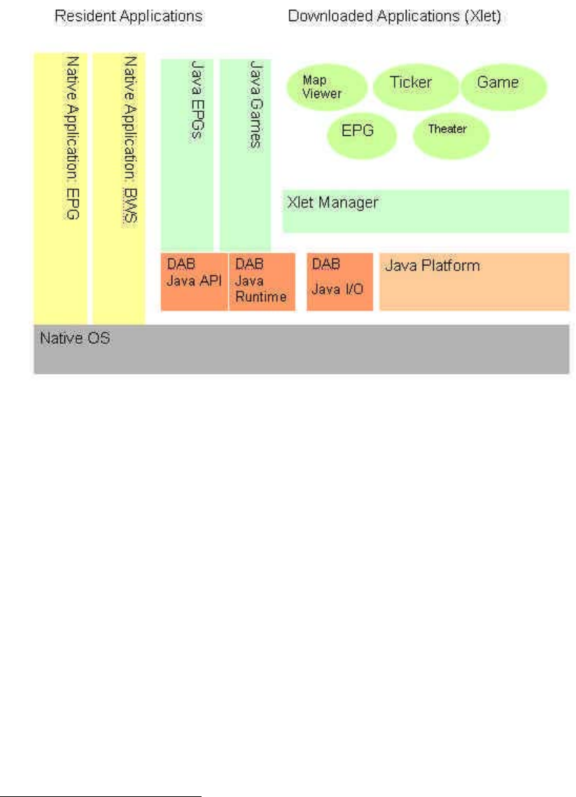
DIGITAL RADIO GUIDE APPENDIX A: EUREKA 147
104
Figure A.1 below shows the architecture of DAB Java.
Figure A.1
The development and implementation of DAB Java requires close cooperation of content, service,
network providers and terminal manufacturers.
DAB Receiver Interfaces
In order to introduce new applications in the mature market with millions of DAB receivers
deployed, it is essential to allow the legacy receivers to connect to the new application decoders
via an agreed interface. To this end, The WorldDAB Forum has developed a specification for the
Receiver Data Interface (RDI).23 Nevertheless, as RDI has some technical limitations (e.g.
flexibility, fixed bandwidth), it has been decided to develop a new interface. The WorldDAB Forum
and the DRM Forum have agreed to cooperate in defining a generic physical USB interface for all
digital radio receivers. Furthermore, a generic low level driver interface based on Digital
Command Set for Receivers (DRCS) specification will be developed, taking into account of copy
protection and digital rights management issues.
Conditional Access
The DAB system already includes a comprehensive conditional system (see Chapter 9 of EN 300
401). Further work is now underway to develop a simple, yet reliable system to be used in
23 EN 50255 Digital Audio Broadcasting system; Specification of the Receiver Data Interface (RDI), CENELEC

DIGITAL RADIO GUIDE APPENDIX A: EUREKA 147
105
commercial receivers using a common scrambling algorithm and a common receiver interface,
however allowing the use of different commercial CA systems such as Simulcrypt and Multicrypt.
SBR Layer II
Spectrum Band Replication (SBR) is a process, proposed by Coding Technologies and now
standardised within MPEG-4 Audio, designed to potentially improve spectrum efficiency of the
DAB system by reducing the audio bit rate for the same quality, while retaining backwards
compatibility. Some initial studies indicate that about 30% improvement could be achieved.
The EBU Project group B/AIM (Audio In Multimedia) is carrying studies on error sensitivity and
compatibility with non-SBR receivers. Some preliminary results show that the inclusion of SBR in
the DAB system does not significantly degrade the C/N performance of the DAB system, neither
in terms of Threshold of Audibility (TOA) nor Point of Failure (POF).
Studies are continued on balancing the benefits and drawbacks of SBR. The matters to be
addressed involve the increase of complexity (and thus cost) of the receiver and the related IPR
issues. No decision has been taken by the WorldDAB Forum to date about the viability of using
including SBR into the standard and recommending its incorporation into commercial receivers.
File caching in the receiver
The WorldDAB Forum has now established a specification for using an optional caching facility in
the receiver. The user will benefit from a so-called "rewind radio," which will allow listening of the
latest programme at any time. The caching device will also allow the user to use the DAB receiver
as a PVR (Personal Versatile Recorder) device for time-shifted playout of audio events (with or
without associated data). It should be pointed out the use of caching may change the way how
people access and enjoy radio listening. It potentially widens the programming possibilities
offered by the broadcaster but also introduces new technical and operational problems (copyright,
EPG, etc).
In September 2003 RadioScape which specialises in digital radio software launched a new
module called RS200L.24 One of the features of this module is the inclusion of Rewind Radio that
enables about ten minutes of audio to be stored on chip RAM. This can be used to listen to a
news clip again or time shift by pausing and resuming the radio. The module has been designed
using the DRE200 chip from Texas Instruments, which is probably one of the world's best selling
receiver chips for the EU 147 standard. This chip has now been superseded by a new version,
DRE310,25 that can decode more than one channel simultaneously and includes time-shifted
radio, announcement support, service linking (FM/DAB ensemble switching), TII (Transmitter
Identification Information) and MP3/Windows Media Audio CD support.
TopNews
TopNews is a commercial name for Bosch/Blaupunkt's system which allows broadcasters (and
multiplex providers) to download via a suitable DAB data channel (e.g. MOT, MSC packet mode)
the news and other audio files or other objects coded in MP3 to the receiver.26 The user is
appropriately informed of the existence of these audio objects and could access them at their
convenience. The broadcaster is responsible for contents and needs to update the audio file
24 http://www.worlddab.org/pressreleases/RADIOSCAPE-LAUNCHES-THE-RS200L.pdf
25 http://www.worlddab.org/pressreleases/TI-uses-Radioscape-23-06-03.pdf
26 WorldDAB TC 075 available from http://www.worlddab.org/tc_presentations/2

DIGITAL RADIO GUIDE APPENDIX A: EUREKA 147
106
contents regularly. There is no need for return link to the service provider. This "audio anytime"
system is particularly attractive for in-car applications.
IP datacasting in DAB
The DAB system is capable of carrying IP packets (datagrams) using IP/UDP protocol.27 As
these packets travel unidirectionally from a service provider to many users simultaneously, this is
a form of IP Multicasting, e.g., pushing the same contents to several users concurrently. The IP
datagrams are tunnelled through a DAB packet mode service component (SC). This is done by
encapsulating the IP datagram in an MSC data group on packet mode transport level. It is not
necessary to establish a connection between the transmitter and the user prior to the
transmission of data.
For connection oriented point-to-point transport, TCP has to be used (rather than UDP). TCP
requires an interaction channel for the return flow of acknowledgements.
Further work is necessary to be carried out similar to that performed by the DVB-IPI project in
order to specify the discovery and selection of the data services by the user.
The Digital Video Broadcasting (DVB) Project has developed a data broadcasting standard
describing an IPv4 and IPv6 datagrams encapsulation in MPEG-2 transport stream. This system
is commonly called Multi-Protocol Encapsulation (MPE) or Data Piping28 and includes dynamic
address resolution, multicast group membership and other supporting procedures and protocols.
The overhead due to encapsulation is reasonably low, e.g., below 3%.
IP datacasting is an interesting option for the DAB systems required to work with IP-enabled
devices such as mobile phones and PDAs. The IP layer could be used as a common
communications layer between the two systems. IP datacasting over DAB will bring the data
content such as moving pictures, audio, web pages, computer programmes and software
upgrades reliably to each user (or a group of users) and will thus expand significantly market
opportunities of DAB. IP datacasting will pave the way towards the personalisation of broadcast
services.
TPEG transport in DAB
It is well known to all broadcasters that radio is an ideal (and the cheapest) medium to inform
travellers about the road conditions and traffic jams – provided that such information is timely and
relevant, in the correct location. Currently analogue FM radio uses a well-established RDS-TMC
(Traffic Message System) system. However, the TMC is essentially limited to inter-urban road
events and every decoder must have a location database to interpret any message received.
TPEG was developed by the EBU to overcome these limitations. TPEG delivers very rich location
referencing information with every message, so that receivers do not need a location database.
Thus, navigation systems which are now becoming a standard commodity in the car can
"machine read" the location content and localise an event directly onto the map display. A text-
only device (such as a PDA) is able to present locally found names such as a railway station
name and a platform number directly to an end user as a text message. Such a message can be
rendered in the language of choice of the end user. TPEG can filter the information to avoid
receiver overload, so that end users can select massages on any number of criteria, such as the
type of location, mode of public transport, direction of travel, event, etc.
27 ES 201 735 V1.1.1 Digital Audio Broadcasting (DAB); Internet Protocol (IP) Datagram Tunnelling
28 EN 301 192 V1.3.1 (2003-05) Digital Video Broadcasting (DVB); DVB specification for data broadcasting

DIGITAL RADIO GUIDE APPENDIX A: EUREKA 147
107
TPEG can be transported within the DAB system in the Transparent Data Channel (TDC) in a
stream-like format; bytes come out in the same order they go in.29 The TDC Specification allows
TPEG data to be carried in three modes: packet mode, stream mode and X-PAD. Nevertheless,
this approach which is specified in the present version of the DAB standard, involves several
problems in terms of reception reliability and interpretation. It has therefore been proposed to
transport TPEG as one of the multimedia applications in the MOT data channel. This would imply
the following main advantages: MOT is already implemented in most receivers and enables
efficient object compression, power saving and delta updates and has much lower overhead than
TDC.
Advanced demodulation technique for COFDM
The Communications Research Centre Canada (CRC) developed an advanced COFDM
demodulation technique30 which reduces the effect of the Doppler effect and therefore increases
the maximum speed, allowing vehicle speeds up to 140 km/s while achieving a target bit error
rate (BER) of 10-4 . Canadian DAB broadcasters use L-Band (1452 to 1492 MHz) and would like
to use Transmission Mode IV instead of Mode II, because the former allows for a larger
separation distance between on-channel re-transmitters than in the case of Mode II. However,
Mode IV in L-Band limits the speed to less than 100 km/h, so this new technique could help.
Further studies are required to investigate whether this technique could be useful for VHF bands
and whether the chip manufacturers could accommodate it readily into their chip design.
Technical Standards
International Standards
ETSI Standards31
Eureka 147 standards are formalised by ETSI and are available for download. The current list of
ETSI standards relating to Eureka 147 are in Table A.3. The main ETSI standard for Eureka 147
is EN 300 401.
Table A.3: ETSI Standards relating to Eureka 147
Number Title
EN 300 401 V1.3.3
(May 2001)
Digital Audio Broadcasting (DAB); DAB to mobile, portable and fixed
receivers
(THIRD EDITION)
EN 300 797 V1.1.1 Digital Audio Broadcasting (DAB); Distribution interfaces; Service
Transport Interface (STI)
EN 300 798 V1.1.1 Digital Audio Broadcasting (DAB); Distribution interfaces; Digital
baseband In-phase and Quadrature (DIQ) Interface
EN 301 234 V1.2.1 Digital Audio Broadcasting (DAB); Multimedia Object Transfer (MOT)
protocol
EN 301 700 V1.1.1 Digital Audio Broadcasting (DAB); Service Referencing from FM-RDS;
29 Guidelines for TPEG in DAB, B/TPEG Plenary Group 00/113 available from www.ebu.ch/bmc_btpeg.htm
30 Thibault, Zhang, Boudreau, Taylor, Chouinard: Advanced Demodulation Technique for COFDM in Fast Fading
Channels, IBC 2003 Proceedings, p. 416 to 422
31 EBU BPN 062

DIGITAL RADIO GUIDE APPENDIX A: EUREKA 147
108
Number Title
Definition and use of RDS-ODA
EN 302 077 V1.1.1 Electromagnetic compatibility and Radio spectrum Matters (ERM);
Harmonised EN for Terrestrial Digital Audio Broadcast (TDAB)
equipment used in the sound broadcasting service.
ES 201 735 Digital Audio Broadcasting (DAB); Internet Protocol Datagram
Tunnelling
ES 201 736 V1.1.1 Digital Audio Broadcasting (DAB); Network Independent Protocols for
Interactive Services
ES 201 737 V1.1.1 Digital Audio Broadcasting (DAB); DAB Interaction Channel through
GSM / PSTN / ISDN / DECT
ETS 300 799 Digital Audio Broadcasting (DAB); Distribution interfaces; Ensemble
Transport Interface (ETI)
TR 101 495 V1.1.1 Digital Audio Broadcasting (DAB); Guide to DAB Standards; Guidelines
and Bibliography
TR 101 496-1 V.1.1.1 Digital Audio Broadcasting (DAB); Guidelines and Rules for
Implementation and Operation
TR 101 496-2 V.1.1.2 Digital Audio Broadcasting (DAB); Guidelines and Rules for
Implementation and Operation
TR 101 496-3 V.1.1.2 Digital Audio Broadcasting (DAB); Guidelines and Rules for
Implementation and Operation
TR 101 497 V1.1.1 Digital Audio Broadcasting (DAB); Rules of Operation for the
Multimedia Object Transfer Protocol
TS 101 498-1 V1.1.1 Digital Audio Broadcasting (DAB); Broadcast Website Application, Part
1:User Application Specification
TS 101 498-2 V1.1.1 Digital Audio Broadcasting (DAB); Broadcast Website Application, Part
2: Basic Profile Specification
TS 101 499 V1.1.1 Digital Audio Broadcasting (DAB); MOT Slide Show; User Application
Specification
TS 101 735 V1.1.1 Digital Audio Broadcasting (DAB); Internet Protocol Datagram
Tunnelling
TS 101 736 V1.1.1 Digital Audio Broadcasting (DAB); Network Independent Protocols for
Interactive Services
TS 101 737 V1.1.1 Digital Audio Broadcasting (DAB); DAB Interaction Channel through
GSM / PSTN / ISDN / DECT
TS 101 756 V1.1.1 Digital Audio Broadcasting (DAB); Registered Tables
TS 101 757 V1.1.1 Digital Audio Broadcasting (DAB); Conformance Testing for DAB Audio
TS 101 758 V2.1.1 Digital Audio Broadcasting (DAB); DAB Signal Strengths and Receiver
Parameters
TS 101 759 V1.1.1 Digital Audio Broadcasting (DAB); DAB Data Broadcasting Transparent
Data Channel
TS 101 860 V1.1.1 Digital Audio Broadcasting (DAB); Distribution Interfaces; Service
Transport Interface (STI); STI Levels
TS 101 993 V1.1.1 Digital Audio Broadcasting (DAB); A Virtual Machine for DAB: DAB
Java Specification
TS 102 818 V1.1.1 Digital Audio Broadcasting (DAB); XML Specification for DAB Electronic
Program Guide (EPG)

DIGITAL RADIO GUIDE APPENDIX A: EUREKA 147
109
Receiver Standards
European receiver standards have been developed by CENELEC, IEC and national standards
bodies (e.g., UK). A list of relevant receiver standards is in Table A.4.
Table A.4: Receiver Standards for Eureka 147
Reference Title
CENELEC EN 50255 Digital Audio Broadcasting system - Specification of the Receiver Data
Interface (RDI)
CENELEC EN 50248 Characteristics of DAB receivers
CENELEC EN 50320 The DAB Command Set for receivers
IEC 62105 Digital Audio Broadcasting System - Specification of the Receiver Data
Interface (RDI)
IEC 62104 Characteristics of DAB Receivers
ITU Publications and Recommendations
The International Telecommunications Union has a number of publications and
Recommendations relating to Eureka 147 and digital radio in particular. The “DSB
Handbook - Terrestrial and satellite DSB to vehicular, portable and fixed receivers in the
VHF/UHF bands” is an aggregation of ITU input documents and data. Relevant recommendations
are in Table A.5.
Table A.5: ITU Recommendations relevant to Eureka 147
Reference Title
BS.1115 Low data rate audio coding
BS.774-2 Service requirements for DSB to vehicular, portable and fixed receivers
using terrestrial transmitters in the VHF/UHF bands
BS.1114-3 Systems for terrestrial DSB to vehicular, portable and fixed receivers in
the frequency range 30-3 000 MHz
BO.789-2 Service for DSB to vehicular portable and fixed receivers for
broadcasting-satellite service (sound) in the frequency range 1 400-2
700 MHz
BO.1130-4 Systems for digital satellite broadcasting to vehicular, portable and fixed
receivers in the bands allocated to BSS (sound) in the frequency range
1 400-2 700 MHz

DIGITAL RADIO GUIDE APPENDIX B: WEBSITES
110
APPENDIX B Relevant World Wide Websites
Advanced Television Systems Committee (ATSC) www.atsc.org
AsiaDAB www.asiadab.org
Asia-Pacific Broadcasting Union (ABU) www.abu.org.my
Audio Engineering Society (AES) www.aes.org
BBC (DAB) www.bbc.co.uk/digitalradio
BBC (Research and Development) www.bbc.co.uk/rd
BBC Training (Centre for Broadcasting Skills) www.bbc.co.uk/woodnorton
BBC World Service (Radio) www.bbc.co.uk/worldservice
Commonwealth Broadcasting Association (CBA) www.cba.org.uk
Crown Castle International www.crowncastle.com
Crown Castle UK www.crowncastle.co.uk
DAB Canada www.digitalradio.ca
Dalet www.dalet.com
Digital Radio Mondiale (DRM) www.drm.org
Digital Video Broadcasting (DVB) www.dvb.org
European Broadcasting Union (EBU) www.ebu.ch
Financial Times (Media and Telecoms.) www.ftmedia.com
Ibiquity (HD Radio) www.ibiquity.com
International Telecommunications Union www.itu.int
Lucent Technologies (Lucent Digital Radio) www.lucent.com
National Association of Broadcasters (US) www.nab.org
National Association of Shortwave Broadcasters US
(NASB)
www.shortwave.org
National Radio Systems Committee US (NRSC) www.nrscstandards.org
National Transcommunications Ltd. (NTL) www.ntlradio.com
North American Broadcasters Association (NABA) www.nabanet.com
Office of Communications UK (Ofcom) www.ofcom.org.uk
Radio Academy (UK) www.radioacademy.org
Real Audio www.real.com
Roke Manor Research (UK) www.roke.co.uk
Sadie www.sadie.com
Sirius Satellite Radio www.siriusradio.com
Thales Broadcast www.thales-bm.com

DIGITAL RADIO GUIDE APPENDIX B: WEBSITES
111
World Broadcasting Unions (WBU) www.worldbroadcastingunions.org
World Radio Network www.wrn.org
WorldDAB www.worlddab.org
WorldSpace Radio www.worldspace.com
XM Satellite Radio www.xm.com
DIGITAL RADIO GUIDE APPENDIX C: ACRONYMS
112
APPENDIX C Glossary of Acronyms
AAC Advanced Audio Coding
AAS Advanced Application Services
ADR Astra Digital Radio
AM Amplitude Modulation
API Advanced Programming Interface
ATM Asynchronous Transfer Mode
BBC British Broadcasting Corporation
BER Bit Error Rate
Bit Binary digit
Bitrate Rate of flow of bits per second
BSS(S) Broadcast satellite services (Sound)
BWS Broadcast Website
CA Conditional Access
CBC Canadian Broadcasting Corporation
CCETT Centre Commun d’Etudes de Telediffusion et Telecommunication (Research
Laboratories of France Telecom and Telediffusion de France)
CD Compact Disc
CDMA Code Division Multiple Access
CEG Consumer Equipment Group
CELP Code Excited Linear Prediction
CEMA Consumer Electronics Manufacturers Association
CEPT European Conference of Postal and Telecommunications Administrations
codec Coder / Decoder
COFDM Coded Orthogonal Frequency Division Multiplex
CP Continual Pilot
CRC Communications Research Centre Canada
CRTC Canadian Radio-television and Telecommunications Commission
DAB Digital Audio Broadcasting
DARS Digital Audio Radio Service
DAT Digital Audio Tape
DAW Digital Audio Workstation
DMB Digital Multimedia Broadcasting
DQPSK Differential Quadrature Phase Shift Keying
DIGITAL RADIO GUIDE APPENDIX C: ACRONYMS
113
DRB Digital Radio Broadcasting
DRDB Digital Radio Development Bureau
DRM Digital Radio Mondiale
DRP Digital Radio Promotion
DSB Double Side Band
DSL Digital Subscriber Line
DSR Digital Satellite Radio
DTH Direct to Home
DTS Digital Theatre System
DTT Digital Terrestrial Television
DVB Digital Video Broadcasting
DVB-H Digital Video Broadcasting – Handheld
DVB-T Digital Video Broadcasting – Terrestrial
DXB Digital Extended Broadcasting, a German-funded project
EBU European Broadcasting Union
EIA Electronic Industries Alliance (formerly Electronic Industries Association)
EMK Electronic Media Kiosk
EPG Electronic Program Guide
ETI Ensemble Transport Interface
ETS European Telecommunications Standard
ETSI European Telecommunications Standards Institute
Eureka European R and D programme
FAC Fast Access Channel
FCC Federal Communications Commission (US)
FIC Fast Information Channel
FM Frequency Modulation
FDMA Frequency division multiple access
FHG Fraunhofer Institute (Germany)
FIC Fast Information channel
GPS Global Positioning System
GSO Geostationary (Satellite) Orbit
GSM Global System for Mobile Communications
HEO Highly Elliptical Orbit
HVXC Harmonic Vector Excitation Coding
DIGITAL RADIO GUIDE APPENDIX C: ACRONYMS
114
IEEE Institute of Electrical and Electronics Engineers
IFPI International Federation of the Phonographic Industry
iMP Integrated Media Player
IP Internet Protocol
ISDB-TSB Integrated Services Digital Broadcasting – Terrestrial for Sound Broadcasting
ITU International Telecommunications Union
ITU-R ITU Radiocommunications Sector
IBAC In-Band Adjacent Channel
IBOC In-Band / On-Channel
JPEG Joint Photographic Experts Group
kbps 1000 bits per second
LCD Liquid Crystal Display
LF Low Frequency
LW Long wave
LEO Low earth orbit (satellite)
MATS Mobile Aeronautical Telemetry Services
MCI Modular Control Interface
MD Mini Disc
MDI Multiplex Distribution Interface
MF Medium Frequency
MHP Multimedia Home Platform
MLC Multi-Level Coding
MP3 MPEG Audio Layer 3 (see MPEG)
MPEG Moving Pictures Expert Group
MPS Main Program Service
MOT Multi-media Object Transfer
MSC Main Service Channel
MW Medium wave
NAB National Association of Broadcasters (US)
NHK Nippon Hoso Kyokai (Japan Broadcasting Corporation)
NICAM 728 Near-Instantaneously Companded Audio Multiplex (728 is bit rate in kbps)
NRSC National Radio Systems Committee (an industry sponsored technical standard
setting body, co-sponsored by CEMA and NAB in the US)
OEM Original Equipment Manufacturer
OFDM Orthogonal Frequency Division Multiplexing
DIGITAL RADIO GUIDE APPENDIX C: ACRONYMS
115
P2P Peer-to-Peer Networking
PAD Programme Associated Data
PC card A plug in card for a Personal Computer, which allows it to receive DAB.
PDA Personal Digital Assistant
PNG Portable Network Graphics
POF Point of Failure
PTY Programme Type Codes
PVR Personal Versatile Recorder
QAM Quadrature Amplitude Modulation
QPSK Quadrature Phase Shift Keying
RAM Random Access Memory
RDS Radio Data System
RDI Receiver data Interface
RF Radio Frequency
RSCI Receiver Status and Control Interface
SBR Spectral Band Replication
SCA Subsidiary Communications Authorization
SDC Service Description Channel
SDI Service Distribution Interface
SFN Single Frequency Network
S-DAB Satellite DAB
SDARS Satellite Digital Audio Radio Service
S-DMB Satellite Digital Multimedia Broadcasting
SIS Service Information Service
SLS Slideshow
SMIL Synchronized Multimedia Integration Language
SR Sveriges Radio (Swedish Radio)
SSB Single Side-Band
STL Studio-to-Transmitter Link
SW Short-wave
Simulcasting Simultaneous transmission of a programme
T-DAB Terrestrial DAB
TCM Trellis coded Modulation
TDC Transparent Data Channel
DIGITAL RADIO GUIDE APPENDIX C: ACRONYMS
116
TDM Time Division Multiplex
TDMA Time Division Multiple Access
T-DMB Terrestrial Digital Multimedia Broadcasting
TMC Traffic Message System
TMCC Transmission and Multiplexing Configuration Control
TOA Threshold of Audibility
TPEG Transport Protocol Experts Group
TTSL Total Time Spent Listening
UEP Unequal Error Protection
USB Universal Serial Bus
VHF Very high Frequency
VPN Virtual Private Networks
VRT Belgian Public Service Broadcaster
W(A)RC World (Administrative) Radio Conference
WiFi Wireless technology brand (coined by WiFi Alliance)
WiMAX Worldwide Interoperability for Microwave Access
WMA Windows Media Audio
WorldDAB Organisation for promoting digital radio (DAB) based on the Eureka 147 system.
117
DISCLAIMER
The information in the World Broadcasting Unions Technical Committee (WBU-TC) Digital Radio
Guide is for general information purposes only. While the WBU makes every effort to provide
content that is correct, accurate, and timely, the WBU makes the Digital Radio Guide and its
content available without warranties of any kind. The WBU does not control or guarantee the
accuracy, relevance, timeliness or completeness of this information. Further, the inclusion of
references and links to particular items in the Digital Radio Guide are not intended to reflect their
importance, nor is it intended to endorse any views expressed or products or services offered on
these outside references, or the organization sponsoring them. The information provided in this
guide have been prepared for convenience of reference only. ALL DOCUMENTS AND
INFORMATION IN THE WBU-TC DIGITAL RADIO GUIDE ARE NOT INTENDED FOR
REDISTRIBUTION IN ANY WAY, SHAPE OR FORM. THE CONTENTS OF THE WBU-TC
DIGITAL RADIO GUIDE (INCLUDING ITS DESIGN AND ELEMENTS) AND ANY
PUBLICATIONS ARE THE PROPERTY OF THE WBU AND/OR THE SUPPLIER AND MAY NOT
BE REPRODUCED, REDISTRIBUTED, OR USED IN WHOLE, OR IN PART, WITHOUT THE
PRIOR WRITTEN CONSENT OF THE WBU AND/OR THE SUPPLIER.
The WBU makes every effort to abide by the agreement(s) outlined by third party providers for
their content. Unless specifically informed of any changes to user agreements, the content shall
remain in the Digital Radio Guide with the understanding that the original agreement(s) (dated up
to April 2007) have remained in tact and unaltered in any way. The provider of the third party
content is responsible for contacting the WBU directly if any agreement(s) are altered in any way.
The WBU will not be held responsible if the content provider fails to contact the WBU regarding
changes to the agreement(s). Reproduction of any aspect of the Digital Radio Guide or its
contents in any way, shape or form is strictly prohibited without the explicit written consent of the
WBU and/or the content provider.
Copyright © 2007 World Broadcasting Unions Technical Committee. All rights reserved.
