Gsi Outdoors Pneg 630 Users Manual New 630a
PNEG-630 to the manual 3088b64c-8c8b-409d-9571-08cc4705fb55
2015-02-09
: Gsi-Outdoors Gsi-Outdoors-Pneg-630-Users-Manual-562931 gsi-outdoors-pneg-630-users-manual-562931 gsi-outdoors pdf
Open the PDF directly: View PDF ![]() .
.
Page Count: 121 [warning: Documents this large are best viewed by clicking the View PDF Link!]

2004 Revised Edition
PNEG-630
Troubleshooting and
Reference Manual
GSI
Competitor & EMCS
Portable Dryer
Models
Competitor Series 2000 Dryer

Portable Dryer Troubleshooting
1
Table Of Contents
Safety ..................................................................................................................................................................... 3
Safety Sign Off Sheet ............................................................................................................................................ 8
EMCS Portable Dryer (1993-1998)
Safety Voltage Check Points ................................................................................................................................. 9
Programming Instructions for EMCS Grain Dryers .............................................................................................. 10
EMCS Display Board ............................................................................................................................................ 11
Input/Output Board Identification .......................................................................................................................... 12
EMCS Switch Replacement.........................................................................................................................13
1100 Series Control Box Wiring ............................................................................................................................. 14
1100 Series Control Box Wiring (New) ................................................................................................................. 15
1200 Series Control Box Wiring............................................................................................................................. 16
1200 Series Control Box Wiring (New) ................................................................................................................. 17
1100 Fan Lower Control Box Interconnect Strip ................................................................................................... 18
1200 Fan Lower Control Box Interconnect Strip .................................................................................................. 19
Upper Control Box External Wiring....................................................................................................................... 20
Fan Housing and Vapor Hi-Limit Circuit ............................................................................................................... 21
Plenum Hi-Temperature Switch ............................................................................................................................ 22
Fixed Grain Hi-Limit .............................................................................................................................................. 23
Grain & Plenum Hi-Limit Circuit ........................................................................................................................... 24
Two Fan Plenum and Grain Limit Switch Wiring .................................................................................................. 25
Rear Discharge & Emergency Cooling Circuit ..................................................................................................... 26
Rear Discharge Mercury Switch ........................................................................................................................... 27
Adjustable Hi-Limit & Emergency Cooling Circuit ............................................................................................... 28
Motor Overloads .................................................................................................................................................... 29
Air Pressure Switch............................................................................................................................................... 30
Air Pressure Switch Drawing................................................................................................................................ 31
Out of Grain Safety Circuit .................................................................................................................................... 32
Out of Grain Safety Circuit Drawing ..................................................................................................................... 33
Upper Junction Box Wiring .................................................................................................................................... 34
Meter Roll Sensor .................................................................................................................................................. 35
Meter Roll Sensor Wiring ...................................................................................................................................... 36
Meter Roll Reversing ............................................................................................................................................. 37
Lower Junction Box Wiring ................................................................................................................................... 38
New Fenwal Board Wiring.......................................................................................................................... 39
New Fenwal Board Troubleshooting.............................................................................................................40
Flame Control Circuit ............................................................................................................................................. 41
Fan Burner Circuit for Canadian Models .............................................................................................................. 42
Conversion Diagram for C Series Dryers to a Switchable Hi/Low or On/Off Burner ......................................... 43
Fan 28 LP Hi/Low-On/Off .................................................................................................................................... 44
Fan 28 LP On/Off Burner with Mercoid ............................................................................................................... 45
Fan 28 NG Hi/Low-On/Off ................................................................................................................................... 46
Fan 28 NG On/Off Burner with Mercoid .............................................................................................................. 47
Fan 42 LP Hi/Low-On/Off .................................................................................................................................... 48
Fan 42 LP On/Off Burner with Mercoid ............................................................................................................... 49
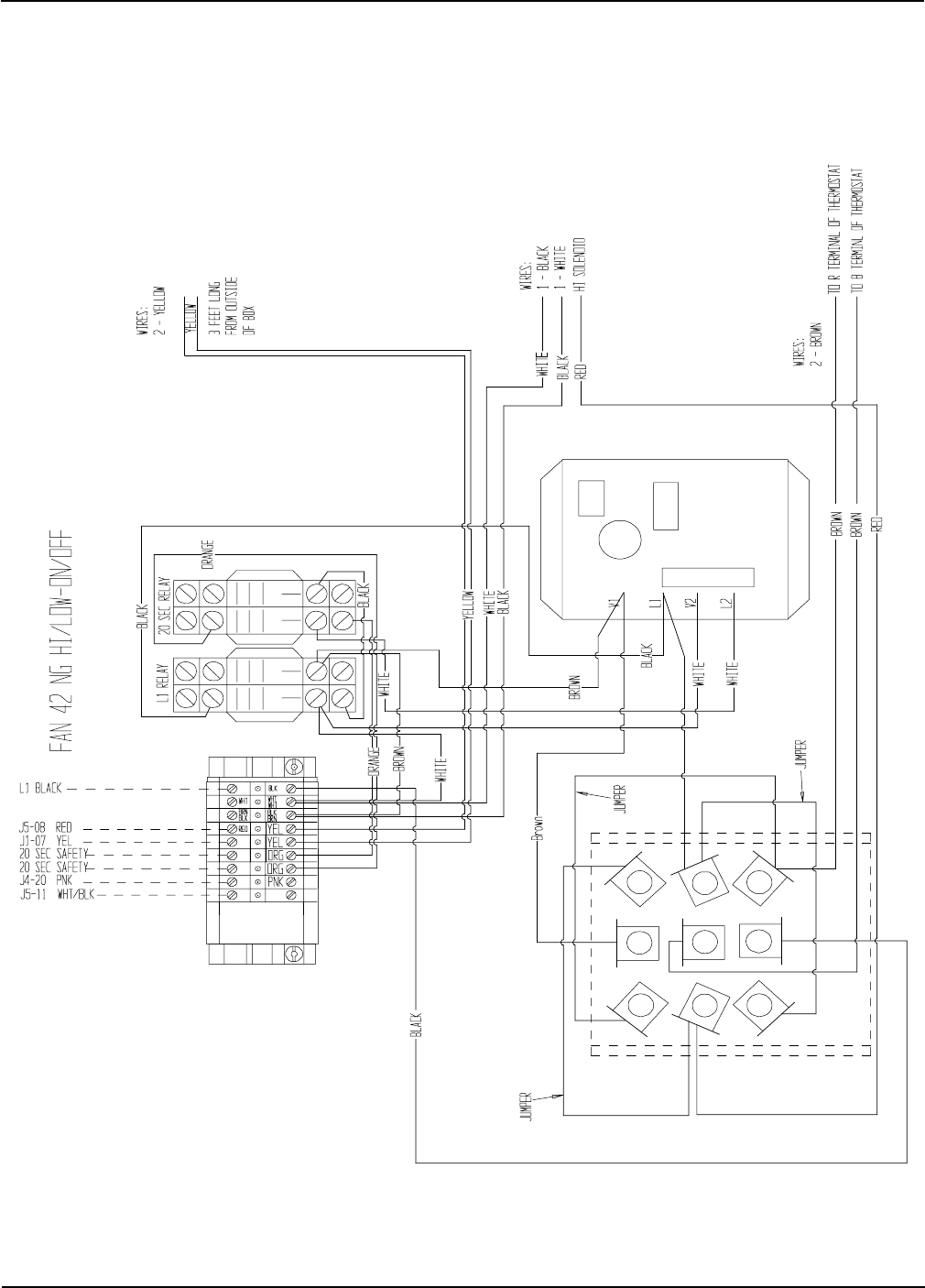
Fan 42 NG Hi/Low-On/Off ................................................................................................................................... 50
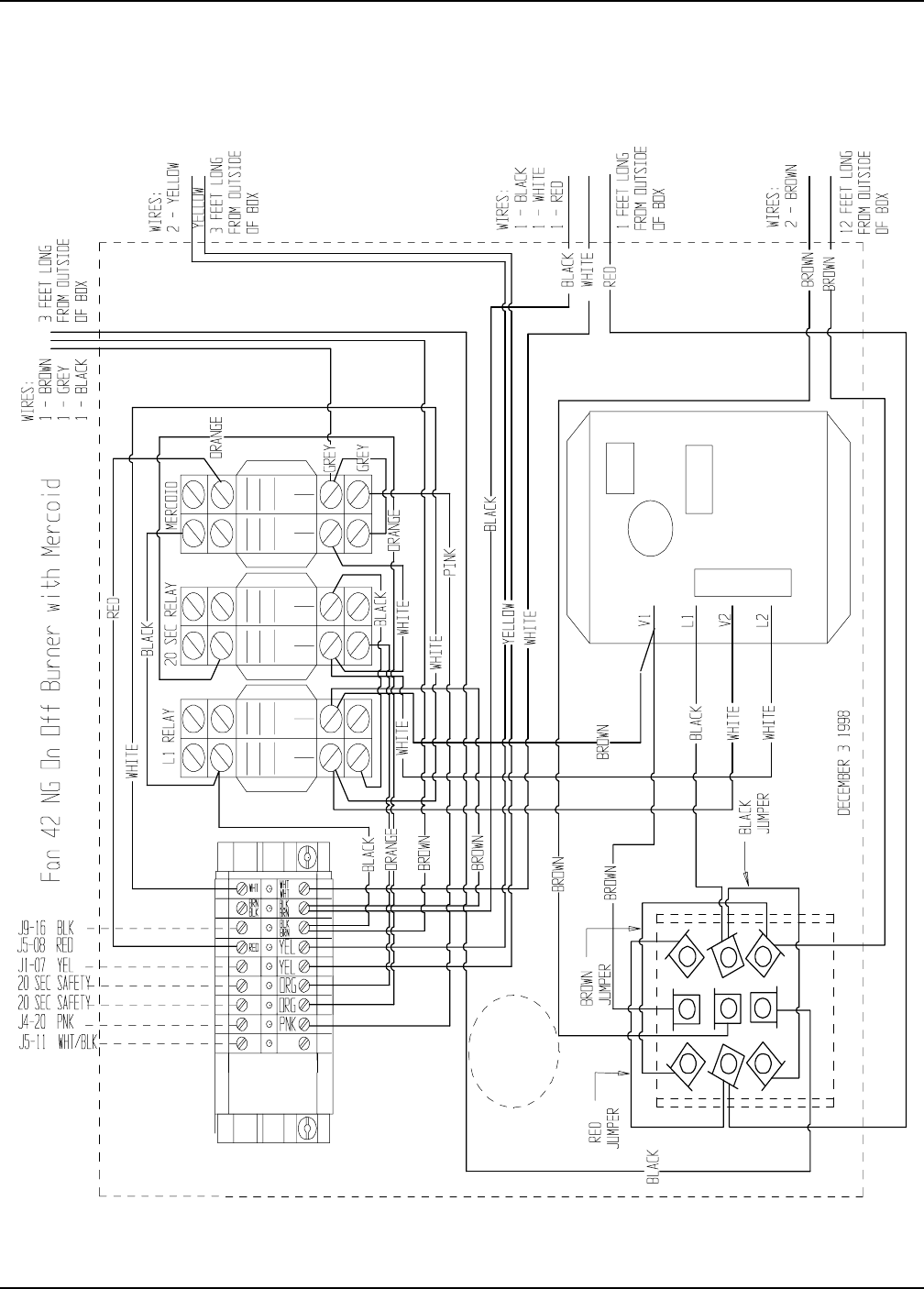
Fan 42 NG On/Off Burner with Mercoid .............................................................................................................. 51
SCR Drive Circuit.................................................................................................................................................. 52
RTD Temperature Sensor...................................................................................................................................... 53
Test Procedure for EMCS Dryers......................................................................................................................... 54
Temperature Charts ............................................................................................................................................... 55
EMCS Troubleshooting Tips........................................................................................................................ 56

Portable Dryer Troubleshooting
2
Table Of Contents
Competitor Series 2000 Dryer (Picture of Dryer)(1995 to Present)......................................................65
220 Volt Single (1) Phase Power Drawing ............................................................................................................ 66
220 Volt Single (1) Phase Power Drawing (New Version) .................................................................................. 67
220 Volt Three (3) Phase Power Drawing ............................................................................................................ 68
220 Volt Three (3) Phase Power Drawing (New Version) ................................................................................... 69
220 Volt 1 Phase Power Circuit (Ladder Diagram)........................................................................................70
220 Volt 3 Phase Power Circuit (Ladder Diagram)........................................................................................71
440 Volt 3 Phase Power Circuit (Ladder Diagram)........................................................................................72
Upper Control Box Internal Wiring ........................................................................................................................ 73
Series 2000 Control Box Wiring (New Version) .................................................................................................... 74
Series 2000 Control Box Wiring............................................................................................................................. 75
Series 2000 Control Box Wiring (380-460-575 3 Phase).................................................................................76
Upper Terminal Strip...................................................................................................................................77
Upper Terminal Strip (Moisture Control Hook-Up)........................................................................................78
Upper Terminal Strip (Moisture Control Relay Hook-Up)...............................................................................79
Moisture Manager to Dryer Wiring...............................................................................................................80
Input/Output Board & Terminal Strip .................................................................................................................... 81
Control Circuit (CPU/Display)(Ladder Diagram)......................................................................................... 82
Control Circuit (I/O Board)(Ladder Diagram)...............................................................................................83
Control Circuit (SCR Drive Board)(Ladder Diagram)....................................................................................84
SCR Board (Installing & Calibrating)............................................................................................................85
Upper Control Box External Wiring....................................................................................................................... 88
Input/Output Board 12 Volt .................................................................................................................................... 89
CPU Board Wiring................................................................................................................................................. 90
Programming Instructions for Competitor Series Grain Dryers ............................................................................ 91
Programming Hook Up Diagram ........................................................................................................................... 92
Back of Switch Panel Layout ................................................................................................................................ 95
Back of Switch Panel Wiring ................................................................................................................................. 96
Air Switch Assembly ............................................................................................................................................. 97
Air Switch Adjusting...................................................................................................................................98
Fixed Grain Hi-Limit & Temperature Sensor ........................................................................................................ 99
Out of Grain Sensor...................................................................................................................................100
Grain Temperature Sensor..........................................................................................................................101
Grain Sensor Testing..................................................................................................................................102
Grain Sensor (Locating,Testing,& Replacing)...............................................................................................103
Sensor Resistance/Temperature Chart.........................................................................................................105
Plenum Sensor (Locating,Testing & Replacing)............................................................................................106
Stern and Capacitor Diagram......................................................................................................................108
Operation Hints..........................................................................................................................................109
Series 2000 Error Conditions.......................................................................................................................111
Heater Circuit............................................................................................................................................113
Fan Burner Circuit for Canadian Models Only..............................................................................................114
Series 2000 LP 26"/28" Fan ........................................................................................................................115
Series 2000 Natural Gas 26"/28" Fan............................................................................................................116
Series 2000 LP 36"/42" Fan.........................................................................................................................117
Series 2000 Natural Gas 36"/42" Fan............................................................................................................118
Warranty....................................................................................................................................................119
Portable Dryer Troubleshooting
3
Safety
WARNING! BE ALERT!
Personnel operating or working
around electric fans should read this
manual. This manual must be
delivered with the equipment to its
owner. Failure to read this manual
and its safety instructions is a
misuse of the equipment.
The symbol shown is used to call your
attention to instructions concerning your
personal safety. Watch for this symbol;
it points out important safety precau-
tions. It means "ATTENTION",
"WARNING", "CAUTION", and "DAN-
GER". Read the message and be cau-
tious to the possibility of personal in-
jury or death.
Safety Alert Symbol
Thank you for choosing an GSI
Grain Dryer. It is designed to pro-
vide excellent performance and ser-
vice for many years.
This manual refers to the trouble-
shooting of the E.M.C.S.and Series
2000 Competitor models. Different
models are available for liquid pro-
pane or natural gas fuel supply, with
either single phase 230 volt, or three
phase 230, 460, 575 volt electrical
power. (Also 380 volt 50Hz).
The GSI Group Inc. recommends
contacting your local power com-
pany, and having a representative
survey your installation so the wir-
ing is compatible with your system
and adequate power is supplied.
The principal concern of the GSI
Group, Inc. ("GSI") is your safety
and the safety of others associated
with grain handling equipment. This
manual is written to help you un-
derstand safe operating proce-
dures, and some of the problems
that may be encountered by the op-
erator or other personnel.
Dryer Safety
Instructions and
Information
As owner and/or operator, it is your responsibility to know what requirements, hazards and precautions exist,
and to inform all personnel associated with the equipment, or who are in the dryer area. Avoid any alterations to
the equipment. Such alterations may produce a very dangerous situation, where serious injury or death may
occur.
Portable Dryer Troubleshooting
4
Safety
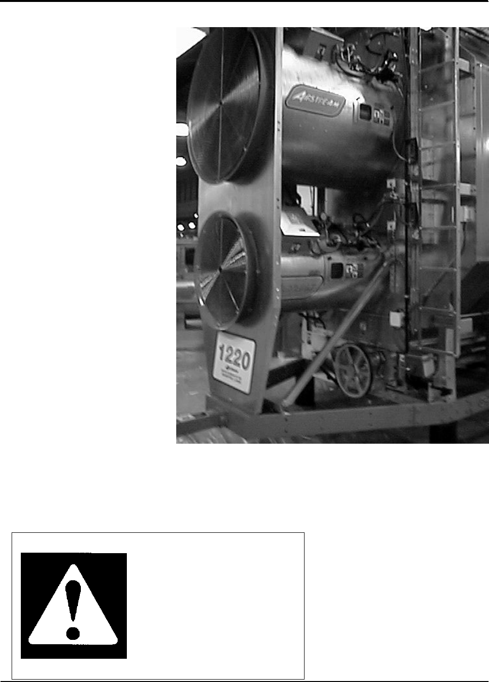
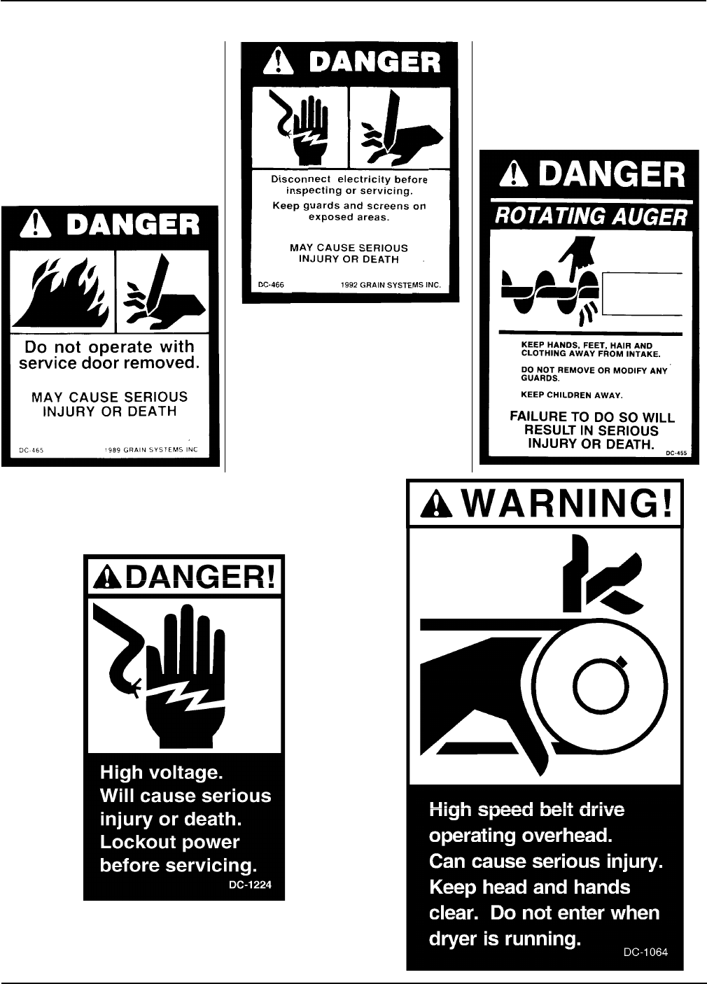
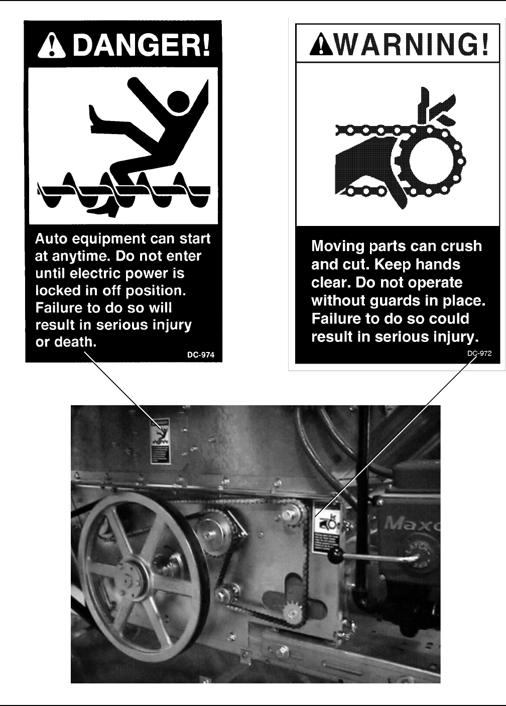
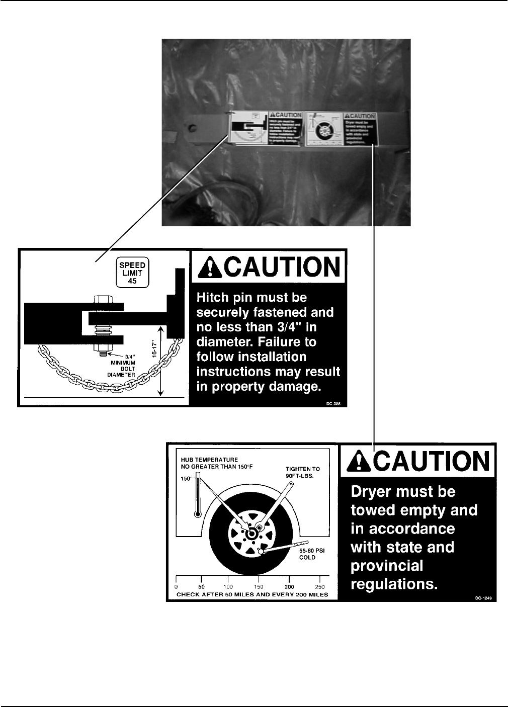
Safety decals should be read and
understood by all people in and
around the dryer area. If the follow-
ing safety decals are not displayed
on your dryer, or if they are dam-
aged, contact Grain Systems, Inc. for
replacement.
A CAREFUL OPERATOR
IS THE BEST INSURANCE
AGAINST AN ACCIDENT
Grain Systems, Inc. recommends
you contact your local power com-
pany and have a representative sur-
vey your dryer installation, so your
wiring will be compatible with their
system and you will have adequate
power supplied to your unit.
Portable Dryer Troubleshooting
5
Safety
Portable Dryer Troubleshooting
6
Safety

Portable Dryer Troubleshooting
7
1. Read and understand the operating manual before trying to operate the
dryer.
2. Power supply should be OFF for service of electrical components. Use
CAUTION in checking voltage or other procedures requiring power to
be ON.
3. Check for gas leaks at all gas pipe connections. If any leaks are de-
tected, do not operate the dryer. Shut down and repair before further
operation.
4. Never attempt to operate the dryer by jumping or otherwise bypassing
any safety devices on the unit.
5. Set pressure regulator to avoid excessive gas pressure applied to burner
during ignition and when burner is in operation. Do not exceed maxi-
mum recommended drying temperature.
6. Keep the dryer clean. Do not allow fine material to accumulate in the
plenum or drying chamber.
7. Use CAUTION in working around high speed fans, gas burners, augers
and auxiliary conveyors which START AUTOMATICALLY.
8. Do not operate in any area where combustible material will be drawn into
the fan.
9. Before attempting to remove and reinstall any propeller, make certain to
read the recommended procedure listed within the servicing section of
the manual.
10. Clean grain is easier to dry. Fine material increases resistance to airflow
and requires removal of extra moisture.
This product is intended for the use of grain handling only. Any other
use is considered a misuse of the product.
Some edges of the product components can be sharp. It is recommended
that each component of this product be examined to determine if there
are any safety considerations to be taken. Any and all necessary personal
protective equipment should be worn at all tines when handling, assem-
bling, installing and operation of the product and/or components.
Guards are removed for illustration purpose only. All guards must be
in place before/during operation.
Use Caution in the
Operation of this
Equipment
The design and manufacture of this
dryer is directed toward operator
safety. However, the very nature of
a grain dryer having a gas burner,
high voltage electrical equipment
and high speed rotating parts, does
present a hazard to personnel, which
can not be completely safeguarded
against, without interfering with ef-
ficient operation and reasonable ac-
cess to components.
Use extreme caution in working
around high speed fans, gas-fired
heaters, augers and auxiliary con-
veyors, which may start without
warning when the dryer is operat-
ing on automatic control.
READ THESE INSTRUCTIONS
BEFORE OPERATION AND SERVICE
SAVE FOR FUTURE REFERENCE
Continued safe, dependable opera-
tion of automatic equipment de-
pends, to a great degree, upon the
owner. For a safe and dependable
drying system, follow the recom-
mendations within this manual, and
make it a practice to regularly in-
spect the operation of the unit for
any developing problems or unsafe
conditions.
Take special note of the safety pre-
cautions listed at left before attempt-
ing to operate the dryer.
KEEP THE DRYER CLEAN
DO NOT ALLOW FINE
MATERIAL TO ACCUMULATE
IN THE PLENUM CHAMBER
OR SURROUNDING THE
OUTSIDE OF THE DRYER
Safety Precautions

Portable Dryer Troubleshooting
8
Date Employer’s Signature Employee
________________________________________________________________________________________________________________________
_________________________________________________________________________________________________________________________
________________________________________________________________________________________________________________
___________________________________________________________________________________________________________________________
________________________________________________________________________________________________________________________
_____________________________________________________________________________________________________________________________
__________________________________________________________________________________________________________________________
_______________________________________________________________________________________________________________________________
_____________________________________________________________________________________________________________________________
______________________________________________________________________________________________________________________________
___________________________________________________________________________________________________________________________
______________________________________________________________________________________________________________________
_________________________________________________________________________________________________________________________
_____________________________________________________________________________________________________________________
______________________________________________________________________________________________________________________
_________________________________________________________________________________________________________________________
______________________________________________________________________________________________________________________
_______________________________________________________________________________________________________________________
______________________________________________________________________________________________________________________
______________________________________________________________________________________________________________________
_____________________________________________________________________________________________________________________
________________________________________________________________________________________________________________________
______________________________________________________________________________________________________________________
_____________________________________________________________________________________________________________
_______________________________________________________________________________________________________________________
_____________________________________________________________________________________________________________________
___________________________________________________________________________________________________________________
Safety Sign-Off Sheet
Portable Dryer Troubleshooting
9
FAN # 12345 6
Error Message - + - + - + - + - + - + RESULT
Fan # Housing High Temperature J5-12 J1-7 J5-12 J1-8 J5-12 J2-7 J5-12 J2-8 J5-12 J3-7 J5-12 J3-8 12VDC
Burner # Vapor High Temperature J5-12 J1-5 J5-12 J1-6 J5-12 J2-5 J5-12 J2-6 J5-12 J3-5 J5-12 J3-6 12VDC
Burner # Flame not Detected J5-12 J1-9 J5-12 J1-10 J5-12 J2-9 J5-12 J2-10 J5-12 J3-9 J5-12 J3-10 12VDC
Plenum # High Temperature J5-12 J1-11 J5-12 J1-12 J5-12 J2-11 J5-12 J2-12 J5-12 J3-11 J5-12 J3-12 12VDC
Burner # Shutdown Loss of Airflow J5-12 J1-13 J5-12 J1-14 J5-12 J2-13 J5-12 J2-14 J5-12 J3-13 J5-12 J3-14 Note 1
Fan # Failure No Airflow J5-12 J1-13 J5-12 J1-14 J5-12 J2-13 J5-12 J2-14 J5-12 J3-13 J5-12 J3-14 Note 2
Fan # cannot Start Check Air Switch J5-12 J1-13 J5-12 J1-14 J5-12 J2-13 J5-12 J2-14 J5-12 J3-13 J5-12 J3-14 Note 3
1100/1200/1300 2200/2300/2400 3300/3400/3600
Lower or Left Fixed Grain J5-12 J1-19 J5-12 J1-19 J5-12 J1-19
Lower Adjustable or Right Fixed Grain J5-12 J4-19 J5-12 J4-19 J5-12 J4-19
Middle Fixed Grain J5-12 N/A J5-12 N/A J5-12 J4-4
Middle Adjustable Grain J5-12 N/A J5-12 N/A J5-12 J4-8
Upper Fixed Grain J5-12 N/A J5-12 J4-4 J5-12 J4-2
Upper Adjustable Grain J5-12 N/A J5-12 J4-8 J5-12 J4-6
Misc Errors
Auxilliary Safety Shutdown J5-12 J1-20 Note:
Motor Overload J5-12 J4-12 1 This error will occur if the fan and burner were both operating and
Grain Discharge Warning J5-12 J5-5 the air switch opens which indicates loss of static pressure.
Maxon Valve Shut Warning J5-12 J5-2 12 volts should be present if the fan is on.
Unknown Safety Error J5-12 J5-10 2 This error will occur if after the fan has started the air switch does
20 Second Safety Circuit Failure J5-12 J5-6 not detect any static pressure. 12 volts should be present if
the fan is on.
3 The condition for this error will occur if the air switch is stuck
in the closed postition. No voltage should be present if the
dryer is stopped.
Wiring Reference
Safety Voltage Check Points

Portable Dryer Troubleshooting
10
Programming Instructions for EMCS Grain Dryers
Programming
1. Turn Control Power on dryer to off.
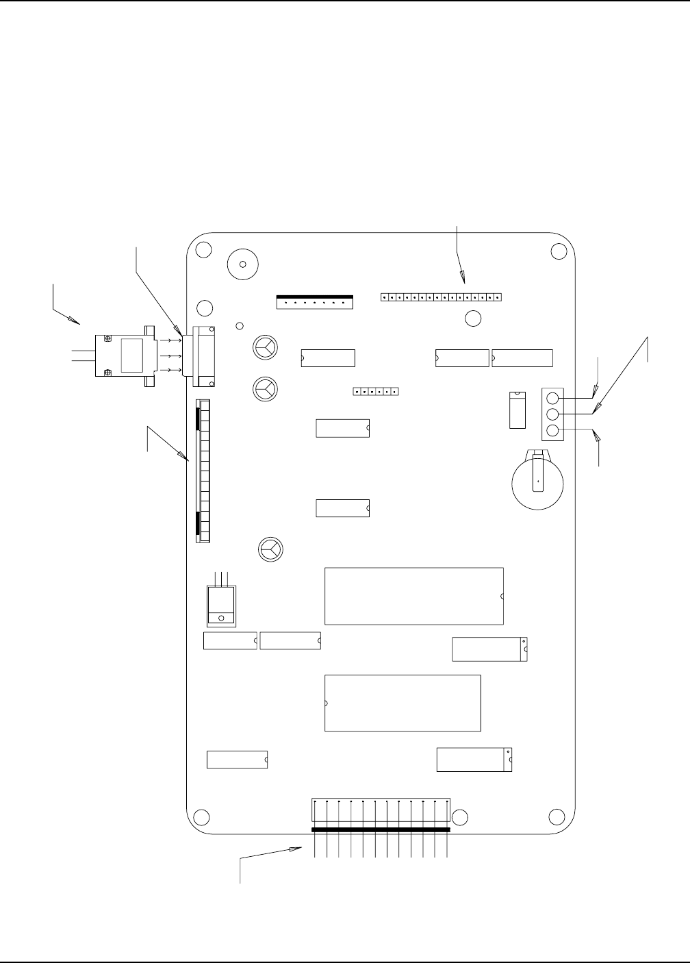
2. Locate programming jack (P7) on back of computer. (See page 13).
3. Plug the DB-9 jack of the programmer into the computer's jack.
4. Be sure that the rotary switch on the programmer is set to position 8.
5. Turn on Control Power to the dryer.
6. The four (4) lights on the programmer will come on, then three (3) will go out leaving the power light still on.
7. Push the start button on the programmer to start the transfer of Software.
8. The busy light will flash until the transfer process is complete.
9. When completed the pass light will flash indicating a successful transfer.
10. If the fail light flashes then check your connections and repeat the above process.
11. Turn Control Power on dryer to off and remove the cable.
12. Turn on the dryer and the opening screens should indicate the newer version of software.
Portable Dryer Troubleshooting
11
TO STOP SW.
TO START SW.
TO START &
STOP SWS.
3
21
DISPLAY
RIBBON S1
U12 P3
COMMUNICATIONS CABLE
TO I/O BOARD
P5
P4
KEY PAD RIBBON
SOUND
BATTERY (TIC)
P7
P8
P1
P6
COMPUTER
PROGRAMMING
JACK
PROGRAMMER
JACK (DB9)
EMCS Display Board
Programming
Portable Dryer Troubleshooting
12
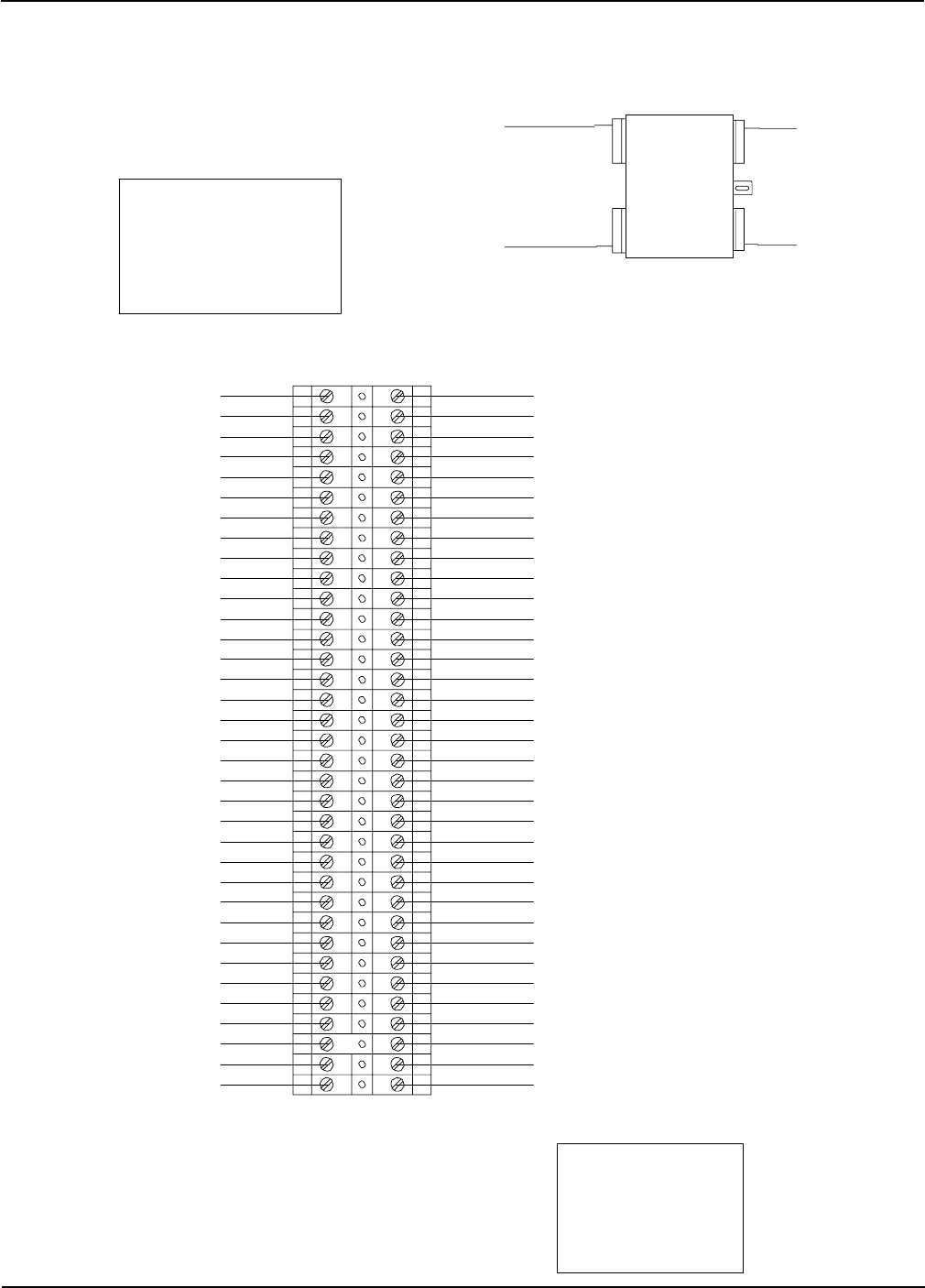
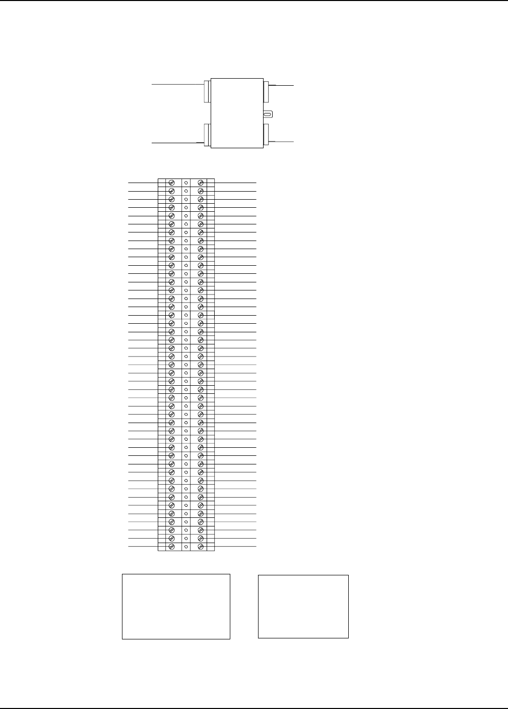
Wiring Reference
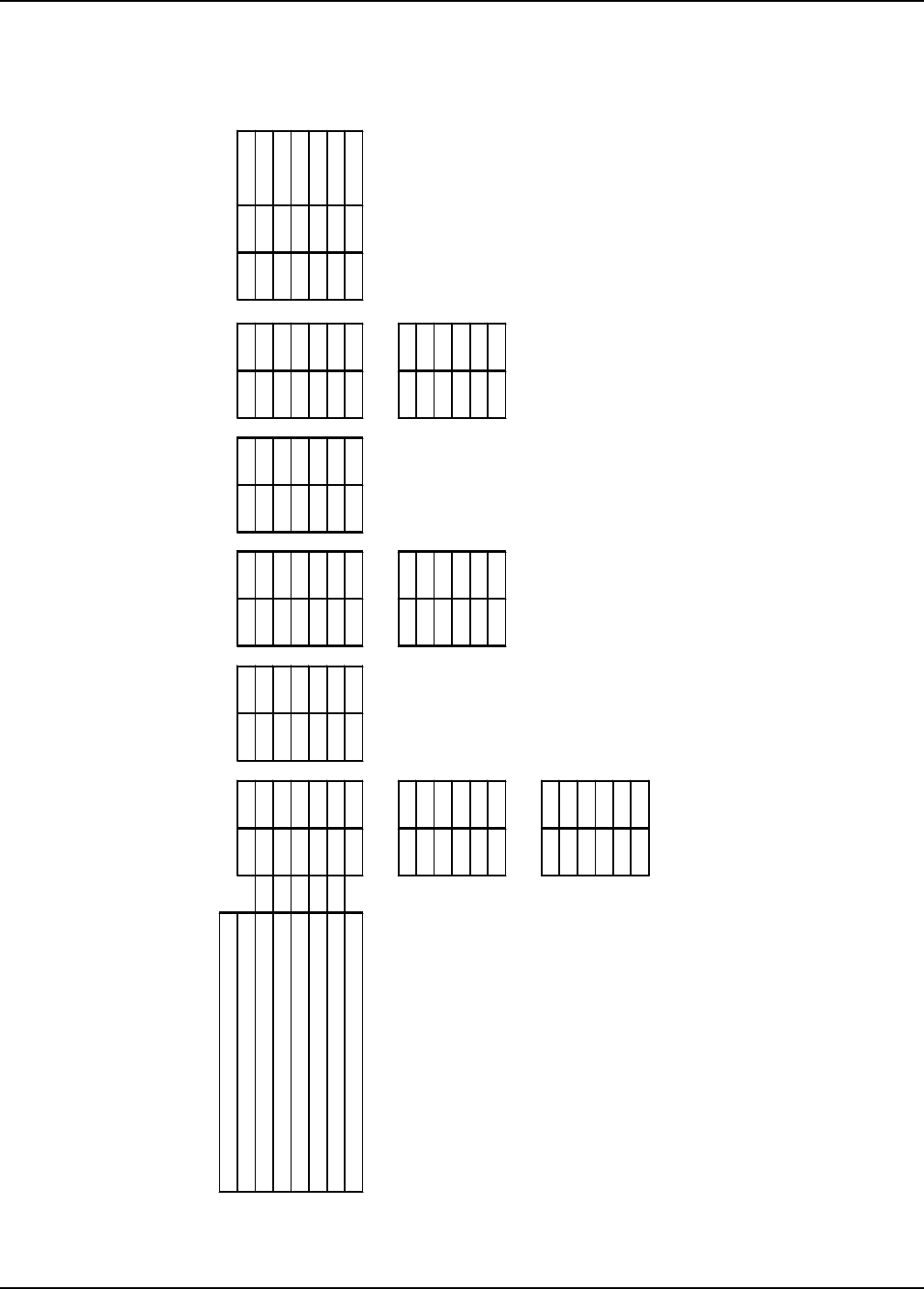
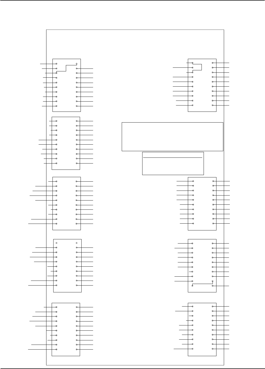
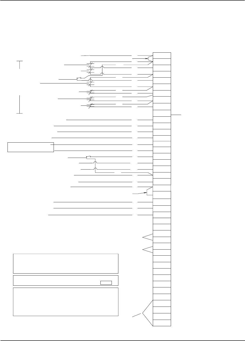
Input/Output Board Identification
1
3
5
7
9
2
4
6
8
10
12
14
16
18
20
11
13
15
17
19
J1
1
3
5
7
9
2
4
6
8
10
12
14
16
18
20
11
13
15
17
19
J2
1
3
5
7
9
2
4
6
8
10
12
14
16
18
20
11
13
15
17
19
J3
1
3
5
7
9
2
4
6
8
10
12
14
16
18
20
11
13
15
17
19
J4
1
3
5
7
9
2
4
6
8
10
12
14
16
18
20
11
13
15
17
19
J5
20
18
16
14
12
19
17
15
13
11
9
7
5
3
1
10
8
6
4
2
J6
20
18
16
14
12
19
17
15
13
11
9
7
5
3
1
10
8
6
4
2
J7
20
18
16
14
12
19
17
15
13
11
9
7
5
3
1
10
8
6
4
2
J8
20
18
16
14
12
19
17
15
13
11
9
7
5
3
1
10
8
6
4
2
J9
FAN #1 ON
FAN #1 AUTO
FAN #1 VAPOR HIGH LIMIT
FAN #1 HOUSING HIGH LIMIT
FAN #1 FLAME DETECTION
FAN #1 PLENUM
BURNER #1 ON
FAN #1 AIR
BURNER #1 AUTO
LOWER GRAIN HIGH LIMIT
FAN #2 ON
FAN #2 AUTO
FAN #2 VAPOR HIGH LIMIT
FAN #2 HOUSING HIGH LIMIT
FAN #2 FLAME DETECTION
FAN #2 PLENUM
FAN #2 AIR
BURNER #2 ON
BURNER #2 AUTO
FAN #3 ON
FAN #3 AUTO
FAN #3 VAPOR HIGH LIMIT
FAN #3 HOUSING HIGH LIMIT
FAN #3 FLAME DETECTION
FAN #3 PLENUM
BURNER #3 ON
FAN #3 AIR
BURNER #3 AUTO
FAN #4 ON
FAN #4 AUTO
FAN #4 VAPOR HIGH LIMIT
FAN #4 HOUSING HIGH LIMIT
FAN #4 FLAME DETECTION
FAN #4 PLENUM
FAN #4 AIR
BURNER #4 ON
BURNER #4 AUTO
FAN #5 ON
FAN #5 AUTO
FAN #5 VAPOR HIGH LIMIT
FAN #5 HOUSING HIGH LIMIT
FAN #5 FLAME DETECTION
FAN #5 PLENUM
BURNER #5 ON
FAN #5 AIR
BURNER #5 AUTO
FAN #6 ON
FAN #6 AUTO
FAN #6 VAPOR HIGH LIMIT
FAN #6 HOUSING HIGH LIMIT
FAN #6 FLAME DETECTION
FAN #6 PLENUM
FAN #6 AIR
BURNER #6 ON
BURNER #6 AUTO
CONTINUOUS FLOW
BATCH MODE
LOAD SWITCH ON
LOAD SWITCH AUTO
1 SPEED UNLOAD
UNLOAD BYPASS
2 SPEED UNLOAD
FIXED GRAIN (UPPER)
FIXED GRAIN (MIDDLE)
ADJ. GRAIN (UPPER)
ADJ. GRAIN (MIDDLE)
LOWER ADJ. GRAIN HIGH LIMIT
M.C. THERMOATAT N.C. TERM #6
M.C. THERMOSTAT N.O. TERM #4
REAR DISCHARGE
12 VOLT DC NEGATIVE
12 VOLT DC NEGATIVE
12 VOLT DC NEGATIVE
+12 LIMIT OUTPUT
MAXON VALVE SENSOR
OUT OF GRAIN SENSOR
MOTOR OVERLOADS
SAFETY CIRCUIT INPUT
12 VOLT DC NEGATIVE
12 VOLT DC NEGATIVE
METERING ROLL INPUT
12 VOLT DC NEUTRAL
+12 VOLT LIMIT OUTPUT
+12 LIMIT OUTPUT
M.R.H POT 3
NC
HI-HEAT POWER (BO)
LO-HEAT POWER (BO)
AC NEUTRAL
BURNER #2 NEUTRAL
MAXON NEUTRAL
BURNER #1 NEUTRAL
PROCESS LIGHT
NC
NC
THERMOSTAT 110VAC (BO)
FAN #5 NEUTRAL
FAN #6 NEUTRAL
BUR #5 NEUTRAL
BUR #6 NEUTRAL
MAXON POWER
LOAD #2 POWER
NC
NC
EMERGENCY COOLING
EMERGENCY COOLING
AUX #6 A-N.C.
THERMOSTAT SENSOR S2
SENSOR 1 LOWER
SENSOR 1 UPPER
SCR P3 & V1 FROM BR#2 (B
0
M.R.L POT 3 &
HIGH SOLENOID BUR#1 (BO)
NC
EMERGENCY COOLING
AUX #6 B-COMMON
ENERGENCY COOLING
SENSOR 2 UPPER
SENSOR 2 LOWER.
THERMOSTAT SENSOR S1
M.R.L POT 2 & HI SOLENOID BUR#2 (BO)
M.R.H POT 2
SCR P1 &
V1 FROM BR#1 (BO)
SCR NEUTRAL
UNLOAD NEUTRAL
FAN #2 NEUTRAL
FAN #1 NEUTRAL
SCR POWER
BURNER #6 POWER
LOAD POWER
BURNER #5 POWER
BURNER #4 POWER
FAN # 3 NEUTRAL
FAN # 4 NEUTRAL
BUR # 3 NEUTRAL
BUR # 4 NEUTRAL
UNLOAD POWER
FAN #6 POWER
FAN #5 POWER
FAN #4 POWER
FAN #3 POWER
LOAD #2 NEUTRAL
LOAD NEUTRAL
BURNER #3 POWER
BURNER #1 POWER
AC NEUTRAL
AC NEUTRAL
AC NEUTRAL
120VAC POWER (OUTPUT)
AC NEUTRAL
AC NEUTRAL
120VAC POWER (OUTPUT)
FAN #1 POWER
AC NEUTRAL
AC NEUTRAL
AC NEUTRAL
AC NEUTRAL
AC NEUTRAL
120VAC POWER (INPUT)
AC NEUTRAL
120VAC POWER (INPUT)
FAN #2 POWER
BURNER #2 POWER
+12 VOLT LIMIT OUTPUT
+12 VOLT LIMIT OUTPUT
FLAME SENSOR RETURN
120 VOLT AC OUTPUTS12 VOLT DC INPUTS
LOW MERCURY SWITCH (BO)
USER SUPPLIED SAFETY
MOISTURE CONTROL
MERCOID SFTY FAN#4 (CAN)
MERCOID SFTY FAN#2 (CAN)
MERCOID SFTY FAN#1 (CAN)
MERCOID SAFTY FAN#3 (CAN)
OUT OF GRAIN FOR LOAD #2
LO-HEAT THERMOSTAT (BO)HI-HEAT THERMOSTAT (BO)
JUMPER J1-9 TO J5-6 IS A HARDWARE TIMER FOR THE FLAME SENSOR SHUTDOWN
JUMPER J5-2 TO J5-20 IS A CONNECTION FOR THE MAXON VALVE SENS0R
JUMPER J4-12 TO J5-10 IS A HARDWARE TIMER FOR THE SAFETY SHUTDOWNS
JUMPERS MUST BE INSTALLED FOR THE INPUT/OUTPUT BOARD TO OPERATE!!
JUMPER J1-20 TO J5-8 IS A CONNECTION FOR THE USER SUPPLLIED SAFETY
JUMPERS TO BE INSTALLED FOR E-COOL
INSTALL JUMPER FROM J6-13 TO J1-5
INSTALL JUMPER FROM J6-14 TO J1-19
INSTALL JUMPER FROM J6-16 TO J5-5
INSTALL JUMPER FROM J6-17 TO J4-19
** IMPORTANT--JUMPERS LISTED ABOVE MUST BE INSTALLED
Portable Dryer Troubleshooting
13
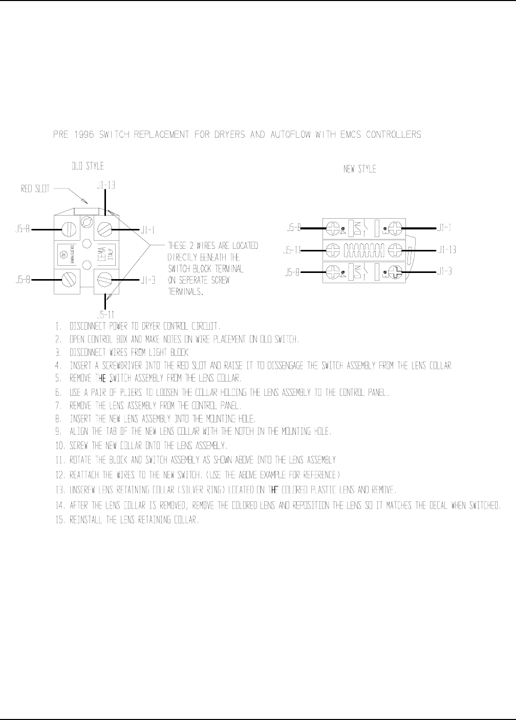
Switch Replacement for EMCS Dryer
Switch N/O Contact Block - Part No. D63-0006
Switch Light Block - D01-0455
Switch Replacement
Portable Dryer Troubleshooting
14
Wiring Reference
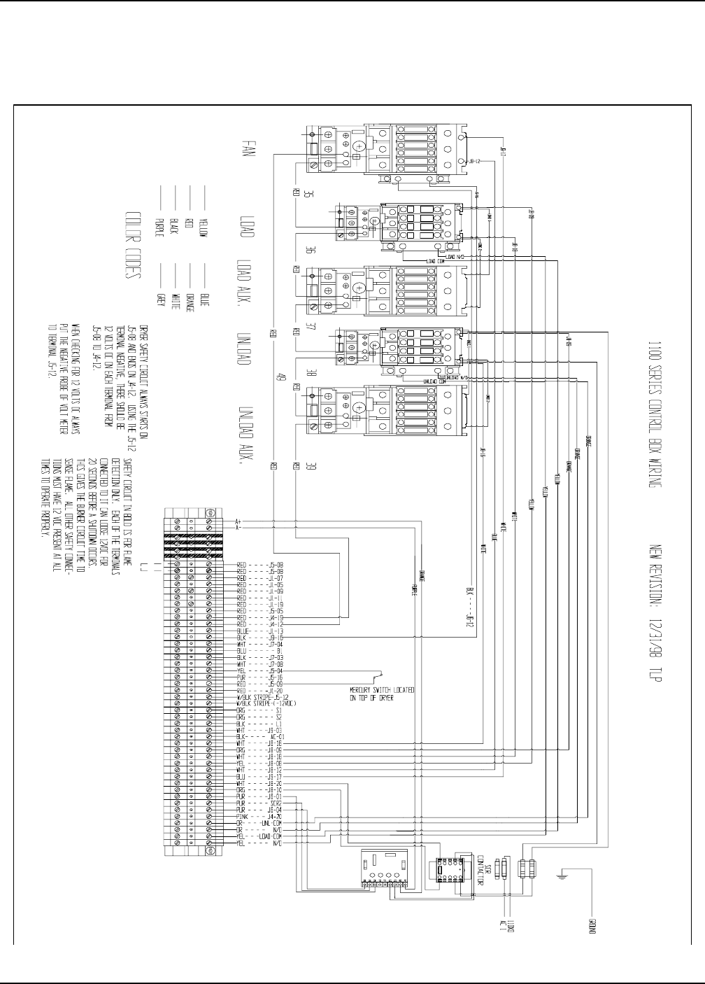
1100 Series Control Box Wiring
NEED JUMPER
NEED JUMPER
RED J5-8
120 VAC (BLACK)AC 1
120 VAC NEUT (WHITE)J9-3
USED ON SINGLE FAN
NAT GAS ONLY
SAFETY CIRCUIT
RELAY CONTACTS LOCATED
IN DRYER FAN CAN BOX
SAFETY CIRCUIT IN BOLD IS FOR FLAME DETECTION ONLY.
EACH OF THE TERMINALS CONNECTED TO IT CAN LOOSE
12 VDC FOR 20 SECONDS BEFORE A SHUTDOWN OCCURS.
THIS GIVES THE BURNER CIRCUIT TIME TO SENSE FLAME.
ALL OTHER SAFETY CONNECTIONS MUST HAVE 12 VDC
PRESENT AT ALL TIMES TO OPERATE PROPERLY.
WHEN CHECKING FOR 12 VOLTS DC ALWAYS PUT THE
NEGATIVE PROBE OF VOLT METER TO TERMINAL J5-12
DRYER SAFETY CIRCUIT ALWAYS STARTS ON J5-8 AND ENDS
ON J4-12.USING THE J5-12 TERMINAL FOR NEGATIVE,
THERE SHOULD BE 12 VOLTS DC ON EACH TERMINAL FROM
J5-8 TO J4-12.
MERCURY SWITCH LOCATED
ON TOP OF DRYER
AUX CONTACT POINTS FOR LOAD AND UNLOAD SYSTEMS
ALL VOLTAGE SUPPLIED BY USER LOAD AUX N/O (YELLOW)
L-N/O
LOAD AUX COM (YELLOW)
L-COM
UNLOAD AUX N/O(ORANGE)
U-N/O
UNLOAD AUX COM(ORANGE)
U-COM
*LOCATED AT REAR OF DRYER
*
*
COLORVOLTAGE
42 TOTAL TERMINALS
WIRINGDESCRIPTION
BRN
ALL SAFETIES MUST BE CLOSED FOR DRYER TO OPERATE
120VAC FOR AUX LOAD CONTACTOR COIL
120VAC FOR AUX UNLOAD CONTACTOR COIL
O
K OTHER SIDE
(
N/C
)
SAFETY
J
5-8 OR J5-9 --
12 VOLTS DC (RED)BLK
CUSTOMER SUPPLIED SAFETY
J1-20
SCR 2
120 VAC (BLUE)
120 VAC NEUT (WHITE)
J6-4
J6-1
J8-20
CONTROL POT P3 (PUR)
CONTROL POT P2 (PUR)
CONTROL POT P1 (PUR)
120 VAC (ORANGE)
120 VAC NEUT (WHITE)
120 VAC (YELLOW)
120 VAC NEUT (WHITE)
120 VAC (ORANGE)
120 VAC NEUT (WHITE)
J8-10
J9-17
J8-12
J8-8
J8-18
J8-9
J8-16
OR
RED
MOTOR OVERLOADS
TEMP SENSOR (ORANGE)
TEMP SENSOR (ORANGE)
12 VOLTS DC NEG (WHITE)
12 VOLTS DC (RED)
NO LONGER USED
METER ROLL PULSE (PUR)
12 VOLTS DC (YELLOW)
120 VAC NEUT (WHITE)
120 VAC (BLACK)
120 VAC (BLUE)
120 VAC NEUT (WHITE)
120 VAC (BLACK)
12 VOLTS DC (BLUE)
12 VOLTS DC (RED)
12 VOLTS DC (RED)
12 VOLTS DC (RED)
12 VOLTS DC (RED)
12 VOLTS DC (RED)
12 VOLTS DC (RED)
12 VOLTS DC (RED)
12 VOLTS DC (RED)
12 VOLTS DC (RED)
120 VAC (BLACK)
B1
L1
WORK LIGHT
J4-12
RED
RED
OR
OR
OR
BLU
BLK
YEL
BLK
WHT
BLK
RED
BLU
YEL
BLK
WHT
PUR
BLK
WHT
BRN
BLU
OR
PUR
YEL
RED
TEMP SENSORS
TEMP SENSORS
S2
S1
J7-3
BURNER LIGHT
J5-9
J5-12
J5-19
J5-16
RIGHT METERING ROLL SENSOR
METERING ROLL NEUTRAL
J5-4
J7-8
J7-4
J9-16
J1-13
J4-19
J5-5
J1-11
J1-19
J1-9
J1-5
J1-7
J5-8
METERING ROLL 12 VOLTS
LEFT METERING ROLL SENSOR
OUT OF GRAIN SENSOR
MAXON NEUTRAL
MAXON POWER
BURNER NEUTRAL
BURNER POWER
AIR PRESSURE SWITCH
RIGHT FIXED GRAIN HI LIMIT
PLENUM
*REAR DISCHARGE
LEFT FIXED GRAIN HI LIMIT
FLAME DETECTION
VAPOR HIGH LIMIT (LP ONLY)
HOUSING HIGH LIMIT
1100EW98.PRT REV. DATE 4/10/98
-12VDC
AIR PRESSURE SWITCH +12VDC
1100 FAN TO CONTROL BOX WIRING
Portable Dryer Troubleshooting
15
Wiring Reference
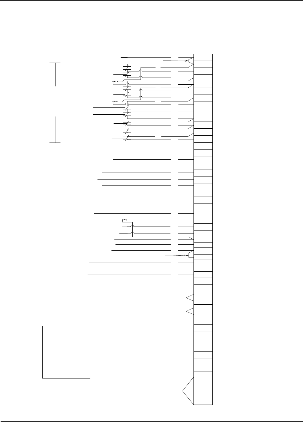
1100 Series Control Box Wiring (New Version)
Portable Dryer Troubleshooting
16
Wiring Reference
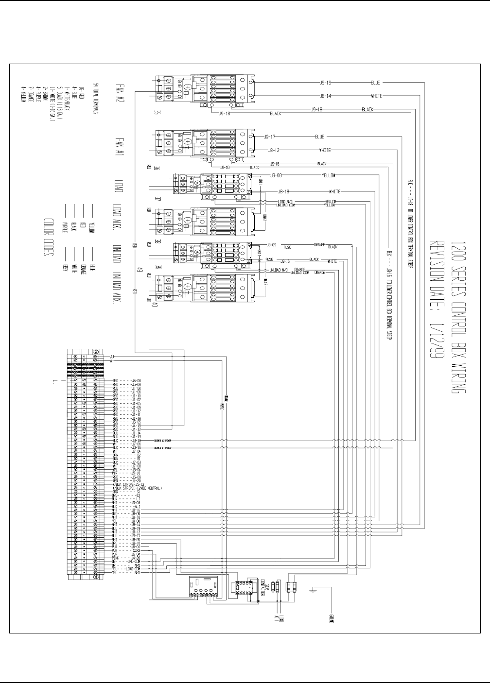
1200 Series Control Box Wiring
52 TOTAL TERMINALS
SAFETY CIRCUIT
NEED JUMPER
NEED JUMPER
RED
53 TOTAL TERMINALS
15 - RED
4 - BLUE
1 - WHITE/BLACK
3 - BLACK (1-16GA)
9 - WHITE (1-16GA
2 - BROWN
4 - PURPLE
4 - ORANGE)
-12VDC
AIR PRESSURE SWITCH +12VDC
1200EW98.PRT REV. DATE 3/5/98
HOOK OTHER SIDE
OF (N/C) SAFETY
TO J5-8 OR J5-9 --
J5-8
120 VAC (BLACK)AC 1
120 VAC NEUT (WHITE)
J9-3
RELAY CONTACTS LOCATED
IN FAN CAN CONTROL BOX
MERCURY SWITCH LOCATED
ON TOP OF DRYER
RELAY CONTACTS LOCATED
IN FAN CAN CONTROL BOX
AUX CONTACT POINTS FOR LOAD AND UNLOAD SYSTEMS
ALL VOLTAGE SUPPLIED BY USER
LOAD AUX N/O (YELLOW)
L-N/O
LOAD AUX COM (YELLOW)
L-COM
UNLOAD AUX N/O(ORANGE)
U-N/O
UNLOAD AUX COM(ORANGE)
U-COM
*LOCATED AT REAR OF DRYER
ALL SAFETIES MUST BE CLOSED FOR DRYER TO OPERATE
COLORVOLTAGE
TERMINAL
WIRING
DESCRIPTION
120VAC FOR AUX LOAD CONTACTOR COIL
120VAC FOR AUX UNLOAD CONTACTOR COIL
CUSTOMER SUPPLIED SAFETY RED 12 VOLTS DC (RED)
J1-20
SCR 2
J6-4
J6-1
J8-20
CONTROL POT P3 (PUR)
CONTROL POT P2 (PUR)
CONTROL POT P1 (PUR)
120 VAC (ORANGE)
120 VAC NEUT (WHITE)
120 VAC NEUT (WHITE)
120 VAC (BLUE)
120 VAC (BLUE)
120 VAC NEUT (WHITE)
120 VAC (YELLOW)
120 VAC NEUT (WHITE)
120 VAC (ORANGE)
120 VAC NEUT (WHITE)
J8-10
J9-17
J8-12
J9-19
J8-14
J8-8
J8-18
J8-9
J8-16
RED
OR
OR
MOTOR OVERLOADS
120 VAC (BLACK)
TEMP SENSOR (ORANGE)
TEMP SENSOR (ORANGE)
12 VOLTS DC NEG (WHITE)
12 VOLTS DC (RED)
NO LONGER USED
METER ROLL PULSE (PUR)
12 VOLTS DC (YELLOW)
120 VAC NEUT (WHITE)
120 VAC (BROWN)
120 VAC (BROWN)
120 VAC NEUT (WHITE)
120 VAC (BLACK)
120 VAC NEUT (WHITE)
120 VAC (BLACK)
12 VOLTS DC (BLUE)
12 VOLTS DC (BLUE)
12 VOLTS DC (RED)
12 VOLTS DC (RED)
12 VOLTS DC (RED)
12 VOLTS DC (RED)
12 VOLTS DC (RED)
12 VOLTS DC (RED)
12 VOLTS DC (RED)
12 VOLTS DC (RED)
12 VOLTS DC (RED)
12 VOLTS DC (RED)
12 VOLTS DC (RED)
12 VOLTS DC (RED)
12 VOLTS DC (RED)
120 VAC (BLACK)
B1
B2
L1 WORK LIGHT
J4-12
BLK
RED
RED OR
BRN
OR
RED BLU
YEL
RED
BLK
WHT
BLK
RED
BLU
YEL
BLK
WHT
PUR
BLK
WHT
BRN
BRN
WHT
BLK
BLU
BLU
RED
OR
PUR
YEL
OR
PUR
YEL
RED
TEMP SENSOR
TEMP SENSOR
S2
S1
J7-3
BURNER #1 LIGHT
BURNER #2 LIGHT
J5-9
J5-12
J5-19
J5-16
*RIGHT METERING ROLL SENSOR
METERING ROLL NEGATIVE
J5-4
J7-8
J7-4
J9-16
J7-6
J9-18
J1-13
J1-14
J4-19
J5-5
J1-11
J1-12
J1-19
J1-9
J1-5
J1-7
J1-10
J1-6
J1-8
J5-8
METERING ROLL 12 VOLTS
*LEFT METERING ROLL SENSOR
OUT OF GRAIN SENSOR
MAXON NEUTRAL
MAXON POWER
BURNER #1 NEUTRAL
BURNER #1 POWER
BURNER #2 NEUTRAL
BURNER #2 POWER
FAN #1 PRESSURE SWITCH
FAN #2 PRESSURE SWITCH
ADJ. GRAIN HIGH LIMIT
FAN #2 PLENUM
FAN #1 PLENUM
*REAR DISCHARGE
FIXED GRAIN HIGH LIMIT
FAN #1 FLAME DETECTION
FAN #1 VAPOR HIGH LIMIT
FAN #1 HOUSING HIGH LIMIT
FAN #2 FLAME DETECTION
FAN #2 VAPOR HIGH LIMIT
FAN #2 HOUSING HIGH LIMIT
Portable Dryer Troubleshooting
17
Wiring Reference
1200 Series Control Box Wiring (New Version)
Portable Dryer Troubleshooting
18
J8-16 WHITE - AC NEUTRAL - UNLOAD NEUTRAL
35 - D01-0531 ENTRELEC TERMINALS
2 - D01-0533 END STOPS
1 - D01-0532 BLANK PROTECTOR END
J9-17 BLUE - 120 VAC - FAN #1 POWER
EMERGENCY COOLING JUMPERS
INSTALL J6-13 TO J1-5
INSTALL J6-14 TO J1-19
INSTALL J6-16 TO J5-5
INSTALL J6-17 TO J4-19
INSTALL J1-9 TO J5-6
INSTALL J5-2 TO J5-20
INSTALL J4-12 TO J5-10
INSTALL J1-20 TO J5-8
I/O BOARD JUMPERS
RED - 12 VDC - LOWER ADJUSTABLE GRAIN HIGH LIMIT
RED - 12 VDC - MOTOR OVERLOADS
RED - 12 VDC - USER SUPPLIED SAFETY
RED - 12 VDC - LOWER FIXED GRAIN LIMIT
BLUE - 12 VDC - FAN #1 AIR SWITCH
RED - 12 VDC - FAN #1 PLENUM HIGHT LIMIT
RED - 12 VDC - FAN #1 FLAME DETECTION
RED - 12 VDC - FAN #1 HOUSING HIGH LIMIT
BLACK - 120 VAC - BURNER #1 POWER
WHITE - AC NEUTRAL - SCR NEUTRAL
WHITE - AC NEUTRAL - LOAD NEUTRAL
WHITE - AC NEUTRAL - FAN #1 NEUTRAL
ORANGE - 120 VAC - SCR POWER
ORANGE - 120 VAC - UNLOAD POWER
YELLOW - 120 VAC - LOAD POWER
WHITE - AC NEUTRAL - MAXON NEUTRAL
WHITE - AC NEUTRAL - BURNER NEUTRAL
BLACK - 120 VAC - MAXON POWER
PURPLE - CONTROL POT P3
PURPLE - CONTROL POT P1
PURPLE -TIMING PULSE- RIGHT METERING ROLL PULSE
PURPLE -TIMING PULSE- LEFT METERING ROLL PULSE
WHITE - 12 VDC NEG - 12 VOLT SUPPLY NEGATIVE
RED - 12 VDC - 12 VOLT SUPPLY
RED - 12 VDC - 12 VOLT SUPPLY
RED - 12 VDC - REAR DISCHARGE SWITCH
YELLOW - 12 VDC - OUT OF GRAIN SENSOR
RED - 12 VDC - FAN #1 VAPOR HIGH LIMIT
PURPLE - CONTROL POT P2
ORANGE - TEMPERATURE SENSOR
ORANGE - TEMPERATURE SENSOR
BROWN - 120 VAC - BURNER #1 LIGHT
BLACK - 120 VAC - OUTSIDE LIGHT
S2
J9-16
J8-20
J8-18
J8-12
J8-10
J8-9
J8-8
J7-8
J7-4
J7-3
J6-4
J6-1
J5-19
J5-16
J5-12
J5-9
J5-8
J5-5
J5-4
J4-19
J4-12
J1-20
J1-19
J1-13
J1-11
J1-9
J1-7
J1-5
SCR2
S1
B1
L1
J9-3
AC-1
J9-3
J9-1
EMI FILTER
D03-0181
LOAD
LINE
5VB1
1100 Fan Lower Control Box Interconnect Strip
Wiring Reference
Portable Dryer Troubleshooting
19
1200 Fan Lower Control Box Interconnect Strip
S2 ORANGE - TEMPERATURE SENSOR
S1 ORANGE - TEMPERATURE SENSOR
B2
WHITE - AC NEUTRAL - UNLOAD NEUTRALJ8-16
45 - D01-0531 ENTRELEC TERMINALS
2 - D01-0533 END STOPS
1 - D01-0532 BLANK PROTECTOR ENDS
BLUE - 120 VAC - FAN #2 POWERJ9-19
WHITE - AC NEUTRAL - FAN #2 NEUTRALJ8-14
WHITE - AC NEUTRAL - BURNER #2 NEUTRALJ7-6
BLUE - 12 VDC - FAN #2 AIR SWITCH
RED - 12 VDC - FAN #2 PLENUM HIGHT LIMIT
RED - 12 VDC - FAN #2 FLAME DETECTION
RED - 12 VDC - FAN #2 HOUSING HIGH LIMIT
RED - 12 VDC - FAN #2 VAPOR HIGH LIMIT
J1-14
J1-12
J1-10
J1-8
J1-6
BLACK - 120 VAC - BURNER #2 POWERJ9-18
BLUE - 120 VAC - FAN #1 POWERJ9-17
BROWN - 120 VAC - BURNER #2 LIGHT
EMERGENCY COOLING JUMPERS
INSTALL J6-13 TO J1-5
INSTALL J6-14 TO J1-19
INSTALL J6-16 TO J5-5
INSTALL J6-17 TO J4-19
INSTALL J1-9 TO J5-6
INSTALL J5-2 TO J5-20
INSTALL J4-12 TO J5-10
INSTALL J9-1 TO J9-5
I/O BOARD JUMPERS
RED - 12 VDC - LOWER ADJUSTABLE GRAIN HIGH LIMIT
RED - 12 VDC - MOTOR OVERLOADS
RED - 12 VDC - USER SUPPLIED SAFETY
RED - 12 VDC - LOWER FIXED GRAIN LIMIT
BLUE - 12 VDC - FAN #1 AIR SWITCH
RED - 12 VDC - FAN #1 PLENUM HIGHT LIMIT
RED - 12 VDC - FAN #1 FLAME DETECTION
RED - 12 VDC - FAN #1 HOUSING HIGH LIMIT
BLACK - 120 VAC - BURNER #1 POWER
WHITE - AC NEUTRAL - SCR NEUTRAL
WHITE - AC NEUTRAL - LOAD NEUTRAL
WHITE - AC NEUTRAL - FAN #1 NEUTRAL
ORANGE - 120 VAC - SCR POWER
ORANGE - 120 VAC - UNLOAD POWER
YELLOW - 120 VAC - LOAD POWER
WHITE - AC NEUTRAL - MAXON NEUTRAL
WHITE - AC NEUTRAL - BURNER #1 NEUTRAL
BLACK - 120 VAC - MAXON POWER
PURPLE - CONTROL POT P3
PURPLE - CONTROL POT P1
PURPLE -TIMING PULSE- RIGHT METERING ROLL PULSE
PURPLE -TIMING PULSE- LEFT METERING ROLL PULSE
WHITE - 12 VDC NEG - 12 VOLT SUPPLY NEGATIVE
RED - 12 VDC - 12 VOLT SUPPLY
RED - 12 VDC - 12 VOLT SUPPLY
RED - 12 VDC - REAR DISCHARGE SWITCH
YELLOW - 12 VDC - OUT OF GRAIN SENSOR
RED - 12 VDC - FAN #1 VAPOR HIGH LIMIT
PURPLE - CONTROL POT P2
BROWN - 120 VAC - BURNER #1 LIGHT
BLACK - 120 VAC - OUTSIDE LIGHT
J9-16
J8-20
J8-18
J8-12
J8-10
J8-9
J8-8
J7-8
J7-4
J7-3
J6-4
J6-1
J5-19
J5-16
J5-12
J5-9
J5-8
J5-5
J5-4
J4-19
J4-12
J1-20
J1-19
J1-13
J1-11
J1-9
J1-7
J1-5
SCR2
B1
L1
J9-3
AC-1
J9-3
J9-1
EMI FILTER
D03-0181
LOAD
LINE
5VB1
Wiring Reference
Portable Dryer Troubleshooting
20
YELLOW FROM J1-05 TO PLENUM HIGH LIMIT SWITCH
WHITE TO S1 FROM GRAIN TEMPERATURE SENSOR
BLACK TO S2 FROM GRAIN TEMPERATURE SENSOR
BLUE TO J1-11 FROM PLENUM HIGH LIMIT SWITCH
YELLOW FROM J1-05 TO PLENUM HIGH LIMIT SWITCH
ORANGE TO J4-19 FROM RIGHT GRAIN HIGH LIMIT SWITCH
RED FROM J5-05 TO RIGHT GRAIN HIGH LIMIT SWITCH
BLACK FROM J5-09 TO LOAD MERCURY SWITCH
BLACK TO J5-04 FROM LOAD MERCURY SWITCH
WHITE FROM J9-03 TO OUTSIDE LIGHT AC NEUTRAL
RED FROM L1 120VAC TO OUTSIDE LIGHT POWER
WHITE TO S1 FROM RIGHT GRAIN TEMPERATURE SENSOR
BLACK TO S2 FROM RIGHT GRAIN TEMPERATURE SENSOR
RED FROM J1-11 TO LEFT GRAIN HIGH LIMIT SWITCH
ORANGE TO J1-19 FROM LEFT GRAIN HIGH LIMIT SWITCH
PURPLE J7-03 MAXON POWER 120VAC (NATURAL GAS ONLY)
WHITE J7-08 MAXON 120VAC NEUTRAL (NATURAL GAS ONLY)
BROWN FROM J1-19 TO REAR DISCHARGE SWITCH
ORANGE TO J5-05 FROM REAR DISCHARGE SWITCH
RED 16 GA. A+ SCR DRIVE MOTOR
BLACK 16 GA. A- SCR DRIVE MOTOR
GREEN 16 GA. SCR DRIVE MOTOR GROUND
BLUE FROM J5-08 TO AIRSWITCH COMMON TERMINAL
BLUE TO J1-13 FROM AIRSWITCH N.O. TERMINAL
ORANGE FROM J5-08 TO FLAME DETECTION RELAYS
ORANGE FROM J1-09 TO FLAME DETECTION RELAYS
BLACK FROM J9-16 TO L1 ON FENWAL BOARD 120VAC POWER
WHITE FROM J7-04 TO L2 ON FENWAL BOARD 120VAC NEUTRAL
BROWN TO B1 FROM V1 ON FENWAL BOARD 120VAC
YELLOW TO J1-07 FROM HOUSING HIGH LIMIT SWITCH
RED FROM J5-08 TO HOUSING & VAPOR HIGH LIMIT SWITCHES
PURPLE TO J1-05 FROM VAPOR HIGH LIMIT SWITCH
WHITE/BLACK STRIP J5-12 12VDC NEGATIVE
TO PLENUM AND RIGHT
FIXED GRAIN HIGH LIMIT
SWITCHES AND TEMPERATURE
SENSORS
TO UPPER JUNCTION BOX
TO LOWER JUNCTION BOX
TO AIRSWITCH ASSEMBLY
TO FAN CONTROL BOX
Upper Control Box External Wiring
Wiring Reference
Portable Dryer Troubleshooting
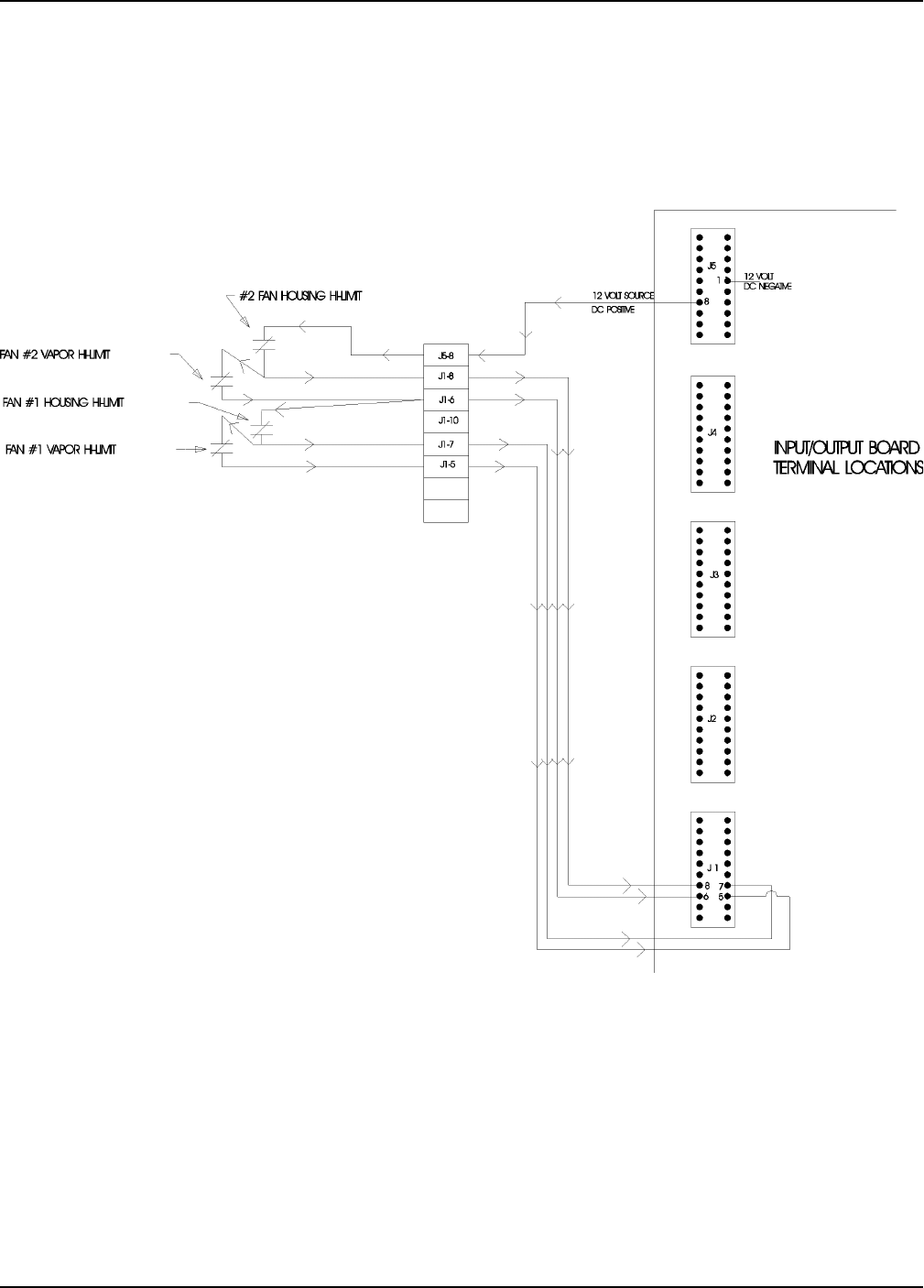
21
Fan Housing and Vapor Hi-Limit Circuit
Wiring Reference
Portable Dryer Troubleshooting
22
Plenum Hi-Temperature Switch
Wiring Reference
Portable Dryer Troubleshooting
23
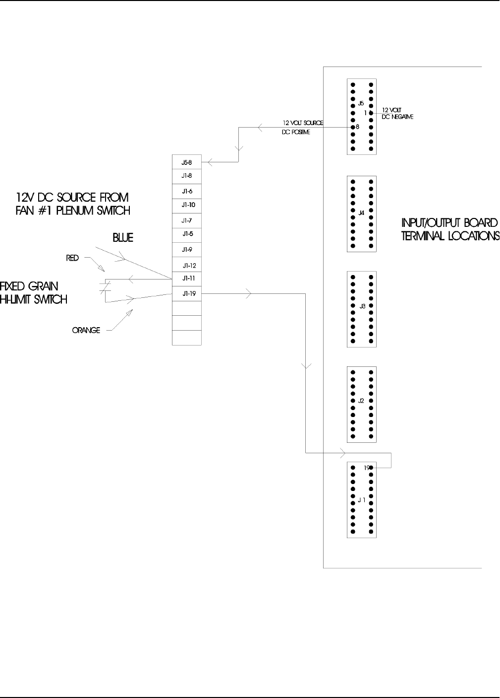
Fixed Grain Hi-Limit
Wiring Reference
Portable Dryer Troubleshooting
24
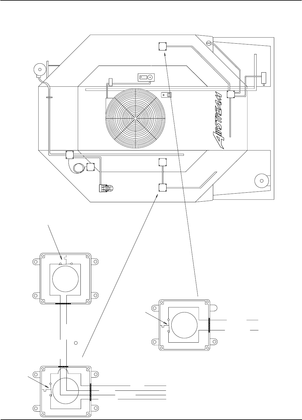
Grain & Plenum Hi-Limit Locations
PLENUM
SCR
UNLOAD
MOTOR
11XX
RIGHT FIXED
GRAIN HIGH
LIMIT
OUTSIDE LIGHT
TEMP. SENSORS
LOAD
MOTOR
LOAD MERCURY SWITCH
UPPER
BOX
JUNCTION
FAN
SOLENOID
BURNER
HI-LOW
THERMO
AIR SWITCH
LEFT FIXED
GRAIN HIGH
LIMIT
TEMP. SENSORS
GAS PIPE TRAIN
LOWER
BOX
JUNCTION
TO LOWER JUNCTION BOX
TO UPPER CONTROL BOX
YELLOW J1-05
BLUE J1-11
PLENUM HIGH LIMIT SWITCH
D03-0004 300 DEGREE
BLUE J1-11
YELLOW J1-05
RED J5-05
ORANGE J4-19
ORANGE J1-19
RED J1-11
RIGHT GRAIN HIGH LIMIT SWITCH
D03-0005 210 DEGREE
LEFT GRAIN HIGH LIMIT SWITCH
D03-0005 210 DEGREE
Wiring Reference
Portable Dryer Troubleshooting
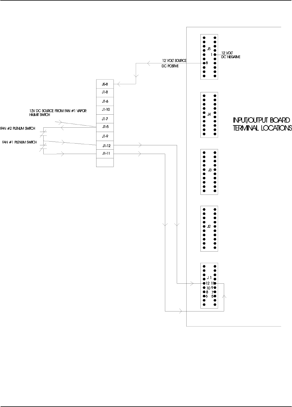
25
2FNLMTSW98.PRT REV. DATE 4/5/98
RED TO J1-05
BLUE TO J1-11
YELLOW TO J1-12
FAN #1
PLENUM HIGH LIMIT SWITCH
D03-0004 300 DEGREE
FIXED GRAIN HIGH LIMIT SWITCH
D03-0005 210 DEGREE
RED TO J1-11
ORANGE TO J1-19
FAN #2
PLENUM HIGH LIMIT SWITCH
D03-0004 300 DEGREE
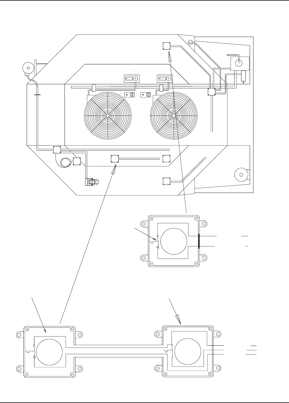
TO LOWER JUNCTION BOX
JUNCTION
BOX
UPPER
LOAD MERCURY SWITCH
MOTOR
LOAD
FIXED GRAIN
AIR
SWITCHES
TEMP. SENSORS
OUTSIDE LIGHT
LIMIT
GRAIN HIGH
ADJUSTABLE
THERMO SENSORS
HI-LIMIT AND
THERMO
HI-LOW
BURNER #1
THERMO
HI-LOW
BURNER #2
PLENUM #2
SOLENOID
FAN #2
SOLENOID
12XX
MOTOR
UNLOAD
SCR
FAN #1
MAXON
PLENUM #1
Two Fan Plenum and Grain Limit Switch Wiring
Wiring Reference
Portable Dryer Troubleshooting
26
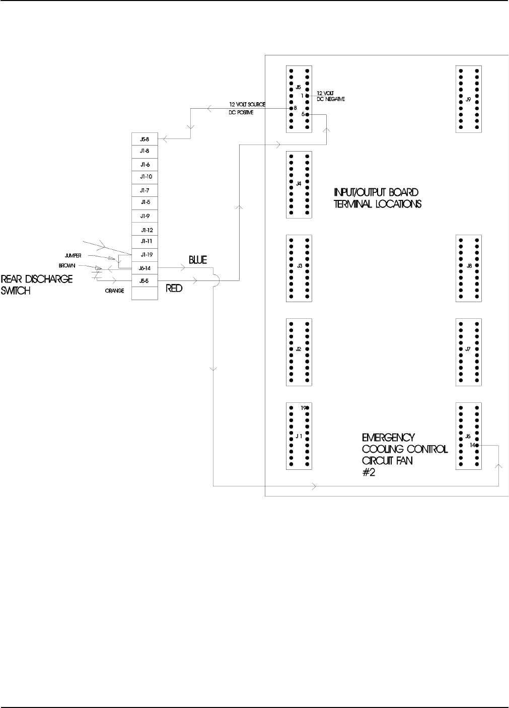
Rear Discharge & Emergency Cooling Circuit
Wiring Reference
Portable Dryer Troubleshooting
27
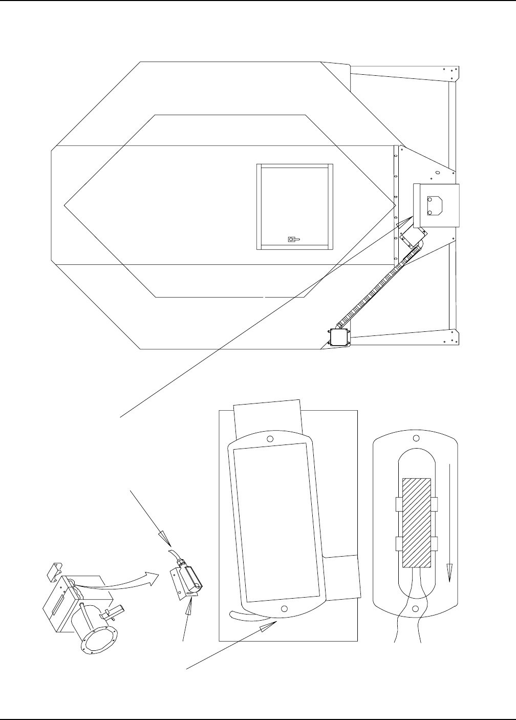
Rear Discharge Mercury Switch
POSITIONED WITH LID CLOSED AND
SJOW 18/2 CORD POINTED TOWARDS
THE FRONT OF THE DRYER CONNECT
INSIDE METER ROLL BOX TO BROWN
AND ORANGE WIRES.
CONNECT TO SJOW CORD
INSIDE LRL BOX
LOOSEN SCREWS ON BRACKET
TO CHANGE SENSITIVITY
OF REAR DISCHARGE SWITCH
Wiring Reference
Portable Dryer Troubleshooting
28
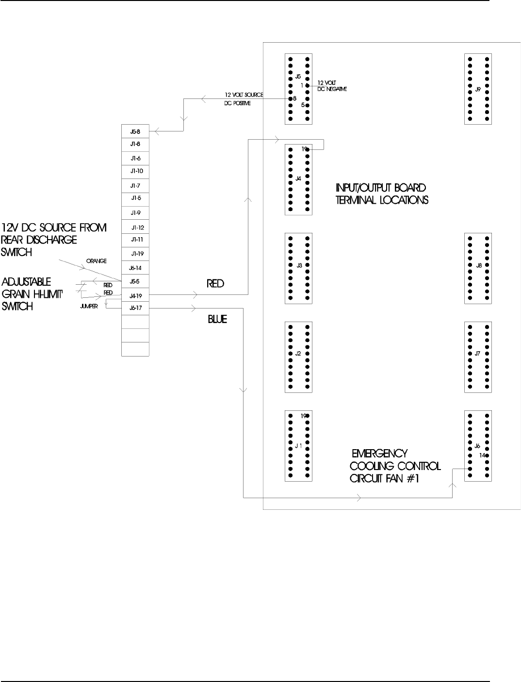
Adjustable Hi-Limit & Emergency Cooling Circuit
Wiring Reference
Portable Dryer Troubleshooting
29
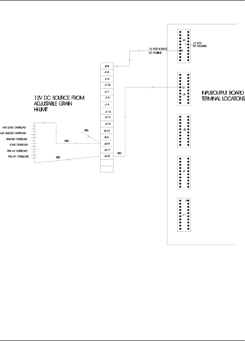
Motor Overloads
Wiring Reference
Portable Dryer Troubleshooting
30
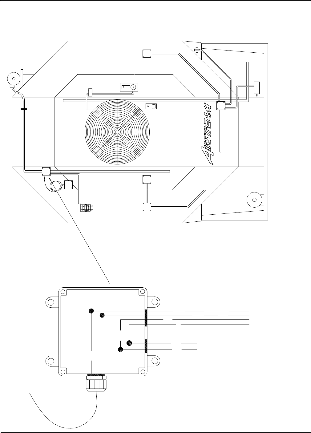
Air Pressure Switch
J5-8
J1-8
J1-6
J1-7
J1-5
8
J5
1 1 12 VOLT
DC NEGATIVE
12 VOLT SOURCE
DC POSITIVE
J2
J3
INPUT/OUTPUT BOAR
D
TERMINAL LOCATION
S
J1-10
J1-9
J1-12
J1-11
J1-19
J 1
J6-14
J5-5
J4-19
J6-17
J4-12
J4
12
J1-14
J1-13
14
12V DC SOURCE FROM
MOTOR OVERLOADS
FAN #2 PRESSURE SWITCH
FAN #1 PRESSURE SWITCH
13
PRESSURE SWITCH SAFETY
CIRCUIT
BLUE
BLUE
BLUE
BLUE
Wiring Reference
Portable Dryer Troubleshooting
31
HIGH
BACKVIEW OF AIR SWITCH ASSEMBLY
TO UPPER CONTROL BOX
BLUE J1-13 AIRFLOW (N.O.)
BLUE J5-08 12VDC POSITIVE
CALIBRATED WITH
DIAPHRAGM VERTICAL
C N.C. N.O.
JUNCTION
BOX
LOWER
GAS PIPE TRAIN
TEMP. SENSORS
LIMIT
GRAIN HIGH
LEFT FIXED
AIR SWITCH
SOLENOID
FAN
JUNCTION
BOX
UPPER
LOAD MERCURY SWITCH
MOTOR
LOAD
TEMP. SENSORS
OUTSIDE LIGHT
LIMIT
GRAIN HIGH
RIGHT FIXED
11XX
MOTOR
UNLOAD
SCR
PLENUM
Air Pressure Switch Drawing
Wiring Reference
Portable Dryer Troubleshooting
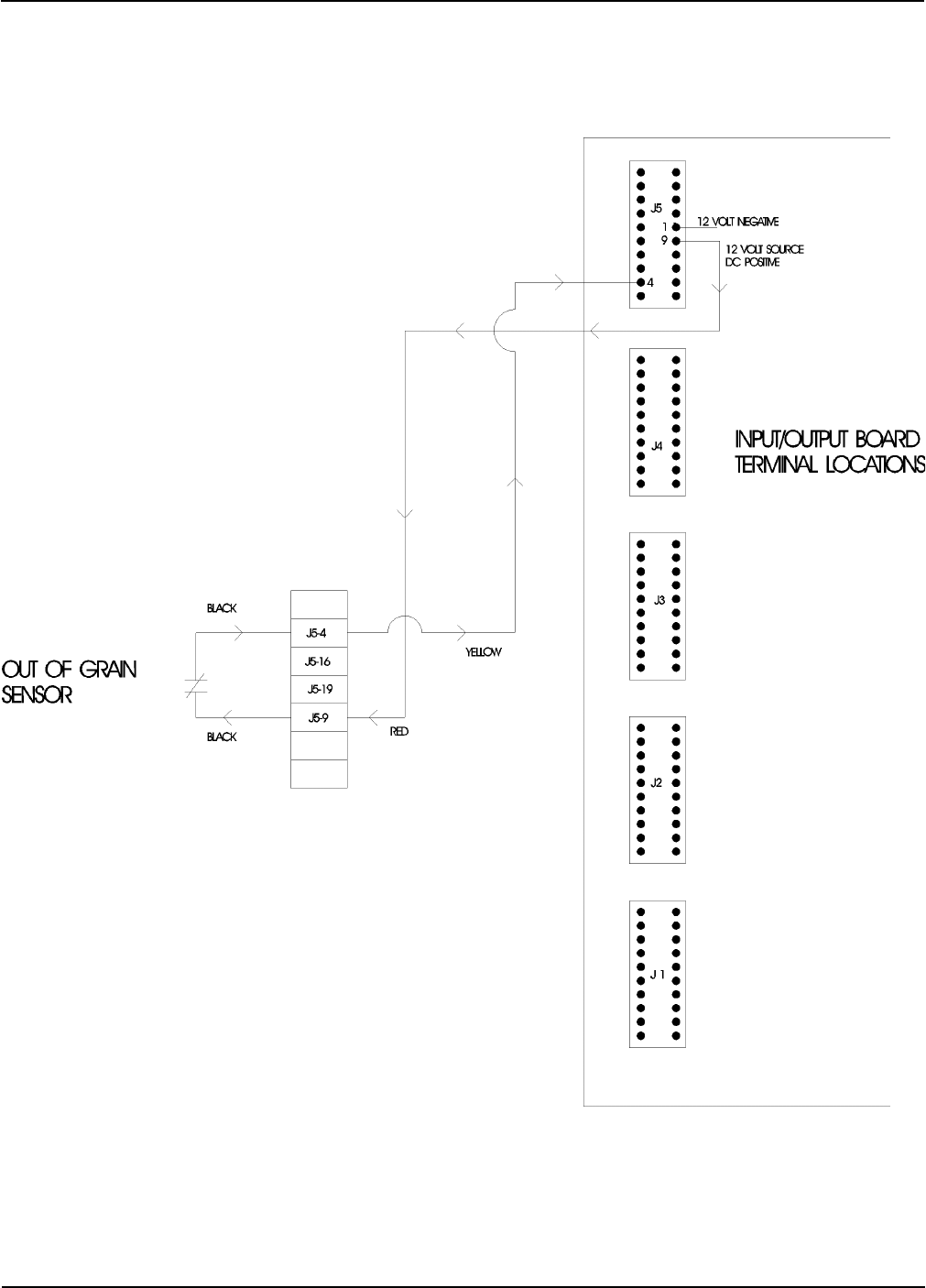
32
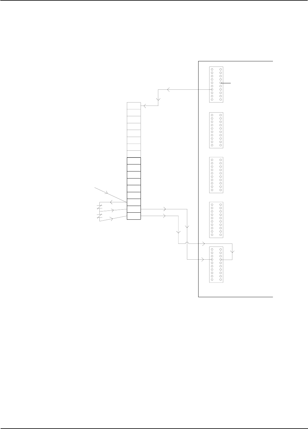
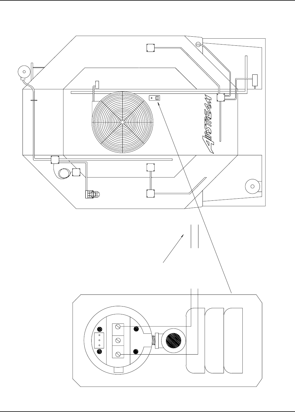
Out of Grain Safety Circuit
Wiring Reference
Portable Dryer Troubleshooting
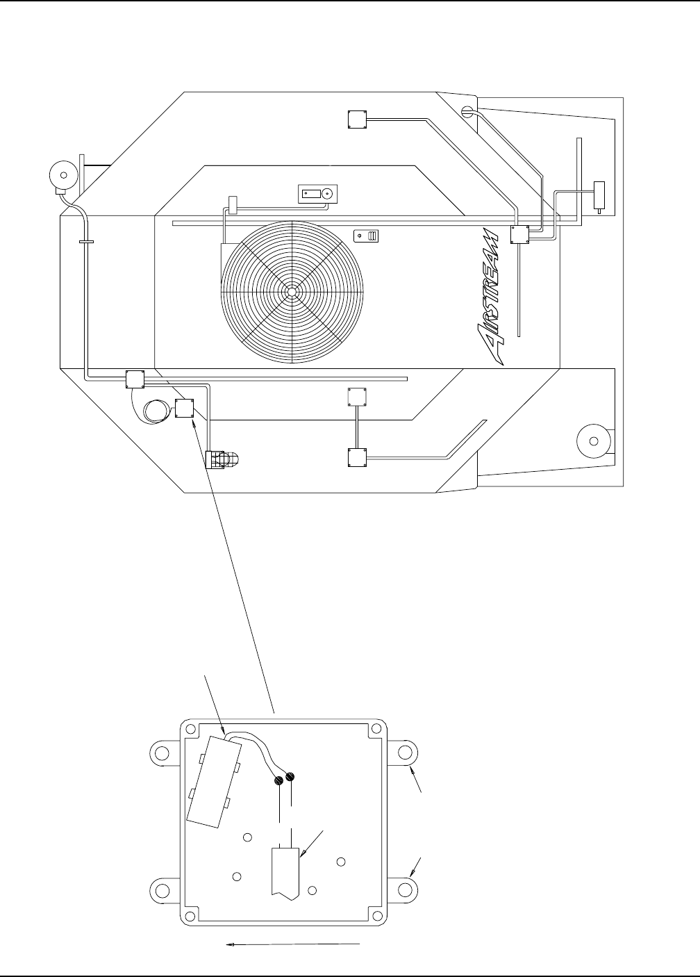
33
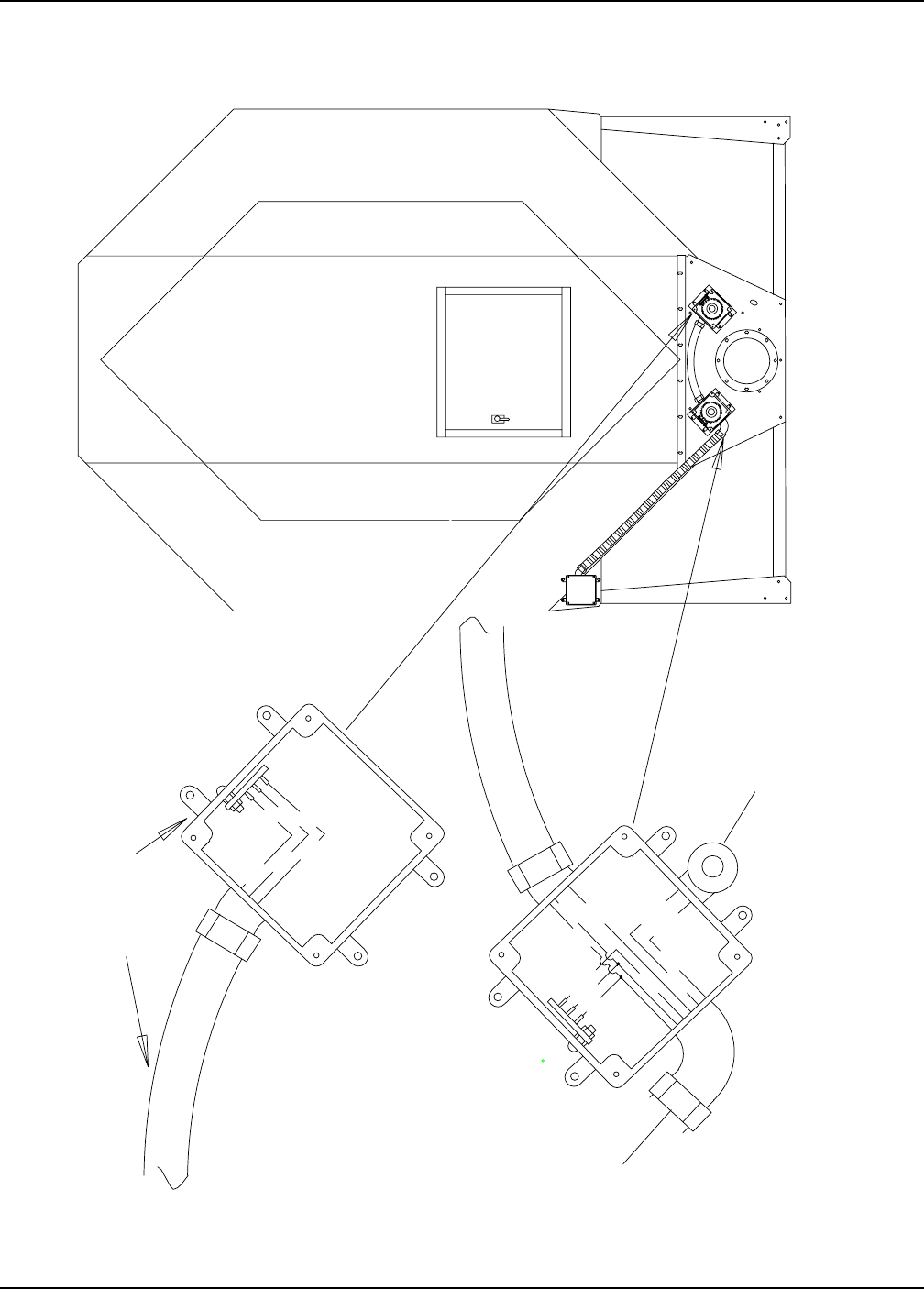
Out of Grain Safety Circuit Location
JUNCTION
BOX
LOWER
GAS PIPE TRAIN
TEMP. SENSORS
LIMIT
GRAIN HIGH
LEFT FIXED
AIR SWITCH
THERMO
HI-LOW
BURNER
SOLENOID
FAN
JUNCTION
BOX
UPPER
LOAD MERCURY SWITCH
MOTOR
LOAD
TEMP. SENSORS
OUTSIDE LIGHT
LIMIT
GRAIN HIGH
RIGHT FIXED
11XX
MOTOR
UNLOAD
SCR
PLENUM
REMOVE THESE EARS
SJOW 18/2 WIRE
EXITS THROUGH
BOX COVER
BLACK
WHITE
LEADS MUST BE IN THIS POSITION
FOR PROPER OPERATION
UP
FRONT VIEW OF OPEN BOX
Wiring Reference
Portable Dryer Troubleshooting
34
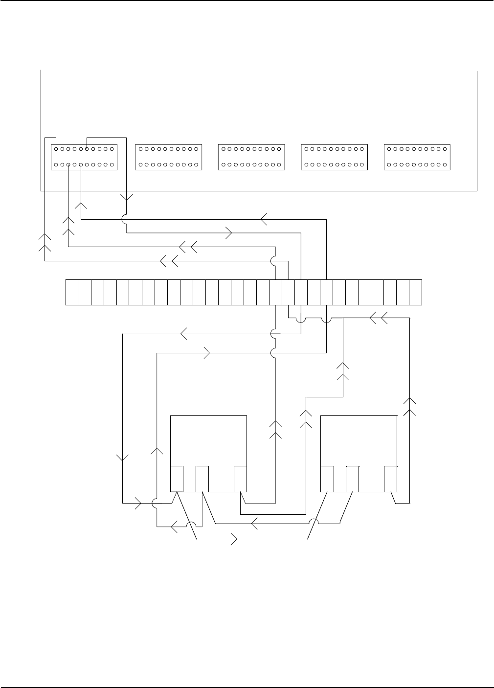
Upper Junction Box Drawing
RED
WHITE
TO OUTSIDE LIGHT FIXTURE
BLACK BLACK J5-04
TO 12VDC J5-09
J9-03
L1
TO LOAD MERCURY SWITCH
WHITE
BLACK
BLACK
WHITE
TO UPPER CONTROL BOX
PLENUM
SCR
UNLOAD
MOTOR
11XX
RIGHT FIXED
GRAIN HIGH
LIMIT
OUTSIDE LIGHT
TEMP. SENSORS
LOAD
MOTOR
LOAD MERCURY SWITCH
UPPER
BOX
JUNCTION
FAN
SOLENOID
BURNER
HI-LOW
THERMO
AIR SWITCH
LEFT FIXED
GRAIN HIGH
LIMIT
TEMP. SENSORS
GAS PIPE TRAIN
LOWER
BOX
JUNCTION
Wiring Reference
Portable Dryer Troubleshooting
35
Meter Roll Sensor
J5-09 J5-12
J5-19
J5-16
J5-05 J1-19
TO REAR DISCHARGE SWITCH
TO REAR
JUNCTION BOX
LEFT METER
ROLL SENSOR
RIGHT METER
ROLL SENSOR
J5-09 J5-12 J5-19
RED 12VDC POS
BLACK OR WHITE/BLACK STRIP 12VDC NEG
YELLOW LEFT METER PULSE RETURN
BLUE RIGHT METER PULSE RETURN
ORANGE REAR DISCHARGE RETURN
BROWN 12VDC TO DISCHARGE SWITCH
ORANGE
BROWN
YELLOW
BLACK
RED
RED
BLACK
BLUE
NOTE:
RIGHT SENSOR IS
NO LONGER USED ON
DRYERS MANUFACTURED
AFTER MARCH 1, 1997
Wiring Reference
Portable Dryer Troubleshooting
36
Meter Roll Sensor Wiring
1997 Dryers have only 1 meter roll board.
Remove one meter roll board and tie the
2 T-3 wires together.
Board
Meter Roll
Board
Meter Roll
12 Volt +
12 Volt -
12 Volt -
12 Volt +
Pulse
Pulse
T-2
T-1
T-3
T-2
T-1
T-3
METER ROLL SENSOR
J5-5
S2
S1
J5-12
J1-20
J5-9
J5-19
J5-16
J5-4
J7-8
J7-3
B1
J7-4
J9-16
J1-13
J4-12
J4-19
J1-19
J1-11
J1-9
J1-5
9
12
J5
16
19
J1-7
J5-8
J 1
J4
J3
J2
Wiring Reference
Portable Dryer Troubleshooting
37
Meter Roll Reversing
14
9
13
12
1
4
85
TO
DC DRIVE
MOTOR
ORANGE
PURPLE
J7-17
NOTE:
WHEN INSTALLING RELAY
BASE NOTE POSITION OF
SLOTS FOR RELAY!!
JUMPER WIRES SHOULD
GO BETWEEN:
TERMINALS 4 AND 5
TERMINALS 1 AND 8
A+
J8-20
A-
ORANGE
PURPLE
WHITE
BLACK
YOU MUST ADD A JUMPER WIRE
FROM J9-09 TO J7-16 IN THE
LOWER CONTROL BOX.
(110 VAC CONTROL) (110 VAC NEUTRAL)
REVERSE DELAY = METER ROLLS NORMAL ROTATION TIME
(AMOUNT OF TIME METER ROLLS WILL OPERATE BEFORE
THEY WILL BEGIN REVERSE ROTATION)
REVERSE TIME = METER ROLLS REVERSE ROTATION TIME
(AMOUNT OF TIME METER ROLLS WILL OPERATE IN THE
REVERSED ROTATION MODE)
EXAMPLE: REVERSE DELAY = 10 MINUTES
REVERSE TIME = 1 MINUTE
YOU MUST ENTER INTO THE DRYER
PARMETER MODE BY PRESSING THE
INCREASE AND DECREASE BUTTONS
SIMULTANIOUSLY. YOU WILL HAVE
THE FOLLOWING OPTIONS LISTED:
SHUTDOWN HISTORY (PRESS ENTER)
DRYER MODEL # (IE. 1112)
FAN DELAY (DEFAULT = 5)
FILL AUGER (DEFAULT = END)
BPH FACTOR (DEFAULT = 1.0)
TEST METER ROLL (DEFAULT = YES)
TEST AIR SWITCH (DEFAULT = YES)
M.R. REVERSE (DEFAULT = NO) <- CHANGE TO YES
* REVERSE DELAY (DEFAULT = 60)
* REVERSE TIME (DEFAULT = 1)
* DISPLAYED ONLY IF M.R. REVERSE
IS CHANGED TO YES
TO
SCR DRIVE
BOARD
LOCATE THE ORANGE AND
PURPLE WIRES COMING FROM
THE SCR DRIVE BOARD GOING
TO THE TERMINAL STRIP AND
INSERT THE RELAY AS SHOWN
A- A+
IMPORTANT
Wiring Reference
Portable Dryer Troubleshooting
38
Lower Junction Box Wiring
WHITE S1
BLACK S2 RED J1-11
ORANGE J1-19
BROWN FROM J1-19 TO DISCHARGE SWITCH
ORANGE FROM J5-05 TO DISCHARGE SWITCH
RED 16 GA. A+ TO SCR DRIVE MOTOR
BLACK 16 GA. A- TO SCR DRIVE MOTOR
GREEN 16 GA. TO SCR DRIVE GROUND
TO LEFT FIXED
GRAIN HIGH LIMIT
AND TEMPERATURE
SENSORS
WIRES GO TO UPPER
CONTROL BOX
TO SCR
DRIVE MOTOR
TO REAR
OF DRYER
NATURAL GAS DRYERS ONLY
PURPLE J7-03
WHITE J7-08
BLACK TO MAXON
WHITE TO MAXON
SJOW 18/2 WIRE
PLENUM
SCR
UNLOAD
MOTOR
11XX
RIGHT FIXED
GRAIN HIGH
LIMIT
OUTSIDE LIGHT
TEMP. SENSORS
LOAD
MOTOR
LOAD MERCURY SWITCH
UPPER
BOX
JUNCTION
FAN
SOLENOID
BURNER
HI-LOW
THERMO
AIR SWITCH
LEFT FIXED
GRAIN HIGH
LIMIT
TEMP. SENSORS
GAS PIPE TRAIN
LOWER
BOX
JUNCTION
BLUE FROM J5-19 TO RIGHT METER ROLL SENSOR
YELLOW FROM J5-16 TO LEFT METER ROLL SENSOR
BLACK FROM J5-12 TO 12V NEGATIVE TERMINAL ON METER ROLL SENSOR
RED FROM J5-09 TO 12VDC POSITIVE TERMINAL ON METER ROLL SENSOR
Wiring Reference
Portable Dryer Troubleshooting
39
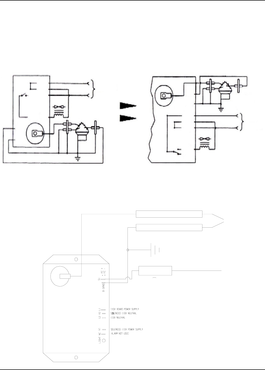
The B. GND terminal is used to ground the burner and to complete the flame current signal circuit. This terminal is
new for systems that used the older version of the Fenwal board. This terminal must be connected to the burner
(chassis) ground not only to ensure the best, long term, stable flame signal, but also to ground the burner for
proper sparking.
The use of a burner ground terminal eliminates the problem of loss of flame sense signal due to a missing or loose
neutral or ground (green) wire at the 120 VAC power source. The new board has been designed such that reversing
the polarity of the 120 VAC line does not cause a loss of flame signal. Thus providing a more reliable flame signal
along with a reduction of nuisance lockouts, due to its design and the use of the B. GND terminal.
New Fenwal Board Wiring
L2
V2
(B) V1
S1
E2
GAS
VALVE
H.V.
E1
120
VAC
BURNER
NEU.
HOT
L2 GAS
VALVE
120
VAC
NEU.
HOT
V2
L1
V1
NC
BURNER
H.V. S1
B. GND
IGNITOR
Part No. HF-4624
Flame Safety Board
BURNER
GROUND
(B. GND)
Old version with Remote Flame Sense. New version with Remote Sense using existing
spark and remote sense electrodes.
FLAME ROD
Note that terminal E2 on the old version has been replaced by terminal B.GND on the new board.
(A) L1
Wiring Reference
Portable Dryer Troubleshooting
40
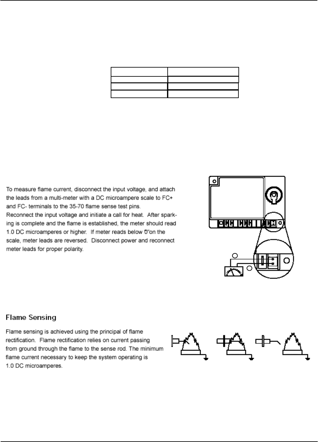
Fenwal Board Troubleshooting
On-Board Diagnostics
The LED will flash on for 0.2 seconds then off for 0.2 seconds to indicate an error condition.
The pause time between error codes will be 2.5 to 3.0 seconds. During power-up, the LED will light
for one second and then turn off to indicate normal operation.
LED Indication Fault Mode
Steady on Internal Control Failure
2 Flashes Flame Fault**
3 Flashes Ignition Lockout Fault
** May indicate either that a flame was detected during
pre- or post-purge, or that there is a flame sensing error.
Micro Amp Meter
Flame
Test
S1
FC+
FC-
+
-
Flame
Test
If a lockout occurs, the board will have to be reset
by shutting off the power to the board.
S1
Measure Flame Current
YES NO NO
BURNER BURNER BURNER
Wiring Reference
Portable Dryer Troubleshooting
41
Coil
V1
20 SEC SAFETY
12 VOLTS DC
120 VOLTS AC
WHT
WHT
FENWAL BOARD
WHT
WHT
OR
COMMON
COMMON
Neutral
COIL
Normal Closed
Normal Closed
WHT
OR
Coil
WHT
WHT
BLK
TER. 1-5 (12 VOLTS DC)
TER. 6-8 (110 VOLTS AC)
WHT
BRN
BLK
Neutral
BLK
BRN
120 VOLTS AC
20 SEC INPUT
OR OR
MAIN CONTROL BOX
ALL WIRES COME FROM
BRN
BURNER LIGHT
OR
OR
OR
BRN
OR
BLK
NEUTRAL
L1 V2 L2
S1
E2
TIME
DELAY
FLAME
SENSOR
IGNITOR
1
2
3
4
5
6
7
8
Flame Control Circuit
Wiring Reference
Portable Dryer Troubleshooting
42
IGNITOR SENSOR
FLAME
DELAY
TIME
E2 S1
L2
V2
L1V1
FENWAL PART# HF-4624
12 VOLTS DC
20 SEC SAFETY
VAPOR LIMIT
HOUSING LIMIT
VAPOR
HOUSING
LIQUID
LOW HIGH
110 VOLTS AC
NEUTRAL- - - - WHT
L1 BURNER
PUR
RED
YEL
ORG
WHITE
BLK
BLACK
BLK
BRN
BROWN
WHITE
BLACK
PURPLE
PURPLE YELLOW
YELLOW
ORG
ORG
ORG
ORG
ORG
YEL
RED
PUR
WHT
BURNER LIGHT - BRN
110 VOLTS AC
TER. 1-7 (12 VOLTS DC)
TER. 8-10 (110 VOLTS AC)
ORG
ORG
20 SEC INPUT
7
6
5
4
3
2
1
TO BURNER CIRCUIT
N/C
N/O
COM
* MERCOID TERMINALS
J4-20 FOR 1 FAN DRYERS
J4-18 FOR 2 FAN DRYERS
8
9
SWITCH CLOSES WHEN
PRESSURE IS SENSED
BROWN
MERCOID SAFETY PNK
BROWN
MERCOID SAFETY
RELAY
GREY
BLK
WHITE WHITE
BROWN
t
o
RB
BROWN
SOLENOIDS
HONEYWELL THERMOSTAT
PART# D03-0047
WHITE
BRN
MERCOID
PRESSURE SWITCH
MERCOID
SWITCH
WIRING
GREY BROWN
BLACK
BLK
PNK
E1
Fan Burner Circuit for Canadian Models Only
Wiring Reference
Portable Dryer Troubleshooting
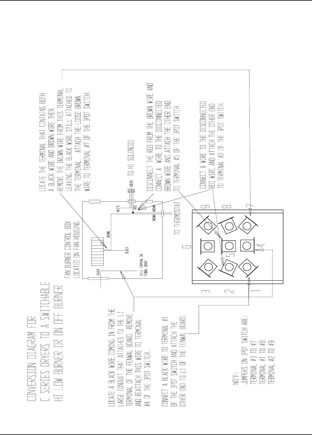
43
Conversion Diagram For C Series Dryers To A Switchable
Hi/Low Burner Or A On/Off Burner
Wiring Reference
Portable Dryer Troubleshooting
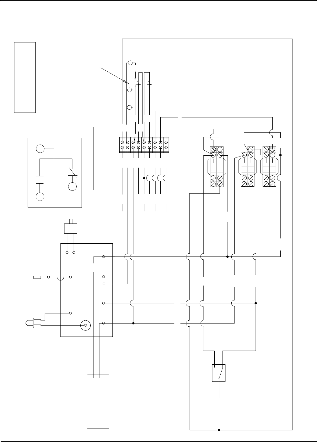
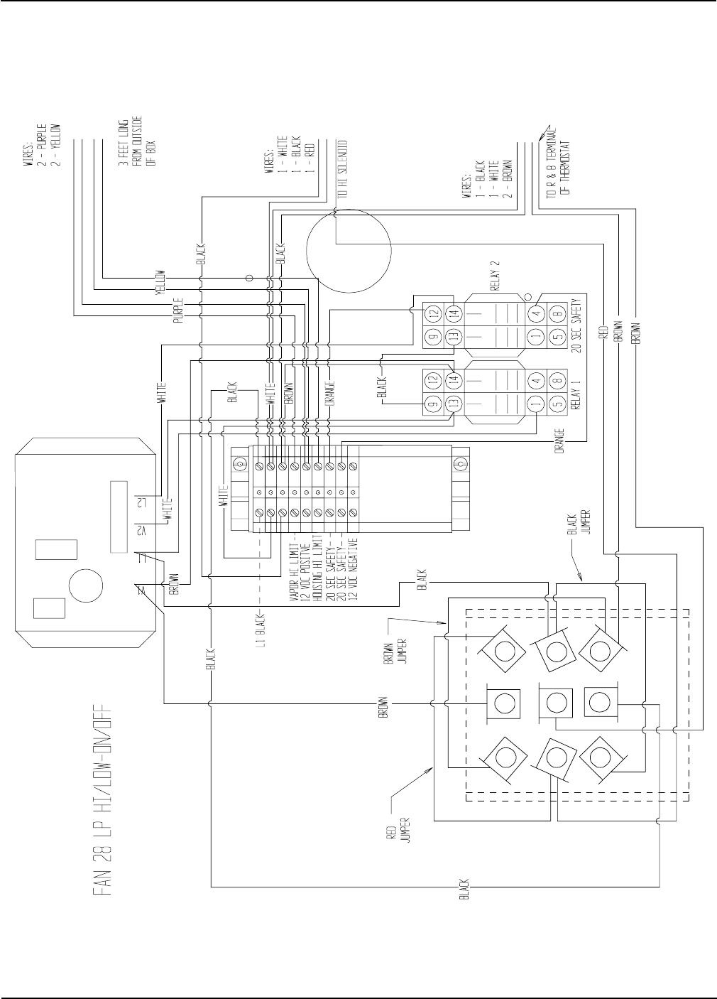
44
Fan 28 LP Hi/Low-On/Off
Wiring Reference
Portable Dryer Troubleshooting
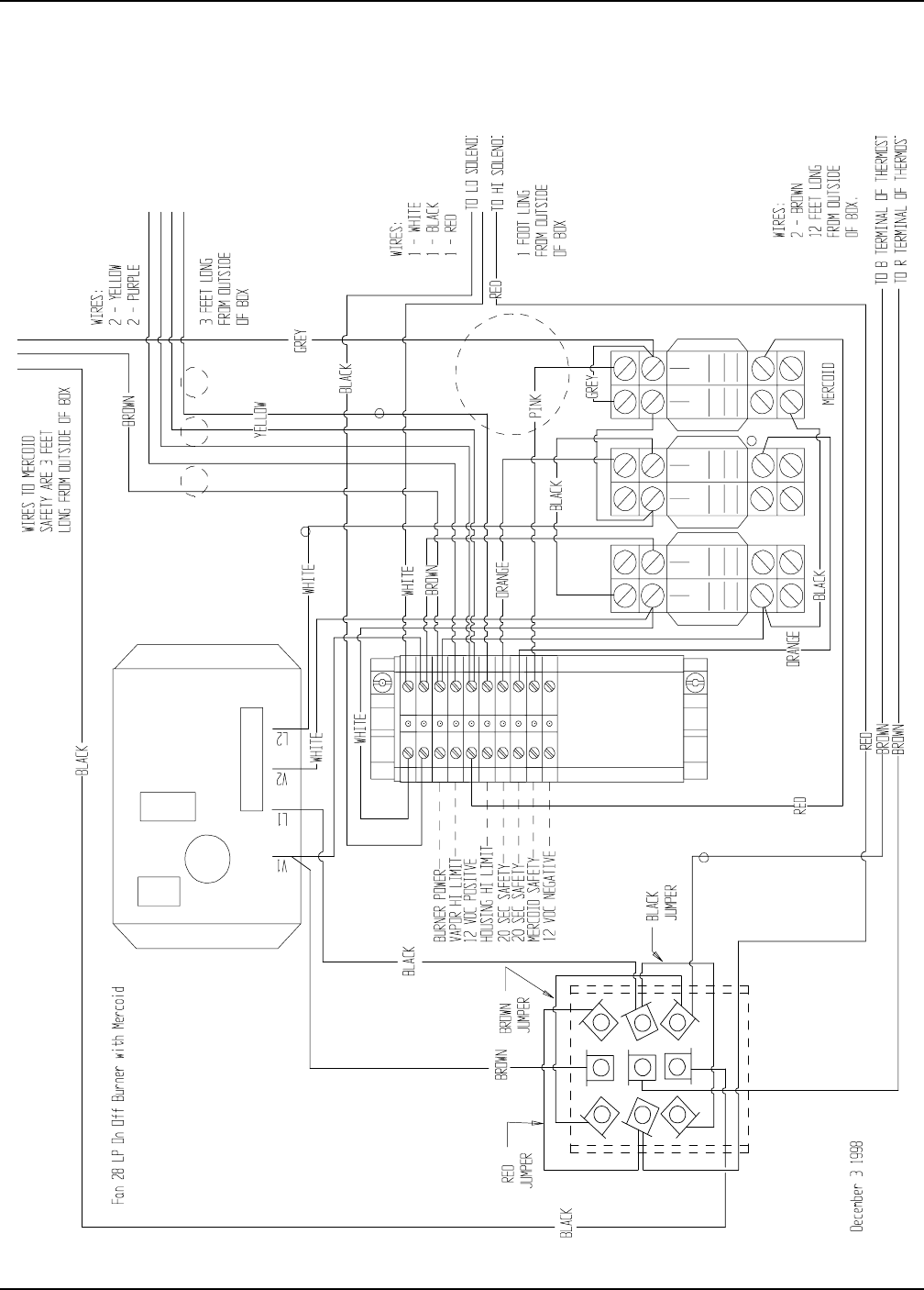
45
Fan 28 LP Hi/Low-On/Off Burner With Mercoid
Wiring Reference
Portable Dryer Troubleshooting
46
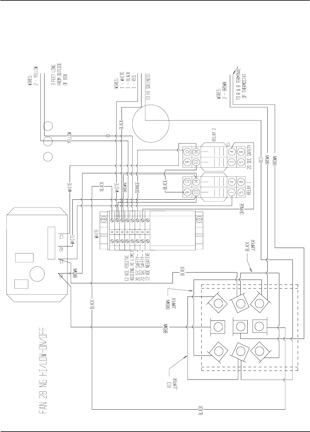
Fan 28 NG Hi/Low-On/Off
Wiring Reference
Portable Dryer Troubleshooting
47
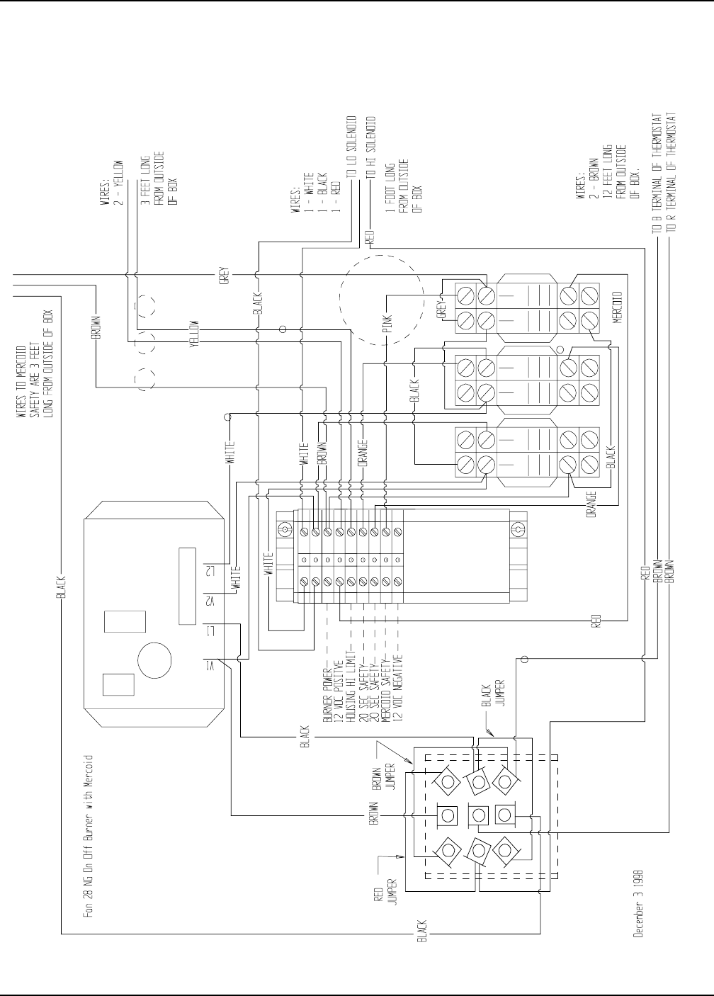
Fan 28 NG Hi/Low-On/Off Burner With Mercoid
Wiring Reference
Portable Dryer Troubleshooting
48
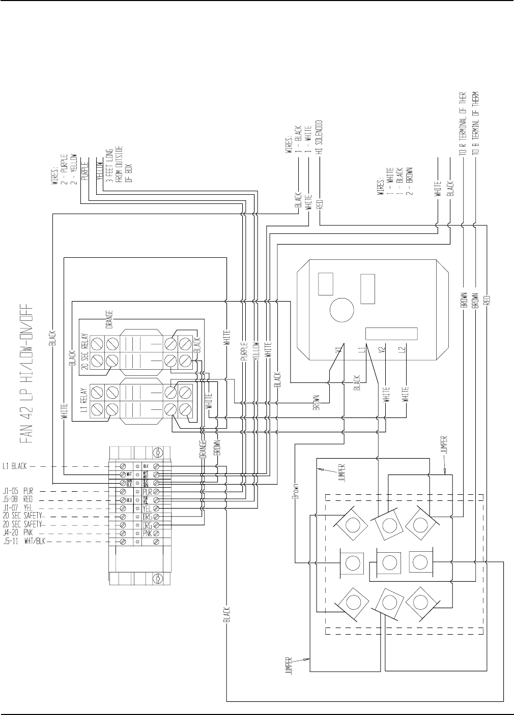
Fan 42 LP Hi/Low-On/Off
Wiring Reference
Portable Dryer Troubleshooting
49
Fan 42 LP Hi/Low-On/Off Burner With Mercoid
Wiring Reference
Portable Dryer Troubleshooting
50
Fan 42 NG Hi/Low-On/Off
Wiring Reference
Portable Dryer Troubleshooting
51
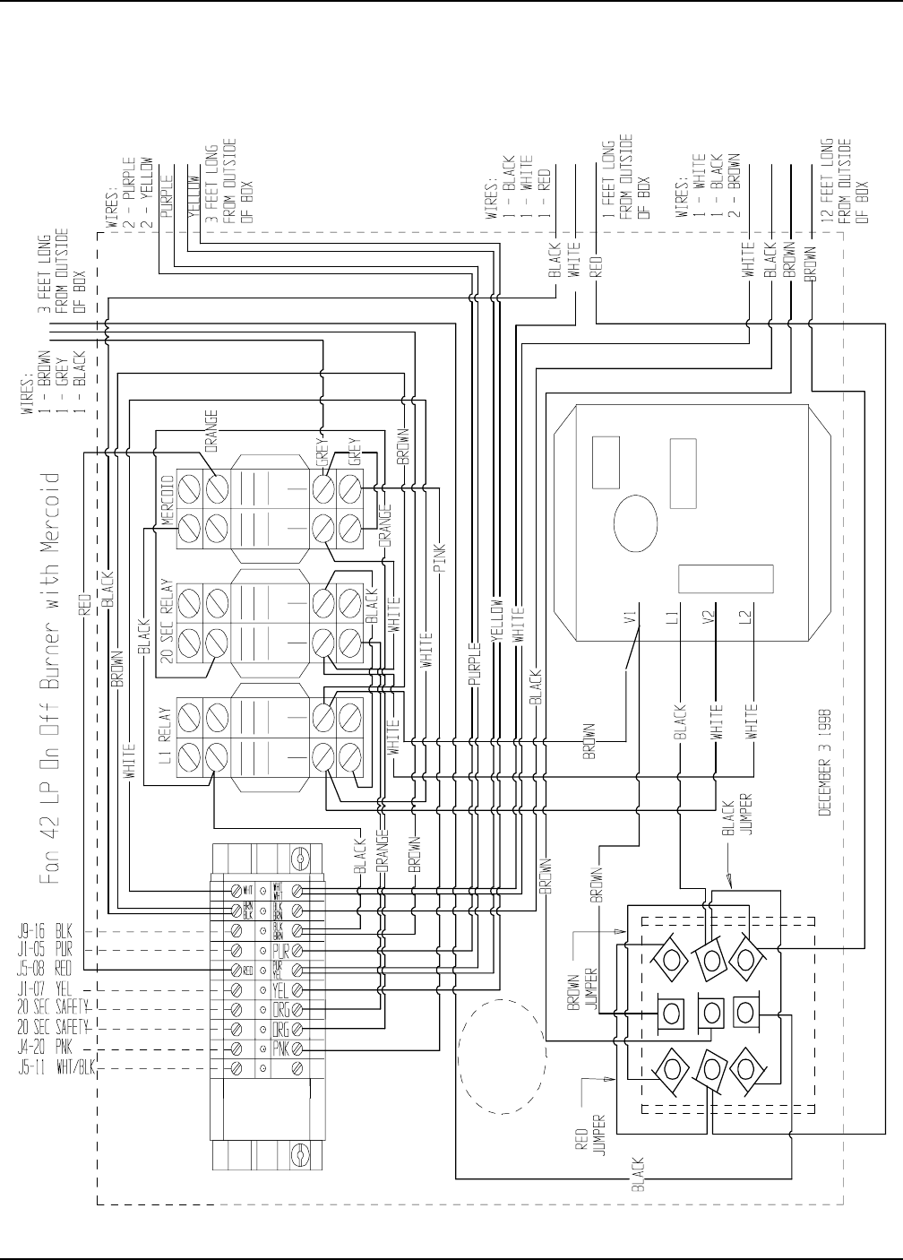
Fan 42 NG Hi/Low-On/Off Burner With Mercoid
Wiring Reference
Portable Dryer Troubleshooting
52
SCR Drive Circuit
To Coil
WITH POWER WIRES
UPPER POWER STRIP
TO TERMINAL ON CONTACTOR
SCR
S C R Board
To SCR Drive Motor
F +
F -
L 1
L 2
A -
A +
A -
A +
L 1
L 2
Fuse
220 Volt
COIL
L1T1
T2 L2
A2 A1
PUR
SCR 2
J6-4
J6-1
J8-20
SCR P3
SCR P2
SCR P1
SCR POWER
SCR NEUTRAL
J8-10
BLK
BLK
OR
OR
OR
3
2
1
7
5
8
6
P
P
P
W
Wiring Reference
Portable Dryer Troubleshooting
53
RTD Temperature Sensor
BLACK 20 GA.
WHITE 20 GA.
REAR FRONT
INSIDE GRAIN COLUMN CONDUIT
TO UPPER CONTROL BOX
WHITE S1
BLACK S2
PLENUM
SCR
UNLOAD
MOTOR
11XX
RIGHT FIXED
GRAIN HIGH
LIMIT
OUTSIDE LIGHT
TEMP. SENSORS
LOAD
MOTOR
LOAD MERCURY SWITCH
UPPER
BOX
JUNCTION
FAN
SOLENOID
BURNER
HI-LOW
THERMO
AIR SWITCH
LEFT FIXED
GRAIN HIGH
LIMIT
TEMP. SENSORS
GAS PIPE TRAIN
LOWER
BOX
JUNCTION
SOLDERED AND INSULATED INSIDE CONDUIT
BLACK 20 GA.
WHITE 20 GA.
REAR FRONT
INSIDE GRAIN COLUMN CONDUIT
TO LOWER JUNCTIONL BOX
WHITE S1
BLACK S2
SOLDERED AND INSULATED INSIDE CONDUIT
Wiring Reference
Portable Dryer Troubleshooting
54
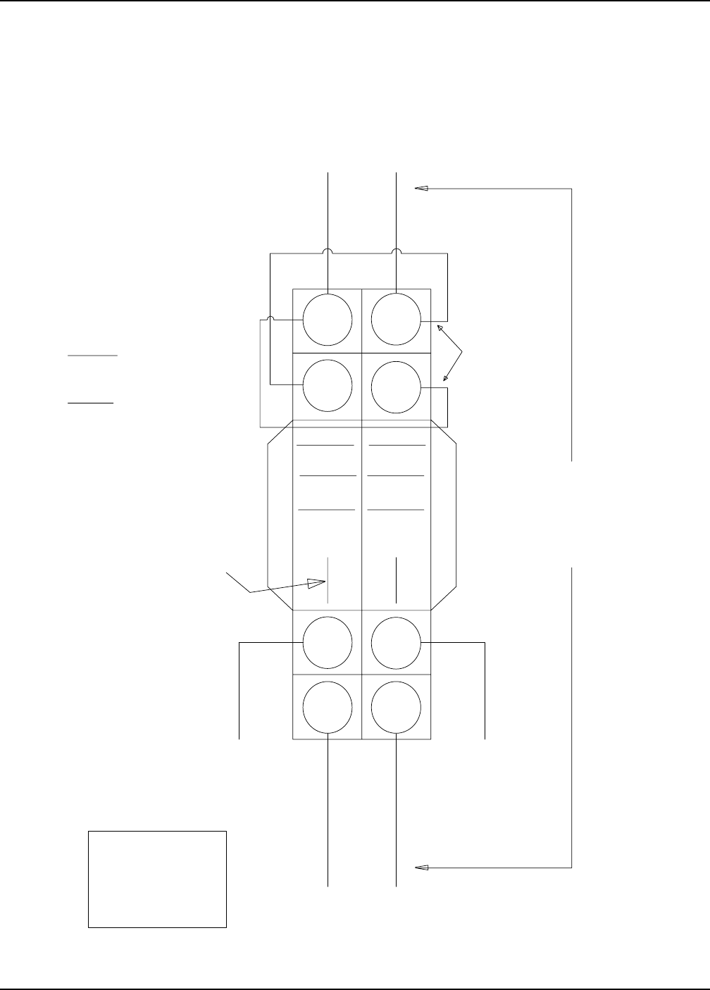
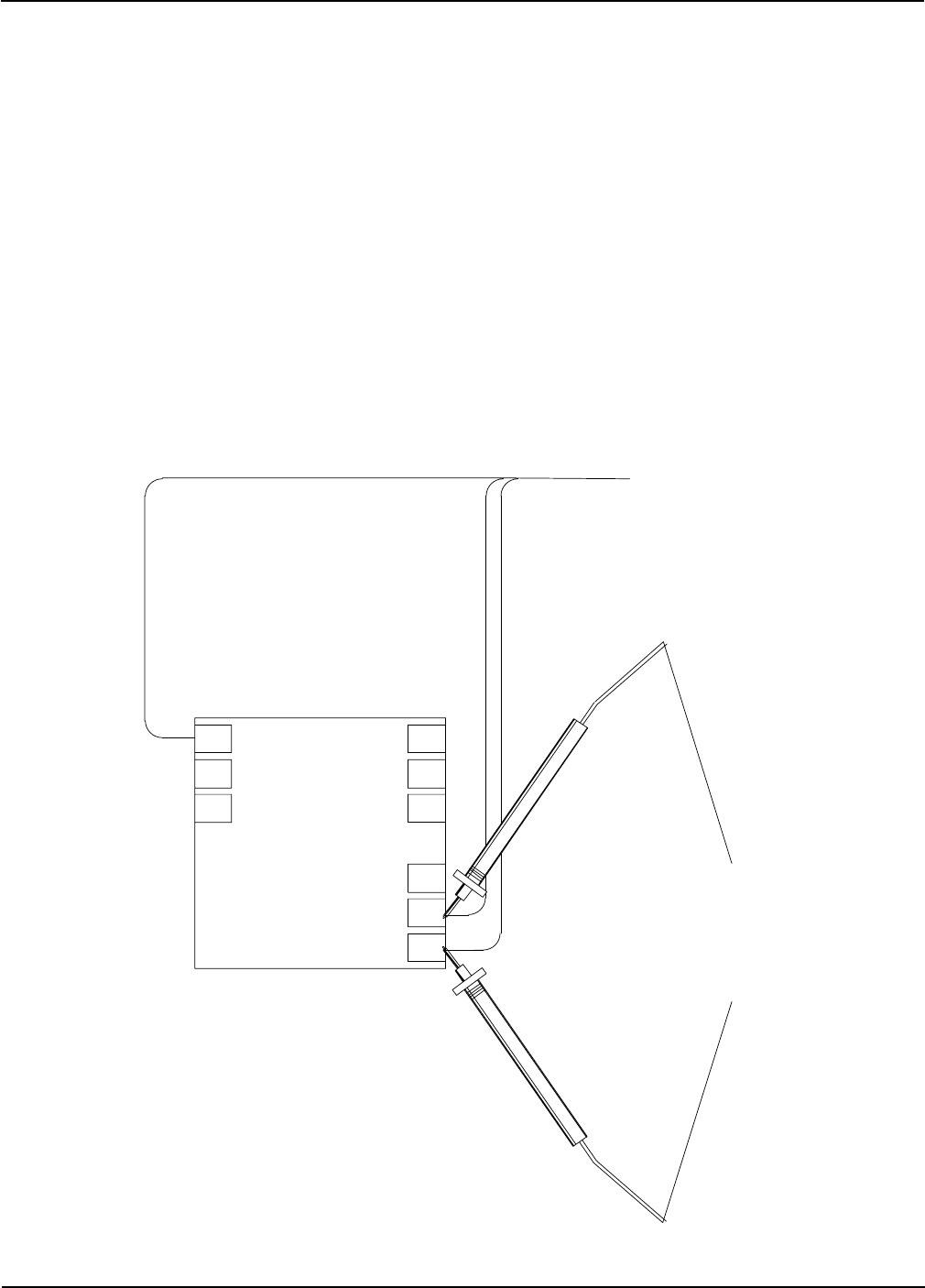
Test Procedure for E.M.C.S. Dryers
IF NONE OF THE MEASUREMENTS = 3.4 K,
THEN CHECK EACH INDIVIDUAL SENSOR.
IF MEASUREMENTS DO NOT = 3.4 K
CHECK CONNECTIONS IN WHITE
JUNCTION BOX ON FAR LEFT AND
RIGHT SIDES FACING THE FAN END.
IF OHMS DOES NOT = 3.4 K
CHECK LOWER AND UPPER TERMINAL
STRIP (ON SINGLE MODULES CHECK S1 & S2
)
(ON DOUBLE OR TRIPLE MODULES
CHECK J6-9 TO J6-6 = 3.4 AND
CHECK J6-11 TO J6-8 = 3.4)
MOISTURE
CONTROL
THERMOSTAT
65
4
123
7
89
J5-3
S1 S2
3.4 ON 20K
SCALE AT
70 DEGREES
USING OHM METER BEGIN CHECKING
THE SENSORS FOLLOWING FIG. 1
FIG.1
E.M.C.S. PORTABLE DRYERS
Wiring Reference
Portable Dryer Troubleshooting
55
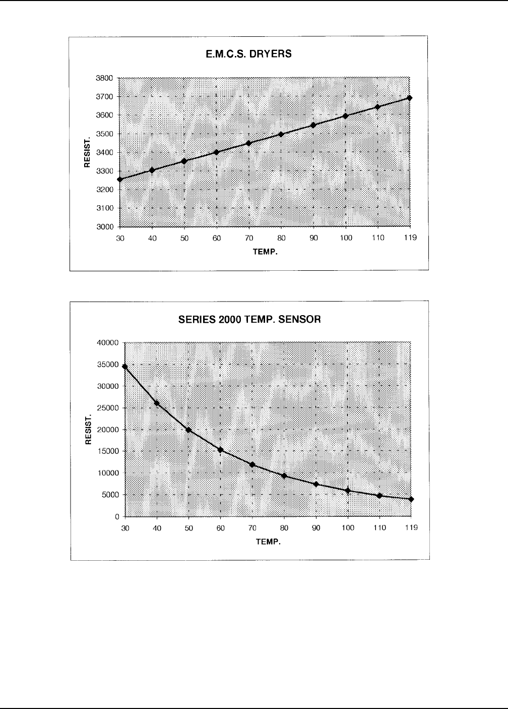
Temperature Charts
We use two (2) different types of sensors (NTC thermistor on the Competitor Series 2000, and an
encapsulated sensor on the E.M.C.S dryer) in our dryers. The resistance of the sensors varies according to the
outside temperature. For example, on the E.M.C.S. dryers, for every one (1) degree rise in temperature the
resistance increases 4.8 ohms. However, on the Competitor Series 2000 dryer, the sensor reacts just the opposite,
the resistance rises with colder temperatures. The charts displayed above will help when troubleshooting any
sensor problems.

Portable Dryer Troubleshooting
56
• If 220 volts AC is present across input of
the SCR drive board (L1 and L2) then
check for voltage across the output of the
board. Change your voltmeter to check for
DC voltage at a range above the 200 volt
scale. Put the leads across A+ and A-. The
voltage across these two points will vary
depending on where the speed control poten-
tiometer is turned. Also try turning the poten-
tiometer up and down. The voltage should go
from zero to approximately 180 Volts DC. If
zero voltage is present across the A+ and A-
terminal, first try to disconnect the wires from
these two points and then check for DC volts
again. If the voltage returns, suspect a bad
motor or a problem in the wiring to the motor.
If the voltage does not return, suspect a bad
DC drive board.
• The DC drive system on the portable
dryer is used to control the output of grain
from the dryer. It is adjusted from the
front of the control box using the high and
low metering roll potentiometers. Compo-
nents used in this circuit are the SCR
contactor, SCR drive board, DC motor/
gear box, and the input/output board from
the Electronic Monitoring Control System.
• All voltage for the drive system comes
from terminals 1-(L1) and 3-(L2) of the
SCR contactor. There should be 220 volts
AC across these two points even if the
unload system is turned off. If this voltage
is zero, check your incoming main power.
• When the unload system is turned on you
should be able to observe the SCR
contactor energizing. The power to the
contactor should turn on and off with the
unload switch. You can check for power by
putting an AC voltmeter across terminals
A1 and A2. Across these points you
should read 120 Volts AC. Also on the top
of the contactor you can see a plunger pulling
in whenever the contactor coil gets power. When
the contactor is energized, power is transferred
from terminals L1 and L2 to terminals T1 and
T2. Understand that L1 and L2 are the Input
of the SCR contactor and T1 and T2 are the
Output of the contactor.
• The wires attached to A+ and A- go directly to
the DC drive motor on the dryer. You may
remove the top cover of the motor and check
for the same DC voltages mentioned above at
the motor. If the voltage is not present try to
disconnect the wires, then check for DC volts
again. If you do not get any voltage then look
for a broken or loose wire between the motor
and the drive board terminals.
• If the voltage is present suspect the motor
or the gear box. Removing the motor from
the gear box and trying to run the motor only
is one way of narrowing down the problem, or
you may want to remove the chain and see if
the metering rolls are froze up. Using a pipe
wrench is an easy way to try and rotate the
metering rolls.
Symptoms: Metering Roll will not turn,
dryer shutdown-"Metering Roll Drive Failure"
DC Drive Metering Roll System
• Next if all the above checks out okay, put
your voltmeter across terminal L1and L2 of the
SCR drive board. You should get 220 Volts AC
across these points when the Unload Switch Is
Troubleshooting Tips
in the 2 Speed position. If this is present
then the SCR contactor and input/output board
are okay.
Metering Roll Operation
Check the SCR Drive Board
Check the Motor

Portable Dryer Troubleshooting
57
Fenwal Ignition System
Symptoms: Burner will not light, dryer
shutdown for "Loss of Flame"
Fenwal Ignition Operation
has to ignite and sense flame or it concludes
no flame is detected and begins a "Loss of
Flame" shutdown. If you have power on the in
put terminals and no voltage on the output ter-
minals, unload the secondary (take the wires off
of V1 and V2) and recheck for voltage. If no
voltage is present then suspect a bad Fenwal
board. If power returns, look for a bad so-
lenoid valve or a problem in the wiring.
Note: All of the above voltage checks can be
bypassed if you can hear one or more of the
solenoids on the gas train snap on after the 10
second purge delay. This is true because the so-
lenoids are connected across V1 and V2, and
for the solenoids to come on, power must be
going through the Fenwal board. Also during
the four(4) second ignition period the trans-
former is energized and you should be able to
observe sparking across the ignitor. If the sole-
noids snap, but no ignition takes place, check
for loose ignitor wires or check the ignitor con-
dition/ignition gap (1/8 " to 3/16"). Remember
even if flame is sensed the sparking will discon-
tinue after the ignition period (4 seconds).
Continued on page 55.
• The Fenwal Ignition System ignites the
burner and monitors the flame. Once 120
VAC is applied to the Fenwal, the solenoids
are powered up and the transformer begins
ignition through the ignitor. If flame is
sensed during the ignition period (about
4 seconds), the transformer is turned off,
but the solenoids stay on. If no flame is det-
ected after the ignition period, both the solenoids
and transformer lose power and the dryer
begins a shutdown sequence.
• All voltage for the Fenwal Ignition
System is derived from the input/output
board of the Electronic Monitoring
Control System. For ignition to occur:
1. The fan must be turned on.
2. The pressure switch in the plenum
must indicate the fan is operating.
3. The burner switch must be in the
auto or manual position.
4. The dryer must go through a 10
second purge delay, which is indicated
on the LCD screen.
These steps must take place before troubleshooting
of the Fenwal System can occur. The following
assumes the above steps have been taken.
• The Fenwal Board located in the fan can
control box on the dryer has seven(7)
terminals. They are L1, L2, V1, V2, S1, S2
and E2. L1 and L2 are considered the input
to the board. After the 10 second purge delay,
an AC voltmeter connected Across L1 and
L2 should read 120 Volts AC. If this is true,
you can assume the input/output board is
operating properly and the problem is in the
ing
Fenwal Ignition System. If no voltage is
present after the 10 second purge delay,
check for voltage going through the auxil-
iary switch mounted on the side of the fan
contactor for that burner. This switch has
to close before the Fenwal gets power. If
this is OK, check the appropriate output
on the input/output board for that burner.
• If voltage is present across L1 and L2,
check for voltage across the Output of
the Fenwal board. The output terminals
are V1 and V2, and they will also have
120 VAC across them for approxi-
mately four(4) seconds. The four(4)
seconds is the amount of time the Fenwal
Troubleshooting Tips
Fenwal Ignition Operation
Fenwal Troubleshooting

Portable Dryer Troubleshooting
58
• Hearing the solenoids snap on after the
10 second purge delay means that power
is coming to and through the Fenwal
board. The Fenwal board is probably okay.
• If flame is sensed, the power to the sole-
noids stays on but the power to the ignitor
always goes off after about four(4) seconds.
• Power to the low pressure solenoid is al-
ways on anytime flame is sensed. This is
because the power to the low solenoid is
hooked directly across terminals V1 and
V2 of the Fenwal board.
• Power to the high pressure solenoids is
controlled by the Plenum thermostat. One
side of the solenoid is hooked to V2(neutral)
and the other side is run through the nor-
mally closed switch of the thermostat and
then back to V1. This is how the burner is
made to cycle. When the plenum is below
temperature, power is run through the ther
mostat to the high pressure solenoid. When
temperature is reached, the thermostat opens
and the high solenoid loses power.
• L2 and V2 are connected internally in the
Fenwal, and they must be nuetral.
Hints • Make sure that the ignitors are mounted
correctly through an opening in the burner
skirting. Also, make sure that they are not close
enough to the edges of the opening to cause a
spark to jump the skirting, instead of between
the ignitors.
• Be sure that the ignitor tips are no more than
1/8" apart from each other.
• Make sure that the wire connections on the
ignitors are good and tight.
• On stubborn lighting burners reverse the
direction the ignitor tips are facing. Instead of
having the tips pointing toward the fan or burner,
change the direction so the tips are facing the ex-
haust end of the dryer. (This is especially true on
burners with no burner cone installed (i.e. Nat-
ural Gas).
Ignitor Tips
Fenwal Ignition System continued...
Troubleshooting Tips

Portable Dryer Troubleshooting
59
Hints
Metering Roll Sensors
Metering Roll Sensor Operation
• The T3 (out) terminal is what delivers
the metering roll information back to
the input/output board in the main con-
trol box. The information for the meter-
ing roll on the left side of the dryer is
sent on a yellow wire and goes to termi-
nal J5-16. The information for the me-
tering roll on the right side is sent on a
blue wire and goes to terminal J5-19.
• You can use a DC voltmeter to observe
this pulsing voltage. The best place to
check for this voltage is directly on the
input/output board located in the very
back of the lower control box on the
dryer. Check for a pulsing voltage from
J5-16 to J5-12 (negative) and J5-19 to
J5-12 (negative). Across each of these
test points you should be able to ob-
serve a pulsing DC voltage when the
metering rolls are turning. You should
be able to speed up or slow down the
pulses by turning the speed of the me-
tering rolls up or down.
Note: Because a digital voltmeter cannot
react fast enough you may not see a full
12 volts DC, instead you may see a pulsing
from zero to about eight(8) volts.
• All voltage for the metering roll sensors
is derived from the input/output board
of the Electronic Monitoring Control
System. The sensors are operated with
12 Volts DC from terminals J5-9 and J5-
12 on the board. When checking for volt-
age the negative or black probe (-)of a
voltmeter should always go to terminal
J5-12.
Always use j5-12 for the negaitve anytime you
check for any DC voltage on the dryer.
Then put the red probe (+) of the volt-
meter on terminal J5-9. Across these
two points there should be 12 volts DC.
This voltage needs to be checked, but
you can be reasonably assured the 12
volts DC is present if the rest of the dryer
is operating. Check for this voltage on
the terminal strip in the upper control
box.
• 12 volts DC is transmitted from J5-8
and J5-12 directly to the metering
roll sensors located on the back of the
dryer. Each of the metering rolls is en-
closed in a white plastic box mounted to the
back of the metering rolls. Inside each box
is the metering roll sensor and the metering
roll wheel.
• Each sensor has three(3) wires con-
nected to it. Two(2) of these wires are
• When checking for a pulsing voltage on
J5-16 or J5-19 you should always leave
the voltmeter across the terminals for
about 30 seconds. Watch the meter
closely. Each pulse should be about the
same length and about the same time
apart. If this is not true, suspect a prob-
lem with the sensor on the back of the dryer.
• Each metering roll on the portable dryer
has a sensor mounted to read pulses as
the metering roll is turning. These
pulses are transmitted to the input/out-
put board of the Electronic Monitoring
Control System. The computer inter-
prets this information and then displays
the data on the LCD screen.
Symptoms: No BPH, Total Bushels, RPM dis-
played on LCD or dryer shutdown with metering
roll problems
the incoming 12 volts DC (the T1-+12V and
T2-GND terminals), and one is a pulsing
12 volts DC back to the input/output board
(the T3 out terminal). Checking across T1
and T2 will verify that 12 volts DC is getting
to the sensor.
Troubleshooting Tips

Portable Dryer Troubleshooting
60
Air Pressure System
Symptoms: Dryer will indicate a "Loss of Airflow"
negatives for the black probe(-) of your
voltmeter. Some of the terminals that
may be used for the negative(-) are J5-11,
J5-12 or J5-13.
• To check fan #1 for air pressure with a
voltmeter:
1. Turn on the dryer.
2. Place the black probe(negative) of
your voltmeter on J5-11 or J5-12.
3. Place the red probe(positive) of your
voltmeter on J1-13. At this point
there should be zero volts here be-
cause the fan is not running.
4. Turn on the fan and watch your volt-
meter.
• If the air switch is adjusted properly you
should have zero volts across these test
points when you first turn on the fan. Af-
ter the fan has run up to about one half of
its normal operating speed you should see
the voltmeter change from zero volts to 12
volts DC. This also works in reverse when
turning off the fan. After the fan is first
turned off, the voltmeter should still show
12 volts DC until the fan has slowed down
to about one half of its operating speed.
This is because even though the fan is
turned off it is still turning and developing some
pressure in the plenum.
• After turning on a fan the computer must
get a signal from the air pressure switch
telling it that the fan is actually running
and the plenum has been pressurized. If
the switch does not show the air pressure
within 20 seconds a "Loss of Airflow"
shutdown occurs.
Airflow Operation
• This error message indicates that the fan
is running and the air pressure in the ple-
num did not pressurize. First, verify that
the fan is running, and the dryer is full of
grain. There must be grain in the dryer or
no pressure will develop. If the fan does
come on and the dryer is full of grain, but
a "Loss of Airflow" shutdown still occurs,
check the air pressure switch circuit.
• Watching the blue light in the fan switch
is the easiest way to tell if the air pres-
sure switch is sensing air pressure. Each
air pressure switch has a light in the fan
switch that will only come on if air pres-
sure has developed. Turn on the fan and
after it has run up to about one half of its
operating speed the light should go on. If
the fan light is not coming on then the air
pressure circuit is not sensing pressure.
• Try adjusting the air switch on the front
of the plenum to see if it is just out of ad-
justment. Use a straight blade screw-
Troubleshooting: "Loss of Airflow"
• When inspecting the sensor make sure
that the wheel going through the sensor is
positioned in the center and is not touch-
ing either side. If the sensor is scratched
it is either bad or will probably go bad.
driver and turn the adjusting screw coun-
terclockwise. Turning it this way makes
the switch more sensitive to pressure and
will turn on the light easier.
• If adjusting the screw does not solve your
problem consult the layout diagram of the
input/output board. Look for the input for
the problem switch. Example: Fan #1
switch's input is J1-13. This is a 12 volt
DC input and it can be checked with a DC
voltmeter. One of the following conditions
will exist when checking this input.
NO AIR PRESSURE---ZERO VOLTS
HAS AIR PRESSURE---12 VOLTS DC
Remember when checking for 12 volts DC
you should always use one of the DC
Troubleshooting Tips

Portable Dryer Troubleshooting
61
Symptoms: Dryer runs for only a short period of
time, then a shutdown occurs.erature Operation
•This message indicates that the vaporizer on
an LP Dryer is not properly adjusted. LP
(liquified petroleum) must be vaporized
before the burner can operate properly. If
LP is being fed to the dryer it must run
through a vaporizer before it can be burned.
If the vaporizer is getting the fuel too hot it
will cause a Vapor High Limit shutdown.
•The vaporizer is located in the fan/heater
unit. It is wrap of pipe mounted inside the
fan can directly in front of the burner. It
can be seen by looking through the inspec-
tion door on the side of the burner.
•To properly adjust the vaporizer a 1/2"
wrench is needed. Knowing that the gas
can get too hot, you must feel the pipe train
before the regulator to check this tempera-
ture. This point may be very hot so be
careful while checking the temperature.
The temperature before the regulator must
be warm to the touch. This point cannot be
hot, nor can it be cold...only warm. Use the
1/2" wrench to loosen the hold down
bracket on the vaporizer. Move the vapor
izer away from the flame to cool down the
pipe train or move it closer to the flame to
make the pipe train warmer.
•The dryer will shutdown but will probably
restart as soon as the computer is reset.
This is because the high limit is an auto-
matic reset and after the dryer shuts down it
allows the pipe train to cool down.
•After the dryer is reset, it will run from a
few seconds to a few minutes and then
shutdown again. This is because the
Vapor High Limit is heating up again as
1. Dryer must be full of grain.
2. Light in the fan switch can be used exactly
like a voltmeter to test.
3. Make adjustments of the pressure in one
quarter turns.
4. Make sure the air tube in the plenum is
not plugged after sitting over the summer.
5. Check the bulb in the fan light. It is a 12
volt bulb.
Hints
• If all the above fails to work then remove
the two wires while blowing into the air
tube. Blowing into the switch is the same as
having air pressure in the plenum. You
should have an open circuit until you blow
into the switch, then it should close. If the
switch does not close try adjusting it, or
replace it with a known good one.
Troubleshooting Tips
Vapor High Temperature
Troubleshooting: Vapor High
Temperature

Portable Dryer Troubleshooting
62
soon as the burner is turned on. The
vaporizer must be adjusted to solve this
problem.
Using J5-11 as the negative test point for all voltage
tests, check for 12 volts DC using the following termi-
nals to help diagnose the problem:
Fan #1-J1-5 Fan #2-J1-6
Fan #3-J2-5 Fan #4-J2-6
Fan #5-J3-5 Fan #6-J3-6
Remember that each of these input terminals is part of
the main safety circuit of the dryer, and each must
have 12 volts DC on it before the dryer will operate.
Vapor High Limit Hints
1. Anytime you adjust the Vapor High you
should wait and be sure that the pipe train
temperature stays constant. It may slowly
allow the pipe train to get hotter or colder
the longer the dryer runs.
2. If a dryer is shutting down constantly from
a Vapor High Limit, it may also be caused
from a gas line that is exposed to direct
sunlight. If the fuel line to the dryer is
exposed to direct sunlight, the liquid in
the line will start to vaporize before it
even gets to the dryer. Then, when it runs
through the vaporizer it gets too hot and
causes a shutdown (no matter where you
try and adjust the vaporizer). This prob-
lem can be helped by insulating the gas
line from outside heat.
3. In extreme cases the vaporizer may have
to be changed before it will run the proper
temperature. Example: If a dryer has a
burner with a three wrap vaporizer and the
dryer is located in the southern United
States, you may have problems adjusting
thevaporizer far enough from the flame.
In this case, you may have to install a two
wrap vaporizer.
Troubleshooting Tips
The two wrap has less surface area and it
will not heat the LP quite as much. This
may also be true in colder climates where a
two wrap will not heat up enough. In this
case, the pipe train may develop frost or
even freeze the solenoids open.
4. The Vapor High Limit is an automatic reset
safety device. It will reset itself as soon as
its temperature drops below 190° F. Be-
cause the pipe train of the burner cools
down rapidly when there is a dryer shut
down, the Vapor High Limit will generally
be cool before the operator gets back to the
dryer. As soon as he hits the stop button to
reset the computer, it comes back up to
normal operation. It appears that the dryer
is shutting down for no apparent reason.
Usually if this happens the dryer will shut
down again a short while after restarting the
dryer.
5. If the LP tank feeding the dryer is getting
very low on fuel, it can also cause the
dryer to shutdown on a Vapor High Limit.
Before adjusting the vaporizer always
check the fuel level in the customers tank.
If the fuel pressure is very low, try suggest
ing that the tank be refilled. Usually this
will solve the problem.

Portable Dryer Troubleshooting
63
Out Of Grain Warning
•This message indicated that the dryer has
run low on grain. The shutdown occurs
when the loading equipment has run
longer than the time the operator has set on
the Out of Grain timer. The mercury
switch located on top of the dryer tells the
computer when the dryer is full or calling
for grain. The shutdown usually occurs
when the loading equipment is having
trouble keeping up with the output of the
dryer.
Possible Solution
•Look at the loading equipment to see if this
is the problem. Remember, the top hopper
of the dryer should always have grain in it.
If any of the side screens are opening up at
anytime, then you are losing heat along
with efficiency. This indicates that you are
not filling fast enough. Speed up the
loading equipment to the dryer.
•Using J5-11 for the test point ground, test
for 12 volts on J5-4 to test the load mercury
switch. This switch should have 12 volts DC
on it when the dryer is calling for grain and has
zero volts on it when thedryer is full.
Out of Grain Hints
1. The out of grain timer is only in use when
the fill switch is in the auto position. In
the manual position the top mercury
switch will still shut off the fill auger, but
the dryer will not shutdown if the source
of grain to the fill auger is depleted.
Troubleshooting Tips
Out Of Grain Warning Shutdown 2. Before setting the Out of Grain timer,
monitor how long it takes the dryer to
refill for shrink. Then, set the Out of
Grain timer accordingly. Example: If a
dryer takes six minutes to refill for
shrink, add an additional five minutes to
this, and use this as the amount of time to
program into the Out of Grain timer. The
additional five minutes is to avoid any
nuisance shutdowns. A lot of customers
don't want their fill augers to run empty if
the source of grain runs out. They may
want to set the Out of Grain timer closer
than the additional five minutes. (this is
fine, but caution the customer that it may
cause some nuisance shutdowns.)
3. For the Out of Grain warning to work
properly, the fill equipment must be large
enough to handle the capacity of the
dryer. You do not want the side columns
to get low on grain. This will allow the
airflow to escape from the dryer through
the side screens. If this happens you lose
efficiency and may start having a loss of
airflow shutdown.

Portable Dryer Troubleshooting
64
Troubleshooting Tips
This indicates that one of the Motor Overloads
has tripped, shutting down the dryer. Each of the Motor
Overloads is located in the upper main power control
box. They are all wired into a single series circuit that
goes to the input/output board on terminal J4-12. Be-
fore the dryer will start terminal J4-12 must have 12
volts DC present, or the Motor Overload shutdown will
occur.
Visually inspect each of the overloads. You can
tell by looking at them if a trip has occurred. Simply
press the reset handle on the overload to reset it. After
resetting the overloads press the stop button to clear the
error.
If no overloads are tripped try the following volt-
age tests: Using terminal J5-11 as the negative terminal
for all DC voltage checks. Look for 12 volts DC on
terminal J-419. This is the terminal that feeds power to
the Motor Overloads. If the 12 volts DC is present then
check for voltage on J4-12. During a Motor Overload
shutdown J4-12 should have zero volts. If you have
power going to and not returning to J4-12 inspect the
siring from J4-19 to the overloads and then back to J4-
12. If the wiring is okay, turn off all power to the dryer
and do a continuity check from J4-19 to J4-12. This
must be closed circuit to operate properly.
1. Each of the Motor Overload is run in a
series circuit. This means, if any of the
Motor Overloads trip, a shutdown will
occur. Visually inspect the overload to tell
which has caused the shutdown.
2. Even though GSI uses ambient compen-
sated overloads, hot weather or positioning
the dryer control box in the sunlight may
cause a Motor Overload shutdown to
occur. This can usually be tested by trying
to run the dryer with the control box door
open a little bit.
3. Each of the overloads has an adjustable
trip setting that can set up to 115 %. At
115% the overload will hold in longer
before it trips.
4. Always check amperages on the motors to
be sure that the problem is not in the
motor itself.
5. Remember that each motor has a built-in
service factor. This allow the motor to
actually run over the rated full load amps.
The motor manufacturers have allowed
GSI, on a number of applications, to run
motors over the full load amp rating. this
is possible because they are being used in
an air over application.
Motor Overload Helpful Hints
Motor Overload Shutdown
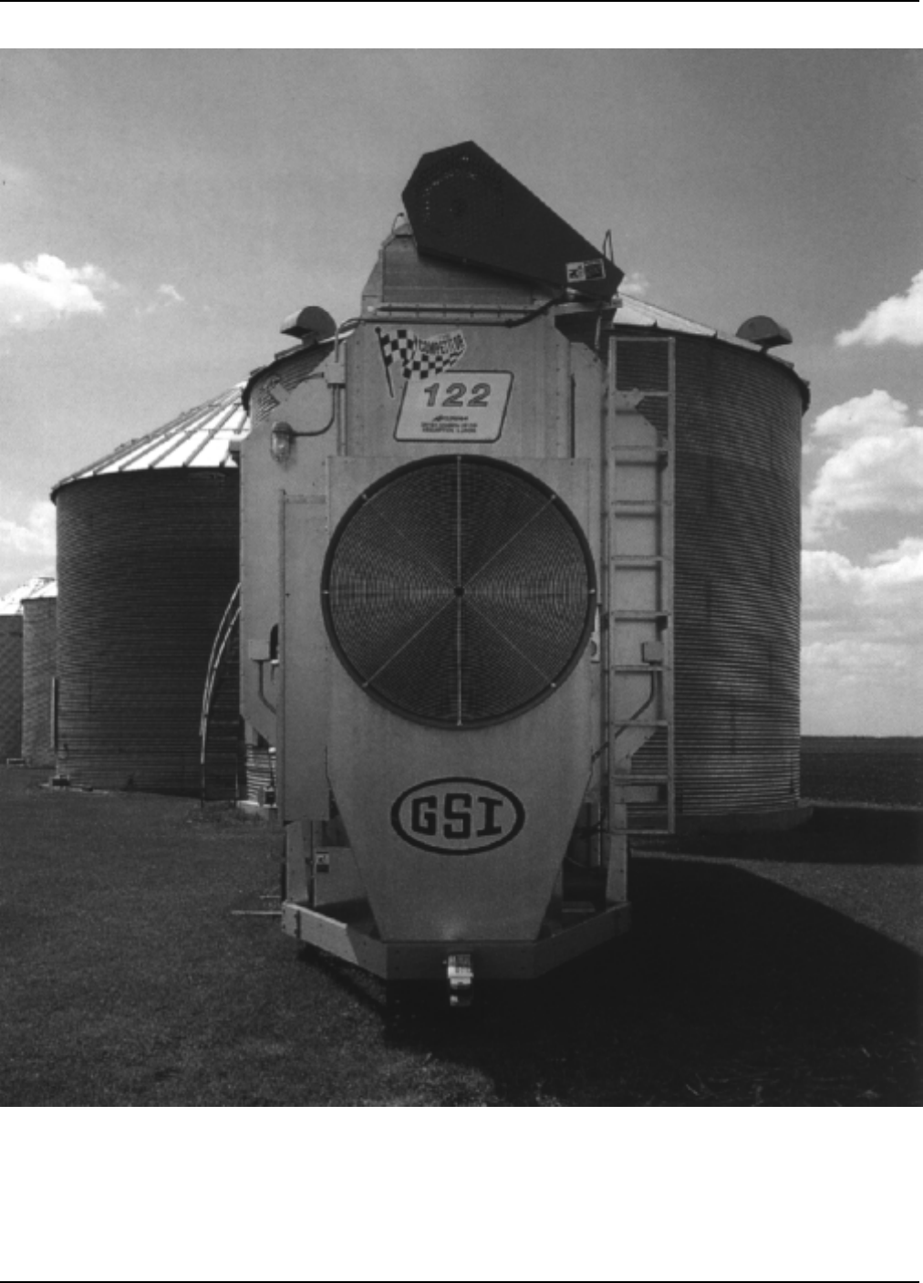
Portable Dryer Troubleshooting
65
Competitor Series 2000 Portable
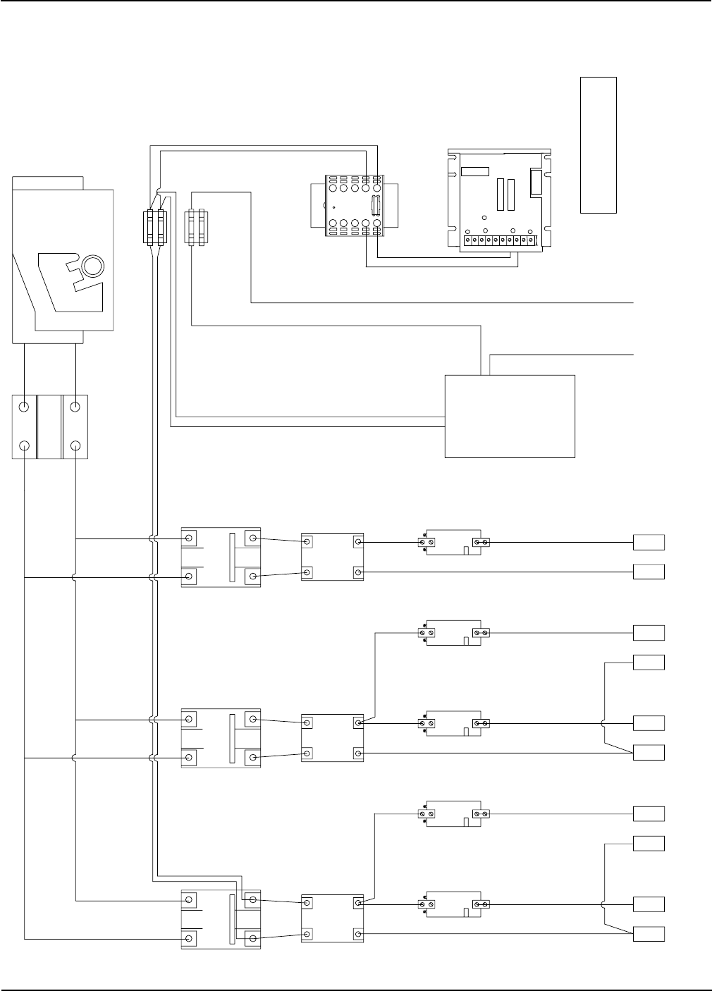
Portable Dryer Troubleshooting
66
220 Volt Single (1) Phase Power Drawing
Competitor Wiring Reference
OVERLOAD
110 VAC OUTPUT
220 VAC INPUT
J6-02 AC-1
220V FUSES
MOTOR
TO FAN #1
MOTOR
TO LOAD
MOTOR
TO AUX LOAD
MOTOR
TO UNLOAD
MOTOR
TO AUX UNLOAD
CONTACTOR
CONTACTORCONTACTOR
FAN #1
LOAD
LOAD AUX
UNLOAD
UNLOAD AUX
109
87
6
5
4
3
21
TRANSFORMER
BLOCK
DISTRIBUTION
BREAKER
MAIN
BREAKER BREAKER BREAKER
FAN #1
LOADUNLOAD
FAN #1
LOADUNLOAD
INPUT
110X0
1FI
3FI
1FO3F0
3FO
1F0
LINE
FUSE ARM
FUSE
25 AMP
8 AMP
KBIC BARRIER TERMINAL BOARD
P3 P2P1 I1 F+F- L1 L2
A+ A-
ACCEL
MIN IR CL
MAX
SCR BOARD ASSEMBLED
D03-0104
16GA BLACK
1108-1112 (1/3H.P. 240V) #D03-0039
1114-1126 (3/4H.P. 240V) #D33-0001
SCR BOARD RESISTOR VALUES
SCR BOARD
RESISTOR
SCR
CONTACTOR
L2
L1
OVERLOAD
OVERLOAD
OVERLOAD
OVERLOAD
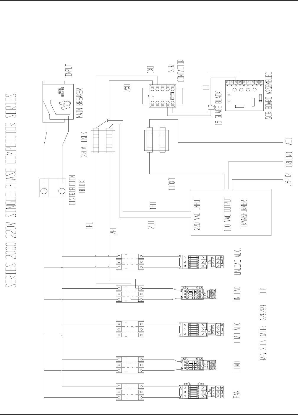
Portable Dryer Troubleshooting
67
220 Volt Single (1) Phase Power Drawing (New Version)
Competitor Wiring Reference
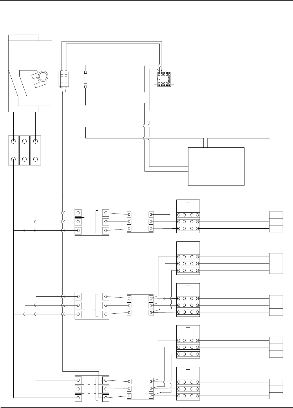
Portable Dryer Troubleshooting
68
110X0
AC1
3FO 1FO
120V FUSES
110 VAC OUTPUT
220 VAC INPUT
AC NEUTRAL AC-1
220V FUSES
CONTACTOR
SCR
TRANSFORMER
MOTOR
TO FAN #1
MOTOR
TO LOAD
MOTOR
TO AUX LOAD
MOTOR
TO UNLOAD
MOTOR
TO AUX UNLOAD
OVERLOAD
OVERLOAD
OVERLOAD
OVERLOAD
OVERLOAD
CONTACTOR
CONTACTORCONTACTOR
FAN #1
LOAD
LOAD AUX
UNLOAD
UNLOAD AUX
15
1413
12
1110
987
6
5
4
321
BLOCK
DISTRIBUTION
BREAKER
MAIN
BREAKER LOAD BREAKER FAN 1 BREAKER
UNLOAD
FAN #1
LOADUNLOAD
220 Volt Three (3) Phase Power Drawing
Competitor Wiring Reference
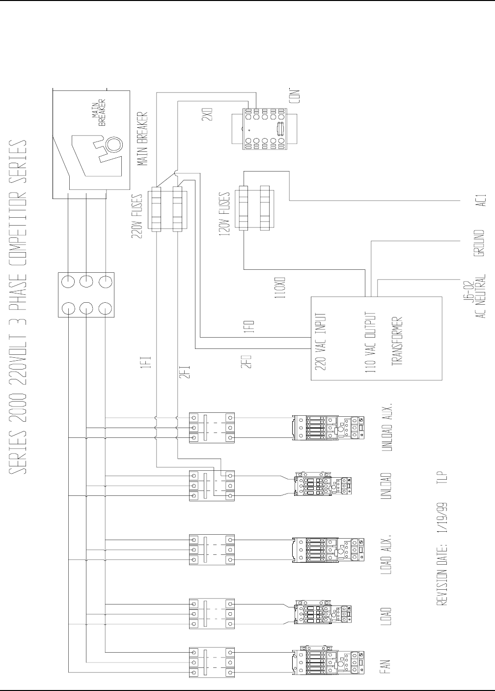
Portable Dryer Troubleshooting
69
220 Volt Three (3) Phase Power Drawing (New Version)
Competitor Wiring Reference
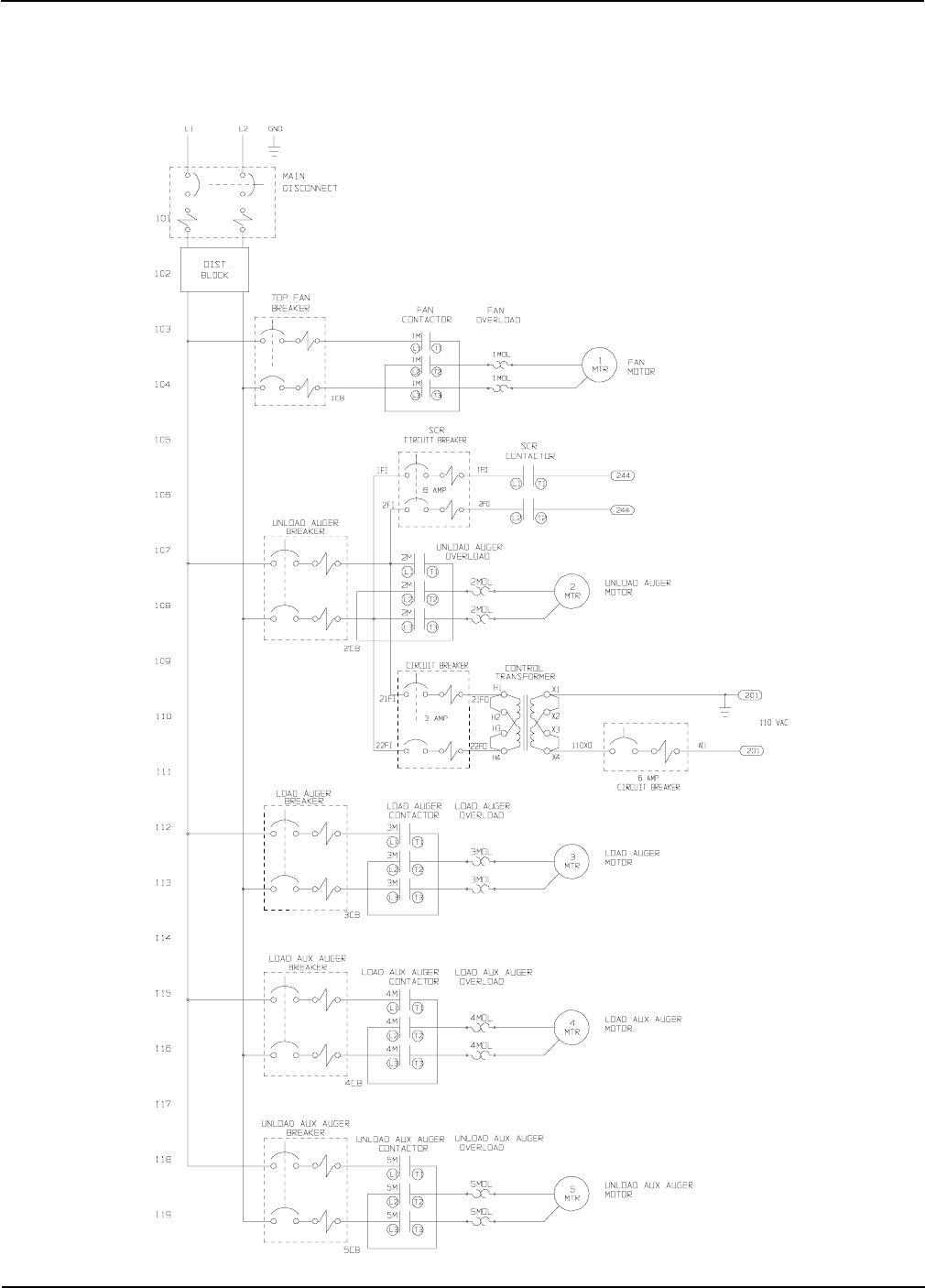
Portable Dryer Troubleshooting
70
COMPETITOR POWER CIRCUIT
( 220 VOLT 1PH )
Competitor Wiring Reference
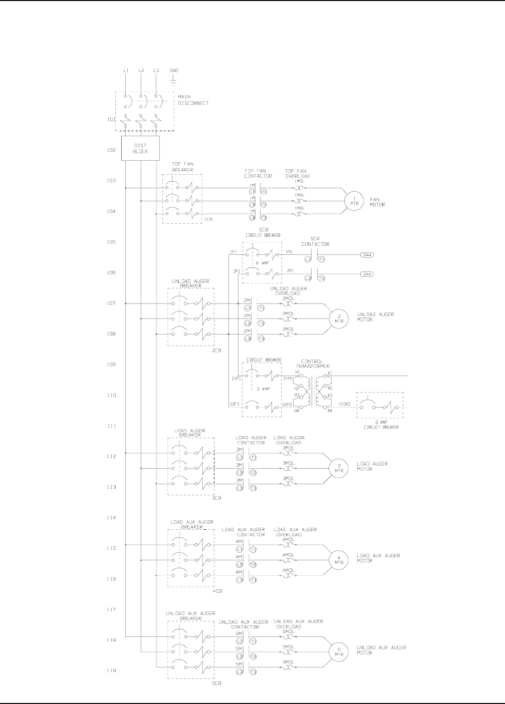
Portable Dryer Troubleshooting
71
COMPETITOR POWER CIRCUIT
( 220 VOLT 3PH )
Competitor Wiring Reference
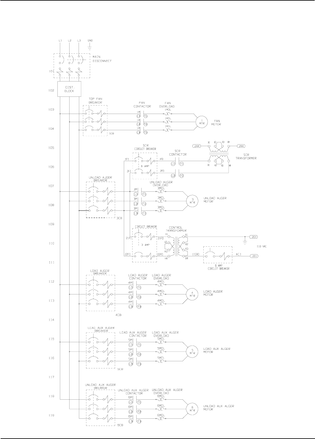
Portable Dryer Troubleshooting
72
COMPETITOR POWER CIRCUIT
( 440 VOLT 3PH )
Competitor Wiring Reference

Portable Dryer Troubleshooting
73
Upper Control Box Internal Wiring
AC1
L1
L2
J6-02
3FO
1FO
110XO
AC1
3FI
1FI
35
49
YEL
YEL
ORG
ORG COM
N/O
N/C
N/C
COM
N/O
YEL
LOAD N/O
USER INSTALLED
YELLOAD COM
USER INSTALLED
ORG
UNLD N/O
USER INSTALLED
ORG
UNLD COM
USER INSTALLED
(CANADA ONLY)
J1-16
MERCOID SWITCH
BLK
MAXON POWER
J3-04
WHT
MAXON NEUTRAL
J3-03
W
O
CONTACTOR
SCR
SCR CONT POWER
SCR CONT NEUTRAL
J6-09
J3-18
RIGHT GRAIN HI NONE
J7-08
J6-12 (BLK)
WHT
BLK
BLK
WHT
WORK LIGHT PWR LITE
WORK LIGHT NEUT J6-18
USER SAFETY
+12 VDC
HOUSE HI LIMIT
VAPOR HI LIMIT
+12 VDC
LEFT GRAIN HI
PLENUM HI LIMIT
+12 VDC
REAR DISCHARGE
+12 VDC
OUT OF GRAIN
+12 VDC
MOTOR OVERLOAD
AIRSWITCH N.O.
AIRSWITCH COM.
AIRSWITCH N.C.
FLAME DETECT
FLAME DETECT
PLENUM TEMP
GRAIN/PLENUM
GRAIN TEMP
120 AC NEUTRAL
120 AC POWER
MAIN SOL NEUT
MAIN SOL PWR
WHT
J6-02
ORGJ7-14
WHT
J7-13
YELJ7-12
A-
A+
PUR
BLK
WHT
RED
J7-02
M-SOL
SCR2
FAN POWER
FAN NEUTRAL
J4-01
J4-02
J6-07
SCR P3
SCR P2
SCR P1
IGNITION POWER
IGNITION NEUTRAL
LOAD POWER
LOAD NEUTRAL
UNLOAD POWER
UNLOAD NEUTRAL
CYCLE SOL PWR
CYCLE SOL NEUT
J6-06
J6-03
J3-14
J3-11
J3-12
J3-01
J3-02
J6-14
J6-15
BLK
GRY
GRY
BLU
WHT
BLU
RED
RED
RED
RED
RED
RED
RED
RED
J6-13
NONE
AC 1
J7-20
J7-05
J7-11
J7-19
J7-10
J7-09
J7-04
J7-03
J7-01
J1-13
J1-17
FAN #1
TRANSFORMER
UPPER STRIP
TERMINAL ON
BLOCK
DISTRIBUTION
BREAKER
MAIN
DRIVE
SCR
OVERLOADOVERLOADOVERLOAD
LOAD AUX.UNLOAD AUX.
FAN #1LOADUNLOAD
BREAKER BREAKER BREAKER
FAN #1 LOADUNLOAD
LOADUNLOAD
RR
RRR
R
R
R
R
R
J6-03
J3-14
WHT
BLU
J3-12
J3-11
WHT
YEL
OR
J3-02
J3-01
WHT
OR
P
P
P
BLK
WHT
BLU
W
Y
W
OR
W
F-
F+
L1
L2
A+
A-
3
2
1
Competitor Wiring Reference
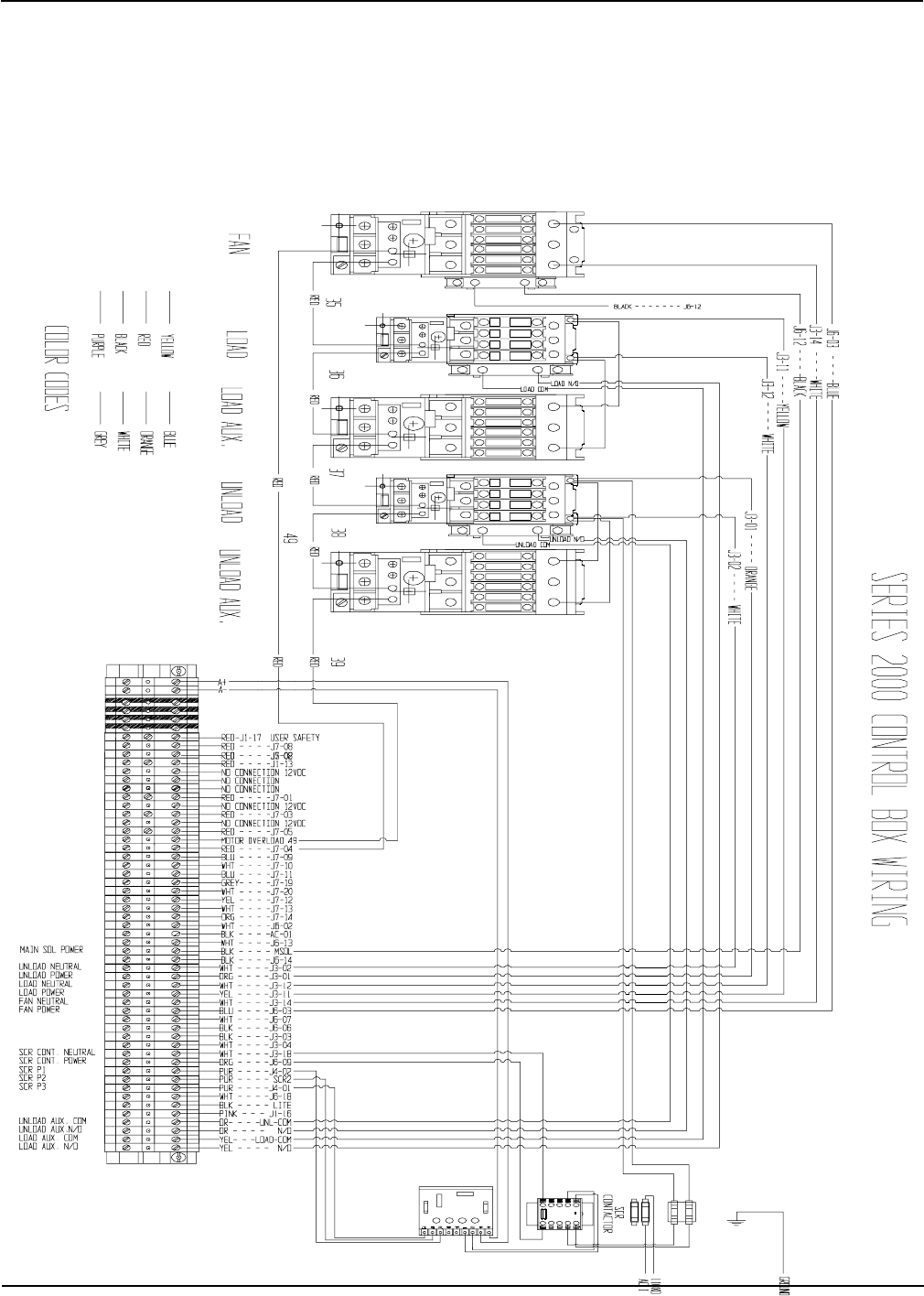
Portable Dryer Troubleshooting
74
Series 2000 Control Box Wiring (New Version)
Competitor Wiring Reference
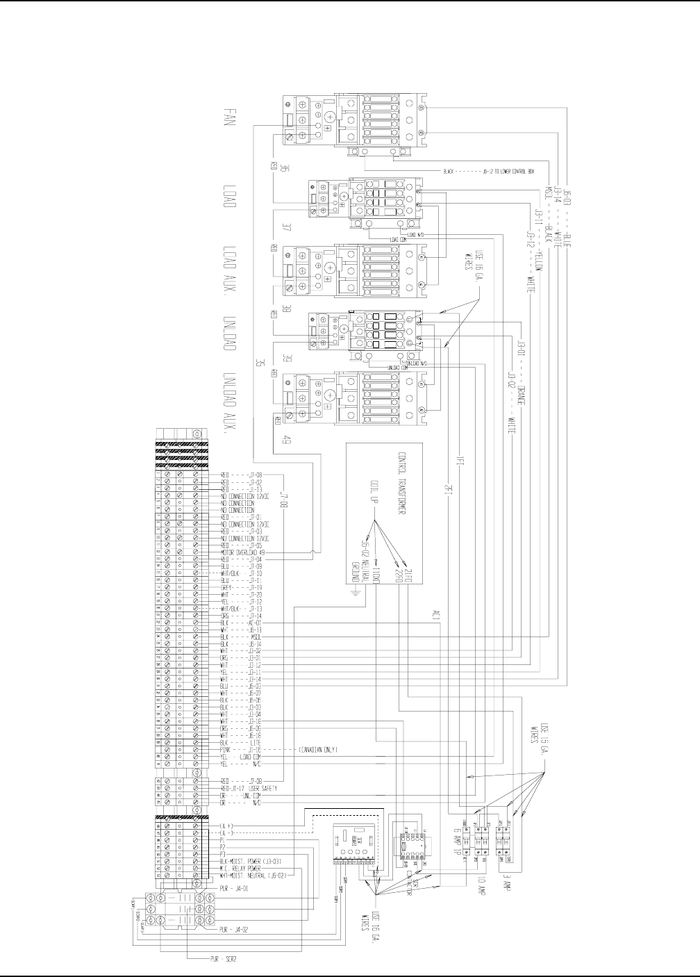
Portable Dryer Troubleshooting
75
Upper Control Box Wiring
220 Volt 1PH
Competitor Wiring Reference
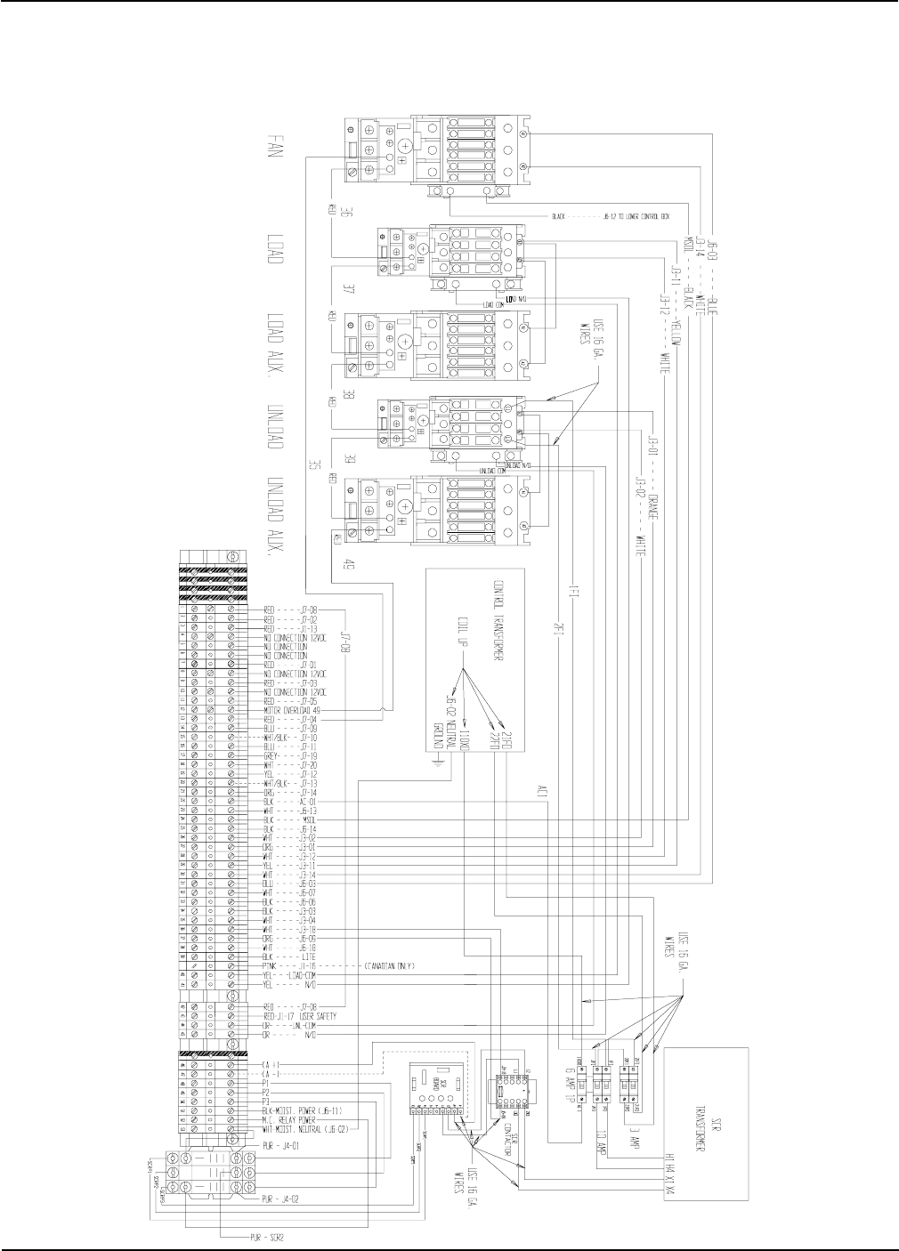
Portable Dryer Troubleshooting
76
Upper Control Box Wiring
380, 460 & 575 3PH
Competitor Wiring Reference
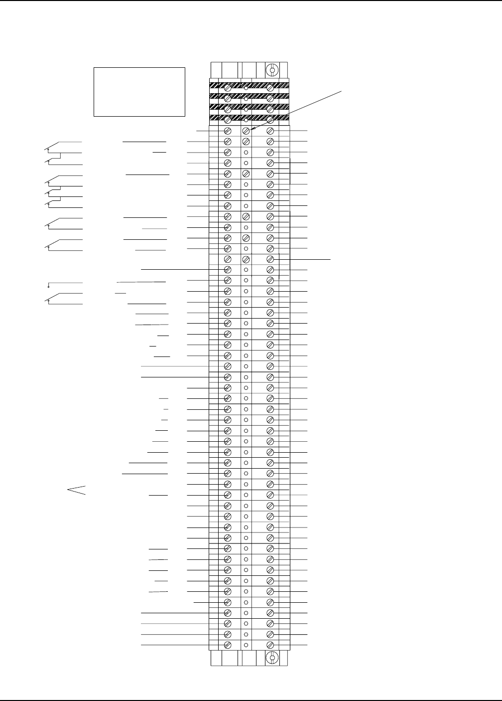
Portable Dryer Troubleshooting
77
Competitor Wiring Reference
Series 100 Control Box Wiring
100STRIP98.PRT REV. DATE 3/12/98
1 - END PROTECTOR# D01-0532
48 - COMPRESSION TERM.# D01-0531
2 - ENDSTOP# D01-0533
4 - GROUND TERMINAL# D01-0534
13" DIN RAIL# D03-0013
+12 VOLTS
HOUSING HIGH LIMIT
VAPOR HIGH LIMIT
REAR DISCHARGE
OUT OF GRAIN
AIRFLOW
AIR GND
FLAME DETECT
FLAME DETECT
PLENUM TEMPERATURE
GRAIN/PLENUM GND
GRAIN TEMPERATURE
MAIN SOLENOID NEUTRAL
MAIN SOLENOID POWER
CYCLE SOLENOID POWER
UNLOAD AUGER NEUTRAL
UNLOAD AUGER POWER
LOAD AUGER NEUTRAL
LOAD AUGER POWER
FAN POWER
FAN NEUTRAL
IGNITION NEUTRAL------
IGNITION POWER
+12 VOLTS
+12 VOLTS
RED
RED
BLK
YEL
- - PURP
ORG
ORG
WHT
BLK
BLUE
YEL
WHT/BLK
BLK
-WHT
BLK
WHT
WHT
WHT
BLK
BLK
BRN
BLK
BLK
WHT
2 WIRES WHT/BLK
+12 VOLTS
BRN
LEFT GRAIN HI- 2 WIRES ORG
PLENUM HIGH LIMIT - -BLUE
RED - - - -J7-02
NO AIRFLOW GRY
NO CONNECTION
WORK LIGHT NEUTRAL
WORK LIGHT POWER WHT
RED
METERING ROLL POT BLK
METERING ROLL POT BLK
METERING ROLL POT BLK
RIGHT GRAIN HI 2 WIRES RED NO CONNECTION
RED - - - -J7-08
RED - - - -J1-13
RED - - - -J7-03
RED - - - -J7-05
(MOTOR OVERLOAD-49)
RED - - - -J7-04 (MOTOR OVERLOAD-35)
BLUE- - - -J7-09
WHT - - - -J7-10
BLUE- - - -J7-11
GREY- - - -J7-19
WHT - - - -J7-20
YEL - - - -J7-12
WHT - - - -J7-13
RED - - - -J7-01
ORG - - - -J7-14
WHT - - - -J6-02
BLK - - - -AC-01
WHT - - - -J6-13
BLK - - - -M-SOL
BLK - - - -J6-14
WHT - - - -J3-02
ORG - - - -J3-01
WHT - - - -J3-12
YEL - - - -J3-11
WHT - - - -J3-14
BLUE- - - -J6-03
WHT - - - -J6-07
BLK - - - -J6-06
WHT - - - -J3-18
ORG - - - -J6-09
PUR - - - -J4-02
PUR - - - - SCR2
PUR - - - -J4-01
WHT - - - -J6-18
BLK - - - - LITE
ORG - UNLOAD AUX COM
ORG - UNLOAD AUX N/O
YEL - LOAD AUX COM
YEL - LOAD AUX N/O
NO CONNECTION (12 VDC CENTER TAP)
NO CONNECTION (12 VDC CENTER TAP)
NO CONNECTION (12 VDC CENTER TAP)
NO CONNECTION (12 VDC CNTR TAP)
NO CONNECTION
NO CONNECTION
NO CONNECTION
SCR CONTACTOR NEUTRAL
SCR CONTACTOR POWER - WHT
ORG
USER INSTALLED
USER INSTALLED
USER INSTALLED
USER INSTALLED
2 WIRES -
2 WIRES -
MERCOID SWITCH (CANADA ONLY) PINK------------ J1-16
MAXON NEUTRAL -------- WHT WHT - - - -J3-04
MAXON POWER ---------- PUR BLK - - - -J3-03
16 GA WIRES
RED - - - -J1-17 USER SAFETY
NO CONNECTION (12VDC CNTR TAP)
REMOVE SCREW TO ACTIVATE
USER SAFETY TERMINAL
CONNECT WIRE FROM J7-08
THRU USER SAFETY SWITCH
BACK TO USER SAFETY TERM.
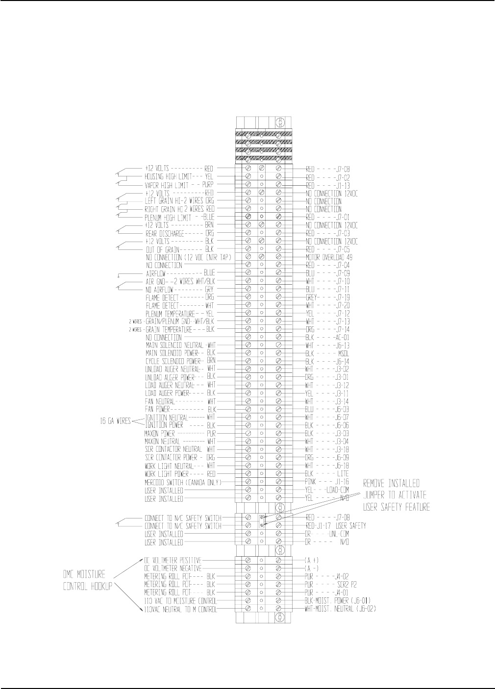
Portable Dryer Troubleshooting
78
Upper Terminal Strip
With Moisture Control Hook Up
Competitor Wiring Reference
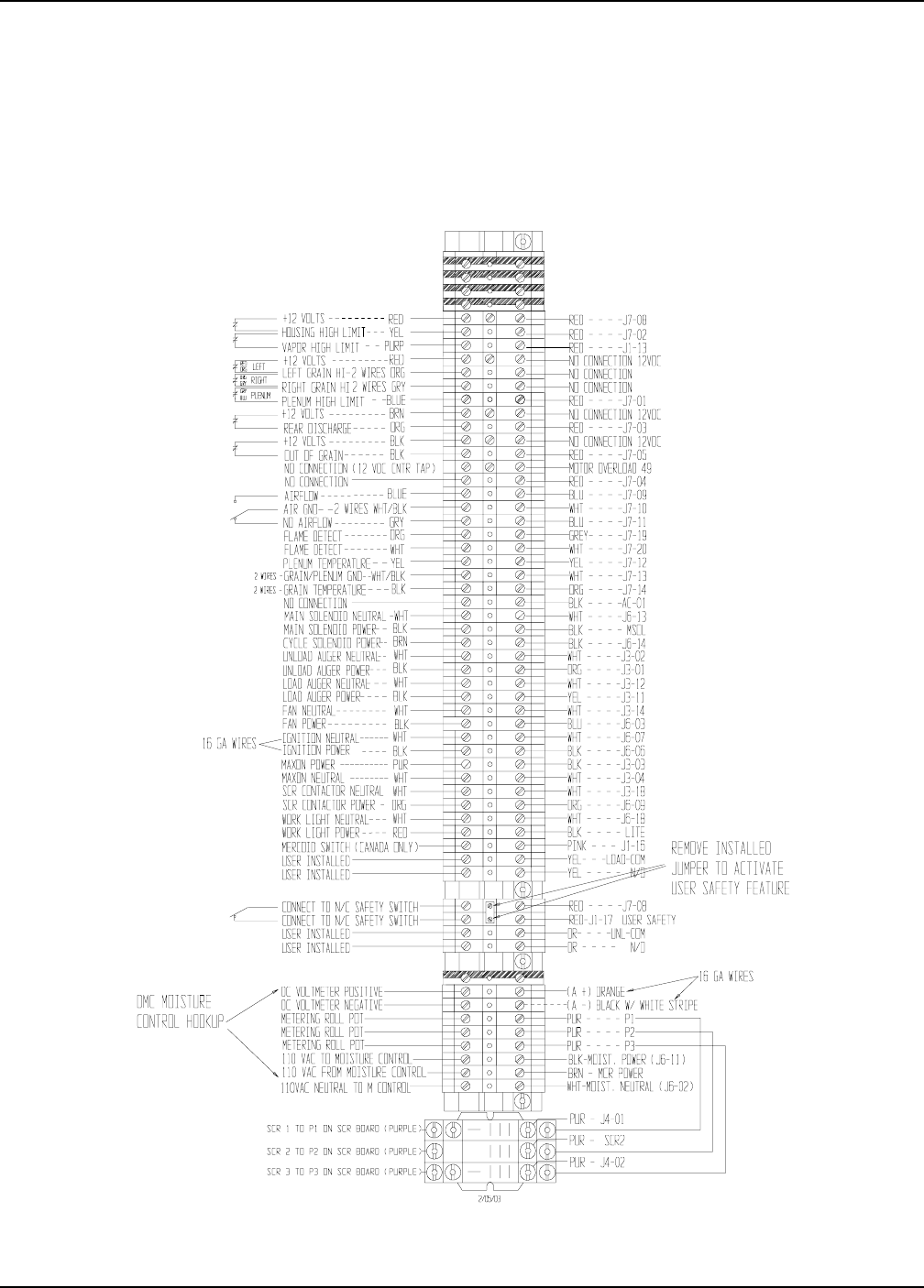
Portable Dryer Troubleshooting
79
Upper Terminal Strip
With Moisture Control Relay Hook Up
Competitor Wiring Reference
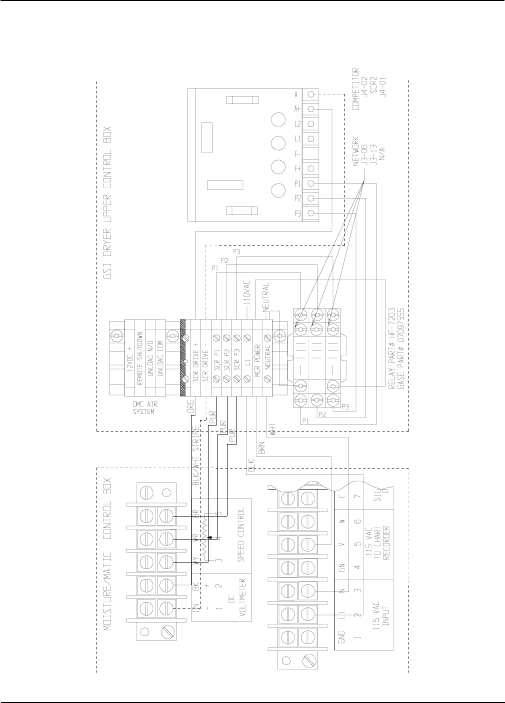
Portable Dryer Troubleshooting
80
Moisture Manager to Dryer Wiring
(Upper Control Box)
Competitor Wiring Reference
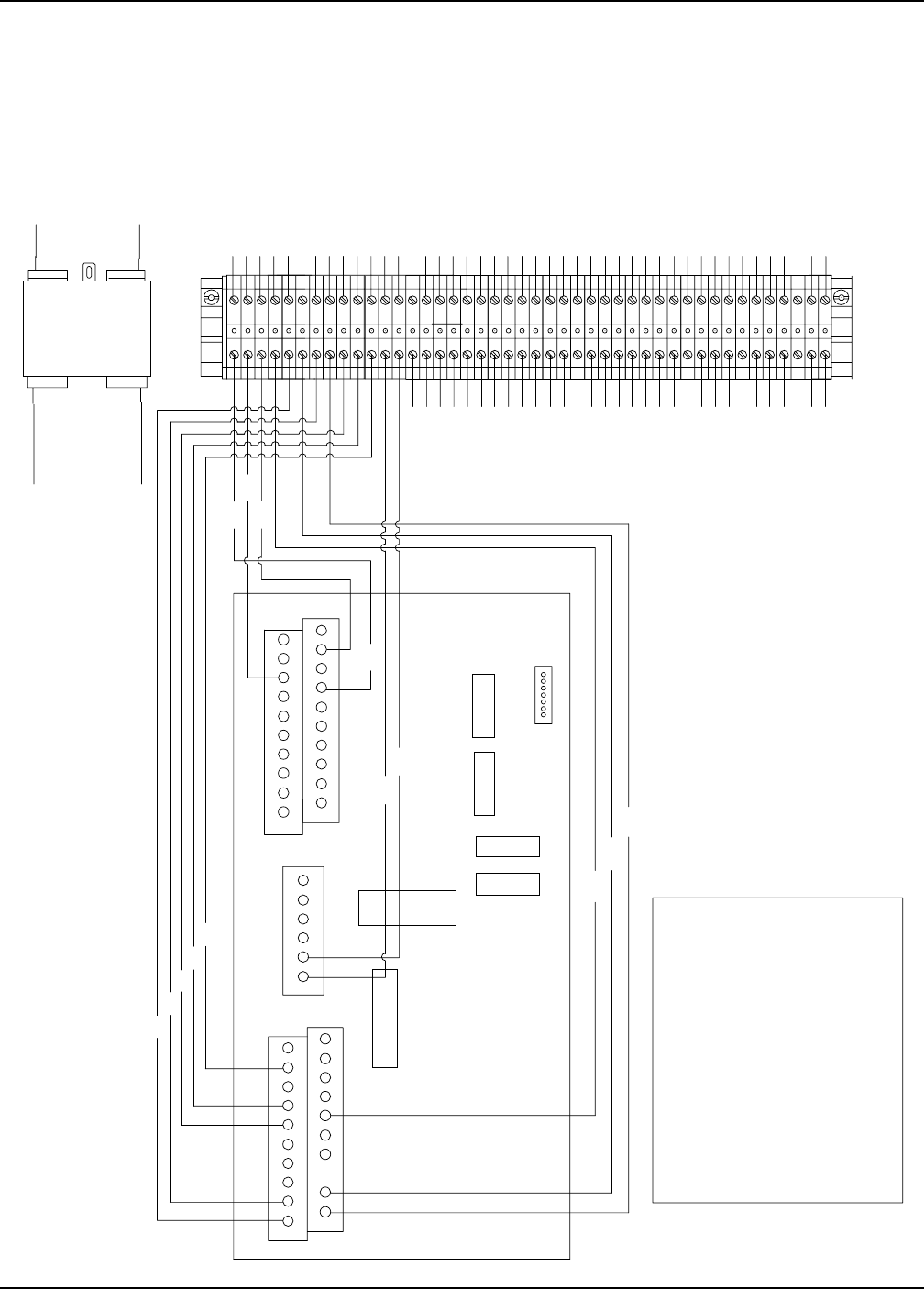
Portable Dryer Troubleshooting
81
Input/Output Board & Terminal Strip
PUR
PUR
RED
RED --- J1-17
PUR --- SCR2
BLK --- LITE
PUR --- J4-01
PUR --- J4-02
PNK
RED
RED --- J1-13
YEL
BLK
ORG
RED
WHT
WHT
WHT
WHT
WHT
WHT --- J3-04
BLK --- J3-03
WHT --- J3-18
BLUE-3
BLACK-4
WHITE-6
RED-6
YELLOW-1
ORANGE-2
GREY-1
WHT/BLK-2
WIRES
TO DOOR:
RED-2
ORANGE-1
WHITE-5
YELLOW-1
BLACK-1
PURPLE-2
TO I/O BOARD:
J6-02
J6-1
3 AMP FUSE
J2
J4
21
20
19
J1
21
20 19
J3
BLK --- J6-06
RED --- J7-03
ORG --- J3-01
PNK --- J1-16 - - CANADIAN MODELS ONLY
WHT --- J7-20
GRY --- J7-19
ORG --- J7-14
WHT/BLK J7-13
YEL --- J7-12
BLU --- J7-11
WHT/BLK J7-10
BLU --- J7-09
RED --- J7-08
RED --- J7-05
RED --- J7-04
RED --- J7-02
RED --- J7-01
WHT --- J6-18
WHT --- J6-15
BLK --- J6-14
WHT --- J6-13
BLK --- J6-12
ORG --- J6-09
WHT --- J6-07
BLU --- J6-03
WHT --- J3-14
WHT --- J3-12
YEL --- J3-11
WHT --- J3-02
J6-02
AC1
EMI FILTER
D03-0181
LOAD
LINE
5VB1
CORCOM
Competitor Wiring Reference
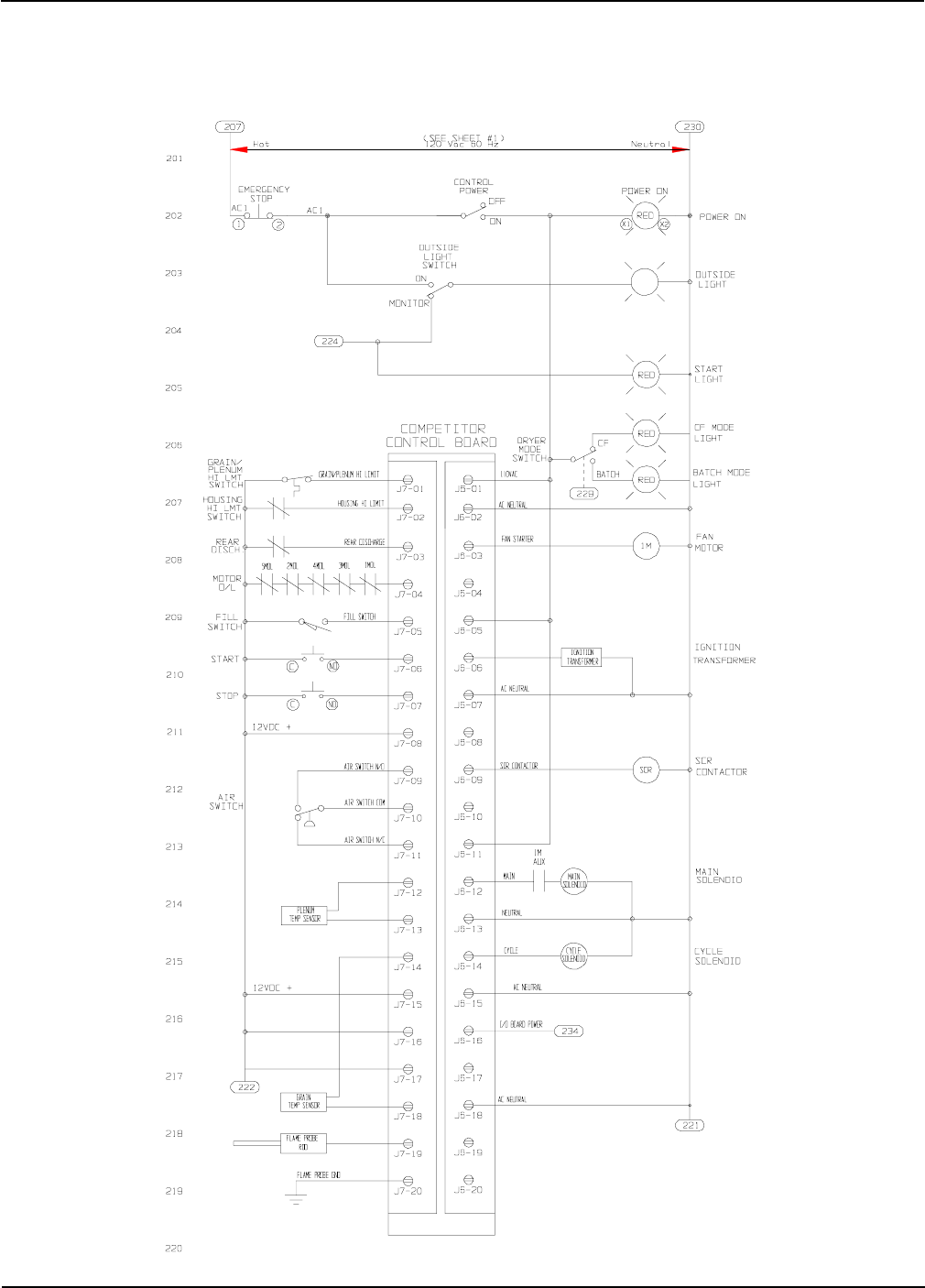
Portable Dryer Troubleshooting
82
Competitor Control Circuit
CPU/Display Board
Competitor Wiring Reference
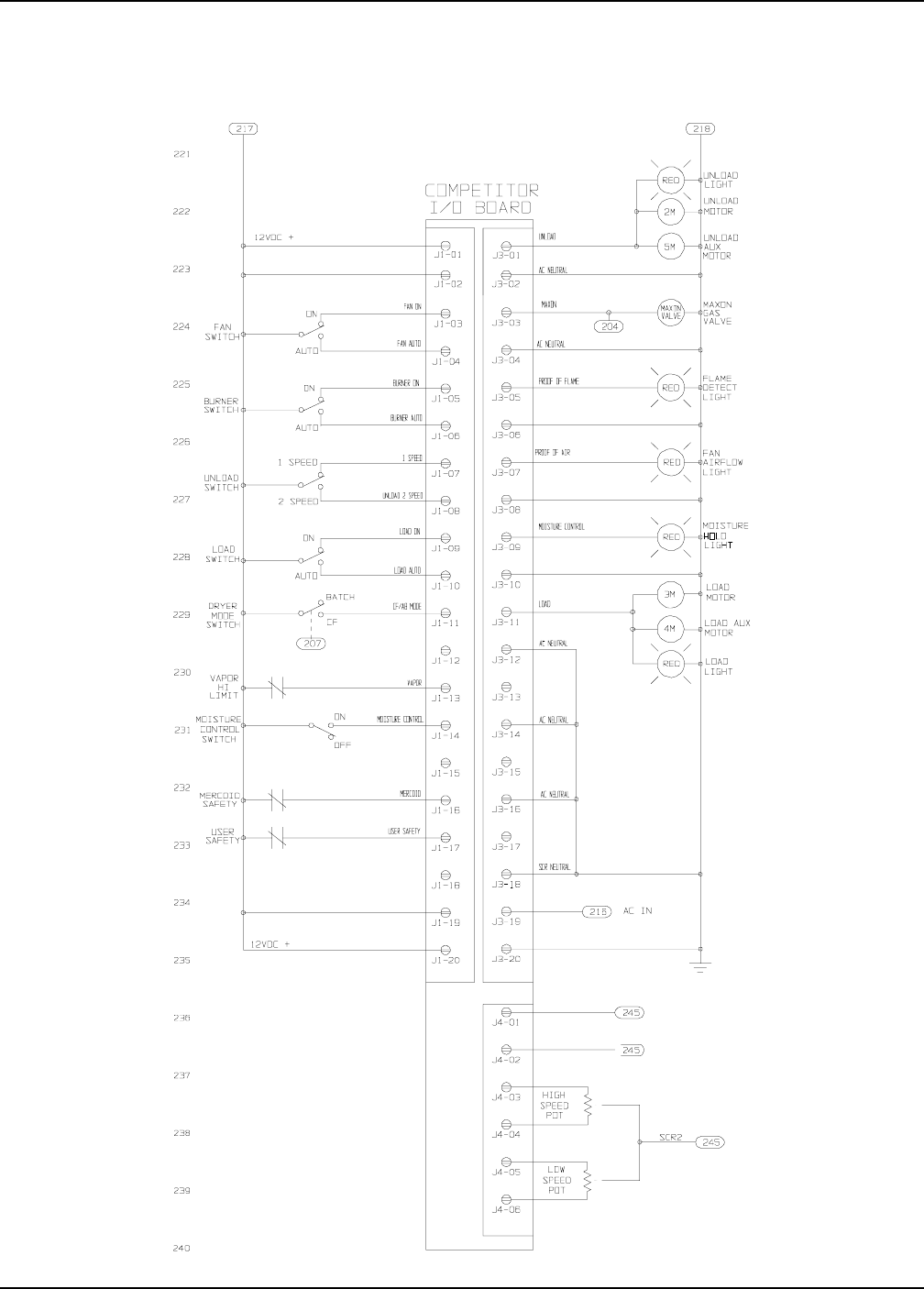
Portable Dryer Troubleshooting
83
Competitor Control Circuit
I/O Board
Competitor Wiring Reference
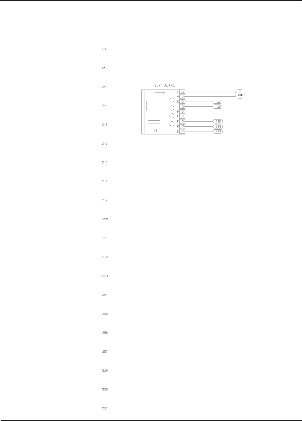
Portable Dryer Troubleshooting
84
Competitor Control Circuit
SCR Drive Board
Competitor Wiring Reference
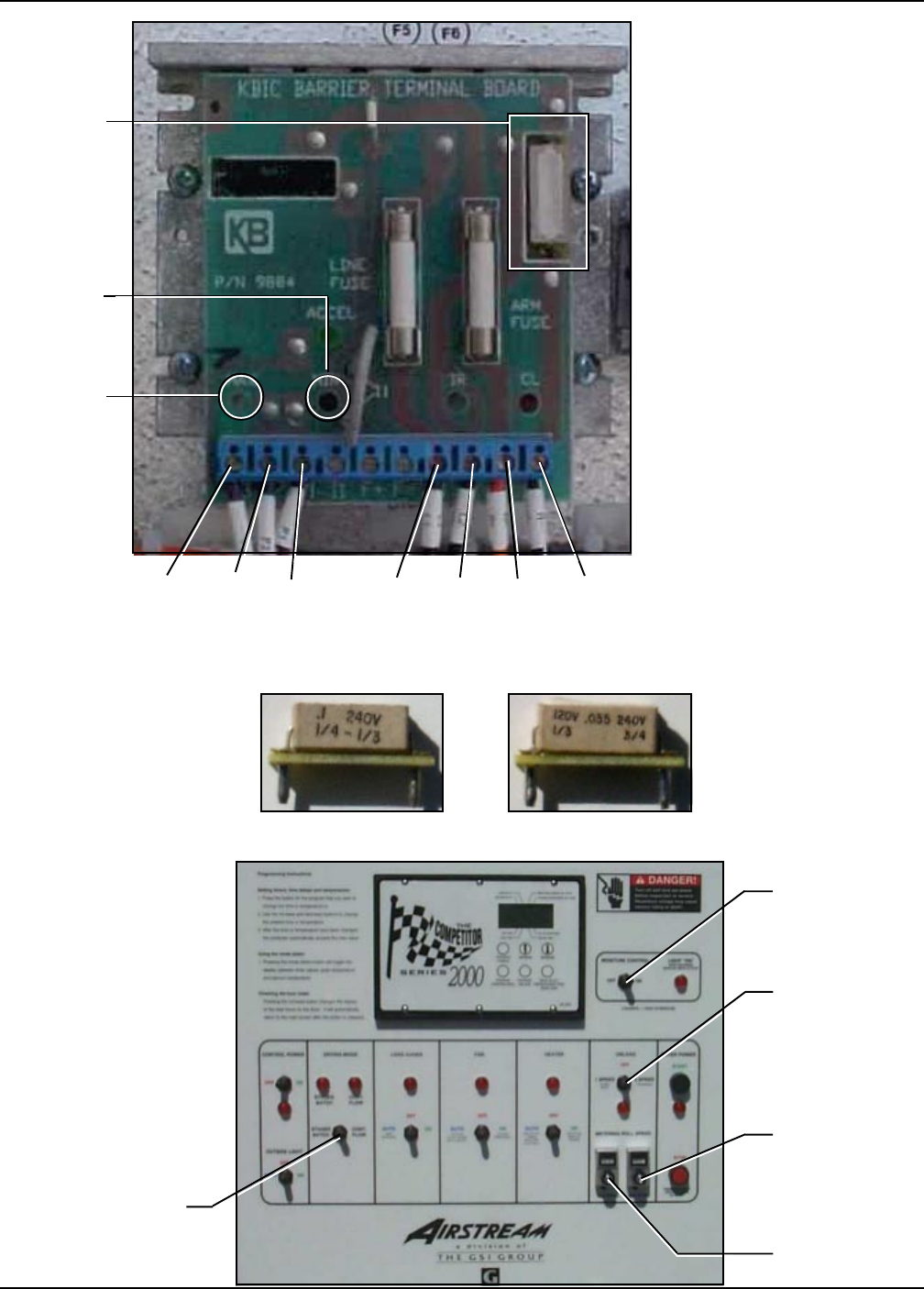
Portable Dryer Troubleshooting
85
P3 P2 P1 L1 L2 A-A+
MIN
MAX
* The SCR board is located in the
upper control box.
* Terminals L1 and L2 are the input
terminals. When the unload system
is turned on there should be 220
Volts AC accross these terminals.
* Terminals A+ and A- are the ouput
terminals. The voltage across these
terminals is DC and will vary de-
pending on where the speed con-
trol potentiometer is set.
* The item circled at the bottom right
of the SCR board in the photograph
is the minimum set potentiometer.
This will be used in the SCR board
set up to set minimum DC voltage.
* The item circled at the bottom left
of the SCR board in the photograph
is the maximum set potentiometer.
This will be used in the SCR board
set up to set maximum DC voltage.
Unload
Switch
Drying Mode
Switch
Metering Roll
Speed (High)
Metering Roll
Speed (Low)
Control panel switch locations.
Moisture
Control
Switch
IMPORTANT: After the new board has been installed be sure to remove the resistor
(shown in the photograph above) from the old board and install it in the new board. Just
pull the resistor from the two pin socket and install in the same socket on the new board.
Resistor for 1/3 Hp
Meter Roll motors
used on 12 ft dryers
and shorter. (part
no. D03-0039)
Resistor for 3/4 Hp
Meter Roll motors
used on 14 ft dryers
and longer. (part
no. D33-0001)
RESISTOR
Competitor Wiring Reference
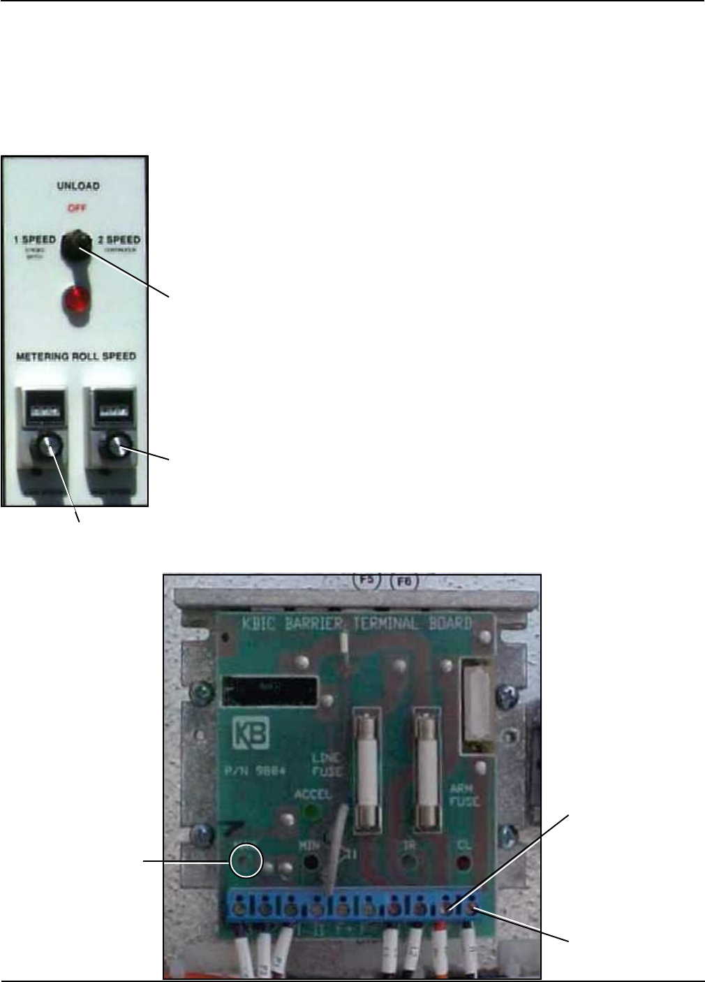
Portable Dryer Troubleshooting
86
A-
A+
MAX
Before starting the procedure set the dryer up as follows:
1. All fan and heater switches to off position and load switch to off position.
2. Control power to on position.
3. Push the dryer power switch.
4. Dryer mode switch to cont. flow position.
5. Moisture control switch to on position.
6. Unload switch to 2 speed position.
Unload
Switch to 2
speed
position
Metering Roll
Speed (High) set to
999
Metering Roll
Speed (Low) set to
050
1. Set the low metering roll speed to 050 on the dial
indicator shown in the photograph on the left. Set the
high metering roll speed to 999.
2. Switch the Unload switch to the 2 speed position.
3. Switch the Moisture Control switch to the off position.
This will put the meter roll rotation speed to the high
setting.
4. Use a voltmeter set at the 200 volt DC range and
probe terminal A+ with the red voltmeter probe and A-
with the black voltmeter probe. If the display on your
voltmeter reads 180 volts DC no maximum adjustment
is needed. If your voltmeter does not read 180 VDC,
then use a small screw driver and adjust the max set
petentiometer until the voltage is 180 VDC.
Setting SCR Board Maximum Voltage
Competitor Wiring Reference
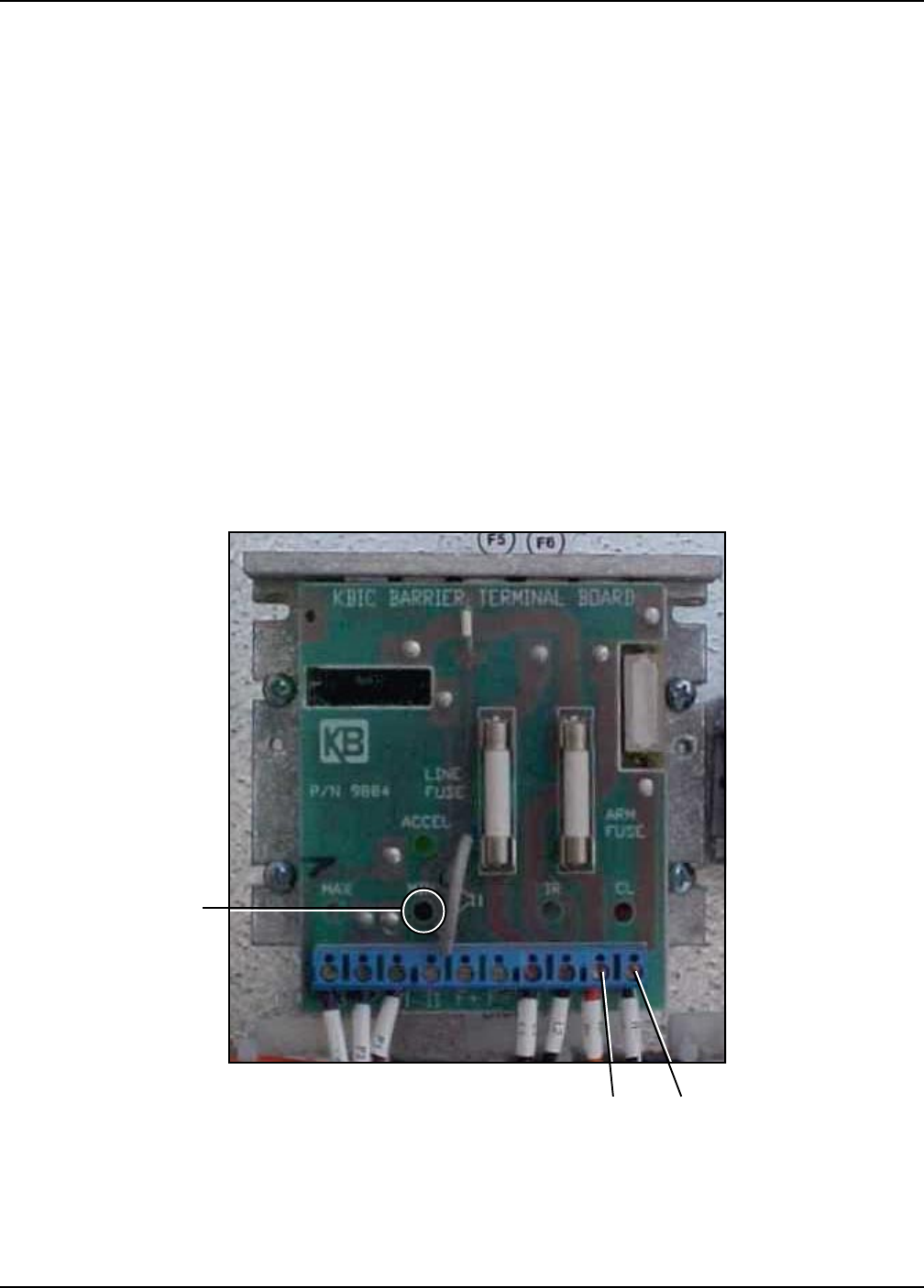
Portable Dryer Troubleshooting
87
A-A+
MIN
Setting SCR Board Minimum Voltage
1. Switch the Moisture Control Switch back to the on position. This will put the meter roll rotation
speed at the low setting.
2. Use a voltmeter set at the 20 volt DC range and probe terminal A+ with the red voltmeter probe
and A- with the black voltmeter probe. Use a small screw driver and adjust the min set potentiom-
eter until the voltage is 9 VDC.
The SCR board is now set and dryer is ready for normal operation at desired settings.
SCR Drive Board (Part No. D03-0104)
Competitor Wiring Reference
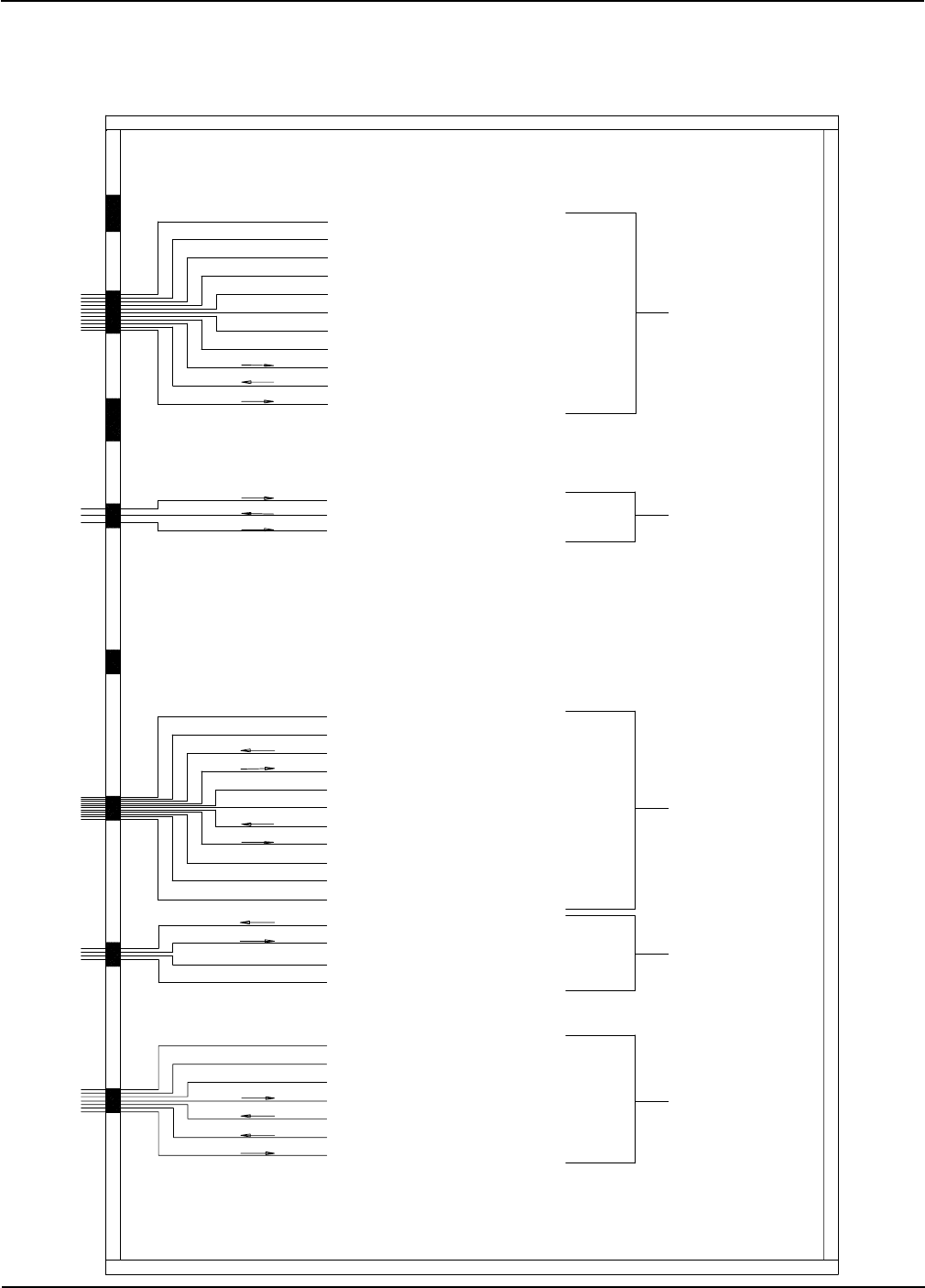
Portable Dryer Troubleshooting
88
Upper Control Box External Wiring
TO FAN CONTROL BOX
TO AIRSWITCH ASSEMBLY
TO LOWER JUNCTION BOX
TO UPPER JUNCTION BOX
TO PLENUM AND RIGHT
FIXED GRAIN HIGH LIMIT
SWITCHES AND TEMPERATURE
SENSORS
WHITE/BLACK STRIP J7-10 12VDC NEGATIVE
PURPLE J7-13 FROM VAPOR HIGH LIMIT SWITCH
RED J7-08 12VDC INPUT POWER TO HOUSING & VAPOR HIGH LIMIT SWITCHES
YELLOW J7-02 FROM HOUSING HIGH LIMIT SWITCH
BROWN J6-14 CYCLE SOLENOID 120VAC POWER
WHITE J6-13 MAIN/CYCLE SOLENOID 120VAC NEUTRAL
BLACK J6-12 MAIN SOLENOID 120VAC POWER
BLACK J6-06 IGNITION TRANSFORMER 120VAC POWER 16 GA. WIRE
WHITE J6-07 IGNITION TRANSFORMER 120VAC NEUTRAL 16 GA. WIRE
WHITE J7-20 FLAME DETECTION TO FLAME PROBE BASE
ORANGE J7-19 FLAME DETECTION TO FLAME PROBE
GREY J7-11 CONNECTS TO AIRSWITCH N.C. TERMINAL
WHITE/BLACK STRIP J7-10 CONNECTS TO AIRSWITCH COMMON TERMINAL
BLUE J7-09 CONNECTS TO AIRSWITCH N.O. TERMINAL
GREEN 16 GA. SCR DRIVE MOTOR GROUND
BLACK 16 GA. A- SCR DRIVE MOTOR
RED 16 GA. A+ SCR DRIVE MOTOR
ORANGE J7-03 FROM REAR DISCHARGE SWITCH
BROWN 12VDC TO REAR DISCHARGE SWITCH
WHITE J3-04 MAXON 120VAC NEUTRAL (NATURAL GAS ONLY)
PURPLE J3-03 MAXON POWER 120VAC (NATURAL GAS ONLY)
ORANGE 12VDC FROM LEFT GRAIN HIGH LIMIT SWITCH
RED 12VDC TO LEFT GRAIN HIGH LIMIT SWITCH
BLACK J7-14 RIGHT GRAIN TEMPERATURE SENSOR
WHITE J7-13 PLENUM/GRAIN TEMPERATURE SENSOR COMMON
RED LITE 120VAC OUTSIDE LIGHT POWER
WHITE J6-18 OUTSIDE LIGHT AC NEUTRAL
BLACK J7-05 FROM LOAD MERCURY SWITCH
BLACK 12VDC TO LOAD MERCURY SWITCH
RED FROM RIGHT GRAIN HIGH LIMIT SWITCH
ORANGE TO RIGHT GRAIN HIGH LIMIT SWITCH
RED TO PLENUM HIGH LIMIT SWITCH
BLUE FROM PLENUM HIGH LIMIT SWITCH TO J7-01
BLACK J7-14 GRAIN TEMPERATURE SENSOR
WHITE J7-13 PLENUM/GRAIN TEMPERATURE SENSOR COMMON
YELLOW J7-12 PLENUM TEMPERATURE SENSOR
Competitor Wiring Reference
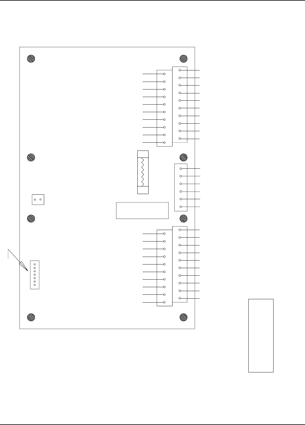
Portable Dryer Troubleshooting
89
Input/Output Board 12 Volt
THESE JUMPERS MUST BE INSTALLED
J1-1 TO J1-17 - USER SAFETY
J1-1 TO J1-16 - MERCOID SAFETY
AC NEUTRAL
RL1-A N.O. HIGH SPEED POT B
RL1-A N.C. LOW SPEED POT B
RL1-B N.O. HIGH SPEED POT A
RL1-B N.C. LOW SPEED POT A
RL1-B COMMON TO POT INPUT ON SCR BOARD
RL1-A COMMON TO POT INPUT ON SCR BOARD
R
E
L
A
Y
120 VOLT AC OUTPUT
12 VOLT DC INPUT
DATA INTERLINK CABLE CONNECTION
AC NEUTRAL
120V INPUT FROM CPU
AC NEUTRAL
N.C. (TIED TO J3-19)
N.C. (TIED TO J3-19)
FAN NEUTRAL
TRIAC SPARE
LOAD AUGER NEUTRAL
LOAD POWER
AC NEUTRAL
MOISTURE CONTROL HOLDING LIGHT
AC NEUTRAL
PROOF OF AIRFLOW LIGHT
AC NEUTRAL
PROOF OF FLAME LIGHT
AC NEUTRAL
MAXON VALVE/DRYER RUNNING LIGHT
UNLOAD AUGER POWER UNLOAD AUGER NEUTRAL
2
4
68
101214161820
19 17 15 13 11 9 7 531
12 VDC
12 VDC
SPARE
USER SAFETY INPUT
MERCOID SAFETY INPUT
SPARE
MOISTURE CONTROL ON
VAPOR HIGH LIMIT INPUT
DRYER EMPTY (BATCH ONLY)
CONTINUOUS FLOW
LOAD AUTO
LOAD ON
UNLOAD 2 SPEED
UNLOAD 1 SPEED
BURNER AUTO
BURNER ON
FAN AUTO
FAN ON
12 VDC 12 VDC
3 AMP FUSE
2
4
68
101214161820
19 17 15 13 11 9 7 531
J4 J3
J1
J2 J5
Competitor Wiring Reference
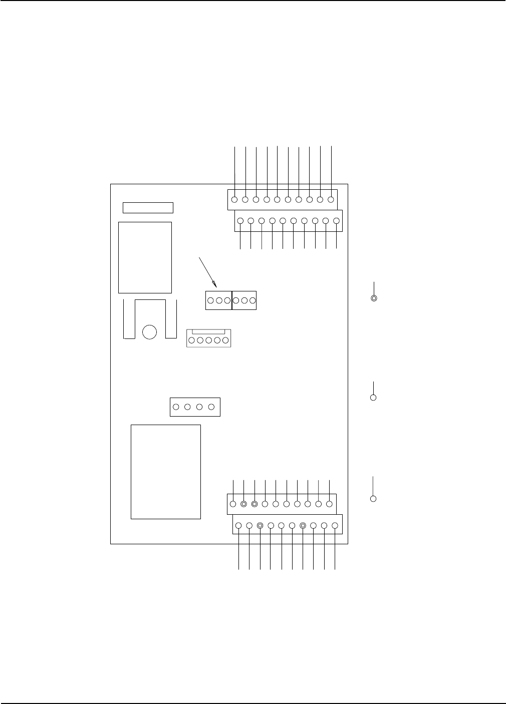
Portable Dryer Troubleshooting
90
12 VDC GROUND
-
-
-
-
MOTOR OVERLOAD
PLENUM TEMP SENSOR
OUT OF GRAIN SWITCH
STOP SWITCH
START SWITCH
12VDC NEGATIVE
FLAME PROBE B FLAME PROBE A
+12VDC OUTPUT
AC NEUTRAL SPARE AC OUTPUT
LIGHT AC NEUTRAL
RL1 N.O.
RL3 N.C.
NO CONNECTION
RL3 N.O. SCR DRIVE OUT
RL3 COM SCR IN
120VAC TO I/O BOARD
110V NEUTRAL
N
18
16
14
12
10
8
6
4
19
17
15
13
11
9
7
5
3
2
1
20
IGN TRANS PWR 120VAC
MAIN SOL PWR 120VAC
CYCLE SOL PWR 120VAC
LOAD COIL NEUTRAL
MAIN SOL NEUTRAL
CYCLE SOL NEUTRAL
IGN TRAN NEUTRAL
110VAC IN RL1 N.C.
AC NEUTRAL INPUT
N
N
N
N
N
N
N
RS485 COM PORTS
+ 12VDC OUTPUT
GRAIN TEMP SENSOR
AIRSWITCH COM (DC NEG)
HOUSING HI-LIM
+ 12VDC OUTPUT
TEMP SENSOR (GROUND)
+ 12VDC OUTPUT
REAR DISCHARGE SWITCH
GRAIN/PLENUM HIGH LIMIT SWITCH
N/O AIRSWITCH (5 VDC)
N/C AIRSWITCH (5 VDC)
18
16
14
12
10
8
6
4
19
17
15
13
11
9
7
5
3
21
J7
20
4
1
J5
3
3
1
1
J1
J8
J6
FUSE
TRANSFORMER
MONITORING
DISPLAY
RL1 COMMON
J2
Cpu Board Wiring
Competitor Wiring Reference

Portable Dryer Troubleshooting
91
Programing Instructions for Competitor Series Grain Dryers
Competitor Wiring Reference
1. Turn Control Power on dryer to the off position.
2. Locate programming jack (J2) on back of computer. (See next page). There will be a cable plugged into
this jack that comes from the other computer board. Unplug this cable to plug the programmer into the jack.
3. Plug the series 2000 cable into programming jack and into programmers DB-9 jack.
4. Be sure that the rotary switch on the programmer is set to position 8.
5. Turn on Control Power to the dryer.
6. The four (4) lights on the programmer will come on, then three (3) will go out leaving the power light still on.
7. Push the start button on the programmer to start the transfer of Software.
8. The busy light will flash until the transfer process is complete.
9. When completed, the pass light will flash indicating a successful transfer.
10. If the fail light flashes then check your connections and repeat the above process.
11. Turn Control Power on dryer to off and remove the cable.
12. Turn on the dryer and the opening screens should indicate the newer version of software.
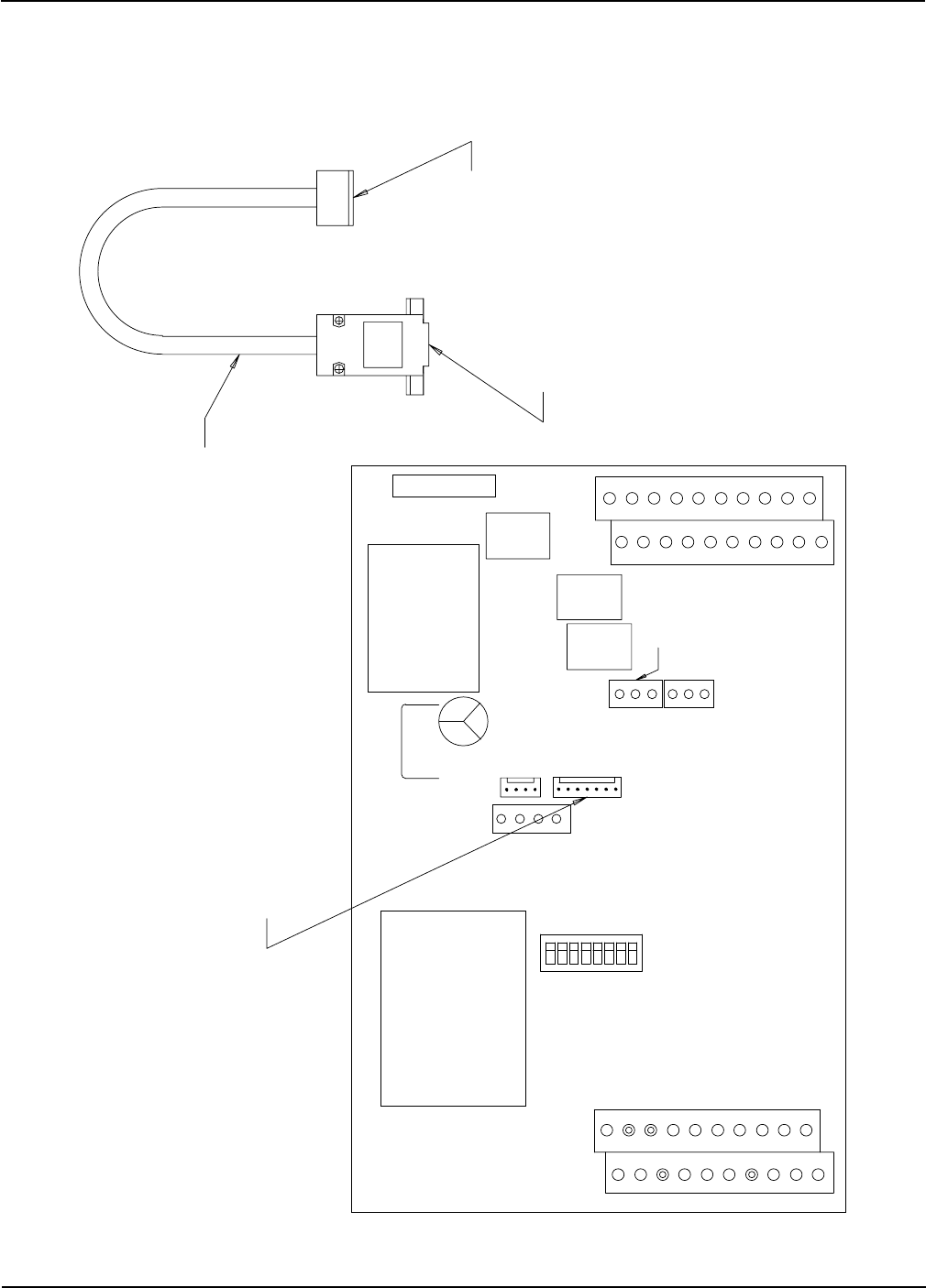
Portable Dryer Troubleshooting
92
Programmer Hook Up Diagram
DB9 JACK
PLUG THIS INTO
THE PROGRAMMER
J2 CONNECTOR
SERIES 2000 CABLE
PROGRAMMING JACK TO UPDATE
SOFTWARE ON EPROM PLUG
PROGRAMMER INTO THIS JACK
RS485
COM
PORTS
J4
J5
J2
ON
87654321
DIP SWITCH #6 = BURNER CYCLE HI-LO (OFF) OR ON-OFF (ON)
DIP SWITCH #5 = NO LOAD DURING LOW FIRE CYCLE (BATCH ONLY)
DIP SWITCH #7 = EMERGENCY COOLING MODE
DIP SWITCH #8 = AIR SWITCH TEST ON OR OFF
DIP SWITCHS
MONITORING
DISPLAY
TRANSFORMER
FUSE
J6
J8
J1 1
1
3
3
1
4
20
J7
1
2
3
5
7
9
11
13
15
17
19
4
6
8
10
12
14
16
18
N
N
N
N
N
N
N
20
12
3
5
7
9
11
13
15
17
19
4
6
8
10
12
14
16
18
-
-
-
Competitor Wiring Reference

Portable Dryer Troubleshooting
93
Competitor Wiring Reference
Programming Instructions Using Palm Pilot
On the Competitor Dryer there is only one board to program. This board is called the CPU
Display board. It is mounted to the door of the lower box. To access, open the door and the pro-
gramming jack is located on the back of this board. To program, follow the instructions below.
1. Turn the control power on the dryer to the off position.
2. Locate the programming jack (J2 connector) on back of board.
3. Unplug the communications cable that is connected to that connector. This is the cable that
runs from the CPU/Display board and IO Board.
4. Connect the DB-9 connector from the Palm Pilot to the series 2000 cable.
5. On the Palm Pilot select the program for that particular board and tap on it.
6. Turn the dryer control power back on.
7. The programming process should begin, it will erase the present program and start the new
program.
8. A screen will come up telling you when the transfer of software is complete.
9. When the process is complete turn dryer control power off, remove the connector from the
board and plug the communications cable back on to the CPU/Display board.
10. Turn on the dryer and the opening screens should indicate the latest version of software.
Refer to next page for more information on programming the Series 2000 board.
If ordering Palm Pilot from GSI there are two kits available:
D03-0692 ( Palm Flash Program Kit Deluxe )
D01-1771 Series 2000 Programming Cable
D03-0688 Palm Pilot IIIC (color)
D03-0694 Palm Pilot Hot Sync Cable
D03-0695 Palm Flash 9 Pin M-M Adapter
D03-0709 Disk, CD-Rom Palm Flash Software
D03-0693 ( Palm Flash Program Kit Economy )
D01-1771 Series 2000 Programming Cable
D03-0689 Palm Pilot M100 (black & white)
D03-0695 Palm Flash 9 Pin M-M Adapter
D03-0709 Disk, CD-Rom Palm Flash Software
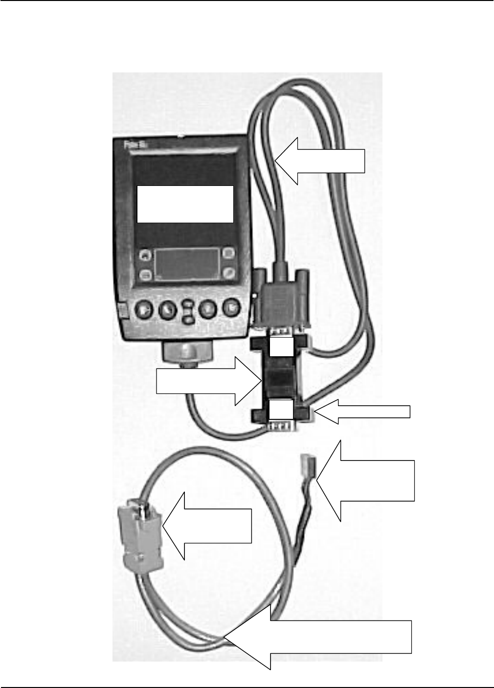
Portable Dryer Troubleshooting
94
Programming Competitor Dryer Using Palm Pilot
Palm Pilot
D03-0689 (M100)
D03- 0688 ( IIIC)
Hot Sync Cable
D03-0694
DB-9 M-M Adapter
D03-0695
J2 Connector
(Connects to the back
of CPU/Display board)
DB-9 Connector
Palm
Side
D ryer
Side
DB-9 Connector
(Connects to the
DB-9 M-M adapter)
Series 2000 Programming Cable
D01-1771
(Use on CPU/Board)
Programming Competitor
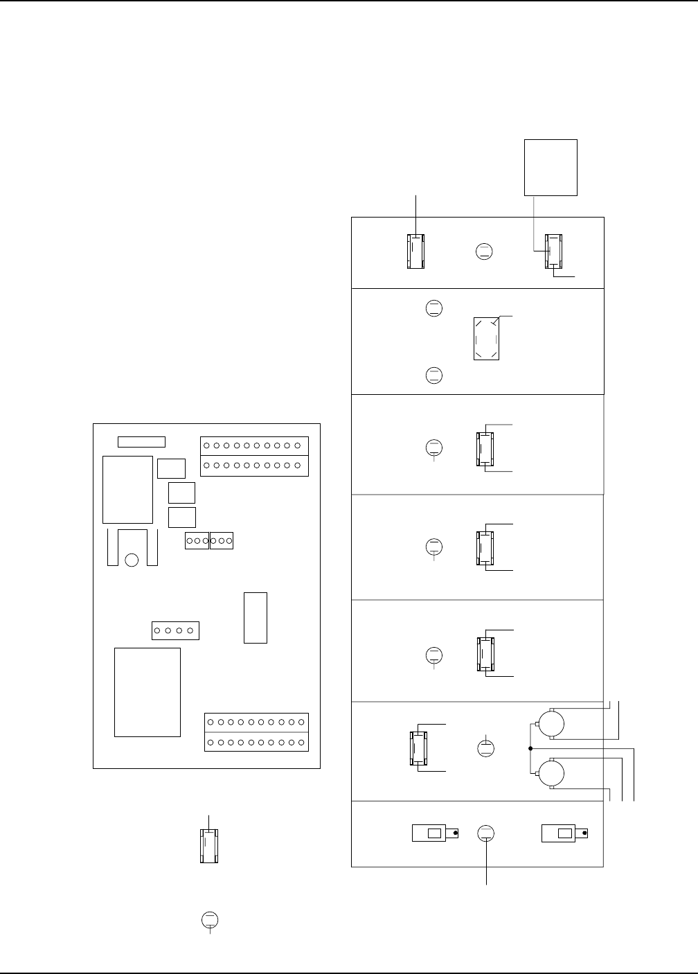
Portable Dryer Troubleshooting
95
Back of Switch Panel Layout
MONITORING
DISPLAY
TRANSFORMER
FUSE
J6
19 20
12
J8
J6
1
1
3
3
J5
1
4
1
2
1920
J7
START
STOP METERING ROLL SPEED
CONTROL POWER
OUTSIDE LIGHT
DRYING MODE
BATCHCF
com
no
com
no
LITE
CONNECTS TO
TERMINAL STRIP
ON BACK PANEL
J1-11
J1-09J1-10
J3-11
J3-07
J1-04 J1-03
J3-01
J3-05
J1-08
J1-07
J4-03
J4-05
J4-06
J4-04
SCR-2
J3-03
J1-06 J1-05
BMBM
T
T
MOISTURE CONTROL
J1-14
J3-09
CONNECT J6-05
TO J6-01.
AC1
THREE POS
TWO POS
FROM I/O BOARD:
ORANGE-5
BLACK-1
PURPLE-4
BROWN-3
BLUE-3
YELLOW-3
GREY-1
TO DISPLAY:
BLACK-1
RED-1
WHITE-1
BLUE-1
YELLOW-1
JUMPERS:
RED J1-16 TO J1-20
RED J3-19 TO J6-16
WHITE J3-04 TO J6-17
BLACK J6-05 TO J6-11
BLACK J6-01 TO J6-05
OR OR
BK
OR OR
OR
PR
PR
PR
PR
PR
BR
BR BR
BL
BL BL
YL
YL YL
GY GY
GY
BK
BK
J3-03
BLK
UNLOAD BURNER FAN LOAD
Competitor Wiring Reference
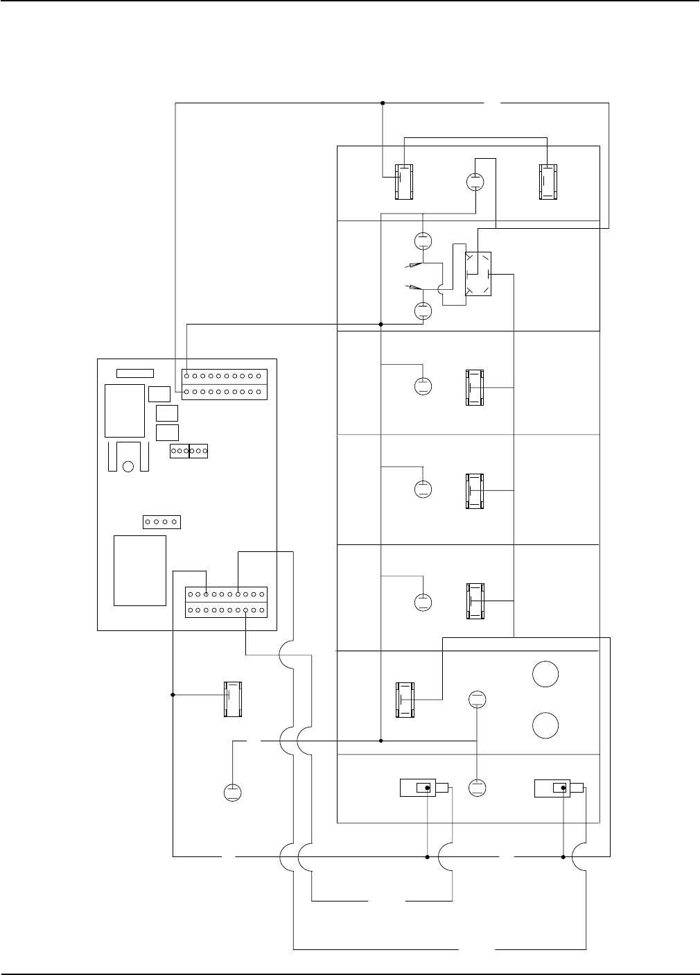
Portable Dryer Troubleshooting
96
MONITORING
DISPLAY
TRANSFORMER
FUSE
J6
19 20
12
J8
J1
1
1
3
3
J5
1
4
1
2
1920
J7
START
STOP
UNLOAD
METERING ROLL SPEED
HEATER CONTROL POWER
OUTSIDE LIGHT
DRYING MODE
LOAD AUGER
FAN
J6-02 J6-02
J6-02 J6-2 J6-02
J6-02
J6-02
J7-15
J7-15 J7-15 J7-15 J7-15
BATCHCF
com
no
com
no
J6-02 (AC NEUTRAL)
WHITE
J6-01
J6-01 (AC POWER) BLACK
REQUIRED JUMPERS:
RED J3-19 TO J6-16
WHT J3-04 TO J6-17
BLK J6-01 TO J6-05
MOISTURE CONTROL
RED
J7-07
YEL
J7-06
BLU
RED
RED
WHITE
BLACK
GREY
THREE POS
Back of Switch Panel Wiring
Competitor Wiring Reference
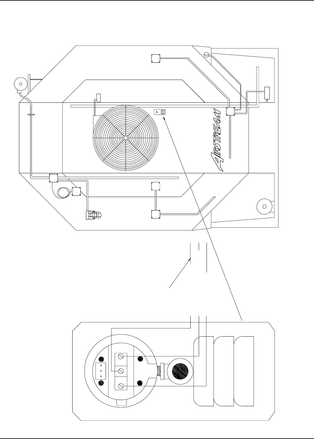
Portable Dryer Troubleshooting
97
GREY J7-11 NO AIRFLOW (N.C.)
PLENUM
SCR
UNLOAD
MOTOR
1XX
RIGHT FIXED
GRAIN HIGH
LIMIT
OUTSIDE LIGHT
TEMP. SENSORS
LOAD
MOTOR
LOAD MERCURY SWITCH
UPPER
BOX
JUNCTION
FAN
SOLENOID
AIR SWITCH
LEFT FIXED
GRAIN HIGH
LIMIT
TEMP. SENSORS
GAS PIPE TRAIN
LOWER
BOX
JUNCTION
C N.C. N.O.
CALIBRATED WITH
DIAPHRAGM VERTICAL
WHITE/BLACK STRIP J7-10 AIRFLOW GROUND
BLUE J7-09 AIRFLOW (N.O.)
TO UPPER CONTROL BOX
BACKVIEW OF AIR SWITCH ASSEMBLY
HIGH
Air Switch Assembly
Competitor Wiring Reference
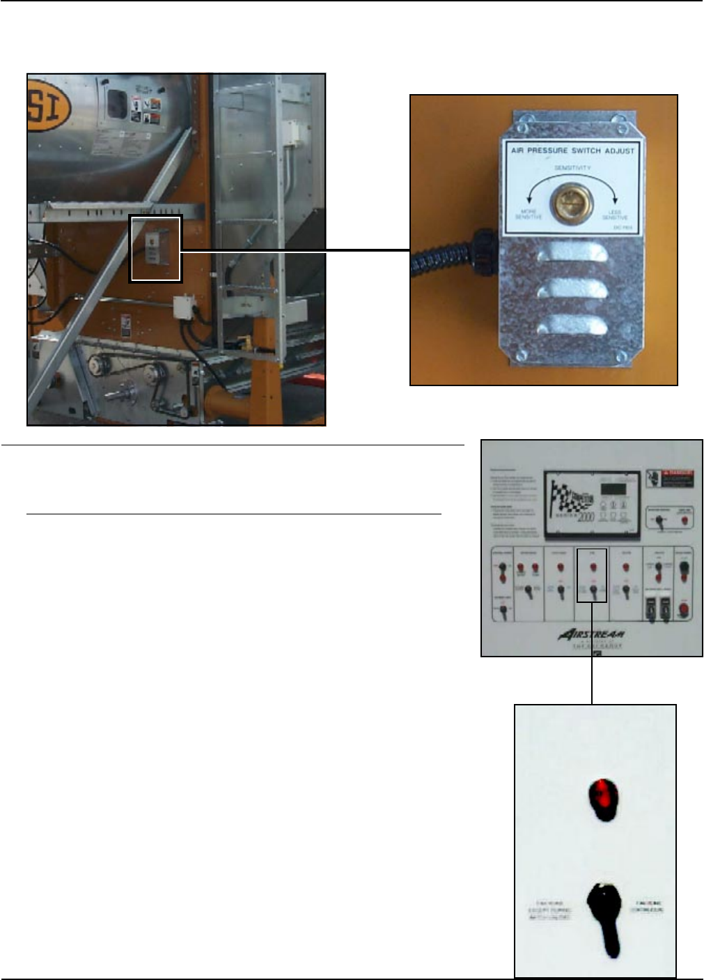
Portable Dryer Troubleshooting
98
IMPORTANT: To adjust the air switch the grain columns
need to be full of grain so that the plenum can build up air
pressure and close the air switch.
With the Load Auger, Fan, Heater, and Unload switches in the off position turn
on the Control power then push the Dryer Power Start switch.
With power now applied to the dryer flip the fan switch to the on position and
watch the light right above that switch. If the light illuminates when the fan
reaches half its full speed, then no adjustment is required. However, if the light
does not illuminate until the fan is running at full speed or the light does not
illuminate at all and the dryer shuts down the air switch is adjusted too high
(skip to step 3a). If the light illuminates before the fan reaches half its full
speed the air switch is adjusted too low (skip to step 3b).
1.
2.
3a.
Air Switch assembly.
FAN
AUTO
OFF
ON
If the light above the fan switch illuminates after the fan reaches full speed or did not
illuminate at all and the dryer shut down then the air switch needs to be made more
sensitive. Turn adjustment screw in the more sensitive direction (counter clock-
wise). Make this adjustment on the air switch 1/4 turn at a time and each time restart
the fan and watch to see when the light illuminates.
3b. If the light above the fan switch illuminates before the fan reaches half its full speed
then the air switch needs to be less sensitive. Turn adjustment screw in the less
sensitive direction (clockwise). Make this adjustment on the air switch 1/4 turn at a
time and each time restart the fan and watch to see when the light illuminates.
Air Switch location.
4. Flip the fan switch to the off position and watch the light. Now it should go out when
the fan is about half its full speed. Adjust the air switch if necessary. Remember that
less sensitive (clockwise adjustment) will require a higher fan speed to close the air
switch, and more sensitive (counter clockwise adjustment), the switch can close at
a slower fan speed.
Competitor Air Switch Adjustment
Air Switch Adjustment
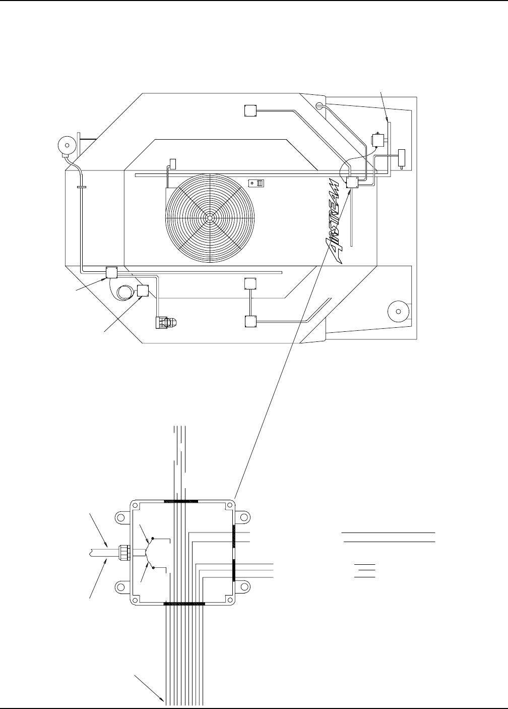
Portable Dryer Troubleshooting
99
Fixed Grain Hi-Limit & Temperature Sensor
PLENUM
SCR
UNLOAD
MOTOR
1XX
RIGHT FIXED
GRAIN HIGH
LIMIT
OUTSIDE LIGHT
TEMP.
SENSORS
LOAD
MOTOR
LOAD MERCURY
SWITCH
UPPER
BOX
JUNCTION
FAN
SOLENOID
AIR SWITCH
LEFT FIXED
GRAIN HIGH
LIMIT
TEMP. SENSORS
GAS PIPE
TRAIN
LOWER
BOX
JUNCTION
WHITE J7-13
BLACK J7-14 RED
ORANGE
BROWN FROM 12VDC TO DISCHARGE SWITCH
ORANGE FROM J7-03 TO DISCHARGE SWITCH
RED 16 GA. A+ TO SCR DRIVE MOTOR
BLACK 16 GA. A- TO SCR DRIVE MOTOR
GREEN 16 GA. TO SCR DRIVE GROUND
TO LEFT FIXED
GRAIN HIGH LIMIT
AND TEMPERATURE
SENSORS
WIRES GO TO UPPER
CONTROL BOX
TO SCR
DRIVE MOTOR
TO REAR
OF DRYER
NATURAL GAS DRYERS ONLY
MAXON
PURPLE J3-03
WHITE J3-04
BLACK TO MAXON
WHITE TO MAXON
SJOW 18/2 WIRE
Competitor Wiring Reference
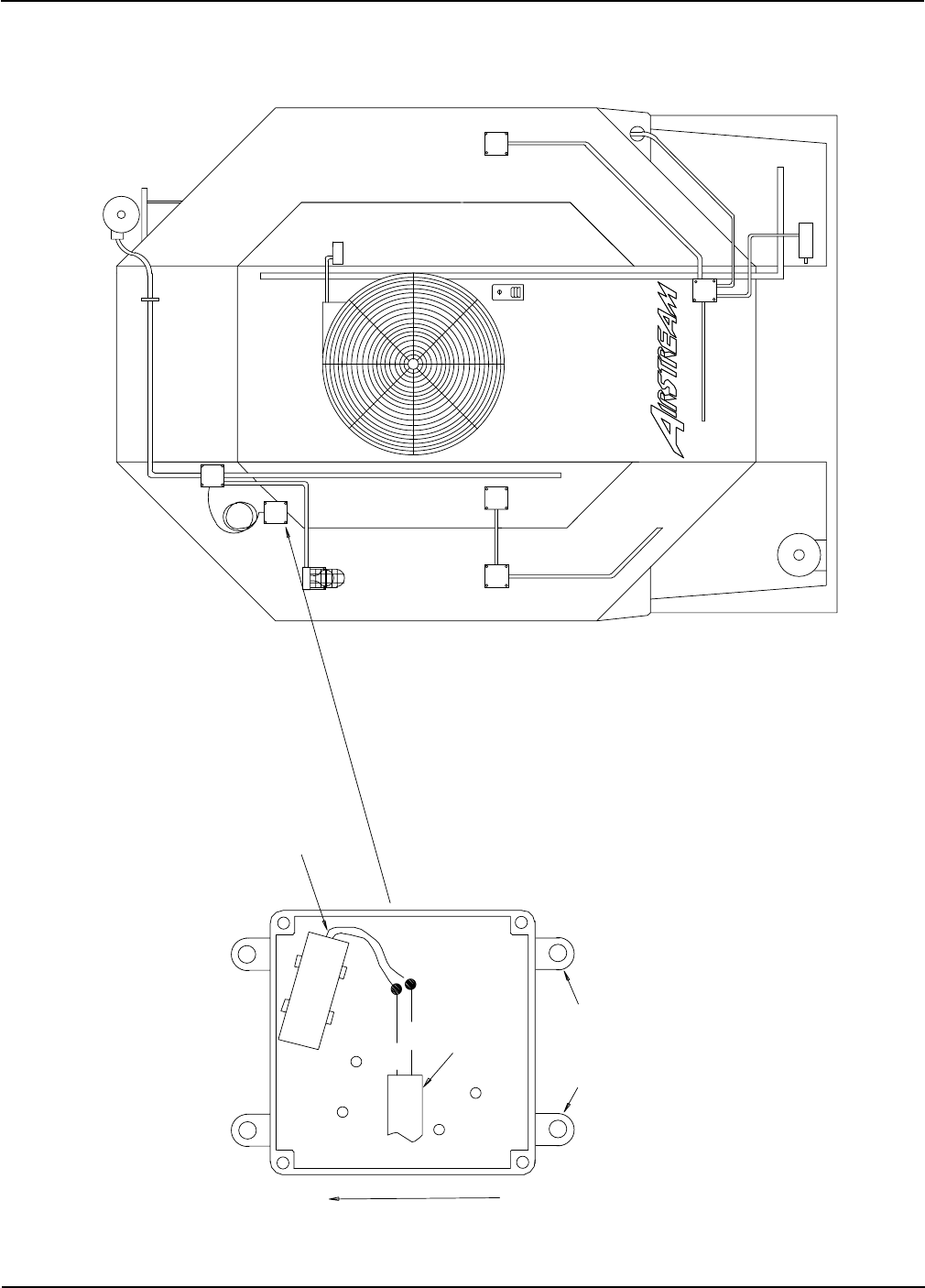
Portable Dryer Troubleshooting
100
Out of Grain Sensor
JUNCTION
BOX
LOWER
GAS PIPE TRAIN
TEMP. SENSORS
LIMIT
GRAIN HIGH
LEFT FIXED
AIR SWITCH
SOLENOID
FAN
JUNCTION
BOX
UPPER
LOAD MERCURY SWITCH
MOTOR
LOAD
TEMP. SENSORS
OUTSIDE LIGHT
LIMIT
GRAIN HIGH
RIGHT FIXED
1XX
MOTOR
UNLOAD
SCR
PLENUM
REMOVE THESE EARS
SJOW 18/2 WIRE
EXITS THROUGH
BOX COVER
BLACK
WHITE
LEADS MUST BE IN THIS POSITION
FOR PROPER OPERATION
UP
FRONT VIEW OF OPEN BOX
Competitor Wiring Reference
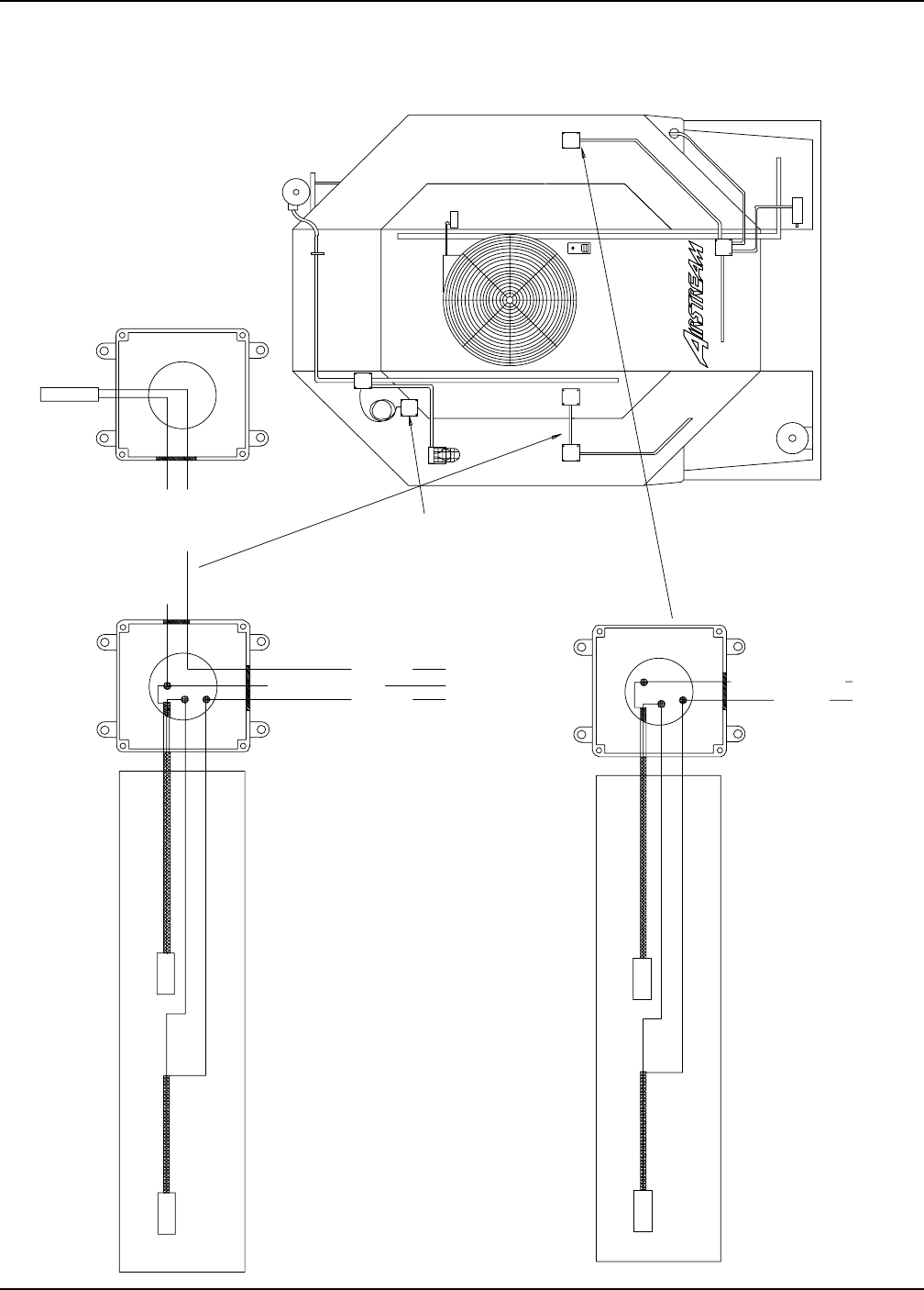
Portable Dryer Troubleshooting
101
Grain Temperature Sensor
BLACK 20 GA.
WHITE/BLACK STRIP 20 GA.
REAR FRONT
WHITE/BLACK STRIP J7-13
PLENUM TEMP SENSOR
INSIDE GRAIN COLUMN CONDUIT
TO LOWER JUNCTION BOX
BLACK 20 GA.
WHITE/BLACK STRIP 20 GA.
REAR FRONT
INSIDE GRAIN COLUMN CONDUIT
TO UPPER CONTROL BOX
CONNECT TO SHIELD OF WIRE
CENTER WIRE
CENTER WIRE
CONNECT TO SHIELD OF WIRE
YELLOW J7-12
YELLOW J7-12
WHITE/BLACK STRIP J7-13
BLACK J7-14
WHITE/BLACK STRIP J7-13
BLACK J7-14
SCR
UNLOAD
MOTOR
1XX
LOAD MERCURY
SWITCH
FAN
SOLENOID
Competitor Wiring Reference
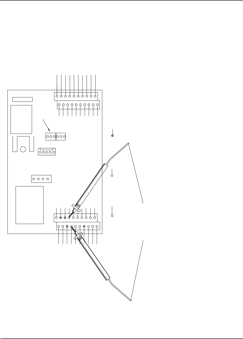
Portable Dryer Troubleshooting
102
Grain Sensor Testing
SENSORS COMP98.PRT
IF OHMS DOES NOT = 11.0 K
CHECK LOWER AND UPPER TERMINAL
STRIP (J7-13 GND & J7-14)
IF MEASUREMENTS DO NOT = 11.0 K
CHECK CONNECTIONS IN WHITE
JUNCTION BOX ON FAR LEFT AND
RIGHT SIDES FACING THE FAN END.
IF NONE OF THE MEASUREMENTS = 11.0 K,
THEN CHECK EACH INDIVIDUAL SENSOR.
USING OHM METER BEGIN CHECKING
THE SENSORS FOLLOWING FIG.1
J2
RL1 COMMON
MONITORING
DISPLAY
TRANSFORMER
FUSE
J6
J8
J1 1
1
3
3
J5
1
4
20
J7
1
2
3
5
7
9
11
13
15
17
19
4
6
8
10
12
14
16
18
N/C AIRSWITCH (5 VDC)
N/O AIRSWITCH (5 VDC)
GRAIN/PLENUM HIGH LIMIT SWITCH
REAR DISCHARGE SWITCH
+ 12VDC OUTPUT
TEMP SENSOR (GROUND)
+ 12VDC OUTPUT
HOUSING HI-LIM
AIRSWITCH COM (DC NEG)
GRAIN TEMP SENSOR
+ 12VDC OUTPUT
RS485 COM PORTS
N
N
N
N
N
N
N
AC NEUTRAL INPUT
RL1 N.C.
110VAC IN
IGN TRAN NEUTRAL
CYCLE SOL NEUTRAL
MAIN SOL NEUTRAL
LOAD COIL NEUTRAL
CYCLE SOL PWR 120VAC
MAIN SOL PWR 120VAC
IGN TRANS PWR 120VAC
20
12
3
5
7
9
11
13
15
17
19
4
6
8
10
12
14
16
18
N
+12V DC
110V NEUTRAL
120VAC TO I/O BOARD
RL3 COM SCR IN
RL3 N.O. SCR DRIVE OUT
NO CONNECTION
RL3 N.C.
RL1 N.O.
LIGHT AC NEUTRAL
SPARE AC OUTPUT
AC NEUTRAL
+12VDC OUTPUT
FLAME PROBE A
FLAME PROBE B
12VDC NEGATIVE
START SWITCH
STOP SWITCH
OUT OF GRAIN SWITCH
PLENUM TEMP SENSOR
MOTOR OVERLOAD
-
-
-
-12 VDC GROUND
11.0 ON A
20K SCALE
AT 70 DEGREES
FIG.1
See page 47 for resistance vs.
Temperature chart
Competitor Wiring Reference
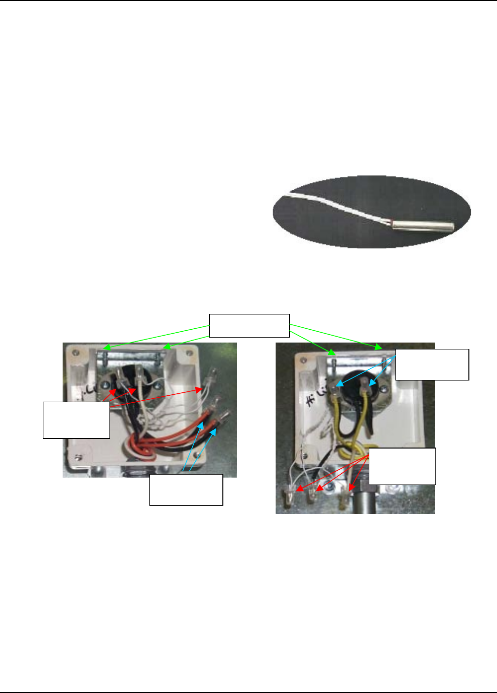
Portable Dryer Troubleshooting
103
Grain Sensor
Procedure for Locating, Testing and Replacing
a Defective Grain Temperature Sensor
Symptoms of a bad sensor may include:
· Temperature readings that are not consistent with the ambient outside temperature or with any
known verified grain temperatures entering the dryer.
· Grain temp open or grain temp short on Network dryers
· Display readings of 255° or –127°.
Grain Thermistor Sensor
Troubleshooting:
1. Locate the left and right grain sensor electrical boxes on the dryer (see drawing below)
2. Open each box by removing the lid. They are held in place by 4 phillips head bolts and nuts.
3. Once inside the box, determine which wires you need to test by identifying the wire routing.
Mounting Screws
Sensor Wires
(Small white
26 ga.)
Grain Thermal
Overheat wires
Sensor wires
(Small white
26 ga.)
Grain Thermal
Overheat wires
4. The grain sensor wires are small white (26 ga.) and are connected to a 18 ga. white and a 18 ga.
black wire with 2 of the smaller (26 ga.) grain sensor wires butt connected together.
5. The grain thermal overheat switch is a black disk mounted on a silver bracket with 2 black 18 ga.
wires connected to 2 colored wires.
6. Disconnect the white and black 18 ga. wires from the smaller white grain sensor wires.
7. Strip back about 1/4 inch from the end of each 26 ga. sensor wire.
8. With a ohm meter, set your scale to 20k (if its not a autorange model).
9. Place the black lead into the still butt connected wire connection with the 2 – 26 ga. wires.
10. Connect the red lead to either of the disconnected 26 ga. wires and make note of the reading.

Portable Dryer Troubleshooting
104
Procedure for Locating, Testing and Replacing
a Defective Grain Temperature Sensor. (continued)
11. Now move the red lead to the other disconnected 26 ga. wire and make note of this reading.
12. Go to the other side of the dryer and repeat steps 6 through 11.
13. You will notice that 3 readings will be very close to the same, but one reading will be different. This
is your defective sensor. (Compare readings to Resistance/Temperature chart page 62.)
14. If you don’t have a replacement sensor, jump to How to Bypass the Grain Temperature Sensor
Sensor Replacement:
15. The grain sensors are mounted to the grain overheat capillary and need to be removed together.
16. To remove the overheat switch disconnect the grain thermal overheat wires.
17. Then remove the 2 self tapping screws and slide the bracket, overheat switch and sensors out of
conduit.
18. Remove the tape surrounding the defective grain sensor then remove it.
19. Place your new sensor upon the capillary then apply tape to secure the sensor.
20. Slide the overheat switch and sensors back into the conduit until the bracket for the overheat switch
is in the same mounting position as before.
21. Replace both mounting screws back into the overheat switch mounting bracket.
22. Butt connect together one wire from each of the grain sensors.
23. Connect one of the remaining grain sensor wires to the Black 18 ga. wire.
24. Connect the other remaining grain sensor to the White 18 ga. wire.
25. Connect one of the grain overheat switch wire to each one of the colored wires.
26. Reconnect the other side of the dryer following steps 22 through 24.
27. Double check the wire connections then replace the covers on the boxes.
How to Bypass the Grain Temperature Sensor:
The following instructions are for situations where you don’t have an extra grain sensor to replace the
defective one. So now, we are going to rewire the sensors so that instead of using 4 sensors to monitor the
grain temperature with, we are only going to use one. The dryer will operate fine with only one sensor with
the exception of only being able to monitor one small section of the grain columns.
1. On the side of the dryer in which sensor is defective, leave this sensor and the joining sensor
disconnected from the white and black 18 ga. wires. Be sure to cap these 18 ga. wires off.
2. On the other side of the dryer, take one of the small white grain sensor wires and connect it to the
white 18 ga. wire.
Grain Sensor

Portable Dryer Troubleshooting
105
Procedure for Locating, Testing and Replacing
a Defective Grain Temperature Sensor. (continued)
3. From the same sensor that you connected to the white 18 ga. wire, connect the other small white
grain sensor wire to the black 18 ga. wire.
4. Double check the wire connections then replace the covers on the boxes.
Resistance / Temperature Chart
°F Ohms °F Ohms °F Ohms °F Ohms °F Ohms °F Ohms °F Ohms
28 36,601 62 14,546 96 6,382 130 3,047 164 1,565 198 855.7 232 494.3
29 35,565 63 14,179 97 6,238 131 2,985 165 1,536 199 841.4 233 86.8
30 34,562 64 13,822 98 6,097 132 2,925 166 1,508 200 827.3 234 479.4
31 33,591 65 13,475 99 5,960 133 2,865 167 1,480 201 813.6 235 472.1
32 32,650 66 13,139 100 5,826 134 2,807 168 1,453 202 800.1 236 464.9
33 31,739 67 12,811 101 5,696 135 2,751 169 1,427 203 786.8 237 457.9
34 30,856 68 12,493 102 5,569 136 2,696 170 1,401 204 773.8 238 451
35 30,000 69 12,184 103 5,446 137 2,642 171 1,375 205 761.1 239 444.2
36 29,171 70 11,884 104 5,325 138 2,589 172 1,350 206 748.6 240 437.6
37 28,368 71 11,591 105 5,208 139 2,537 173 1,326 207 736.3 241 431
38 27,590 72 11,307 106 5,093 140 2,487 174 1,302 208 724.3 242 424.6
39 26,835 73 11,031 107 4,981 141 2,438 175 1,279 209 712.5 243 418.3
40 26,104 74 10,762 108 4,872 142 2,390 176 1,256 210 700.9 244 412.1
41 25,394 75 10,501 109 4,766 143 2,343 177 1,234 211 689.6 245 406
42 24,707 76 10,247 110 4,663 144 2,297 178 1,212 212 678.4 246 400
43 24,040 77 10,000 111 4,562 145 2,252 179 1,190 213 667.5 247 394.1
44 23,394 78 9,760 112 4,463 146 2,208 180 1,169 214 656.8 248 388.3
45 22,767 79 9,526 113 4,367 147 2,165 181 1,149 215 646.2 249 382.7
46 22,159 80 9,298 114 4,273 148 2,123 182 1,129 216 635.9 250 377.1
47 21,569 81 9,077 115 4,182 149 2,082 183 1,109 217 625.8
48 20,997 82 8,862 116 4,093 150 2,042 184 1,089 218 615.8
49 20,442 83 8,652 117 4,006 151 2,003 185 1,070 219 606.1
50 19,903 84 8,448 118 3,921 152 1,965 186 1,052 220 596.5
51 19,380 85 8,249 119 3,838 153 1,927 187 1,034 221 587.1
52 18,873 86 8,056 120 3,757 154 1,890 188 1,016 222 577.9
53 18,380 87 7,868 121 3,678 155 1,855 189 998.3 223 568.8
54 17,902 88 7,685 122 3,601 156 1,820 190 981.2 224 559.9
55 17,438 89 7,506 123 3,526 157 1,785 191 964.4 225 551.2
56 16,988 90 7,333 124 3,453 158 1,752 192 947.9 226 542.6
57 16,551 91 7,164 125 3,381 159 1,719 193 931.8 227 534.2
58 16,126 92 6,999 126 3,311 160 1,687 194 915.9 228 525.9
59 15,714 93 6,839 127 3,243 161 1,655 195 900.4 229 517.8
60 15,313 94 6,682 128 3,176 162 1,624 196 885.2 230 509.8
61 14,924 95 6,530 129 3,111 163 1,594 197 870.3 231 502
Sensor Chart
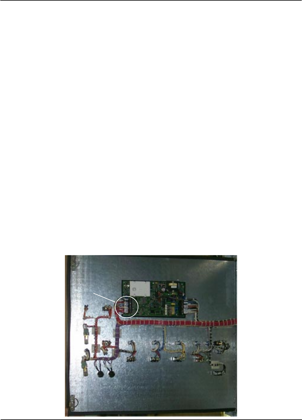
Portable Dryer Troubleshooting
106
Plenum Sensor
Procedure for Locating, Testing and Replacing
a Defective Plenum Temperature Sensor
Symptoms of a bad sensor may include:
Temperature readings that are not consistent with the ambient outside temperature or
with a verified plenum temperature that has been taken with a thermometer.
Erratic plenum display readings.
Plenum temp open or plenum temp short.
Troubleshooting:
1. The process of checking the sensor is similar to that of the grain sensors, but you
only have one sensor to check.
2. The actual plenum sensor is located in the plenum just inside the rear access door
to the right. (Facing the rear of the dryer)(See picture on next page)
3. Start at the CPU/Display board, it is located on the door of the lower box.(See below)
4. The wires from the sensor (which are butt connected at the sensor) go through a
conduit in the plenum section of the dryer.(See next page) That conduit terminates at
a white plastic 4"x4" junction box. This box is located on the front of the dryer to the left
of the fan/heater. (Facing the front of the dryer.) From that point to the CPU/Display board.
5. The wires are connected to terminals J7-12 (white wire) and J7-13 (black wire) on the
back of the Cpu/Display board.(see picture below)
6. Unhook those wires
7. What you will be checking is resistance in relationship to a known temperature.
(See resistance/temperature chart on previous page.)
8. With a ohm meter, set your scale to 20k (if it’s not a autorange model).
9. Place one probe of your meter on one wire going out to the sensor and the other
probe to the other wire.
10. The meter should read close to the resistance/temperature chart on previous page.
11. Assuming you have checked the wiring from the CPU/Display board to the sensor and
it is OK. But the resistance is not close to what is on the chart. You probably have a bad
plenum bolt sensor.
Plenum Sensor
Connected to
J7-12 & J7-13
Plenum Bolt
Sensor
(Part No. HF-7236)
Back of Door on Lower Box
CPU/Display Board
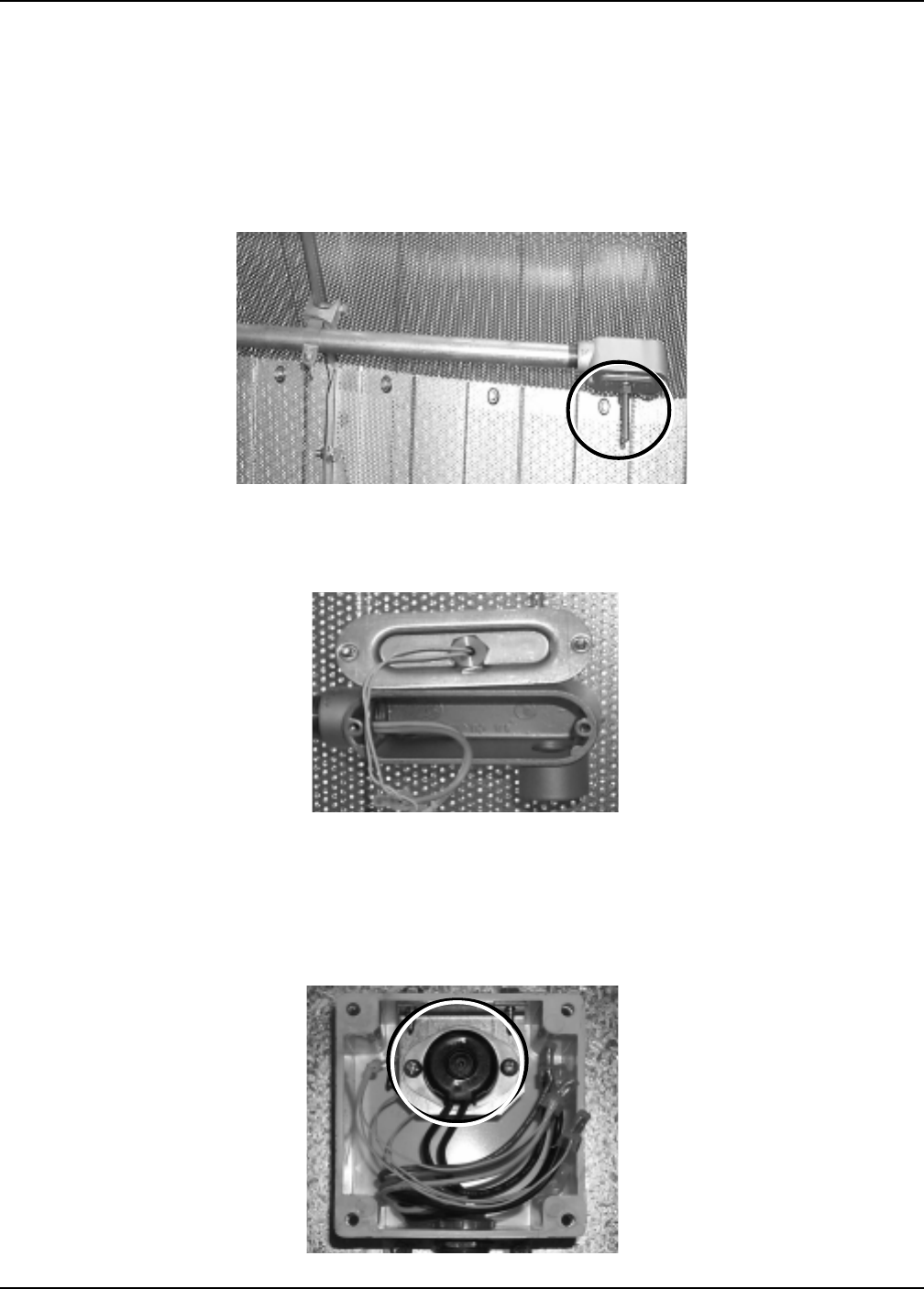
Portable Dryer Troubleshooting
107
Procedure for Locating, Testing and Replacing
a Defective Plenum Temperature Sensor
The picture below is of the plenum bolt sensor in the plenum of the dryer. See previous
page for more information.
Plenum Bolt Sensor (Part No. HF-7236)
View of back side of the plenum bolt sensor, as it is mounted in the conduit fitting.
(Located inside the dryer plenum, to the right, just inside the rear access door.)
View of the 4"x4" plastic junction box. This is located to the left of the fan/heater
facing the front of the dryer. It contains the plenum overheat and a juction point
where the wires from the plenum bolt sensor are butt connected together.
Plenum 300 Degree Overheat (10' Length)(Part No.D03-0004)
Plenum 300 Degree Overheat (24' Length)(Part No. D03-0377)
Plenum Sensor
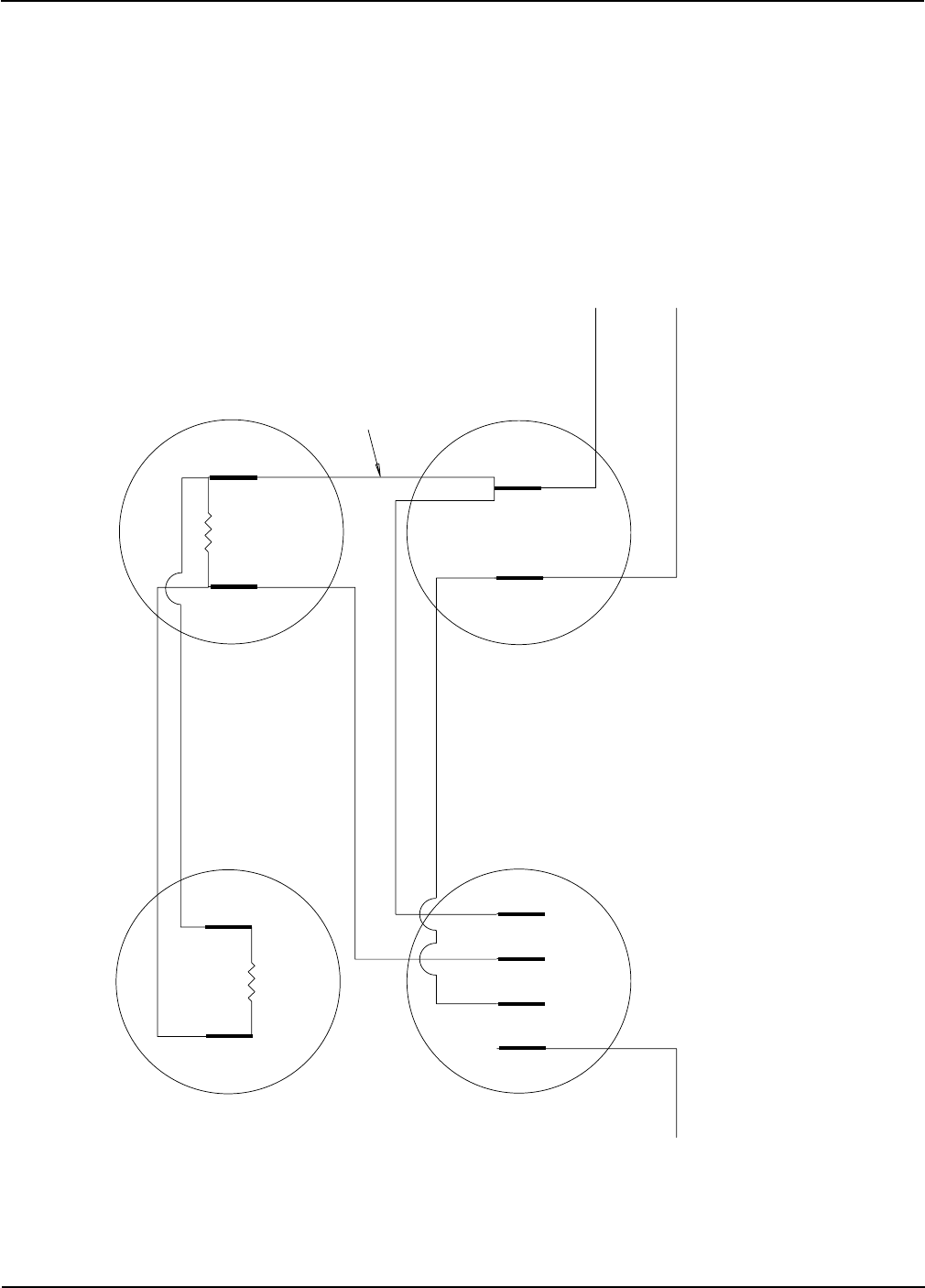
Portable Dryer Troubleshooting
108
Stern and Capacitor Diagram 10-17 HP 1Phase
WIRE #8 FROM MOTOR
WIRE #5 FROM MOTOR
WIRE #1 FROM MOTOR
216-259uF, 250VAC CAPACITOR
(ELECTROLYTIC)
PART# TFH-2104
216-259uF, 250VAC CAPACITOR
(ELECTROLYTIC)
PART# TFH-2104
60uF, 370VAC CAPACITOR
(OIL FILLED)
FH-6448
STEARNS SWITCH
PART# TF-1430 = 70 AMP
PART# TF-1709 = 90 AMP
1234
USE 12 GA. WIRE BETWEEN
ALL CAP AND SWITCH CONNECTORS
180 OHM 11 WATT 180 OHM 11 WATT
Competitor Wiring Reference

Portable Dryer Troubleshooting
109
OPERATION HINTS FOR COMPETITOR DRYERS
Present Software version is 2.19
1. BURNER CYCLING
Keep Low pressure setting as low as possible without shutting down dryer or popping. Approx. 1 to 2 lb.
Cycle on average 4 times per minute. 3 -5 times per minute is acceptable.
2. ERRORS
01 User switched from continuous flow to batch while dryer was running.
02 Grain Temperature Sensor Open. One or both leads are off (Open Circuit.).
03 Grain Temperature Sensor Leads are shorted together.
04 Plenum Temperature Sensor Open. One or both leads are off (Open Circuit).
05 Plenum Temperature Sensor Leads are shorted together.
06 Flame Probe Shorted to ground.
07 Illegal Flame Sense. Most likely caused by stuck open gas solenoid.
Error 7 will not shut down fan until loss of flame is detected by control. May occur if 1 of the 12 volt DC limits is
shorted to AC ground, or to the communication port for the air switch or either temperature sensor is shorted to
AC ground.
08 No safety circuit voltage.
09 I/O board communication failure. I/O board and Master board have lost communication.
10 User supplied safety. A safety connected to J7 -8 and J1-17.
11 Canadian Mercoid sensor. In USA jump J7-8 to J1-16.
BATCH ERRORS
BRN on the screen means the Burner Switch is turned off or there is a loose wire in its circuit.
FAN on the screen means the Fan Switch is turned off or there is a loose wire in its circuit.
Presently the Load Switch and the Unload Switch are not monitored by the Dryer Controls.
999 on the screen is not a n Error. It means the board has never had software loaded. This will come up when you
turn on the power just after GSI appears. This means the latest software must be down loaded.
3. DIP SWITCHES
1. Dip Switch 8 = Air Switch Test Bypass. WARNING! Bypassing this test will allow burner to come on
without the Fan running.
2. Dip Switch 7 = Emergency Cooling Mode. Fan will run alone for 5 minutes when the Start button is pushed with
switch on.
3. Dip Switch 6 = Allows Off/On Burner operation instead of High/Low as is standard.
4. Dip Switch 5 = (In Software Ver. 2.11 and up) Adds Low Temp Timer to a nd low Temp finish dry like dual temp.
Batch Dryer.
5. Dip Switch 4 = (In Software Ver. 2.14 and up) Adds Low Temp finish tripped by Grain Temperature to Batch
Mode.
4. SHUTDOWNS
If both the GRAIN and PLENUM HIGH TEMPERATURE warnings appear on the screen at the same time one of
the two mechanical temperature sensors are kicked out. NOTE Emergency Cooling will NOT work if these are
kicked out. These temperature limits are in addition to the electronics high limits and are located in the same
electrical conduits as the electronic thermister sensors. Note that J7-01 is the terminal the computer checks for
12 volts.
5. SPECIAL KEY USAGE
1. Pushing the UP arrow key will gives the Dryers Hour Meter reading. Two successive screens Hours x 100 |
Balance of hours.
In software vers. 2.14 and above it reads in 5 successive screens Total Hours x 100 | Balance of hours | Balance of
minutes | Batch Count | Minutes since last shutdown. So 5 | 23 | 12 | 144 | 188 would be Timer = 523 hours 12
minutes, 144 Batches dumped and 3 hours and 8 minutes since the last shutdown.
2. Pushing the DOWN arrow key while an error is on the screen will tell how long ago the shutdown occurred.
3. Pushing the MODE SELECT key exits any mode back to the main screen.
4. Holding the STOP button for 4 seconds or longer causes the Dry, Cool, and Unload timers to be reset to the
values programmed by the user. This also forces new times.
5. Holding down the HOURS key and turning on the power resets the NOVRAM or does what is called a HARD
BOOT.
6. Holding down the DOWN key while turning on the power restores the factory default settings.
7. In software vers. 2.19 and above Holding down the Up Arrow Key while powering up resets the Total Batch
Counter .
Operation Hints

Portable Dryer Troubleshooting
110
6. OPERATION HINTS
1. If you set a new timer setting which is lower then the present setting it becomes effective immediately. If it is
7. OPTIONAL WIRING POINTS
1. J7-10, J7-13 and J7-18 are 12 volt ground points for use with a tester.
There are no 12 volt ground connections on the IO board.
2. J1-17 - User Supplied Safety. If 12 volts is interrupted from J7-18 the User Supplied Safety Warning, ERROR 10
results.
3. J1-16 - Canadian Mercoid Sensor. If 12 volts in interrupted from J7-18 the Canadian Mercoid Warning, ERROR
11 results.
4. J1-15 - Discharge Hold Function – First available in Version 2.19 - operates in Batch Mode only.
If 12 volts is applied to J1-15 before the unload cycle is reached, when it does reach the unload cycle the dryer will
turn off the Fan and or the Heater (Only if the switches are in the AUTO position) and not allow the Dryer to unload
until the 12 volts is removed from J1-15. When 12 volts is not detected the dryer will resume normal operation and
immediately unload the Dryer and continue drying. This function cannot be activated if the unload cycle has
already begun. If you are running Dry and Cool and want the Dryer to continue cooling while in Discharge Hold put
the Fan switch in the Manual position. Otherwise both the Fan and Heater Switches should be in the AUTO
position.
5. J7-15, J7-16 and J7-17 are 12 volt Positive source points.
8. Temperature Sensor Testing
1. You can find charts with the Resistance readings at various Temperatures in the following manuals
The Competitors use the Thermister type sensors, the bolt style for the Plenum and the round style for the Grain
Temperature.
Located in Resource 2003 CD in the “Resources – Manuals” Folder
PNEG-630 Portable Dryer – Trouble Shooting
PNEG-377 Fan & Heater – Service Manual Feb 2000.pdf Page 50 (Fans and Heaters | Trouble Shooting Guide)
9. TROUBLESHOOTING TIPS
1. If some 110 volt contactor control devices work and some do not check the fuse on the IO board to see if it has
failed.
Likely devices that will not work are the Load Auger, Unload Auger and SCR drive.
OPERATION HINTS FOR COMPETITOR DRYERS
Operation Hints
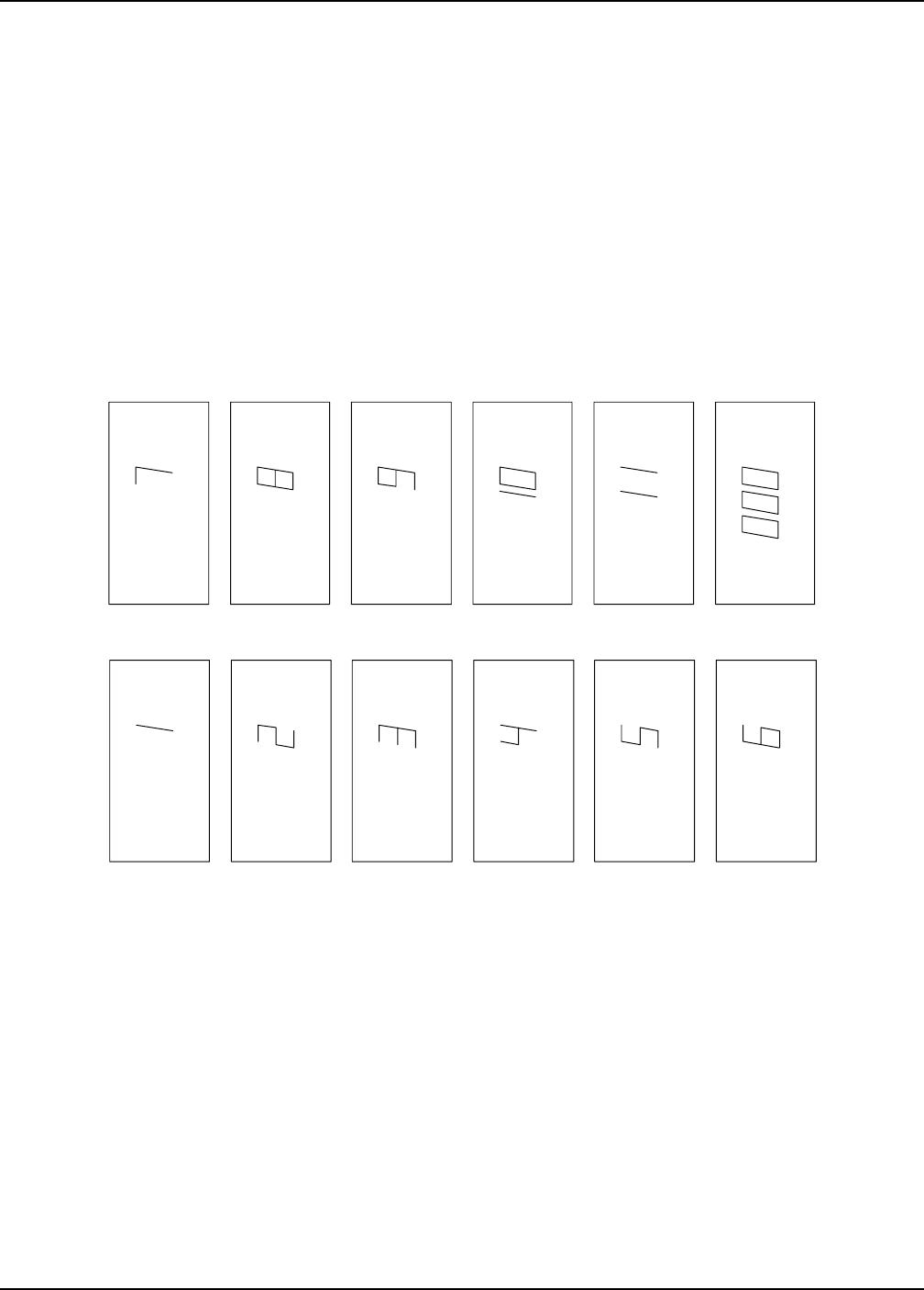
Portable Dryer Troubleshooting
111
Series 100 Error Conditions
This indicates that one of the other on
screen errors (vapor, plenum, housing
temp hi-limit, flame out, no airflow, motor
overload or rear discharge) has occured.
Mercoid gas pressure safety.
User supplied safety.
I/O board communication failure
I/O board and master have lost
communication.
No safety circuit voltage.
Illegal flame sense. Error 7 is most likely
caused by stuck open solenoid. Error 7 will
not shut down fan until loss of flame is
detected by control. Error 7 may also be
caused by a bad ballast resistor (ballast
resistor not open between poles). It may als
o
occur if 1 of the 12 volt DC limits is shorted t
o
AC ground, or either temperature senosr is
shorted to AC ground.
Flame probe shorted to AC ground.
Plenum temperature senosr leads are
shorted together OR sensor is shorted.
(See figure 4)
Plenum temperature sensor is open.
One or both leads are off (open circuit)
(See figure 4)
Grain temperature sensor leads are
shorted together OR sensor is shorted.
(See Figure 4)
Grain temperature sensor open. One
or both leads are off (open circuit)
(SEE FIGURE 4)
User switched from continuous flow to
batch while dryer is running.
ERROR
ERROR
ERROR
ERROR
ERROR
ERROR ERROR
ERROR
ERROR
ERROR
ERROR
ERROR
Error Codes
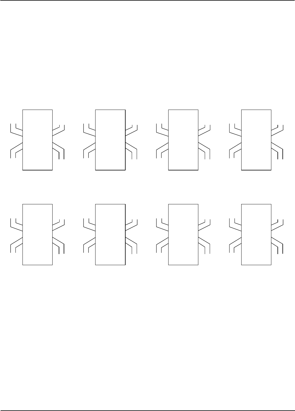
Portable Dryer Troubleshooting
112
Series 100 Error Conditions
PLENUM
ERROR
THIS DISPLAY INDICATES A LOSS OF AIR
PRESSURE INSIDE THE DRYER. THIS IS
USUALLY CAUSED BY LACK OF GRAIN INSIDE
THE DRYER. THE AIRSWITCH MAY ALSO NEED
TO BE ADJUSTED SO THAT IT BECOMES MORE
SENSITIVE TO AIR PRESSURE.
(SEE FIGURE 1)
THIS DISPLAY INDICATES THAT A MOTOR OVERLOAD
RELAY HAS TRIPPED. THIS RELAY MUST BE RESET
MANUALLY. OPEN THE UPPER CONTROL BOX DOOR
MAKE SURE THE POWER IS DISCONNECTED AND PUSH
IN THE RED LEVERS ON ALL OF THE OVERLOAD
RELAYS. NOTICE IF ONE OF THE LEVERS CLICKS
AS IT IS PUSHED IN. THEN INSPECT THE MOTOR
THAT TRIPPED THE RELAY. DETERMINE IF THE
MOTOR IS BEING OVERWORKED.
THIS DISPLAY INDICATES THAT THE GRAIN
DISCHARGE SWITCH LOCATED IN THE REAR
OF THE DRYER WAS ACTIVATED. THIS IS
CAUSED BY THE GRAIN EXITING THE DRYER
WAS NOT TAKEN AWAY FAST ENOUGH OR
SOMEONE HAS OPENED THE DISCHARGE LID.
(SEE FIGURE 13)
THIS DISPLAY INDICATES THE COMPUTER HAS
STOPPED SENSING FLAME. THIS CAN BE CAUSED
FROM RUNNING OUT OF FUEL, FLAME PROBE OUT
OF ADJUSTMENT, OR THE BURNER FAILED TO
IGNITE DURING IGNITION SEQUENCE.
THIS DISPLAY INDICATES THAT THE PLENU
ONE OF THE FIXED GRAIN HIGH LIMIT SWI
T
HAS TRIPPED. THESE SWITCHES RESET A
U
ICALLY WHEN COOLED DOWN. YOU MAY H
START THE DRYER IN EMERGENCY COOLI
N
(SEE FIGURE 5 AND FIGURE 14)
THIS DISPLAY INDICATES THAT THE HOUSI
HIGH LIMIT SWITCH HAS TRIPPED. TO RES
E
THIS SWITCH, REMOVE 2 SCREWS TO THE
OF THE LRL BOX ON TOP OF THE FAN/BUR
ASSEMBLY AND PUSH THE RED BUTTON I
N
THIS DISPLAY INDICATES THAT THE
VAPORIZER COIL NEEDS TO BE
ADJUSTED SO THAT IT RUNS COLDER.
(POSITION COIL AWAY FROM FLAME)
THIS DISPLAY INDICATES THAT THE OUT O
F
GRAIN TIMER HAS EXPIRED. TRY INCREASI
YOUR TIME ON THE OUT OF GRAIN TIMER.
UNLOAD TIME
OUT OF GRAIN TIME
COOL TIME
DRY TIME
PLENUM TEMPERATURE SET POINT
MOISTURE CONTROL SET POINT
LOAD DELAY
UNLOAD DELAY
ERROR OUT
GRAIN
000
UNLOAD TIME
OUT OF GRAIN TIME
COOL TIME
DRY TIME
PLENUM TEMPERATURE SET POINT
MOISTURE CONTROL SET POINT
LOAD DELAY
UNLOAD DELAY
TEMP HI-LIMIT
VAPOR
000
UNLOAD TIME
OUT OF GRAIN TIME
COOL TIME
DRY TIME
PLENUM TEMPERATURE SET POINT
MOISTURE CONTROL SET POINT
LOAD DELAY
UNLOAD DELAY
ERROR TEMP HI-LIMIT
HOUSING
000
UNLOAD TIME
OUT OF GRAIN TIME
COOL TIME
DRY TIME
PLENUM TEMPERATURE SET POINT
MOISTURE CONTROL SET POINT
LOAD DELAY
UNLOAD DELAY
ERROR TEMP HI-LIMIT
GRAIN
000
UNLOAD TIME
OUT OF GRAIN TIME
COOL TIME
DRY TIME
PLENUM TEMPERATURE SET POINT
MOISTURE CONTROL SET POINT
LOAD DELAY
UNLOAD DELAY
ERROR FLAME OUT
000
UNLOAD TIME
OUT OF GRAIN TIME
COOL TIME
DRY TIME
PLENUM TEMPERATURE SET POINT
MOISTURE CONTROL SET POINT
LOAD DELAY
UNLOAD DELAY
ERROR
000
DISCHARGE
UNLOAD TIME
OUT OF GRAIN TIME
COOL TIME
DRY TIME
PLENUM TEMPERATURE SET POINT
MOISTURE CONTROL SET POINT
LOAD DELAY
UNLOAD DELAY
ERROR
000
OVERLOAD
MOTOR
UNLOAD TIME
OUT OF GRAIN TIME
COOL TIME
DRY TIME
PLENUM TEMPERATURE SET POINT
MOISTURE CONTROL SET POINT
LOAD DELAY
UNLOAD DELAY
ERROR
NO AIRFLOW
000
Competitor Wiring Reference
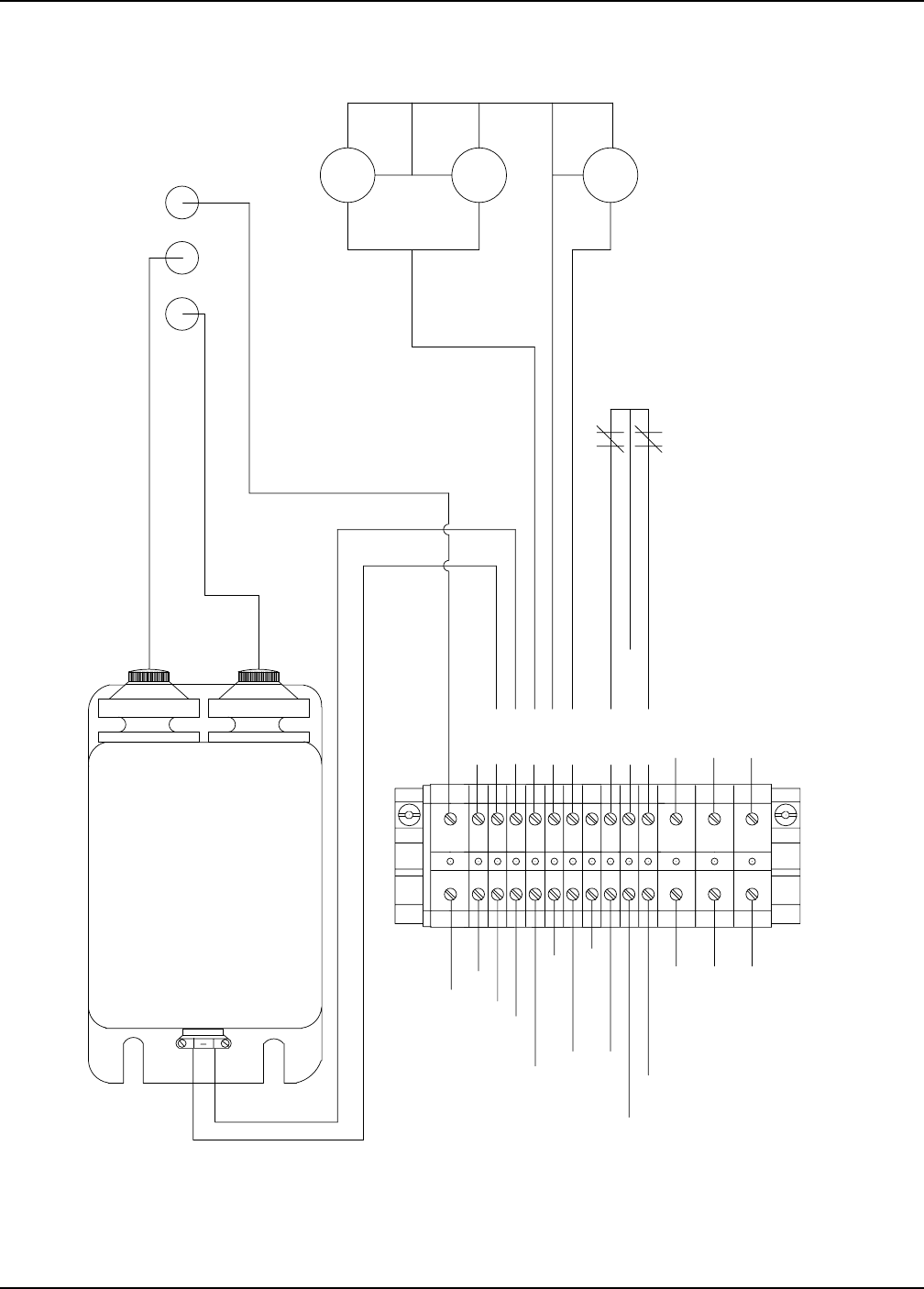
Portable Dryer Troubleshooting
113
Heater Circuit
J7-19 FLAME DETECTION ORANGE -
J6-07-IGNITION NEUTRAL---WHITE
J6-06-IGNITION POWER---BLACK
J7-13-VAPOR-PURPLE
J7-08-12V-RED
J7-02-HOUSING-YELLOW
J7-10-DC NEGATIVE - WHITE/BLACK STRIPE
J6-12-MAIN SOL.-BLACK
IGNITION TRANSFORMER
TYPE 312-24A402V CODE D97T
PRI V SEC V HZ PRI A SEC A
120 10,000 60 2.2 .023
SECONDARY MIDPOINT GROUNDED
Webster
PART# HH-1093
J6-14-CYCLE SOL-BROWN
SILICONE HIGH VOLTAGE IGNITION WIRES
J7-20---WHITE TO FLAME PROBE BASE FLAME PROBE NEUTRAL---WHITE
J6-13-MAIN&CYCLE SOL. NEUTRAL-WHITE BLACK
WHITE
YELLOW
YELLOW/PURPLE
PURPLE
GRN
LOW
LIQUID
HIGH
HOUSING
VAPOR
FLAME PROBE (SILICONE WIRE)
BLACK
BLACK
BROWN
GRN
Competitor Wiring Reference
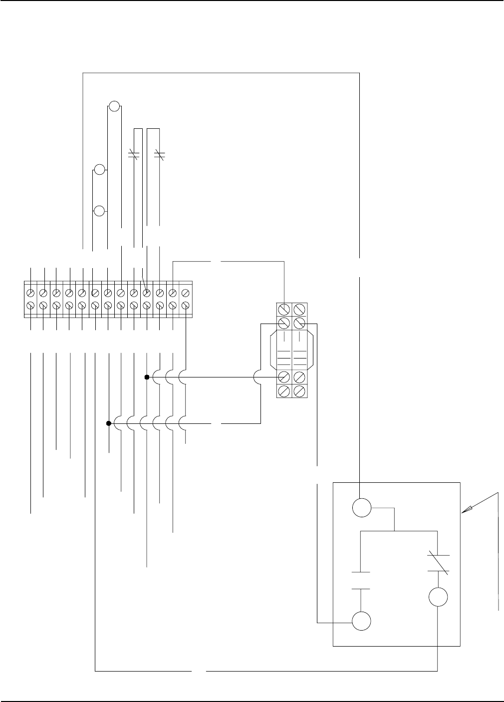
Portable Dryer Troubleshooting
114
J7-10 12VDC NEGATIVE WHITE/BLACK STRIP
1
PINK
WHITE
BROWN
GREY
J7-02 HOUSING HIGH LIMIT
J6-14 CYCLE SOLENOID POWER
J6-13 MAIN/CYCLE SOLENOID NETURAL
WHT
J7-19 FLAME DETECTION
ORG
J7-20 FLAME PROBE NEUTRAL
WHT
J6-07 IGNITION TRANSFORMER NEUTRAL
J6-06 IGNITION TRANSFORMER POWER
BLK
FLAME PROBE (SILICONE WIRE)
FLAME PROBE NEUTRAL ---- WHITE
BLACK
BLACK
13
12
11
INSIDE VIEW OF MERCOID
TERMINAL HOOKUPS
BRN
BLACK
BROWN
GREY MERCOID
SWITCH
WIRING
MERCOID
PRESSURE SWITCH
WHT
SOLENOIDS
BROWN
BLK
MERCOID SAFETY
RELAY
BROWN
PNKJ1-16 MERCOID SAFETY
10
9
2
3
4
5
6
7
8
BLK
PUR
RED
YEL
YELLOW
YELLOW
PURPLE
PURPLE
WHITE
BLACK
BLK
J6-12 MAIN SOLENOID POWER
HIGH
LOW
LIQUID
HOUSING
VAPOR
J7-08 12 VDC
J7-13 VAPOR HIGH LIMIT
Fan Burner Circuit For Canadian Models Only
Competitor Wiring Reference
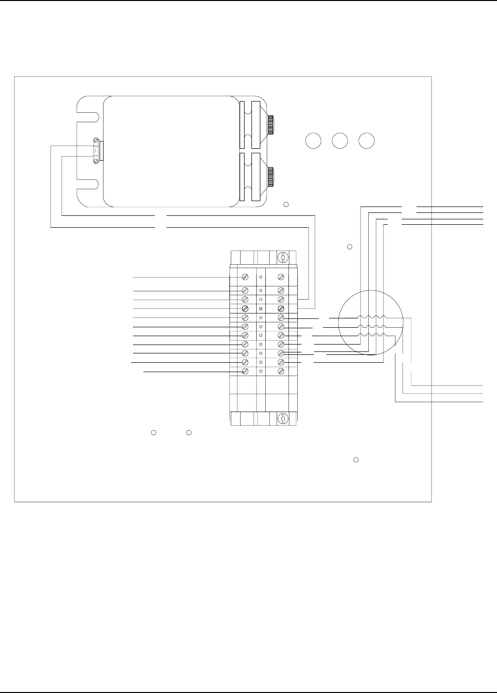
Portable Dryer Troubleshooting
115
S228LP.PRT
J7-10 WHT/BLK
J7-02 YEL
J7-08 RED
J7-13 PUR
J6-14 BRN
J6-13 WHT
J6-12 BLK
J6-06 BLK
J6-07 WHT
J7-20 WHT
J7-19 ORG
BROWN
WHITE
BLACK
YELLOW
YELLOW PURPLE
PURPLE
WIRES:
1 - WHITE
1 - BLACK
1 - BROWN
1 FOOT LONG
FROM OUTSIDE
OF BOX
WIRES:
2 - PURPLE
2 - YELLOW
3 FEET LONG
FROM OUTSIDE
OF BOX
BLACK
WHITE
BLACK
BLACK
PURPLE
YELLOW
YELLOW
PURPLE
BROWN
PART# HH-1093
Webster
IGNITION TRANSFORMER
TYPE 612-6A7 CODE J94E
PRI V SEC V HZ PRI A SEC A
120 10,000 60 2.2 .023
SECONDARY ENDPOINT GROUNDED
Series 100 LP 26"/28" Fan
Competitor Wiring Reference
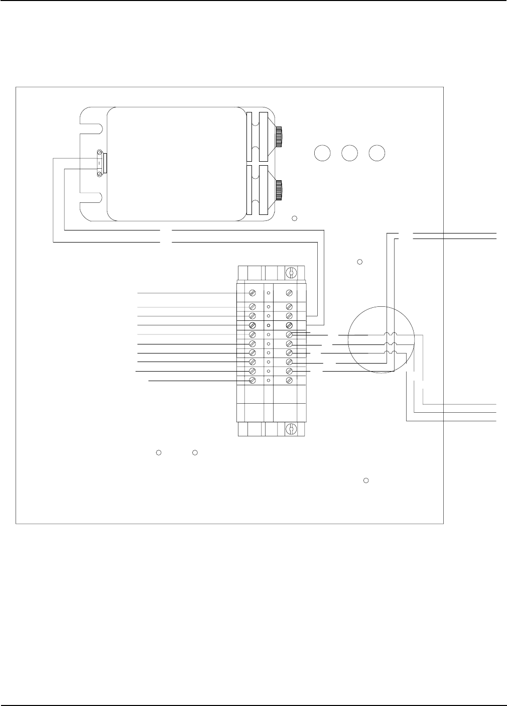
Portable Dryer Troubleshooting
116
Series 100 Natural Gas 26"/28" Fan
S228NG.PRT
J7-10 WHT/BLK
J7-02 YEL
J7-08 RED
J6-14 BRN
J6-13 WHT
J6-12 BLK
J6-06 BLK
J6-07 WHT
J7-20 WHT
J7-19 ORG
BROWN
WHITE
BLACK
YELLOW
YELLOW
WIRES:
1 - WHITE
1 - BLACK
1 - BROWN
1 FOOT LONG
FROM OUTSIDE
OF BOX
WIRES:
2 - YELLOW
3 FEET LONG
FROM OUTSIDE
OF BOX
BLACK
WHITE
BLACK
BLACK
YELLOW
YELLOW
BROWN
BLACK
PART# HH-1093
Webster
IGNITION TRANSFORMER
TYPE 612-6A7 CODE J94E
PRI V SEC V HZ PRI A SEC A
120 10,000 60 2.2 .023
SECONDARY ENDPOINT GROUNDED
Competitor Wiring Reference
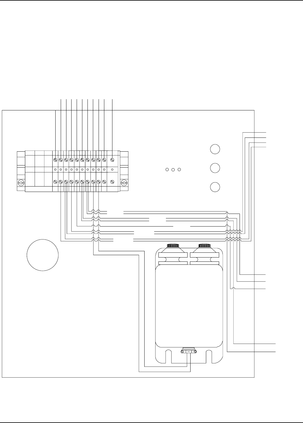
Portable Dryer Troubleshooting
117
Series 100 LP 36"/42" Fan
YEL
PUR
BLK
WHT
YEL
PUR
WHT
BRN
BLK
BLK
BLK
J7-10 WHT/BLK
J7-02 YEL
J7-08 RED
J7-13 PUR
J6-14 BRN
J6-13 WHT
J6-12 BLK
J6-06 BLK
J6-07 WHT
J7-20 WHT
J7-19 ORG
BROWN
BLACK
WHITE
YELLOW
PURPLE
12 FEET LONG
FROM OUTSIDE
OF BOX
1 FEET LONG
FROM OUTSIDE
OF BOX
3 FEET LONG
FROM OUTSIDE
OF BOX
WIRES:
1 - WHITE
1 - BLACK
WIRES:
1 - BROWN
1 - WHITE
1 - BLACK
WIRES:
2 - PURPLE
2 - YELLOW
S242LP.PRT
PART# HH-1093
Webster
IGNITION TRANSFORMER
TYPE 312-24A402V CODE D97T
PRI V SEC V HZ PRI A SEC A
120 10,000 60 2.2 .023
SECONDARY MIDPOINT GROUNDED
Competitor Wiring Reference
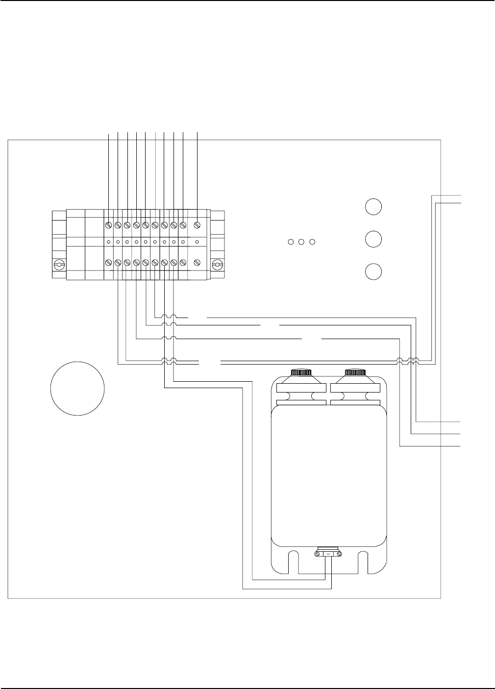
Portable Dryer Troubleshooting
118
Series 100 Natural Gas 36"/42" Fan
YEL
BLK
WHT
YEL
WHT
BRN
BLK
BLK
BLK
J7-10 BLK/WHT
J7-02 YEL
J7-08 RED
J6-14 BRN
J6-13 WHT
J6-06 BLK
J6-12 BLK
J6-07 WHT
J7-20 WHT
J7-19 ORG
BROWN
BLACK
WHITE
YELLOW
1 FEET LONG
FROM OUTSIDE
OF BOX
3 FEET LONG
FROM OUTSIDE
OF BOX
WIRES:
1 - BROWN
1 - WHITE
1 - BLACK
WIRES:
2 - YELLOW
S242NG.PRT
PART# HH-1093
Webster
IGNITION TRANSFORMER
TYPE 612-6A7 CODE J94E
PRI V SEC V HZ PRI A SEC A
120 10,000 60 2.2 .023
MIDPOINT GROUNDED
Competitor Wiring Reference

Portable Dryer Troubleshooting
119
Warranty
EXCEPT FOR THE ABOVE STATED EXPRESS LIMITED WARRANTIES, GSI MAKES NO WAR-
RANTY OF ANY KIND, EXPRESSED OR IMPLIED, INCLUDING, WITHOUT LIMITATION, WAR-
RANTIES OF MERCHANTABILITY OR FITNESS FOR A PARTICULAR PURPOSE OR USE IN CON-
NECTION WITH (i) PRODUCT MANUFACTURED OR SOLD BY GSI OR (ii) ANY ADVICE, INSTRUC-
TION, RECOMMENDATION OR SUGGESTION PROVIDED BY AN AGENT, REPRESENTATIVE OR
EMPLOYEE OF GSI REGARDING OR RELATED TO THE CONFIGURATION, INSTALLATION, LAY-
OUT, SUITABILITY FOR A PARTICULAR PURPOSE, OR DESIGN OF SUCH PRODUCT OR PROD-
UCTS.
IN NO EVENT SHALL GSI BE LIABLE FOR ANY DIRECT, INDIRECT, INCIDENTAL OR CON-
SEQUENTIAL DAMAGES, INCLUDING, WITHOUT LIMITATION, LOSS OF ANTICIPATED PROF-
ITS OR BENEFITS. PURCHASER'S SOLE AND EXCLUSIVE REMEDY SHALL BE LIMITED TO THAT
STATED ABOVE, WHICH SHALL NOT EXCEED THE AMOUNT PAID FOR THE PRODUCT PUR-
CHASED. THIS WARRANTY IS NOT TRANSFERABLE AND APPLIES ONLY TO THE ORIGINAL
PURCHASER. GSI SHALL HAVE NO OBLIGATION OR RESPONSIBILITY FOR ANY REPRESEN-
TATIVE OR WARRANTIES MADE BY OR ON BEHALF OF ANY DEALER, AGENT OR DISTRIBU-
TOR OF GSI.
GSI ASSUMES NO RESPONSIBILITY FOR FIELD MODIFICATIONS OR ERECTION DEFECTS
WHICH CREATE STRUCTURAL OR STORAGE QUALITY PROBLEMS. MODIFICATIONS TO THE
PRODUCT NOT SPECIFICALLY COVERED BY THE CONTENTS OF THIS MANUAL WILL NUL-
LIFY ANY PRODUCT WARRANTY THAT MIGHT HAVE BEEN OTHERWISE AVAILABLE.
THE FOREGOING WARRANTY SHALL NOT COVER PRODUCTS OR PARTS WHICH HAVE
BEEN DAMAGED BY NEGLIGENT USE, MISUSE, ALTERATION OR ACCIDENT. THIS WARRANTY
COVERS ONLY PRODUCTS MANUFACTURED BY GSI. THIS WARRANTY IS EXCLUSIVE AND IN
LIEU OF ALL OTHER WARRANTIES EXPRESS OR IMPLIED. GSI RESERVES THE RIGHT TO MAKE
DESIGN OR SPECIFICATION CHANGES AT ANY TIME.
PRIOR TO INSTALLATION, PURCHASER HAS THE RESPONSIBILITY TO RESEARCH AND
COMPLY WITH ALL FEDERAL, STATE AND LOCAL CODES WHICH MAY APPLY TO THE LOCA-
TION AND INSTALLATION.
THE GSI GROUP, INC. ("GSI") WARRANTS ALL PRODUCTS MANUFACTURED BY GSI TO BE
FREE OF DEFECTS IN MATERIAL AND WORKMANSHIP UNDER NORMAL USAGE AND CONDI-
TIONS FOR A PERIOD OF TWENTY-FOUR MONTHS AFTER RETAIL SALE TO THE ORIGINAL END
USER OF SUCH PRODUCTS. GSI'S ONLY OBLIGATION IS, AND PURCHASER'S SOLE REMEDY
SHALL BE FOR GSI, TO REPAIR OR REPLACE, AT GSI'S OPTION AND EXPENSE, PRODUCTS
THAT, IN GSI'S SOLE JUDGMENT, CONTAIN A MATERIAL DEFECT DUE TO MATERIALS OR
WORKMANSHIP. ALL DELIVERY AND SHIPMENT CHARGES TO AND FROM GSI'S FACTORY
WILL BE PURCHASER'S RESPONSIBILITY. EXPENSES INCURRED BY OR ON BEHALF OF THE
PURCHASER WITHOUT PRIOR WRITTEN AUTHORIZATION FROM AN AUTHORIZED EMPLOYEE
OF GSI SHALL BE THE SOLE RESPONSIBILITY OF THE PURCHASER.

1004 E. Illinois St.
Assumption, IL 62510-0020
Phone 217-226-4421
2004 Edition
