GuangZhou Walkera Technology TX624 HELIMAX User Manual HMXE0804 Novus CP indd
GuangZhou Walkera Technology Co., Ltd HELIMAX HMXE0804 Novus CP indd
UserManual.wiki
>
GuangZhou Walkera Technology
>
TX624 User Manual
Users Manual
Navigation menu
Upload a User Manual
Namespaces
Wiki Guide
HTML
PDF
Info
Views
User Manual
Discussion / Help
Navigation
![Length: 10.7 in [272mm] Width: 2 in [50mm] Height: 3.74 in [95mm] Rotor Span: 12 in [305mm] Flying Weight: 2.41 oz [68.4g] (with supplied fl ight battery)Novus CP Specifi cationsEntire Contents © Copyright 2009 HMXE0804 Mnl 01™](https://usermanual.wiki/GuangZhou-Walkera-Technology/TX624/User-Guide-1074959-Page-1.png)
![2IMPORTANT PRECAUTIONSIMPORTANT PRECAUTIONS● Only use the included charger with the included battery or replacement battery (GPMP0408).● Do not attempt to use this charger with NiCd or NiMH battery packs.● Never charge in excess of 4.20V per cell. ● If the battery should become damaged, discard the battery. Do not attempt to use a damaged battery.● Do not leave the charger unattended while charging. Disconnect the battery and remove input power from the charger immediately if either becomes hot! However, it is normal for the charger to get warm.● Disconnect the battery from the charger and carefully move the battery to a fi reproof location if the battery begins to swell or smoke!● Never charge at currents greater than 1C.● Always charge in a fi reproof location.● Never trickle charge.● Never allow the battery temperature to exceed 140° F [60° C].● Never disassemble or modify pack wiring in any way or puncture cells.● Never discharge below 2.75V per cell.● Do not allow water, moisture or foreign objects into the charger.● Do not block the air intake holes, which could cause the charger to overheat.● Do not place the charger or any battery on a fl ammable surface or near a combustible material while in use.● Do not charge on a carpet, cluttered workbench, paper, plastic, vinyl, leather, wood, or inside an R/C model.● Never charge inside a full-sized vehicle.● Always disconnect the battery from the charger and the power supply from the charger when not in use.● Do not attempt to charge a battery if it is swollen or hot.● ALWAYS KEEP OUT OF REACH OF CHILDREN.](https://usermanual.wiki/GuangZhou-Walkera-Technology/TX624/User-Guide-1074959-Page-2.png)

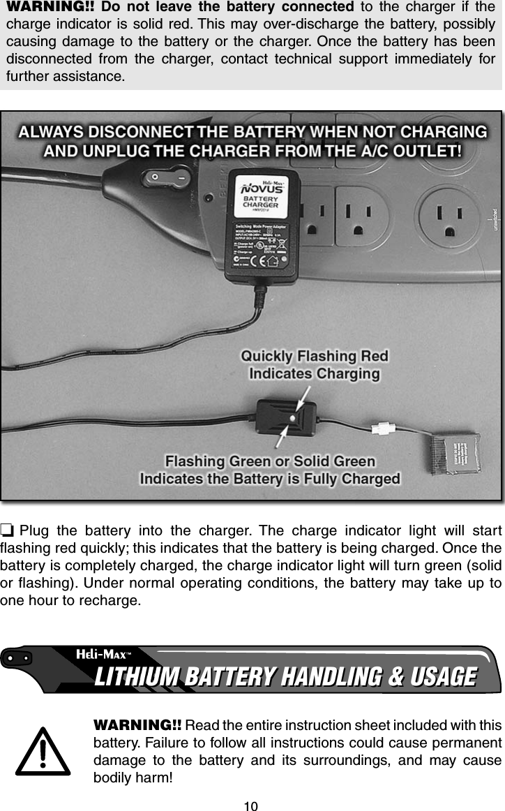
![11Land your model immediately when the battery begins to lose power. Recharge the battery before attempting another fl ight. A dangerous situation can occur when attempting to recharge an over-discharged battery!● ALWAYS charge the battery inside a fi reproof container placed in a fi reproof location clear of combustible materials. Failure to do so can result in property damage and/or bodily harm!● ALWAYS keep charging batteries within eyesight. Leaving the battery unattended is dangerous!● ALWAYS keep a supply of sand accessible when charging. Dumping sand on the battery will extinguish the LiPo chemical fi re.● NEVER use anything EXCEPT a LiPo approved charger.● NEVER charge over 4.20V per cell.● NEVER charge at currents greater than 1C.● NEVER charge through the “To ESC” or “DISCHARGE” lead.● NEVER trickle charge, or allow the battery to discharge below 2.75V per cell.● NEVER allow the battery temperature to exceed 140° F [60° C].● NEVER disassemble or modify the pack wiring in any way or puncture cells.● ALWAYS KEEP OUT OF REACH OF CHILDREN.Electric Motor WarningElectric motors are very dangerous. Do not work on the model while the fl ight battery is plugged in as interference may cause the main rotor blades to spin, possibly causing injury to yourself.WARNING!! Once the fl ight battery is connected the helicopter will have full power available. You must take proper measures to ensure that the throttle stick is not moved and that the idle up switch is not turned on while handling the model.](https://usermanual.wiki/GuangZhou-Walkera-Technology/TX624/User-Guide-1074959-Page-11.png)
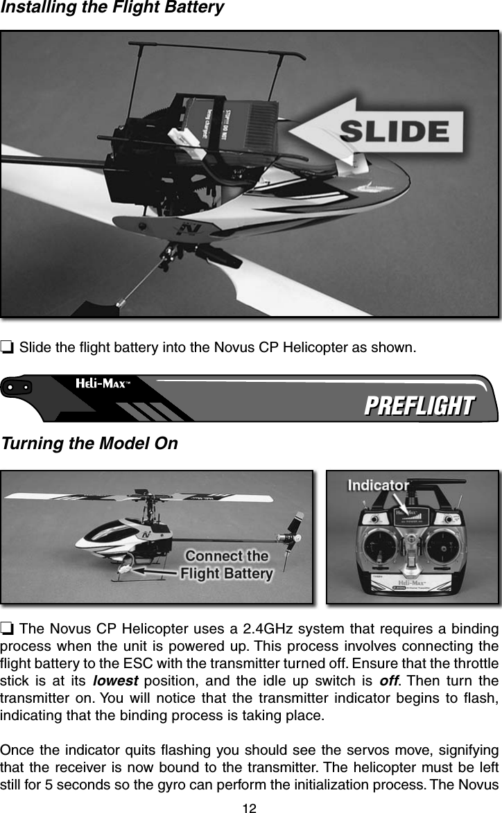
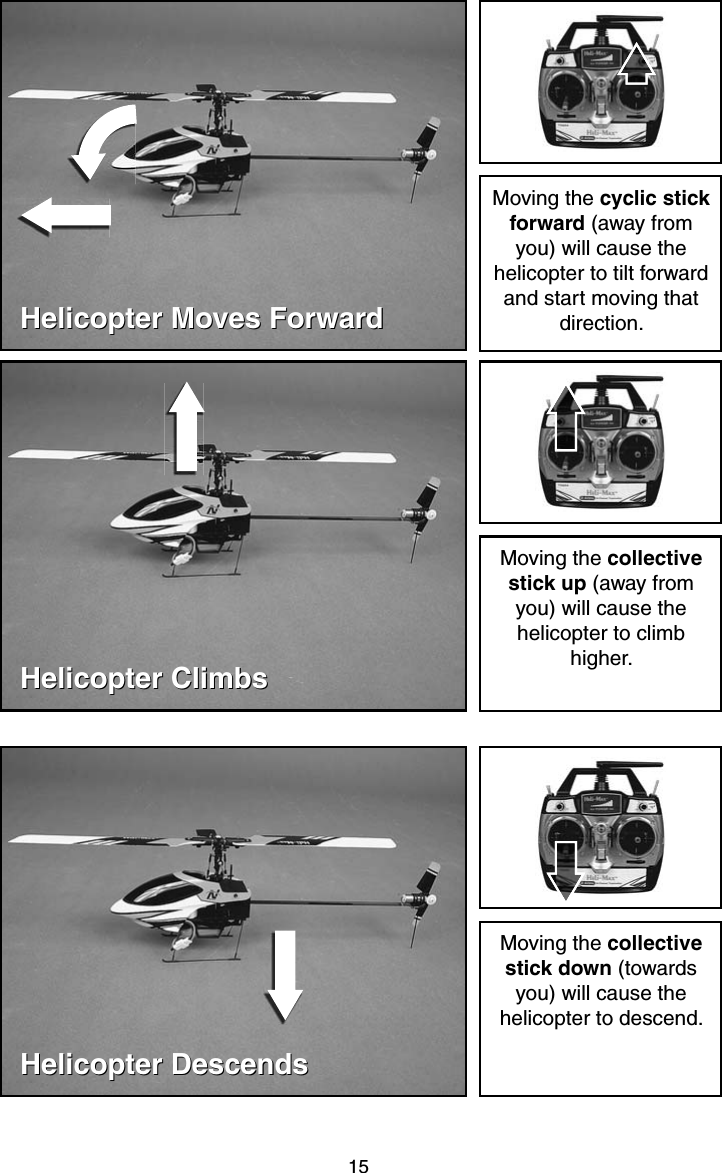
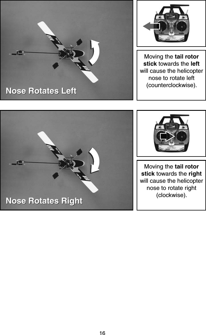
![13CP Helicopter is now ready for fl ight. Always step 15 feet [4.5m] away from the Novus CP Helicopter before operating the throttle. Do not hold the model while operating the throttle.A safe start is built into the Novus CP Helicopter that prevents the motor from activating unless the collective stick has been lowered to the lowest position. If the motor won’t run and turn the main blades, please make sure the collective stick is all the way down with the trim in its lowest position and leave it there for a couple of seconds. Then try moving the stick up slowly.Balance the Main BladesThe Novus CP Helicopter main rotor blades are already balanced and ready to fl y.CONTROLSCONTROLSTransmitter ControlsAll controls described as follows are with the tail pointing directly towards you. This is the best way to start out since it keeps the control inputs oriented the same. Once you start getting comfortable you can work on side hovering and nose-in.](https://usermanual.wiki/GuangZhou-Walkera-Technology/TX624/User-Guide-1074959-Page-13.png)
![17FLYINGFLYINGThe Heli-Max Novus CP is an extremely lightweight helicopter. Taking that into consideration, you should only fl y the helicopter indoors or in calm winds less than 1mph. Until you become accustomed to the Novus CP helicopter we highly recommend fl ying it in a large area of at least 35 feet [10.5m] square with no obstacles. The Novus CP will not fl y well in ground effect (air disturbance when the model is hovered below 1 foot [30cm]). Please maintain a minimum altitude of 1foot [30cm] to avoid ground effect. CrashingWe already know that crashing is going to occur. Once you realize the model is going to collide with something or crash into the ground, you should always turn the idle up switch off and bring the throttle stick all the way down to stop the main rotor blades from rotating. If you can remember to do this, chances are you will not damage the helicopter in the crash. The main rotor blades carry a lot of RPM and inertia during fl ight. Cutting the power to the main rotor blades will prevent most of the crash damage.TakeoffSlowly add power and observe the model. If you feel it needs trimming, do so before lift off. You will fi nd that model helicopters never allow you to return the sticks to center. You just need to position the stick as needed to maintain a steady hover.You will notice the cyclic controls lag behind your inputs. This is perfectly normal and something you get the feel for with time. It’s normal to drift around a little in a hover until you get used to fl ying the model. The cyclic controls are fairly sensitive so only small movements are necessary.HoveringOnce the helicopter is up in the air, simply try to hold it in one spot. This can take some practice. Wind or air currents have a big effect on the stability of the helicopter as well. Be patient and slowly work forward, as trying to rush the learning process can be costly.LandingLevel the helicopter into a steady hover and slowly decrease power until the helicopter settles onto the ground.](https://usermanual.wiki/GuangZhou-Walkera-Technology/TX624/User-Guide-1074959-Page-17.png)
![18Basic ManeuversOnce you become comfortable with hovering at different orientations and landing, it’s time to move on to more advanced maneuvers.Slow Pirouettes – Add a small amount of tail rotor (left or right) and try rotating the helicopter slightly sideways and see if you can hold it there. If you feel uncomfortable, then bring the tail back toward you. Once you start getting comfortable, try moving the helicopter to the side. Then turn back and fl y back to the other side in straight lines. Once you get that down you can try rotating the helicopter around 360 degrees, which is called a pirouette. The helicopter can drift during these so make sure you have plenty of room when you fi rst start practicing.Nose-in Hovering – After pirouettes it’s time to move on to nose-in hovering. Take off and climb to 10 feet [3m]. Practice half pirouettes from tail in to nose-in hovering and try to lengthen the delay in between. This will give you a little practice nose-in and still give you a chance to get out of trouble. As you improve you’ll remain nose-in for longer periods of time.GOOD LUCK AND GREAT FLYING!](https://usermanual.wiki/GuangZhou-Walkera-Technology/TX624/User-Guide-1074959-Page-18.png)