Guangzhou Chiyuan Electronic HT8 Quadcopter RF Module User Manual Manual 1 2
Guangzhou Chiyuan Electronic Co.,Ltd Quadcopter RF Module Manual 1 2
Contents
- 1. Manual 1-2
- 2. Manual 2-2
Manual 1-2
GUANGZHOU CHIYUAN ELECTRONIC CO.,LTD
Add: 4/F.,No.1 Boyi lndustrial Garden,4th Gongye Rd.Zhicun,
Dashi Street,Panyu Dis,Guangzhou,China P.C: 511430
Tel: +86-20-62326088 Fax: +86-20-62326077
E-mail: xinyi@chiyuan.net
Quadcopter
RF MODULE
www.chiyuan.net

Manual
Ff120
CONTENTS
Foreword 2
Important statement 2
1.Definition of FF120 flying orientation
2.Standard equipment
3.Setup of the Receiver
4.RF MODULE INSTRUCTION
5.Advice parameters to RF Module
6. Instruction for XC-IS2 Charger
7.Steps of flight
8.Flight Control diagram
9.Steps of Ending flight
10.Addition Instruction
11.Exploding View
12. Parts list
13. Accessories list
Specifications and Features
4
4
5
6
7
8
8
9
11
11
12
13
14
15
Please use HiSKY original spare prats to
upgrade, modify or maintain your FF120 in
order to ensure its safety. Please operate your
FF120 within the range or functions permitted.
It is forbidden to use it outside of the safety
laws or regulations.
注意事项
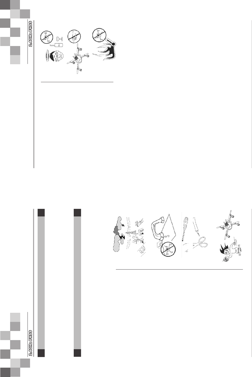
A.Far away from obstacles and people
Important Statement
B. Keep away from humidity
C. Proper operation and maintenance.
D. Avoid flying alone
E. Safe operation
F. Away from highly spinning parts
G. Protect from heat
2.Attention before flight
1.Important statement
Foreword
2 3
Manual
Ff120
Manual
Ff120
An FF120 in flight has risk of uncertain flight
speed and direction which is potentially
dangerous.When flying, please keep your
FF120 far away from people, high buildings,
high-tension lines, etc, and avoid operating in
rain, storms, thunder and lightening.
FF120 should be kept away from humidity
and vapor because its complex, and precise
electronic components and mechanical parts
may be damaged.
At the beginning of learning about radio-
controlled flight there are some difficulties to
overcome. Please avoid flying alone. Invite
experienced pilots to guide you (two of the
most effective methods to practice are via a PC
flight simulator and/or under the supervision of
a skilled pilot).
Please fly your FF120 according to your
physical status and flight skills. Fatigue,
listlessness and mis-operation will increase the
possibilities or accidental hazard.
Please keep pilot, people and object away from
the spinning blades of high main rotor and tail
rotor.
An Quadcopter FF120 is made from metal,
fiber, plastic and electronic components, etc.
Please keep away from heat and sunshine in
order to avoid distortion, even damage, caused
by high temperatures.
A. Ensure the battery packs of both transmitter and receiver and fully
charged(saturated).
B. Ensure both the throttle stick and the throttle trim of your transmitter stay at
the lowest positions before operation.
C. Please strictly obey the order of turn on and turn off before operation. When
starting your flight, please turn on your transmitter first, and connect the
power cable of your FF120 last. When finishing your flight, please disconnect
the power cable of your FF120 first and turn off your transmitter last.
D. An upset in the order of connection may cause your FF120 to loose control. Please
cultivate a correct habit of turn on and turn off.
Dear Customers:
Thanks for purchasing a HiSKY radio control aircraft product. In order to quickly and
safely master the operation of the FF120, pease read the manualcarefully and then keep
it in a safe place for future consultation and reference.
FF120 is a high risk hobby, whose flight should be kept far away from other people.
Mis-assembled or broken main frame,defective electronic equipment, and/or problematic
radio system will lead to unforeseen accidents such as bodily injury or property damage.
The pilot MUST pay attention to the flight safety and UNDERSTAND his responsibility for
accidents caused by his careless.
1. Definition of FF120 Orientation
UP
down
front back
right
left
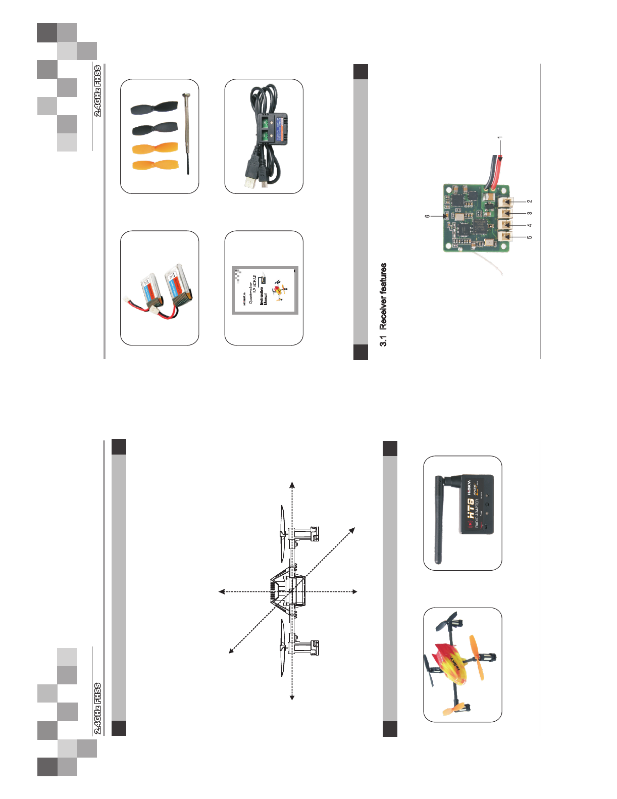
2. Standard equipment
Quadcopter FF120 RF MODULE HT8
Li-polymer battery pack Main rotor blades.
cross screwdriver
XC-IS2 Charger
Manual
3. Setup of the Receiver
3.1 Receiver features
(1) It adopts 2.4G spread spectrum technology.
(2) Integrated design of 3-Axis gyro and 3- Axis accelerator
4 5
Manual
Ff120
Manual
Ff120
We define the orientation fo FF120 in order not to cause confusion in the
following descriptions. That is to say, the tail boom of FF120 is facing the pilot
(tail in), and its head facing forward(front of pilot). The left hand of pilot is the
left side of FF120, the right hand of pilot is the right side of FF120. Its head is
to the front and its tail boom is to the back. The direction in which main body
of FF120 is facing up, and its skids are facing down.
2345
6
1
3.2 Function of receiver
Note:
4. RF MODULE INSTRUCTION
6 7
Manual
Ff120
Manual
Ff120
S/N Name of short Full name Function
1 Power wire Connect to the lipo battery
2 Right front motor
3 Right back motor
4 Left back motor
5 Left front motor
6 Signal indicator light Show the bind status(green)
The bind plug face
towards right
Connect to the right front
motor wire
Connect to the right back
motor wire The bind plug face
towards right
Connect to the left back
motor wire The bind plug face
towards right
Connect to the left front
motor wire The bind plug face
towards right
Green light: When in the code paring status, the receiver indicator will flash green,;After
code paring successfully the green light turns solid; If the green light turns off means
failure bind or has not receive the signal.
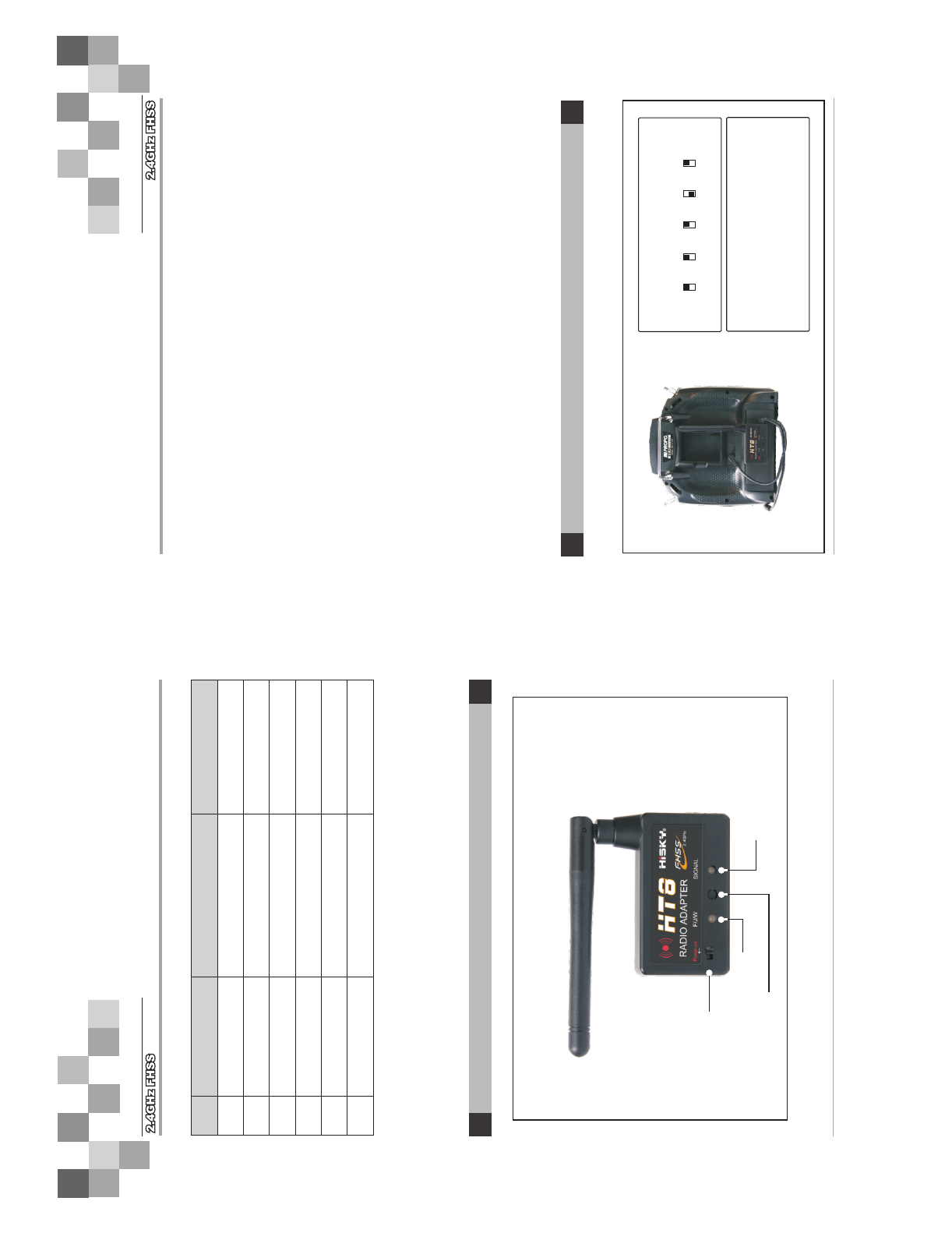
charge
binding
Internal power
supply switch
Mode indicator light: F/J/other
(Also use to indicate charging status)
Mode selector button
Signal indicator light
(Red: signal disable/Charging;
Green: Signal enable/ low power)
1. RF MODULE CHART
2. Parameters
Sealed battery Specification: 3.7V Li-Po battery 120mAh
Operating voltage: 5 ~ 12V.DC
Operating Current: ≤ 100 mA
Operating frequency: 2402 MHZ ~ 2480 MHZ
Number of frequency channels: 1
3. Charging operation:
First put the Internal power supply switch to OFF position, no LED lights on RF Module bright this
time, then connect RF Module to a computer (or the other power supplier equipment) using USB
wire, this time, Signal indicator light starts to flash and Mode indicator light shows charging status:
red means charging,turning to green means charging is over.
4. Normal use operation:
1.Supplying power of radio itself (eg:JR / Futaba) the HT-8 internal power supply switch to OFF
state.Properly connected HT-8's signal cables and power cables.(JR signal cable connecting
the remote control DSC interface,and power cable to connect to DC charging port ) (Futaba's
connection is a combination of signal cable and power cable to connect simulator interface)
2.IF no power from radio,switch the HT-8 internal power supply to on state.
properly connected HT-8 and remote control of the DSC interface.
3.Under normal circumstances the HT-8 light is green, when red check the signal cable if is
normal,as well as check the remote control to set the modulation mode to PPM format.Set the
types of remote control through switch the button of HT-8, the status indicator (Model),Futaba
(green) JR (ed). WAKERA (no light).
Notice:
1.There is one 3.7 V Li-po Battery sealed in the RF Module. If the radio controller you use can
supply the power to the RF Module, please turn off the sealed battery to off status.
2. Please pay attention to the battery power when you use sealed battery of RF Module, if the
green light is flashing, please stop to play and charge the battery.
5.Advice parameters to RF Module
1. Advice parameters to RF Module with JR radio controller
Fist, set JR radio controller to Plane Mode, then adjust the radio controller to PPM transmit format.
JR radio controller
THR AIL ELE RUD GER
[REV SW]
[TRVL ADJ]
THRO H 100% L 100%
AILE L 100% R 100%
ELEV D 100% U 100%
RUDD L 120% R 120%
GEAR + 100% - 100%