Guangzhou Chiyuan Electronic HT8 Quadcopter RF Module User Manual Manual 1 2
Guangzhou Chiyuan Electronic Co.,Ltd Quadcopter RF Module Manual 1 2
UserManual.wiki
>
Guangzhou Chiyuan Electronic
>
HT8 User Manual
>
Manual 1-2
Contents
1.
Manual 1-2
2.
Manual 2-2
Manual 1-2
Navigation menu
Upload a User Manual
Namespaces
Wiki Guide
HTML
PDF
Info
Views
User Manual
Discussion / Help
Navigation

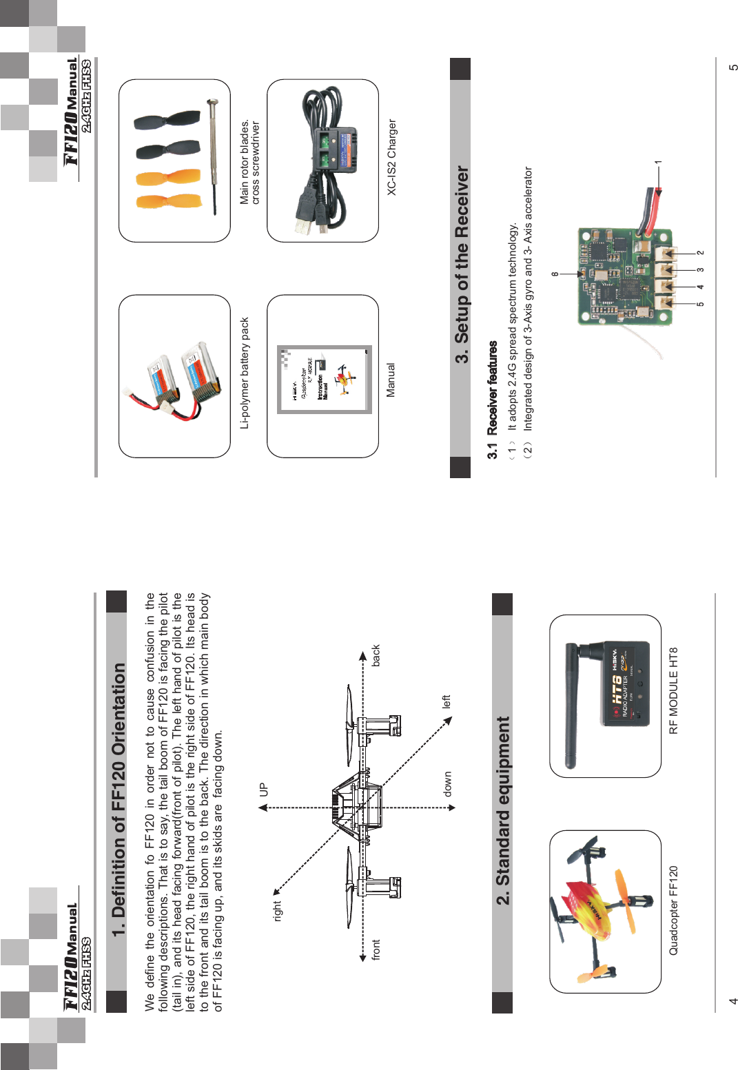
![3.2 Function of receiverNote: 4. RF MODULE INSTRUCTION6 7 ManualFf120 ManualFf120S/N Name of short Full name Function1 Power wire Connect to the lipo battery2 Right front motor3 Right back motor4 Left back motor5 Left front motor6 Signal indicator light Show the bind status(green)The bind plug face towards rightConnect to the right front motor wireConnect to the right back motor wire The bind plug face towards right Connect to the left back motor wire The bind plug face towards right Connect to the left front motor wire The bind plug face towards right Green light: When in the code paring status, the receiver indicator will flash green,;After code paring successfully the green light turns solid; If the green light turns off means failure bind or has not receive the signal.chargebindingInternal power supply switchMode indicator light: F/J/other (Also use to indicate charging status)Mode selector buttonSignal indicator light (Red: signal disable/Charging;Green: Signal enable/ low power) 1. RF MODULE CHART2. ParametersSealed battery Specification: 3.7V Li-Po battery 120mAh Operating voltage: 5 ~ 12V.DCOperating Current: ≤ 100 mAOperating frequency: 2402 MHZ ~ 2480 MHZNumber of frequency channels: 13. Charging operation:First put the Internal power supply switch to OFF position, no LED lights on RF Module bright thistime, then connect RF Module to a computer (or the other power supplier equipment) using USBwire, this time, Signal indicator light starts to flash and Mode indicator light shows charging status: red means charging,turning to green means charging is over.4. Normal use operation:1.Supplying power of radio itself (eg:JR / Futaba) the HT-8 internal power supply switch to OFF state.Properly connected HT-8's signal cables and power cables.(JR signal cable connecting the remote control DSC interface,and power cable to connect to DC charging port ) (Futaba's connection is a combination of signal cable and power cable to connect simulator interface)2.IF no power from radio,switch the HT-8 internal power supply to on state.properly connected HT-8 and remote control of the DSC interface.3.Under normal circumstances the HT-8 light is green, when red check the signal cable if is normal,as well as check the remote control to set the modulation mode to PPM format.Set the types of remote control through switch the button of HT-8, the status indicator (Model),Futaba (green) JR (ed). WAKERA (no light). Notice:1.There is one 3.7 V Li-po Battery sealed in the RF Module. If the radio controller you use can supply the power to the RF Module, please turn off the sealed battery to off status.2. Please pay attention to the battery power when you use sealed battery of RF Module, if the green light is flashing, please stop to play and charge the battery.5.Advice parameters to RF Module 1. Advice parameters to RF Module with JR radio controllerFist, set JR radio controller to Plane Mode, then adjust the radio controller to PPM transmit format.JR radio controllerTHR AIL ELE RUD GER[REV SW][TRVL ADJ]THRO H 100% L 100%AILE L 100% R 100%ELEV D 100% U 100%RUDD L 120% R 120%GEAR + 100% - 100%](https://usermanual.wiki/Guangzhou-Chiyuan-Electronic/HT8.Manual-1-2/User-Guide-1884107-Page-5.png)