Guangzhou Chiyuan Electronic N-4QA Radio Control System User Manual
Guangzhou Chiyuan Electronic Co.,Ltd Radio Control System Users Manual
UserManual.wiki
>
Guangzhou Chiyuan Electronic
>
N 4QA User Manual
Users Manual
Navigation menu
Upload a User Manual
Namespaces
Wiki Guide
HTML
PDF
Info
Views
User Manual
Discussion / Help
Navigation
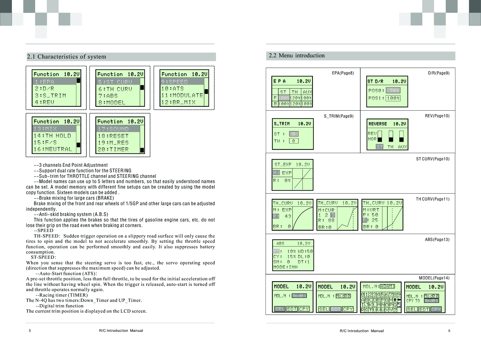
![M I X 1 0 . 2 V M I X 1 0 . 2 V : L 5 0 R 5 0T H : L 5 0 R 5 0E N : O N O F FS TR/C Introduction Manual 8 E P A 1 0 . 2 V E P A 1 0 . 2 V S T T H A U X 120%100%1 0 0 %2.4 EPAFB!Use this when performing left and right steering angle adjustments, throttle high side/brake side operation amount adjustment, and channel 3 servo up side/down side operation amount adjustment during linkage.!EPA adjusting value range: 0~120 %, default is 100%1.Press “ENTER” in the power on interface and enter function menu. Press “+” or “-” to choose “EPA”. And press “ENTER” and enter EPA adjusting interface.2.Press “ENTER” to choose each adjusting item, and then press “+” to increase and “-” to decrease the value of the corresponding item.3.Press “EXIT” to save your setting and leave EPA interface, and back to the function menu interface.TERMS: F-FORWARD,B-BACK,ST-STEERIN,TH-THROTTLE,AUX-AUXILLIARYSERVO050%100%120%50%100%120%RIGHTFWDLEFTBACKR/C Introduction Manual72.3 Main-Menu Function10.2v D/R: 7 0HLD: O F F MOD: H R FS T . T H . VoltageModel NameTimerSteering TrimThrottle Trim ModulationThrottle HoldSteering Dual RateM00:mod00T_I:00:00 F u n c t i o n 1 0 . 2 V F u n c t i o n 1 0 . 2 V 1:EPA 2:D/R3 : S _ T R I M4 : R E V 1 0 0 % 1 2 0 % 1 0 0 % E P A 1 0 . 2 V E P A 1 0 . 2 V S T T H A U X 120%100%80%FB 100%120%100% S P E E D 1 0 . 2 V S P E E D 1 0 . 2 V S T T H S P D . F L : 0 %S P D . B K : 0 % S P E E D 1 0 . 2 V S P E E D 1 0 . 2 V S T T H S P D . F L : 0 %A T S 1 0 . 2 V A T S 1 0 . 2 V TRI: 1 %P O S : 0 %D L Y : 0M O D : I N HA T S 1 0 . 2 V A T S 1 0 . 2 V TRI: 1 %P O S : 0 %D L Y : 0M O D : A C T MOD RST M O D U L A T E 1 0 . 2 V S E T R F C O M [ ] [ Y E S ]N O MOD RST M O D U L A T E 1 0 . 2 V S E T R F C O M [ N O ] [ ]Y E SS E T O K .B K - M I X 1 0 . 2 V : 8 0 %E N : O N O F FR A T EM I X 1 0 . 2 V M I X 1 0 . 2 V T H : L 5 0 R 5 0: L 6 0 R 5 0E N : O N O F FA U X F / S 1 0 . 2 VS T : 0 % T H : 0 % I N H E N : O N O F FACT F / S 1 0 . 2 VS T : 0 % A C T T H : 2 0 % E N : O N O F FI N H T H H O L D 1 0 . 2 V VALUE: 0 % T H . H O L D : N e u t r a l 1 0 . 2 VN O Y E SR E A D YS e t N eutral? N e u t r a l 1 0 . 2 VN O O KY E SSet Neutral? S O U N D 1 0 . 2 V S O U N D : I N H S O U N D 1 0 . 2 V S O U N D : A C T S YSTEM R ESE T ING . . . S YSTEM R ese t S yst e m ? M _ R E S 1 0 . 2 V R e s e t D A T A ? N O Y E SR E A D Y M _ R E S 1 0 . 2 V R e s e t D A T A ? N O O KYES T I M E R 1 0 . 2 V T : 0 m 0 s MODE: I N H T I M E R 1 0 . 2 V T : 3 m 2 s MODE: D N_T ATS(Page17)BK_MIX(Page19)TH HOLD(Page20)NEUTRAL(Page21)SYSTEM(Page22)TIMER(Page23)SPEED(Page15)MODULATE(Page18)MIX(Page19)F/S(Page21)SOUND(Page22)M_RES(Page22)](https://usermanual.wiki/Guangzhou-Chiyuan-Electronic/N-4QA/User-Guide-1239132-Page-6.png)
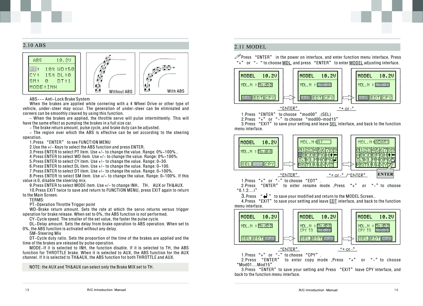
![R/C Introduction Manual 182.14 MODULATE MOD RST M O D U L A T E 1 0 . 2 V S E T R F C O M [ ] [ Y E S ]N O--Select this function to set the ID code between the N-4Q and the XY300 receiver.1.Press “ENTER” to see FUNCTION MENU2.Use the +/- Keys to select the MODULATE function and press ENTER.3.Use the +/- Keys to select YES .4.Press ENTER to see SETTING… 5.Press EXIT to return to FUNCTION MENU, press EXIT again to return to the Main Screen.Remark:1 Before setting ID Code, Please plug the short jack into the first channel of the receiver and then turn on the receiver power, The receiver will come into the set ID Code mode.2 When set ID Code is OK, the “SET OK ” is displayed on the LCD. Otherwise “SET ERR” will be displayed on the LCD. R/C Introduction Manual172.13 ATSATS Automatic StartWhen the throttle trigger is set to full throttle simultaneously with starting when the track is slippery, the car wheels will spin and the car will not accelerate smoothly. When the Start function is activated, merely operating the throttle trigger slowly causes the throttle servo to automatically switch from the set throttle position to a preset point so that the tires do no loose their grip and the car accelerates smoothly.Throttle without ATS Throttle with ATS- When the throttle trigger is moved to the preset trigger position (TRI), the throttle servo moves to the preset position (POS).- When the throttle trigger is operated slowly so that the wheels will not spin, the car automatically accelerates to the set speed.- This function is effective only for the first throttle trigger operation at starting. This function has to be activated before every start.- When the throttle trigger is returned slightly, the Start function is automatically deactivated and the set returns to normal throttle trigger operation.1.Press “ENTER” to see FUNCTION MENU2.Use the +/- Keys to select the ATS function and press ENTER.3.Press ENTER to select TRI item. Use +/- to change the value. Range: -100%~+100%..4.Press ENTER to select POS item. Use +/- to change the value. Range: 0%~100%.5.Press ENTER to select DLY item. Use +/- to change the value. Range: 0~100.6.Press ENTER to select MOD item. Use +/- to change INH or RDY.7.Press EXIT twice to save and return to FUNCTION MENU, press EXIT again to return to the Main Screen.TERMS:TRI--- Throttle trigger position.POS---Preset positionDLY---ATS Delay timeMOD---ATS Ready settingA T S 1 0 . 2 V A T S 1 0 . 2 V TRI: 1 %P O S : 0 %D L Y : 0MOD: INH F u n c t i o n 1 0 . 2 V F u n c t i o n 1 0 . 2 V 9 : S P E E D 1 1 : M O D U L A T E1 2 : B R _ M I X 1 0 : A T SA T S 1 0 . 2 V A T S 1 0 . 2 V TRI: 1 %P O S : 0 %D L Y : 0MOD: ACT F u n c t i o n 1 0 . 2 V F u n c t i o n 1 0 . 2 V 9 : S P E E D 10:ATS1 2 : B R _ M I X 11:MODULATE MOD RST M O D U L A T E 1 0 . 2 V S E T R F C O M [ N O ] [ ]YESSET OK.](https://usermanual.wiki/Guangzhou-Chiyuan-Electronic/N-4QA/User-Guide-1239132-Page-11.png)