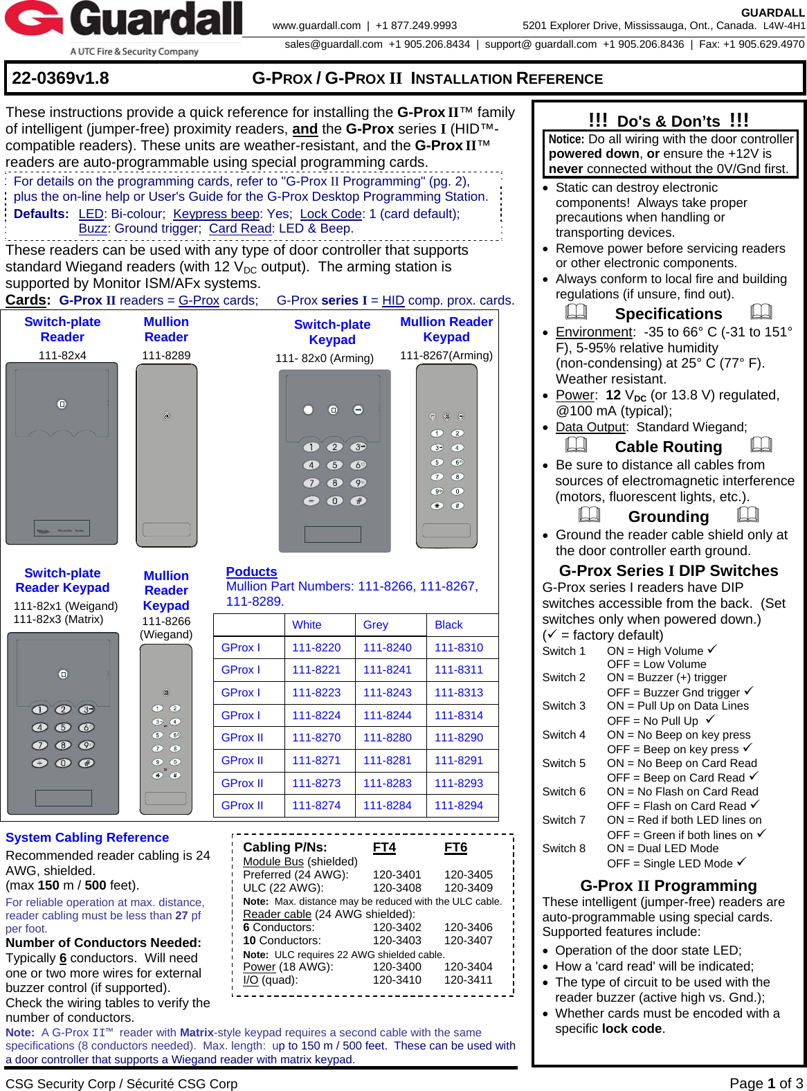
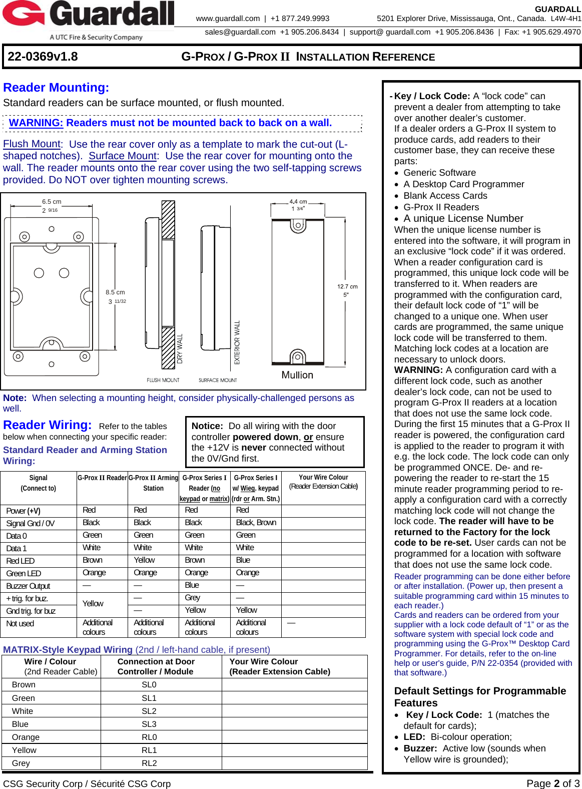
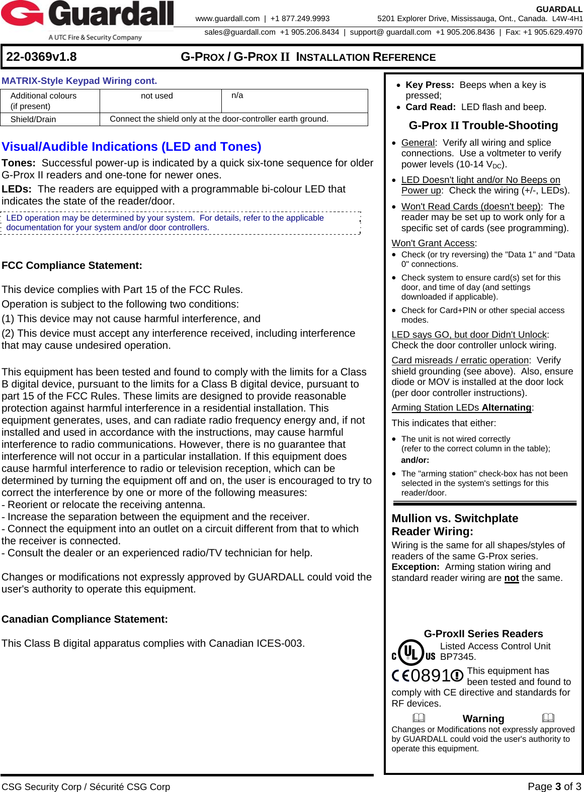
Guardall a division of CSG Security SP2A GProx II Switchplate Reader Keypad User Manual

Guardall, a division of CSG Security Corp GProx II Switchplate Reader Keypad

User Manual

    22-0369v1.8  G-PROX / G-PROX II INSTALLATION REFERENCE  CSG Security Corp / Sécurité CSG Corp Page 1 of 3  GUARDALL 5201 Explorer Drive, Mississauga, Ont., Canada.  L4W-4H1sales@guardall.com  +1 905.206.8434  |  support@ guardall.com  +1 905.206.8436  |  Fax: +1 905.629.4970www.guardall.com  |  +1 877.249.9993 These instructions provide a quick reference for installing the G-Prox II™ family of intelligent (jumper-free) proximity readers, and the G-Prox series I (HID™-compatible readers). These units are weather-resistant, and the G-Prox II™ readers are auto-programmable using special programming cards.   These readers can be used with any type of door controller that supports standard Wiegand readers (with 12 VDC output).  The arming station is supported by Monitor ISM/AFx systems.   Cards:  G-Prox II readers = G-Prox cards;     G-Prox series I = HID comp. prox. cards. Switch-plate Reader 111-82x4  Mullion  Reader 111-8289    Switch-plate Keypad 111- 82x0 (Arming) Mullion ReaderKeypad 111-8267(Arming) Switch-plate Reader Keypad  111-82x1 (Weigand)  111-82x3 (Matrix)  Mullion Reader Keypad 111-8266 (Wiegand)  Poducts   Mullion Part Numbers: 111-8266, 111-8267,  111-8289.   White Grey Black GProx I  111-8220  111-8240  111-8310 GProx I  111-8221  111-8241  111-8311 GProx I  111-8223  111-8243  111-8313 GProx I  111-8224  111-8244  111-8314 GProx II  111-8270  111-8280  111-8290 GProx II  111-8271  111-8281  111-8291 GProx II  111-8273  111-8283  111-8293 GProx II  111-8274  111-8284  111-8294   System Cabling Reference Recommended reader cabling is 24 AWG, shielded.   (max 150 m / 500 feet). For reliable operation at max. distance, reader cabling must be less than 27 pf per foot. Number of Conductors Needed: Typically 6 conductors.  Will need one or two more wires for external buzzer control (if supported). Check the wiring tables to verify the number of conductors. Note:  A G-Prox II™ reader with Matrix-style keypad requires a second cable with the same specifications (8 conductors needed).  Max. length:  up to 150 m / 500 feet.  These can be used with a door controller that supports a Wiegand reader with matrix keypad. !!!  Do's & Don’ts  !!!  Notice: Do all wiring with the door controller powered down, or ensure the +12V is never connected without the 0V/Gnd first. •  Static can destroy electronic components!  Always take proper precautions when handling or transporting devices. •  Remove power before servicing readers or other electronic components. •  Always conform to local fire and building regulations (if unsure, find out).       Specifications       • Environment:  -35 to 66° C (-31 to 151° F), 5-95% relative humidity (non-condensing) at 25° C (77° F). Weather resistant. • Power:  12 VDC (or 13.8 V) regulated, @100 mA (typical); • Data Output:  Standard Wiegand;       Cable Routing       • Be sure to distance all cables from sources of electromagnetic interference (motors, fluorescent lights, etc.).       Grounding       • Ground the reader cable shield only at the door controller earth ground. G-Prox Series I DIP Switches   G-Prox series I readers have DIP switches accessible from the back.  (Set switches only when powered down.) (9 = factory default) Switch 1  ON = High Volume 9   OFF = Low Volume Switch 2  ON = Buzzer (+) trigger   OFF = Buzzer Gnd trigger 9 Switch 3  ON = Pull Up on Data Lines   OFF = No Pull Up  9 Switch 4  ON = No Beep on key press   OFF = Beep on key press 9 Switch 5  ON = No Beep on Card Read   OFF = Beep on Card Read 9 Switch 6  ON = No Flash on Card Read   OFF = Flash on Card Read 9 Switch 7  ON = Red if both LED lines on   OFF = Green if both lines on 9 Switch 8  ON = Dual LED Mode   OFF = Single LED Mode 9 G-Prox II Programming These intelligent (jumper-free) readers are auto-programmable using special cards.  Supported features include: •  Operation of the door state LED; •  How a 'card read' will be indicated; •  The type of circuit to be used with the          reader buzzer (active high vs. Gnd.); •  Whether cards must be encoded with a  specific lock code. For details on the programming cards, refer to "G-Prox II Programming" (pg. 2), plus the on-line help or User's Guide for the G-Prox Desktop Programming Station. Defaults:  LED: Bi-colour;  Keypress beep: Yes;  Lock Code: 1 (card default);    Buzz: Ground trigger;  Card Read: LED & Beep. Cabling P/Ns: FT4 FT6 Module Bus (shielded) Preferred (24 AWG):  120-3401  120-3405 ULC (22 AWG):  120-3408  120-3409 Note:  Max. distance may be reduced with the ULC cable. Reader cable (24 AWG shielded): 6 Conductors:  120-3402  120-3406 10 Conductors:  120-3403  120-3407 Note:  ULC requires 22 AWG shielded cable. Power (18 AWG):  120-3400  120-3404 I/O (quad):  120-3410  120-3411
    22-0369v1.8  G-PROX / G-PROX II INSTALLATION REFERENCE  CSG Security Corp / Sécurité CSG Corp Page 2 of 3  GUARDALL 5201 Explorer Drive, Mississauga, Ont., Canada.  L4W-4H1sales@guardall.com  +1 905.206.8434  |  support@ guardall.com  +1 905.206.8436  |  Fax: +1 905.629.4970www.guardall.com  |  +1 877.249.9993  Reader Mounting:   Standard readers can be surface mounted, or flush mounted. Flush Mount:  Use the rear cover only as a template to mark the cut-out (L-shaped notches).  Surface Mount:  Use the rear cover for mounting onto the wall. The reader mounts onto the rear cover using the two self-tapping screws provided. Do NOT over tighten mounting screws.   6.5 cm8.5 cm239/1611/32                          Note:  When selecting a mounting height, consider physically-challenged persons as well. Reader Wiring:  Refer to the tables below when connecting your specific reader: Standard Reader and Arming Station Wiring: Notice:  Do all wiring with the door controller powered down, or ensure the +12V is never connected without the 0V/Gnd first.  Signal (Connect to) G-Prox II Reader G-Prox II Arming Station G-Prox Series I Reader (no keypad or matrix) G-Prox Series I  w/ Wieg. keypad (rdr or Arm. Stn.) Your Wire Colour (Reader Extension Cable) Power (+V) Red Red Red Red  Signal Gnd / 0V  Black Black Black Black, Brown  Data 0  Green Green Green Green  Data 1  White White White White  Red LED  Brown Yellow Brown Blue   Green LED  Orange Orange Orange Orange  Buzzer Output  — — Blue —  + trig. for buz.  — Grey —  Gnd trig. for buz  Yellow  — Yellow Yellow  Not used  Additional colours   Additional colours   Additional colours   Additional colours   — MATRIX-Style Keypad Wiring (2nd / left-hand cable, if present) Wire / Colour (2nd Reader Cable) Connection at Door   Controller / Module  Your Wire Colour (Reader Extension Cable) Brown SL0  Green SL1  White SL2  Blue SL3  Orange RL0  Yellow RL1  Grey RL2    - Key / Lock Code: A “lock code” can prevent a dealer from attempting to take over another dealer’s customer.  If a dealer orders a G-Prox II system to produce cards, add readers to their customer base, they can receive these parts:  • Generic Software  •  A Desktop Card Programmer  • Blank Access Cards  •  G-Prox II Readers  • A unique License Number   When the unique license number is entered into the software, it will program in an exclusive “lock code” if it was ordered.   When a reader configuration card is programmed, this unique lock code will be transferred to it. When readers are programmed with the configuration card, their default lock code of “1” will be changed to a unique one. When user cards are programmed, the same unique lock code will be transferred to them. Matching lock codes at a location are necessary to unlock doors.  WARNING: A configuration card with a different lock code, such as another dealer’s lock code, can not be used to program G-Prox II readers at a location that does not use the same lock code. During the first 15 minutes that a G-Prox II reader is powered, the configuration card is applied to the reader to program it with e.g. the lock code. The lock code can only be programmed ONCE. De- and re-powering the reader to re-start the 15 minute reader programming period to re-apply a configuration card with a correctly matching lock code will not change the lock code. The reader will have to be returned to the Factory for the lock code to be re-set. User cards can not be programmed for a location with software that does not use the same lock code.   Reader programming can be done either before or after installation. (Power up, then present a suitable programming card within 15 minutes to each reader.)   Cards and readers can be ordered from your supplier with a lock code default of “1” or as the software system with special lock code and programming using the G-Prox™ Desktop Card Programmer. For details, refer to the on-line help or user's guide, P/N 22-0354 (provided with that software.)    Default Settings for Programmable Features   •  Key / Lock Code:  1 (matches the default for cards);  • LED:  Bi-colour operation;  • Buzzer:  Active low (sounds when Yellow wire is grounded); WARNING: Readers must not be mounted back to back on a wall.
    22-0369v1.8  G-PROX / G-PROX II INSTALLATION REFERENCE  CSG Security Corp / Sécurité CSG Corp Page 3 of 3  GUARDALL 5201 Explorer Drive, Mississauga, Ont., Canada.  L4W-4H1sales@guardall.com  +1 905.206.8434  |  support@ guardall.com  +1 905.206.8436  |  Fax: +1 905.629.4970www.guardall.com  |  +1 877.249.9993 MATRIX-Style Keypad Wiring cont. Additional colours  (if present) not used  n/a Shield/Drain  Connect the shield only at the door-controller earth ground.  Visual/Audible Indications (LED and Tones) Tones:  Successful power-up is indicated by a quick six-tone sequence for older G-Prox II readers and one-tone for newer ones. LEDs:  The readers are equipped with a programmable bi-colour LED that indicates the state of the reader/door.    FCC Compliance Statement:   This device complies with Part 15 of the FCC Rules.  Operation is subject to the following two conditions: (1) This device may not cause harmful interference, and  (2) This device must accept any interference received, including interference that may cause undesired operation.  This equipment has been tested and found to comply with the limits for a Class B digital device, pursuant to the limits for a Class B digital device, pursuant to part 15 of the FCC Rules. These limits are designed to provide reasonable protection against harmful interference in a residential installation. This equipment generates, uses, and can radiate radio frequency energy and, if not installed and used in accordance with the instructions, may cause harmful interference to radio communications. However, there is no guarantee that interference will not occur in a particular installation. If this equipment does cause harmful interference to radio or television reception, which can be determined by turning the equipment off and on, the user is encouraged to try to correct the interference by one or more of the following measures: - Reorient or relocate the receiving antenna. - Increase the separation between the equipment and the receiver. - Connect the equipment into an outlet on a circuit different from that to which the receiver is connected. - Consult the dealer or an experienced radio/TV technician for help.  Changes or modifications not expressly approved by GUARDALL could void the user's authority to operate this equipment.  Canadian Compliance Statement:  This Class B digital apparatus complies with Canadian ICES-003.    • Key Press:  Beeps when a key is pressed;  • Card Read:  LED flash and beep. G-Prox II Trouble-Shooting • General:  Verify all wiring and splice connections.  Use a voltmeter to verify power levels (10-14 VDC). •  LED Doesn't light and/or No Beeps on Power up:  Check the wiring (+/-, LEDs). •  Won't Read Cards (doesn't beep):  The reader may be set up to work only for a specific set of cards (see programming). Won't Grant Access: • Check (or try reversing) the "Data 1" and "Data 0" connections. • Check system to ensure card(s) set for this door, and time of day (and settings downloaded if applicable). • Check for Card+PIN or other special access modes. LED says GO, but door Didn't Unlock:  Check the door controller unlock wiring. Card misreads / erratic operation:  Verify shield grounding (see above).  Also, ensure diode or MOV is installed at the door lock (per door controller instructions). Arming Station LEDs Alternating: This indicates that either: • The unit is not wired correctly  (refer to the correct column in the table);  and/or: • The "arming station" check-box has not been selected in the system's settings for this reader/door.  Mullion vs. Switchplate  Reader Wiring: Wiring is the same for all shapes/styles of readers of the same G-Prox series.  Exception:  Arming station wiring and standard reader wiring are not the same.     G-ProxII Series Readers    Listed Access Control Unit  BP7345.    This equipment has   been tested and found to comply with CE directive and standards for RF devices.               Warning               Changes or Modifications not expressly approved by GUARDALL could void the user's authority to operate this equipment. 0891LED operation may be determined by your system.  For details, refer to the applicable documentation for your system and/or door controllers.

Navigation menu