L 20 S USA RB Version 8 2014 LAVINA
2016-06-14
: Guide 2014 Lavina 20-S Usa Rb Version 8 2014 LAVINA 20-S USA RB version 8 SUNBELT LAVINA S SERIES 2016 Lavina manuals Niagara-Library
Open the PDF directly: View PDF ![]() .
.
Page Count: 32
LAVINA® 20-S User Manual
Tech Support Line: 800-987-8403 | www.superabrasive.com | info@superabrasive.us
Superabrasive UserManual OriginalLanguageLavina®20‐S 8/2014
2
Superabrasive UserManual OriginalLanguageLavina®20‐S 8/2014
3
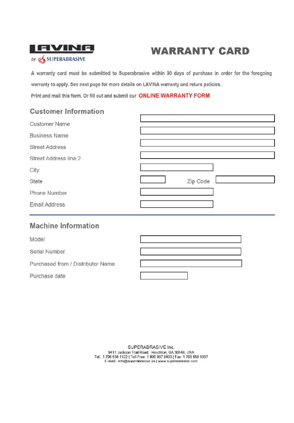
WARRANTY AND RETURNS
WARRANTY POLICY FOR LAVINA® S MACHINES
A warranty card must be submitted to Superabrasive within 30 days of purchase in order for the foregoing warranty to
apply.
You can either mail a hard copy of the warranty card or submit it electronically - see page 2.
Superabrasive warrants, from the time of delivery and receipt by the original customer, new and unused products
sold by
Superabrasive or Superabrasive-appointed distributors or dealers. Goods shall be free from defects in
materials and
workmanship. Superabrasive or a Superabrasive-appointed repair facility shall either replace or
repair any defects in the
Goods resulting from faulty design, materials, or workmanship. Products repaired or
replaced during the warranty period
shall be covered by the foregoing warranty for the remainder of the original
warranty period, or ninety (90) days from date
of the repair or shipment of the replacement, whichever is longer.
Spare parts for repair will be either new or equivalent to
new.
Warranty period shall be 2 years from the time of delivery and receipt by the original customer, or 600 operating
hours on
the machine - whichever occurs first. Superabrasive will cover the shipping charges for the transportation
of the machine to
Superabrasive (or an approved repair facility) and back to the customer (within the contiguous 48
United States) in the event
that the damage occurs and is reported within the first 90 days or 200 operating hours -
whichever occurs first. Shipping
charges, if covered by Superabrasive, must be agreed upon in advance and
approved by Superabrasive. Thereafter, the
customer will have to cover the shipping charges to Superabrasive and
back. Superabrasive will not warranty Goods after a
period of 2 years from the time of delivery and receipt by the
original customer, or 600 operating hours on the machine -
whichever occurs first.
Superabrasive shall not be liable for any defects that are caused by circumstances that occur after the Goods
have been
delivered and whilst the Goods are in the possession of the purchaser. Furthermore, the warranty
does not include normal
wear and tear or deterioration. Wear parts are not warranted. Superabrasive is not liable
for defects arising out of use of
non-OEM parts.
The Warranty is void if the purchaser has not followed the maintenance plan stipulated by the machine’s manual
and
warranty card. The warranty is void if the purchaser repairs said Goods himself, or if repairs are conducted by a
repair facility
that is not approved by Superabrasive. Superabrasive’s liability does not cover defects which are
caused by faulty
maintenance, incorrect operation, faulty repair by the purchaser, or by alterations conducted
without Superabrasive’s prior
written consent. The same applies to any alterations of the Goods or services
performed by another party other than
Superabrasive, a Superabrasive-appointed distributor, or a Superabrasive-
approved repair facility. The warranty is not
applicable on a defect that arises due to tools or parts that are not
original to Superabrasive. Replaced defective parts shall
be placed at Superabrasive’s disposal and shall become
property of Superabrasive. If such defective parts are replaced
within the warranty period, the shipping charges will be covered by Superabrasive. In warranty complaint cases,
when no
defects are found for which Superabrasive is liable, Superabrasive shall be entitled to compensation for
the labor, material
cost, and shipping charges, incurred by Superabrasive as as a result of the complaint.
The warranty herein is non-transferable, and only applies to the original owner or purchaser of the machine.
RETURN POLICY FOR LAVINA® S MACHINES
The Lavina® S machines may be returned, subject to the following terms:
In no case, a machine is to be returned to Superabrasive Inc. for credit or repair without prior authorization.
Please contact
Superabrasive Inc. or your local distributor for an authorization and issuance of a return
authorization number. This number
along with the serial number of the machine must be included on all packages
and correspondence. Machines returned
without prior authorization will remain property of the sender and
Superabrasive Inc. will not be responsible for them. No
machines will be credited after 90 days from the date of
invoice.
All returns must be shipped freight prepaid. Returned machines may be exchanged for other equipment or parts of
equal
dollar value. If machines are not exchanged, they are subject to a fifteen percent (15%) restocking fee.
Superabrasive UserManual OriginalLanguageLavina®20‐S 8/2014
4
WARRANTYANDRETURNS............................................................3
1.GENERALINFORMATION............................................................5
MANUFACTURER...........................................................................5
GENERALDESCRIPTION..................................................................5
MACHINECHARACTERISTICS..........................................................5
MAINDESIGN.................................................................................5
ENVIRONMENTALCONDITIONS.....................................................5
ELECTRICALCONNECTION..............................................................5
VACUUMCONNECTION.................................................................6
TECHNICALDATA...........................................................................6
VIBRATIONS...................................................................................6
2.SAFETYINSTRUCTIONS...............................................................6
RECOMMENDEDUSE.....................................................................6
PROHIBITEDUSE............................................................................6
FEATUREINCLEMENTCONDITIONS................................................6
POSSESSELECTROMAGNETICRADIATION......................................6
PREPARATIONFORWORK.............................................................6
PROTECTIONDEVICES....................................................................7
ARRESTFUNCTIONS.......................................................................7
SAFEUSE........................................................................................7
RESIDUALRISKS.............................................................................7
BEFOREYOUBEGIN........................................................................7
OPERATINGMACHINE..................................................................7
AFTERWORKISCOMPLETED...........................................7
THEWORKAREA..........................................................7
PERSONALPROTECTIVE.................................................................7
EQUIPMENT(PPE)..................................................................7
OPERATOR..................................................................................7
3.HANDLINGANDTRANSPORTATION.........................................13
PREPARINGTHEMACHINEFORTRANSPORTATION.....................13
STORAGE......................................................................................13
4.OPERATION..............................................................................13
PRELIMINARYCONTROLS.............................................................13
ADJUSTINGANDMOUNTINGTOOLS...........................................14
THECONTROLBOARD..................................................................14
STARTINGTHEMACHINE.............................................................14
OPERATINGTHEMACHINE...........................................................14
STOPPINGTHEMACHINE.............................................................14
ALARM.........................................................................................14
5.TOOLSANDACCESSORIES........................................................15
WEIGHTS......................................................................................15
TOOLHOLDERKEY.......................................................................15
FOAMPLATE................................................................................15
SECURITYPLATEFORQUICKCHANGEPADS..................................15
6.POPULARTOOLS......................................................................16
RECOMMENDEDTOOLS...............................................................16
7.EXPLODEDVIEW......................................................................17
GENERALEXPLODEDVIEW(FIG.7.1)............................................17
MAINHEADEXPLODEDVIEW(FIG.7.2)........................................17
TOPCOVEREXPLODEDVIEW1(FIG.7.3)......................................17
TOPCOVEREXPLODEDVIEW2(FIG.7.4)......................................17
BOTTOMCOVEREXPLODEDVIEW1(FIG.7.5)..............................18
PLANETARYDRIVEEXPLODEDVIEW(FIG.7.6)..............................18
BOTTOMCOVEREXPLODEDVIEW2(FIG.7.7)..............................18
PULLEYUNITSEXPLODEDVIEW(FIG.7.8).....................................18
CARRIAGEEXPLODEDVIEW(FIG.7.9)...........................................18
TOOLHOLDEREXPLODEDVIEW(FIG.7.10)...................................18
8.MAINTENANCEANDINSPECTION............................................19
CLEANING....................................................................................19
CHECKDAILY................................................................................19
CHECKANDREPLACEAFTERTHEFIRST15WORKINGHOURS......19
CHECKEVERY200WORKINGHOURS...........................................19
CHECKEVERY400WORKINGHOURS...........................................19
VACUUM.....................................................................................19
WATERLEAKS..............................................................................19
MECHANICALPARTS....................................................................19
ELECTRICALSYSTEM.....................................................................19
LAVINA®20‐SELECTRICALSCHEMESWITHYASKAWAINVERTER20
9.TROUBLESHOOTING.................................................................21
INDEXOFPROBLEMSANDSOLUTIONS........................................21
9.1REPLACINGPOWERCORDANDPLUGS...................................21
9.2DISMOUNTINGANDMOUNTINGTOOLHOLDERTOCHANGE
BUFFERSANDSPIDERS,CHANGINGV‐RINGSANDFELT‐RINGS....21
9.3TENSIONINGANDREPLACETHEPLANETARYBELT.................22
9.4TENSIONINGUSEDPLANETARYBELT.....................................22
9.5MOUNTINGANDTENSIONINGANEWPLANETARYBELT.......22
9.6REPLACINGPULLEYUNITS......................................................23
9.7MOUNTINGTHEBELT.............................................................25
9.8CHECKINGTHETENSIONOFTHEBELT....................................26
9.9MOTORCONNECTION............................................................26
9.10FAULTDIAGNOSISINVERTERYASKAWAV1000...................27
10.DISPOSAL...............................................................................29
11.MANUFACTURER’SCONTACTS...............................................29
12.SPAREPARTS.........................................................................30
ASSEMBLYANDPARTSSPECIFICATIONS......................................30
1.LAVINA®20‐SGENERALPARTS/FORMACHINESPRODUCED
BEFOREJAN.12014/....................................................................30
1.LAVINA®20‐SGENERALPARTS/FORMACHINESPRODUCED
AFRTERJAN.12014/..................................................................30
2.LAVINA®20‐STOPCOVERPARTS1..........................................31
4.LAVINA®20‐STOPCOVERPARTS2..........................................31
3.LAVINA®20‐SGUARDPARTS...................................................31
5.LAVINA®20‐STOPCOVERPARTS3..........................................32
6.LAVINA®20‐SBOTTOMCOVERPARTS1..................................32
7.LAVINA®20‐SPLANETARYDRIVEPARTS..................................32
8.LAVINA®20‐SBOTTOMCOVERPARTS2..................................33
10.LAVINA®20‐STOOLHOLDERPARTS......................................34
11.LAVINA®20‐SWATERSUPPLYPARTS.....................................34
FORMACHINESPRODUCEDBEFOREJAN.12014/.......................34
11.LAVINA®20‐SWATERTANKPARTS........................................34
FORMACHINESPRODUCEDAFTERJAN.12014/.........................34
13.LAVINA®20‐SCONTROLBOXPARTS200‐240VOLT..............37
1.GENERALINFORMATION
Thisowner’smanualisintendedfortheoperatoroftheLavina®Smachine,theservicingtechnicianaswellasforanyoneinvolved
withoperatingorservicingthemachine.Werecommendthatyoureadtheinstructionsverycarefullyandfollowthemstrictly.
Themanualincludesinformationaboutassembling,using,handling,adjustingandmaintainingyourLavina®Sfloorgrindingand
polishingmachine.
MANUFACTURER
Superabrasivewasfoundedin1987,asamanufacturerofhighqualitydiamondtoolsforthestoneandconcreteindustry.Today,
Superabrasiveisoneoftheworld’sleadingcompaniesintheproductionofdiamondtoolsandfloorgrindingmachinery.At
Superabrasive,westrivetodelivertheverybestsolutionstoourcustomers,andenablethemtoworkmoreefficiently.
GENERALDESCRIPTION
TheLavina®Smachineisintendedforgrinding,polishingandbuffingconcrete,marble,granite,limestoneandterrazzosurfaces
withdiamondtools.
TheLavina®Smachineisathree‐discmachine,whichcanbeuseddryaswellaswet.
Forbestresults,useonlytoolsmanufacturedorrecommendedbySuperabrasiveanditsdistributors.Additionally,themachinecould
beusedforgrindingwoodfloorsurfaces.
TheLavina®Smachineismanufacturedandfittedfortheabove‐
mentionedapplicationsonly!Everyotherusemaycauseriskstothepersonsinvolved.
MACHINECHARACTERISTICS
TheLavina®Smachineismadeoftwomaincomponentsections:
MAINDESIGN
Thetwomaincomponentsectionsarethecarriageandmainhead.
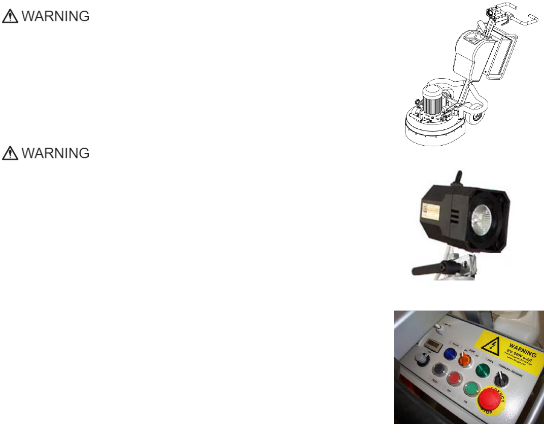
Thehandle(Fig.1.2)ontheframecanbeadjustedbyheightandallowstheoperatortoworkin
acorrectandsafeworkingposture.
Thehalogenspotlight(Fig.1.2)enablestheoperatortoworkindarkerareas.
Existinglightingsystemdoesnotreplaceadequateoverheadlighting.
Theframe
Thecontrolsarepositionedontopoftheelectricalbox(fig.1.3)
Theelectricalbox(fig.1.3)containstheelectricswitchingdevicesandthe
inverter.Themainfeedingcableisconnectedwithaplugandsocketontop.Themotor
feedingcableispluggedintothesocketlocatedonthebottomofthebox.Thetankisonthe
oppositesideoftheframe,sothattheweightofthewaterhasnoinfluenceontheoperationof
themachine.Theframeweight,ontheotherhand,isfullyabsorbedbythedrivingwheels.An
electricpumpspraysthewaterthroughafrontsprayer.Themotorismountedonthebase
plateandisdrivingthethreeheadswithabeltsystem.Theplanetaryheadisdrivenbya
secondflatbelt.
ENVIRONMENTALCONDITIONS
ThetemperaturerangeforoperatingtheLavina®Smachineoutdoorsisbetween41°Fand86°F
or5°Cand30°C.NeverusetheLavina®Smachineduringrainorsnowwhenworkingoutdoors.
Whenworkingindoors,alwaysoperatethemachineinwell‐ventilatedareas.
ELECTRICALCONNECTION
Thevoltage(Volt)andpower(Ampere)aredisplayedonalabelontheelectricalcontrolboxto
avoidanyincorrectconnection.Refertothesebeforeconnectingthepower.Toavoidelectrical
shocks,makesurethegroundpowersupplyisfunctioningproperly.
Figure 1.3
Fi
g
ure 1.1
Figure 1.2
Superabrasive UserManual OriginalLanguageLavina®20‐S 8/2014
6
VACUUMCONNECTION
Aconnectionforavacuumdustextractorislocatedonthecarriage.TheLavina®Smachinedoesnotincludeavacuumdustextractor.
Thecustomermustpurchasethevacuumdustextractorseparately.ThehoseofthevacuumextractormustbeØ50.8mmandcan
beglidedoverthepipe.Thevacuumdustextractormustbeadaptedforfloorgrindersandhaveaminimumairdisplacementof
320m3/hwithanegativevacuumof21kPa.
TechnicalData
Lavina®20‐S
Voltage/Hz 1phx200‐240V50‐60Hz
Amperage Max14 Amps
Power3kW 4HP
Toolholderrpm300‐1100rpm
Workingwidth510mm 20”
Tooldiameter(QCPlate)3x225mm 3x9”
Weight162 kg 357 lbs
Grindingpressure80 kg 177 lbs
Additionalweightmax1x22kg max1x48 lbs
Application wetanddry
VacuumhoseportYes
Watertankcapacity20 l5.2gal
Waterfeed withpump(peripheralandfront)
Cablelength17.4m57ft
MachineLxWxH1350x540x1100mm 53.1”x21.3”x43.3”
PackingLxWxH1150x730x1155mm 45.2”x28.7”x45.5”
Vibrations
ThevibrationsofthemachinearewithinthelimitsofdirectivesandharmonizedstandardsfromtheEuropeanUnionwhenthe
Lavina®Sisoperatedwiththerecommendedtoolsandinnormalconditions.
SonorousEmissions
ThesonorousemissionsarewithinthelimitsofdirectivesandharmonizedstandardsfromtheEuropeanUnionwhentheLavina®Sis
operatedwiththerecommendedtoolsandinnormalconditions.However,aspreviouslystated,theoperatormustwearear
protectors.
LabelData
ThedataonthelabelprovidesthecorrectVoltageandkW(neededforoperationalpurposes);
Weight(neededfortransportationpurposes);productionyearandserialnumber(neededformaintenancepurposes).
CustomerService
ForcustomerassistanceandtechnicalsupportcallyourlocaldistributororcallSuperabrasiveInc.at
1‐800‐987‐8403orvisitusat:www.superabrasive.com,whereyoucandownloadacopyofthismanual.
2.SAFETYINSTRUCTIONS
RECOMMENDEDUSE
TheLavina®Smachineis
designedandmanufacturedtogrindandpolishconcrete,
terrazzo,andnaturalstonefloors.Itcanbeusedforrenovations
aswellasforpolishing.Themachineisdesignedfordryorwet
use.Whenusingitdry,useavacuumofappropriatesize.For
moreinformation,pleaserefertothechapteronhandlingthe
vacuumconnection.
PROHIBITEDUSE
ThemachineMUSTNOTbeused:
ForapplicationsdifferentfromtheonesstatedintheGeneral
Descriptionchapter.
Fornon‐suitablematerials.
Inenvironmentswhich:
Possessrisksofexplosion
Possesshighconcentrationofpowdersoroilsubstancesintheair
Possessrisksoffire
Featureinclementconditions.
Possesselectromagneticradiation.
PREPARATIONFORWORK
Makesurethat:Youhaveclosedtheworkarea,sothatnoperson
unfamiliarwithoperatingthemachinecanenterthearea.Thetool
plateandtoolsareadjustedtothemachineproperly.Thereareno
missingpartsofthemachine
Themachineisinuprightworkingposition.Theprotectiondevices
areworkingproperly.Theelectricalcableisfreetomoveandfollow
themachineeasily.Inordertokeeptheelectricalcablefrombeing

Superabrasive UserManual OriginalLanguageLavina®20‐S 8/2014
7
damaged,novehicleshouldcrossthezonewhereelectrical
cablesaresituated.
PROTECTIONDEVICES
Themachineisequippedwith
severalprotectiondevicesincludingthefollowing:
Anemergencystopbutton
Aprotectionskirtandahoodforprotectingthetoolplates.
Thesedevicesprotecttheoperatorand/orotherspersonsfrom
potentialinjuries.Donotremovethem.Oncontrary,before
usingthemachine,pleaseensurethatallprotectiondevicesare
mountedandfunctionproperly.TheSecurityplateavoidthe
Quickchangepadstolooseduringwork
ARRESTFUNCTIONS
Functionsofarrestingofthe
machinearefollowing:
Buttontostopthemotor(category1)
Emergencybutton(category1)
SAFEUSE
TheLavina®Sisdesignedto
eliminateallriskscorrelatedwithitsuse.However,itisnot
possibletoeliminatetherisksofanaccidentwiththemachine.
Anunskilledoruninstructedoperatormaycausecorrelated
residualrisks.Suchrisksare:
PositionRisksduetooperator’sincorrectworkingposition
TanglingupRisksduetowearinginappropriateworkingclothes
TrainingRisksduetolackofoperationaltraining
NOTE:Inordertoreduceallconsequencesoftheabove‐
mentionedrisks,weadvisethatmachineoperatorswillfollow
theinstructionsinthemanualatalltimes.
RESIDUALRISKS
Duringthenormaloperating
andmaintenancecycles,the
operatorisexposedtofewresidualrisks,whichcannotbe
eliminatedduetothenatureoftheoperations.
BEFOREYOUBEGIN
Workingareamustbeclear
fromanydebrisorobjects.
Afirst‐timeoperatormustalwaysreadthemanualandpay
attentiontoallsafetyinstructions.
Allelectricconnectionsandcablesmustbeinspectedfor
potentialdamages.
Groundwiresystemofthepowersupplymustbealsoinspected.
Performgeneraldailyinspectionsofthemachineandinspect
themachinebeforeeachuse.
Alwaysinspectthesafetydevices:MounttheSecurityplatefor
theQuickchangepads.
Theemergencybreakmustbeclearandworking
Thetoolprotectormustbeworking
Themachinemustbeclean
Neveroperatethemachineintherain!
Confirmthattherearenomissingpartsespeciallyafter
transportation,repair,ormaintenance.
Beforefillingthewatertankwithwatermakesurethemachineis
notworkingandthemainswitchisturnedoff.
Beforeturningonthemachinemakesurethatthebaseisplaced
onthefloor,themachineMUSTNOTbeinanuprightposition
whenturnedon!
OPERATINGMACHINE
WhenoperatingtheLavina®S,makecertainthatthereisnoone,but
youaroundthemachine.
Neverleavethemachineunattendedwhileworking.
Theelectricalcablemustmovefreelyandmustbedamage‐free.
Thewaterhosemustmovefreelyandmustbedamage‐free.Checkif
thefloor,youworkon,isnottoouneven.Ifthisisthecase,itmay
damagethemachine.
AFTERWORKISCOMPLETED
Cleanthemachineanditssurroundingsproperly
Emptyandcleanthewatertank
Unplugthemachineandwinduptheelectricalcable
Storethemachineinasafeplace
THEWORKAREA
Makecertainthatpeopleorvehiclesdonotentertheworkarea.
Avoidcablesandhosesbeingintheway.
Alwayscheckthefloorfordebris
PERSONALPROTECTIVE
EQUIPMENT(PPE)
Alwayswearsafetyshoeswhenworkingwiththemachine.
Alwayswearearprotectorswhenworkingwiththemachine.All
personnelintheimmediateworkareamustwearsafetyglasses
withsideshields.
Alwayswearsafetygloveswhenchangingthetools.
Alwayswearclothessuitablefortheworkenvironment.
OPERATOR
TheLavina®Smachine.
Theoperatormustknowthemachine’sworkenvironment.
Onlyoneoperatoratatimecanworkwiththemachine.The
operatormustbeproperlytrainedandwellinstructedprior
operatingthemachine.
Theoperatormustunderstandalltheinstructionsinthis
manual.
Theoperatormustunderstandandinterpretallthedrawingsand
designsinmanual.
Theoperatormustknowallsanitationandsafetyregulations
pertainingtotheoperationofthemachine
Theoperatormusthavefloorgrindingexperience.
Theoperatormustknowwhattodoincaseofemergency.
Theoperatormusthaveanadequatetechnicalknowledgeand
preparation.
13
Superabrasive UserManual OriginalLanguageLavina®20‐S 8/2014
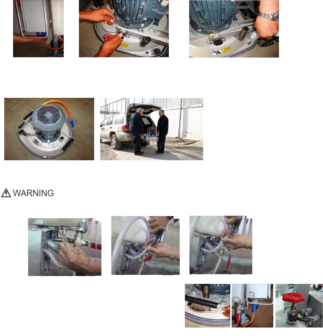
3.HANDLINGANDTRANSPORTATION
PREPARINGTHEMACHINEFORTRANSPORTATION
Unplugthemotorcableplugfromthecontrolbox(Fig.3.1)anddisconnectthewaterhosefromthemainheadbypullingitout
(Fig.3.2).Windtheelectricalcableonthecarriage.Releasethepinsets(Fig.3.3)whichattachtheheadtothecarriage.
Pulloutthevacuumhoses,anddismountthe
headfromthecarriage(Fig.3.4).
TheheadoftheLavina®Smachinehasone
barandasupportusedashandlesintended
foreasymovingandtransportation(Fig.
3.4).TheLavina®Smachineisengineered
witheasytransportationinmind.The
abilitytodismantlethemachineintwo
partsallowsconvenienttransportationand
storage(Fig.3.4,Fig.3.5).
STORAGE
AlwaysstoreandtransporttheLavina®Smachineinadryplace.NevertransporttheLavina®Smachineunprotected;itmay
bedamagediftransportedunprotectedduringrainorsnow.
Whenstoringthemachine,thetemperaturemayfalldowntoorlessthan32F(or0oC),thereforeyou
shouldemptythewaterfromthesystemusingfollowingsteps:
‐ Pulloutthehoseofthetank(Fig.3.6)
‐ Usingcompressedairblowoutthewaterfromthesystemforthetwopositionsoftheturn‐cock(Fig.3.7,Fig.3.8).
4.OPERATION
PRELIMINARYCONTROLS
Inspecttheworkingareaasexplainedinthesafetyinstructions.Forwet
use,fillinthewatertankwhentheelectricalcableisdisconnected.
Connect
thevacuumextractorandensurethatthevacuumhoseisclearandit
willfollowthemachineeasily.Pluginthemachineandmakesurethat
thepowercordisfreetofollowtheworkingdirectionoftheLavina®Smachine.
WATERFLOWCONTROLUNIT
Theoperatorcanchoosethewaterspraysinthefront(Fig.4.1)whenthelevelofthetapisinthehorizontalposition(Fig.4.2),when
thelevelisintheverticalposition(Fig.4.2)waterwillsprayundercoverofthemachine.
Theflowregulatingvalvelocatedonthetank(Fig.4.3)isincreasingorreducingthewaterflowtotheworkingarea–infrontofthe
machineorunderthemainheadcoverofthemachine/onlyformachinesproducedafterJan.12014/.
Figure 3.4 Figure 3.5
Figure 3.1 Figure 3.3
Figure 3.2
Figure 3.6 Figure 3.7 Figure 3.8
Figure 4.2 Figure 4.3
Figure 4.1
14
Superabrasive UserManual OriginalLanguageLavina®20‐S 8/2014
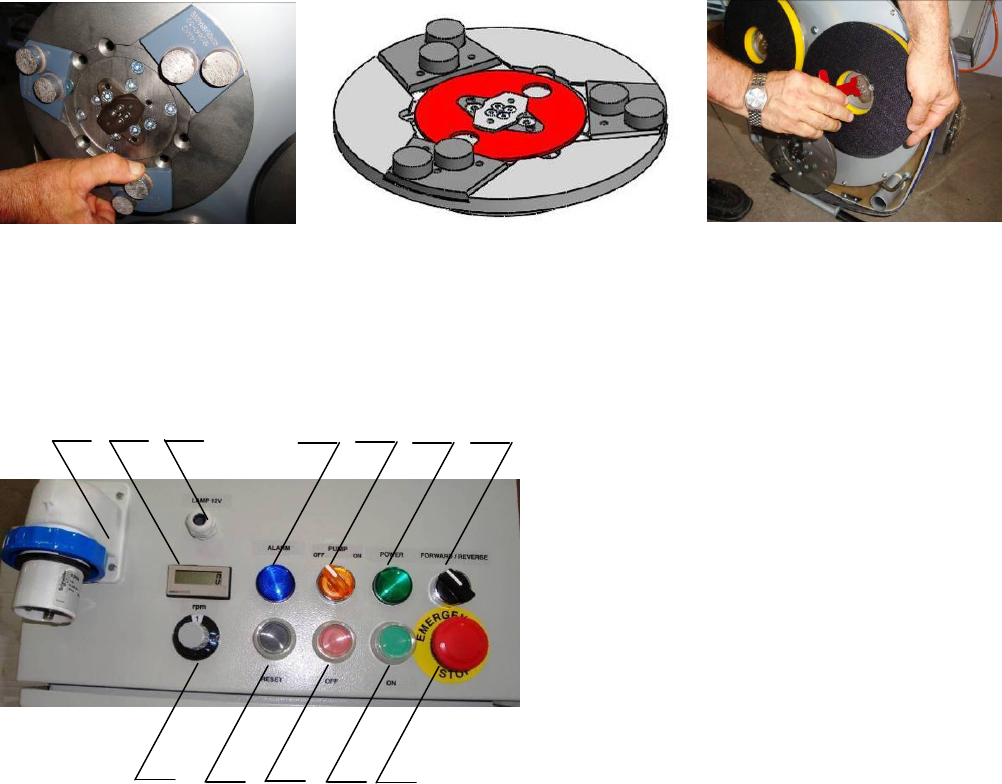
ADJUSTINGANDMOUNTINGTOOLS
Mountthetoolsonlyafterensuringthatthereisenoughdiamondbondmaterialleft.Besurethattheplatesarealwaysclean
beforemounting.(Fig.4.3)
WARNING:Alwayssecurethe“Quickchange”padswiththesecurityplate(Fig.4.3),lockwiththetoolholderkey(Fig.5.4).
DiamondtoolswithVelcroareattachedonthree9inchfoamplates.Thefoamplatesaremountedonthekeylock
(butterfly).Alwaysusethetoolholderkey(Fig.5.4).
THECONTROLBOARD
1. Powercableplug
2. DigitalRPMindicatorIndicatestherevolutionper
minuteofthegrindingplates(nottherevolutionper
minuteoftheentireunit).
3. Lampcablegland
4. InverteralarmledLightsbluewhentheinvertergoes
intoalarmmode.
5. WaterpumpswitchLightsorangewhenthewater
pumpisworking.
6. Powerledlightsgreenwhenthepowerison
7. Forward/Reverseswitchchooseforwardforclockwise
rotationofthegrindingplatesorreverseforanti‐
clockwiserotationofthegrindingplates
8. PotentiometerchangestheRPMofthegrinding
platesfrom300‐1100rpm
9. Resetbuttonresetsthealarmoftheinverter
10. OFFbuttonstopsthemotor
11. ONbuttonstartsthemotor
12. EmergencybuttonusedinEmergencysituationsfor
stoppingthemotor
STARTINGTHEMACHINE
First,followthedirectionsinchapterSafetyDevicesandSafetyInstructions.Next,pulltheemergencystop(12)toensurethatthe
machineisinworkingcondition.Checkthepotentiometer(8)andensurethatitissetattheworkingspeed.Ifworkingwet,add
watertothefloorsurface.Ifworkingdry,omitthisstep,andinstead,switchonthevacuumunit.Finally,holdthemachinefirmly
andpushthestartbutton(11).
OPERATINGTHEMACHINE
Guidethemachineinstraightlinesacrossthefloor,andwitheachnewlineoverlapalittlebitofthepreviouslycompletedsurface.
Workataconstantspeedallowingthetoolstimetoworkataspeedappropriateforthetools’gritsize.Avoidvibrations.Donotstop
theLavina®Smachineinonespotwhilethetoolsarestillworkingbecausetheywillleavemarksonthefloorsurface.Whenworking
wet,preliminarychosewiththewatertap(Fig4.2)thepositionforwaterfeedandperiodicallystartthepumptoreleasewateronto
thefloorsurface(Fig.4.6Pos.5).Whenworkingdry,checkthefloorsurfaceperiodicallytoensurethatdustisnotaccumulatingon
thesurface,alsocheckregularlythatyourvacuumworksproperly.
STOPPINGTHEMACHINE
Thestoppingofthemachinemustbedonegraduallyuntilthemotorstops.Donotstopmovingthemachinebeforearrestingthe
Motor,asthetoolscoulddamagethesurface.Tostop,pushtheoffbutton(10).UsetheEmergencybutton(13)onlyinemergency
oruseittoswitchthepowertotallyoff.Remembernottoholdthemachineinonespotbeforeturningoffthemotor.
ALARM
TheAlarmlight(4)willlightincaseinvertergoesinalarmmode.Themostcommonfailureismotorinoverload.Toresetthemode
pushresetbutton(9).
Figure 4.4 Figure 4.6
Figure 4.5
Figure 4.7
1234567
89101112
15
Superabrasive UserManual OriginalLanguageLavina®20‐S 8/2014
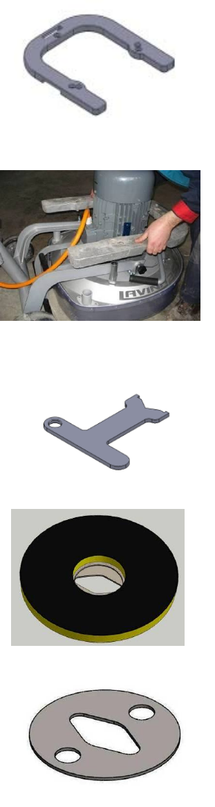
5.TOOLSANDACCESSORIES
WEIGHTS
Superabrasiveoffersadditionalweightsforincreasingtheproductivityofthemachine
(Fig.5.1).Eachadditionalweightweighsabout48lbsor22kg.Eachindividualapplication,
typeandconditionofsurface,powercapacityoftheoutlet,etc.willdeterminethenumber
ofweightsyoucanusewithout
trippingabreaker.
Theweightstacksontothreepostsaroundtheouterbowl(Fig.5.2).Theadditional
weightsdependonthetools;itisnotalwayspossibletoaddweights.Sometoolswork
tooaggressivelyandthemachinecanstop.Theweightcanbeorderedwithitemnumber
A07.00.00.00
TOOLHOLDERKEY
Thetoolholderkey(Fig.5.3)isusedforadjusting,mountinganddismountingofthefoam
plates.Alwaysusethekeyformounting.
ItemnumberisA03.00.00.00
FOAMPLATE
DiamondtoolswithVelcroaremountedonthefoamplate9“(Fig.5.4).Thefoamplateis
mountedonthe“QuickChange”System.
ItemnumberisLV‐9‐FP‐S
SECURITYPLATEFORQUICKCHANGEPADS
Plate(FIG.5.5)usedtoensurethe“QuickChange”pads.ItemnumberisA38.00.01
Fi
g
ure 5.3
Figure 5.1
Figure 5.5
Figure 5.4
Fi
g
ure 5.2
16
Superabrasive UserManual OriginalLanguageLavina®20‐S 8/2014
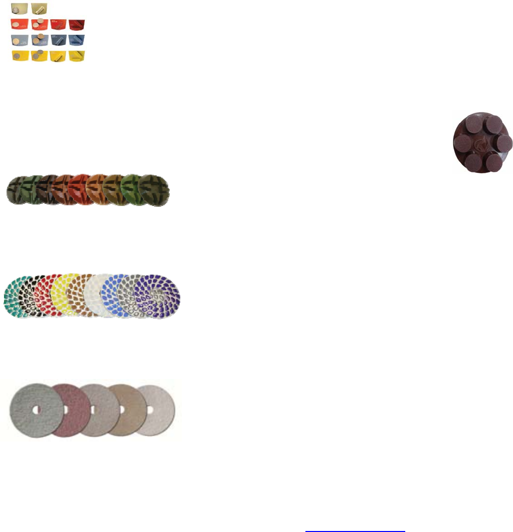
6.POPULARTOOLS
RECOMMENDEDTOOLS
QuickChangeSystemandToolingfeatureextremelyfastandconvenienttoolchanges,andalongtool
life,providingforgreatlong‐termcostsavings.TheQuickChangepadsareproducedinfourdifferent
bondsforsuperhard,hard,mediumandsoftconcrete,inavarietyofgritsizes.Theyareofferedwith
1or2buttonsorrectangularsegments,whichallowsyoutocustomizetheaggressivenessofthecut.
Calibragrindingdiscs:ourpopularceramicbonddiscsaredesignedfortheremovalofdifficultscratches
andtheysaveyouvaluabletimebyeliminatingtheneedformultiplepasseswithmetaltools.Theycanbe
used
wetordry,andarebestforhardconcreteapplications.
Theyare3‐inch,withincludedVelcrobackattachment.
NATO®polishingdiscsfeatureaspecialresinformuladesignedforbothwetanddryapplicationsandauniquedesignwith
widechannelsallowingforworkonacleanersurfaceandensuringaqualitypolish.Availablein3and4insizes.Theyarewith
includedVelcroattachment.
V‐HARR®PremiumPolishingPadsaredesignedformechanicallypolishingandrestoringconcrete;alsoidealforterrazzoand
hardstonefloors.V‐HARR®padsareofferedinawidevarietyofdiametersandgritsizestoaccommodatemanyapplications.
Dryuseisstronglyrecommended.
ShinePro®arehighqualitydiamond‐impregnatedpadsforfloormaintenance.Availableinavarietyofsizes,andaregreatfor
dailyuse.Whenusedwet,theyrequireonlywater(nowaxorchemicalsneeded)andareaveryenvironmentallyfriendlysolution
formaintainingfloors.
Useonlysuperabrasive’srecommendedtools.Formoretoolingoptions,visitwww.superabrasive.com
17
Superabrasive UserManual OriginalLanguageLavina®20‐S 8/2014
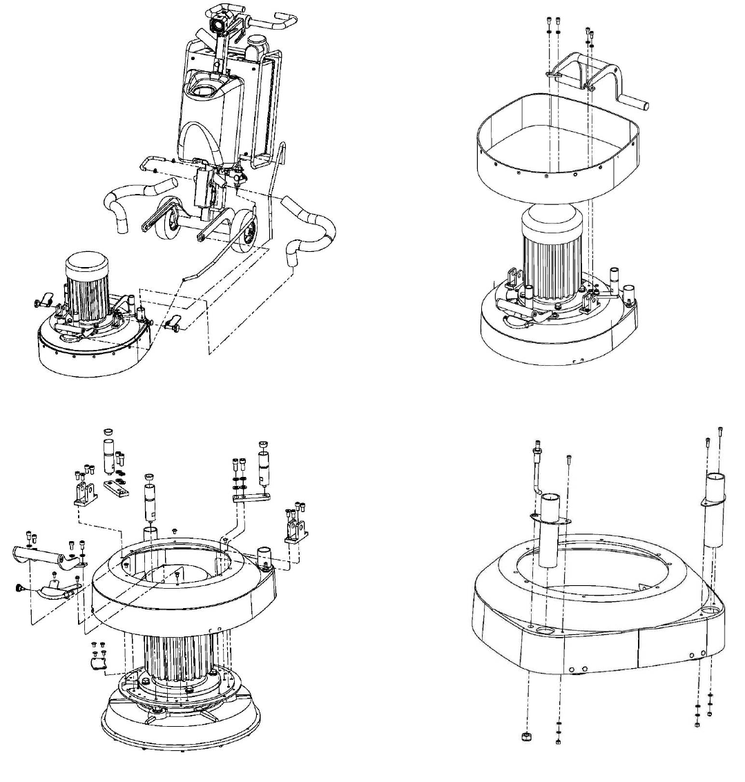
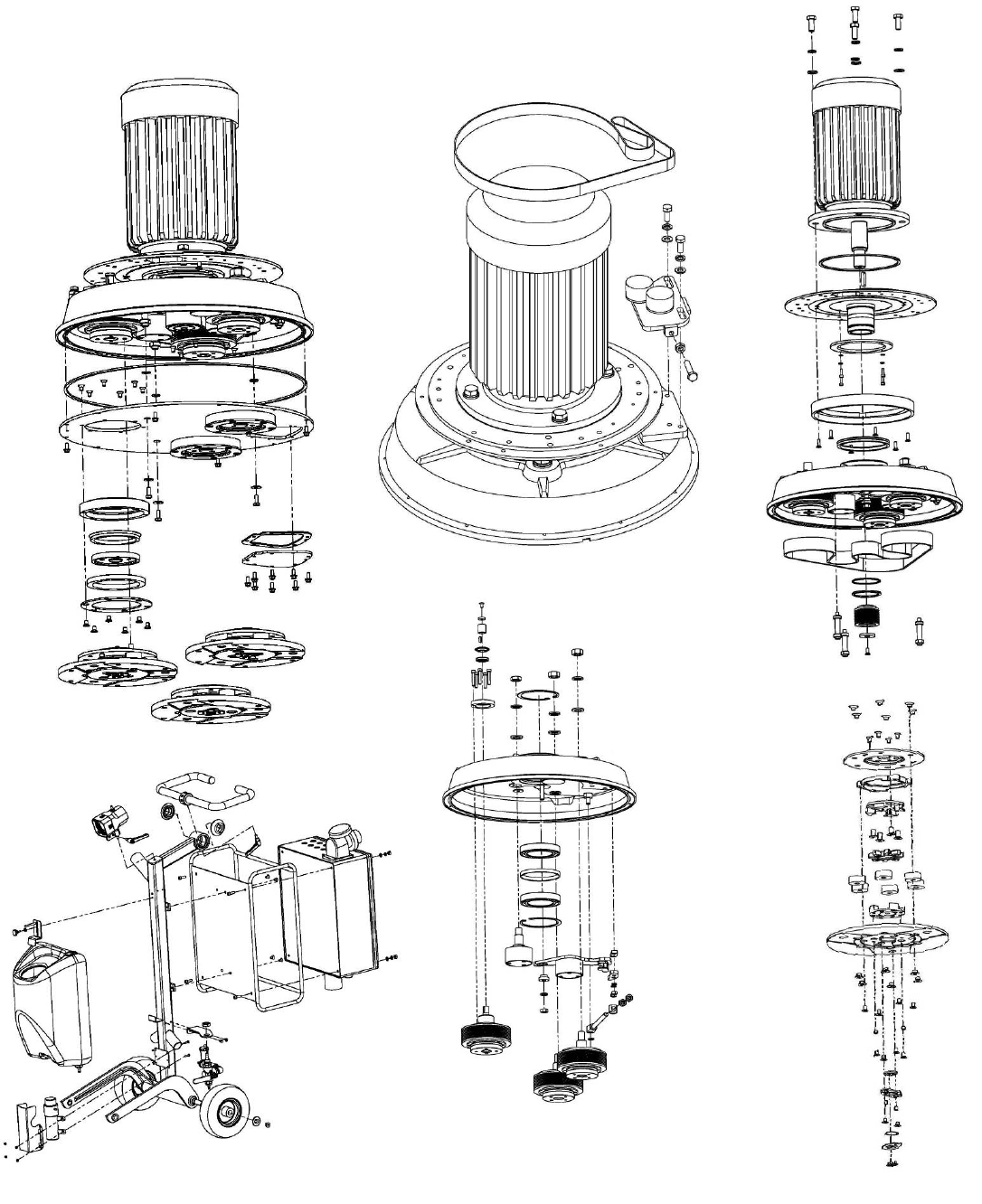
7.EXPLODEDVIEW
GENERALEXPLODEDVIEW(FIG.7.1)
MAINHEADEXPLODEDVIEW(FIG.7.2)
TOPCOVEREXPLODEDVIEW1(FIG.7.3)
TOPCOVEREXPLODEDVIEW2(FIG.7.4)
Figure 7.3
Figure 7.4
Figure 7.1 Figure 7.2
18
Superabrasive UserManual OriginalLanguageLavina®20‐S 8/2014
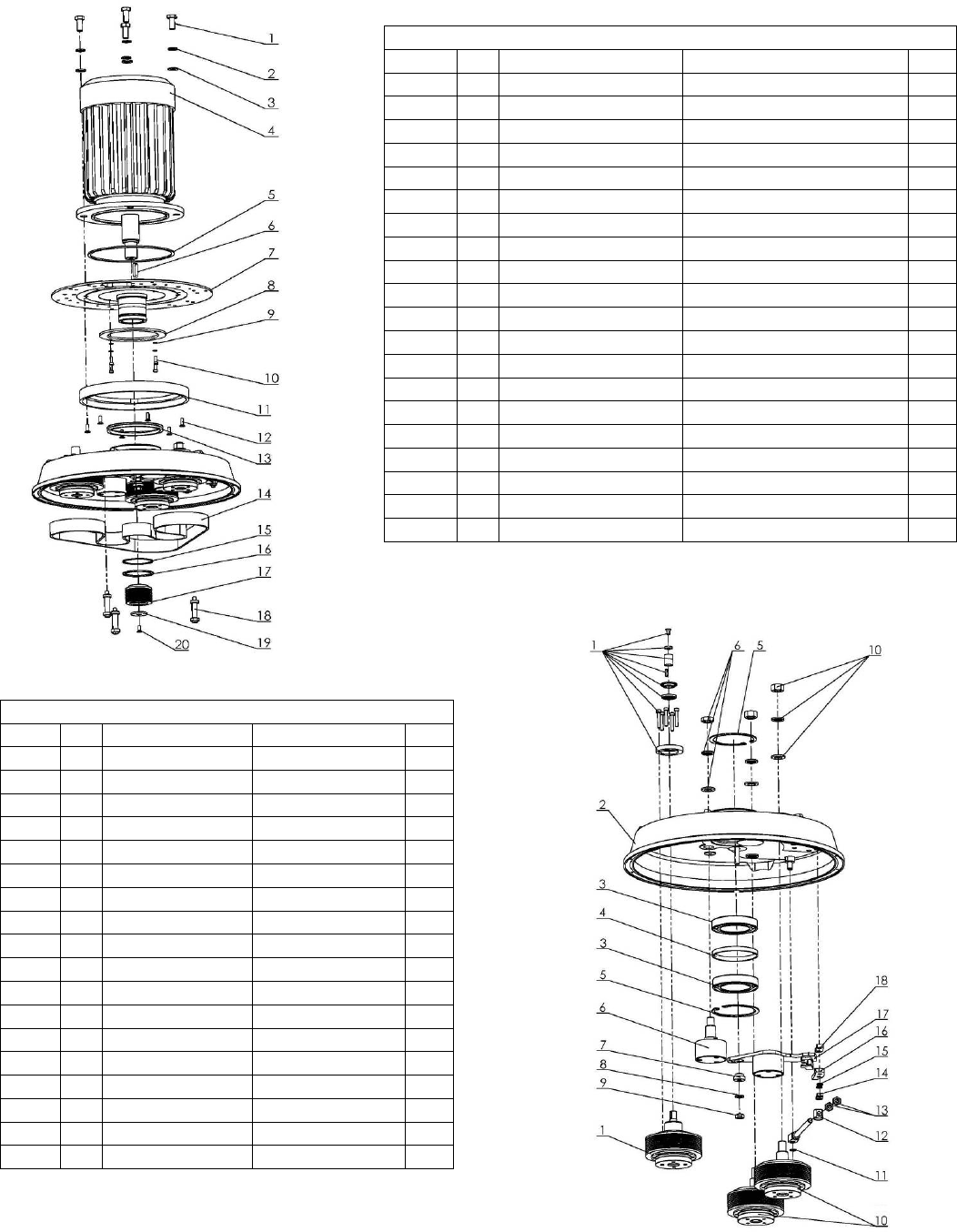
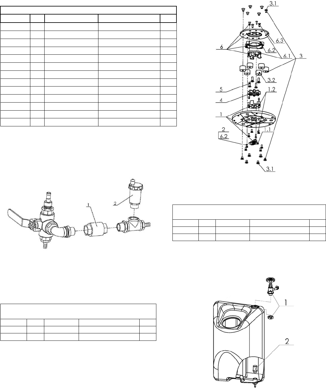
BOTTOMCOVEREXPLODEDVIEW1(FIG.7.5)
PLANETARYDRIVEEXPLODEDVIEW(FIG.7.6)
BOTTOMCOVEREXPLODEDVIEW2(FIG.7.7)
PULLEYUNITSEXPLODEDVIEW(FIG.7.8)
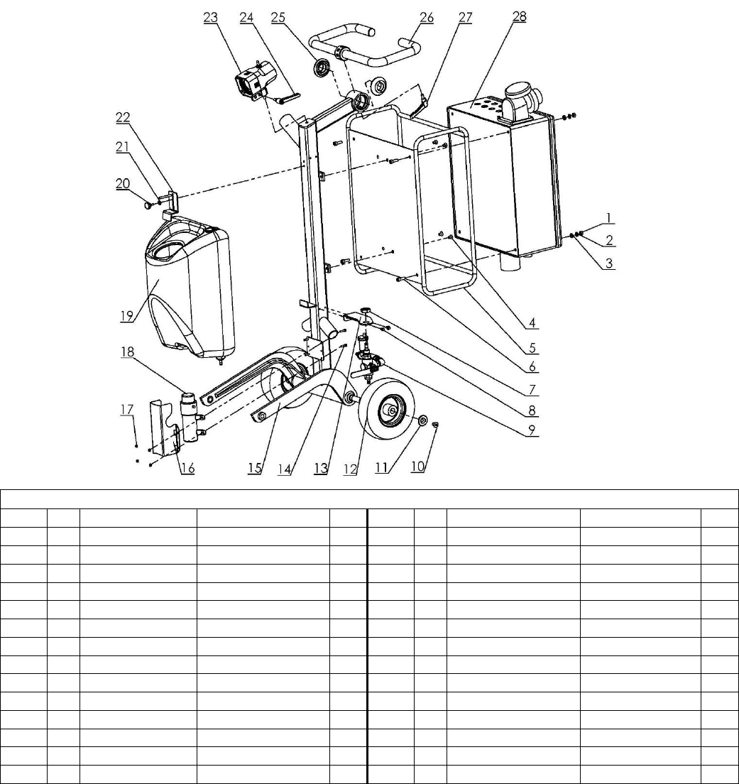
CARRIAGEEXPLODEDVIEW(FIG.7.9)
TOOLHOLDEREXPLODEDVIEW(FIG.7.10)
Figure 7.9
Figure 7.8
Figure 7.10
Figure 7.6
Figure 7.7
Figure 7.5
19
Superabrasive UserManual OriginalLanguageLavina®20‐S 8/2014
8.MAINTENANCEANDINSPECTION
CLEANING
Keepyourmachineclean.Cleaningthemachineonaregularbasiswillhelpdetectandsolvepotentialproblemsbeforetheycause
damagetothemachine.Mostimportantly,checkandcleanthetoolplateconnections,powercordandplugs,vacuumhosesand
watertank.
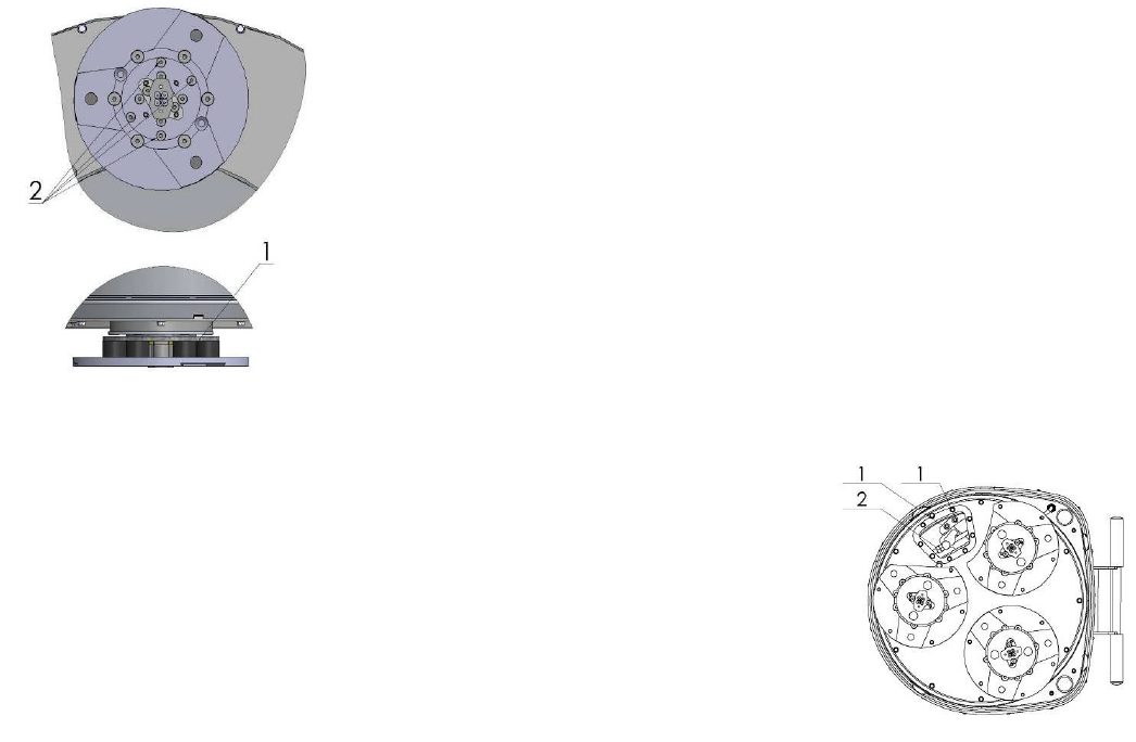
Figure 8.1
CHECKDAILY
AfteroperatingtheLavina®Smachine,theoperatorshouldconductavisualinspectionof
themachine.Anydefectshouldbesolvedimmediately.Payattentiontopowercords,
plugsandvacuumhoses,looseboltorscrews.
Toolholders:Buffersandspidersareconsumablesandmustbevisuallycheckeddailyand
replacedifneeded.Seethatflangesordiscsaremountedandlockedwellinplace.The
keylockholders(butterflies)shouldbealsochecked.
Checktherubberbuffersandfixingoftheholders.Theflangeholdingthebuffers(Fig.8.1
1)hastobefirmlyfixedtotheunit.Agapseentheremeansthatthereareloosescrews
fixingtheholder.Thescrewshavetobetightenedimmediatelyforsafeoperation.
Workingwithloosescrewsontheholdercouldalsocausebaddamagesonthemachine.
Tighteningforceofthescrewshastobe25...30N.m(18...22ft/lbs).
Itisveryimportanttoregularlycheckthescrews(Fig.8.12)thatfixthe
"Quickchange"holdertothesafetypart,sothattheholderwillnotflyawayifthebuffers
getdamaged.
“Quickchange”shouldbeclean.Thetensionoftheplanetarybeltcanbecheckeddailybymovingthemainheadandfeelingthe
resistanceofthemovingpulleys,ifthebeltslipstensionimmediately,seethechapterTroubleshooting.
CHECKANDREPLACEAFTERTHEFIRST15WORKINGHOURS
Checkthebelttensionafter15hoursworkingwiththemachine.
Thebottomcoverhasacontrolcover(Fig.8.2)thatallowsfastandeasycontrolandcorrection
ofthebelt.Itisrecommendedtocheckthetensionofthebeltafterthefirst15hoursandto
tightenifnecessary.Forthecorrecttension,seeTROUBLESHOOTING“mountingthebelt”.
Everytimeyouopenthecontrolcover,mountbackallthescrews.
CHECKEVERY200WORKINGHOURS
Every200workinghours,theoperatorshouldinspectallpartsofthemachinecarefully.Most
importantly,inspectandcleanthetoolplateconnections,powercordandplugs,vacuumhoses
andwatertank,andfilter.Also,checkthewaterflowofthepump.Checktheguard
Figure 8.2
assembly.Makecertainthewheelsarecleanandrotateproperly.Inspectthecontrolbuttons.Iftherearedefectivecontrolparts,
theyshouldbereplacedimmediately.Replacewornvacuum‐andwaterhoses.Checkthetensionofthebeltandtotightenif
necessary.Forthecorrecttension,seeTROUBLESHOOTING.
Dismountthetoolholders(SeeTroubleshooting)replaceallparts(Spider,buffers,sealercaps,“O”rings)withtheslightest
damageorconsume.
Opentheinspectioncoveronthemotorbasetochecktheplanetarydrivingbelt,bymovingthemainheadthebeltshouldnotslip
ontheplanetarypulleyanddrivethepulleys.
CHECKEVERY400WORKINGHOURS
Besidesthechecksof200workinghours,replacesealerandV‐ringslikedescribedinchapter“TROUBLESHOOTINGREPLACING
BELTANDPULLEYUNITS”.Checkifbeltsandbearingsareingoodcondition,changeifneeded.
VACUUM
Asstatedpreviously,frequentlycheckhosesandotherpartsforclogging.
WATERLEAKS
Replaceanyleakingpartsimmediatelyasthewatercoulddamageyourmachine
MECHANICALPARTS
Partssuchasthebelts,sealrings,caprings,spidersandbuffersandguardassemblyaresubjecttowearandshouldbereplacedas
needed.
ELECTRICALSYSTEM
Dustshouldnotenterthecontrolbox,asitwilldestroythecontacts.Remove(blowout)anydustpresent.
TheLavina®20N‐S200‐240Voltwillautomaticallydetectiftheconnectionisbasedonsingle(L1,L2)orthreephase(L1,L2,L3)
208‐240Volt.Theoperatordoesnothavetoswitchthemachine;onlyconnecttotwophasesorthreephases.Forconvenience,
20
Superabrasive UserManual OriginalLanguageLavina®20‐S 8/2014
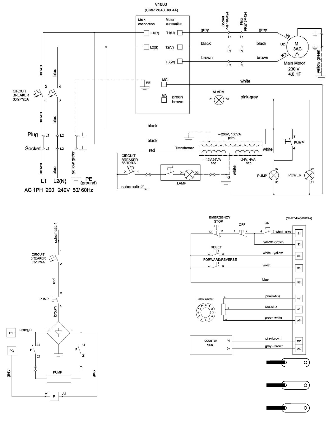
LAVINA®20‐SELECTRICALSCHEMESWITHYASKAWAINVERTER
200‐240Volt
LAVINA®20‐SELECTRICALSCHEMES
YASKAWACONNECTIONMAINCIRCUITTERMINALS
Figure 8.7
Themotorisconnectedin“Delta”
(triangle)230Volt,
reminderforthewireconnectionof
themotor.
Figure 8.4
Figure 8.6
Figure 8.5
21
Superabrasive UserManual OriginalLanguageLavina®20‐S 8/2014
Figure 9.2.7 Figure 9.2.8 Figure 9.2.9 Figure 9.2.10
Figure 9.2.11
9.TROUBLESHOOTING
INDEXOFPROBLEMSANDSOLUTIONS
9.1REPLACINGPOWERCORDANDPLUGS
Whenreplacingthepowercordorplugsalwaysusecordsandplugswithspecificationsastheoriginalones.
Neveruselowerqualityordifferenttypecordandplugs.
Inaddition,takeintoconsiderationisthedistanceoftheappliancefromtheelectricalsource.Thegreaterthedistance,the
greatertheresistanceandthelesscurrentthatwillbeavailableattheotherend,therewillbeavoltagedropandtheinverterwill
signalarmmode.Thisalsohappenifseveralmachinesareworkingonthesamelineorwhenthegeneratorisunderrated.Ingeneral
ourstandardpowercablecanbedoubledinlength,iflongerlengthsneededyouhavereplaceallthecableswithcableswithbigger
gageratedforthelengthandamperage.
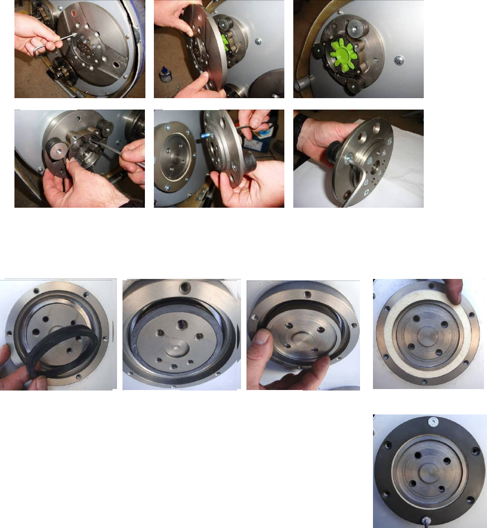
9.2DISMOUNTINGANDMOUNTINGTOOLHOLDERTOCHANGEBUFFERSANDSPIDERS,CHANGINGV‐RINGSANDFELT‐RINGS
Tocheckorreplacethebuffersandthespiders,thetoolholdershavetobedismounted.Removethecountersunkscrewsontopof
thebuffer(Fig.9.2.1).Takethediscoff(Fig.9.2.2),thespidercanberemovedorreplaced(Fig.9.2.3).BylooseningfourHexcap
bolts(Fig.9.2.4),thedisccomesloose(Fig.9.2.5)andthebufferscanbereplaced(Fig.9.2.6).Attention,bymountingusealwaysthe
“blue”threadlockingadhesive,exceptontheboltstolockthebuffers(Fig.9.2.5).Alwaysusetheoriginalbolts.
Dependingonthenumber(3,4or6)ofbuffers,theholdercanbemoreflexibleorrigid.
Whenthetoolholderisdismounted,youcanchangethesealers(V‐RingandFelt‐Ring).
TakeoutFelt‐Ring,AdaptorandV‐Ring.Beforemountingcheckonwhichsidetheadaptoris
fitting,rememberthecorrectside.MounttheV‐RingwiththesmallestlipoftheVtoinside
(Fig.9.2.7)justpushtheV‐ringsothetopisonthesamelevelasthepulleytop(Fig.9.2.8).Then
taketheadaptorinthecorrectwayandpushtheV‐Ringdownwiththeadaptor(Fig.9.2.9).The
lowestlipoftheV‐Ringshouldonlybarelytouchitsglidingsurface;alsoneverpushtheV‐Ring
downwithfingers.MountnowtheFelt‐ringontop(Fig.9.2.10).Closethesealerswiththecap
(Fig.9.2.11).
Figure 9.2.1 Figure 9.2.2 Figure 9.2.3
Figure 9.2.4 Figure 9.2.5 Figure 9.2.6
22
Superabrasive UserManual OriginalLanguageLavina®20‐S 8/2014
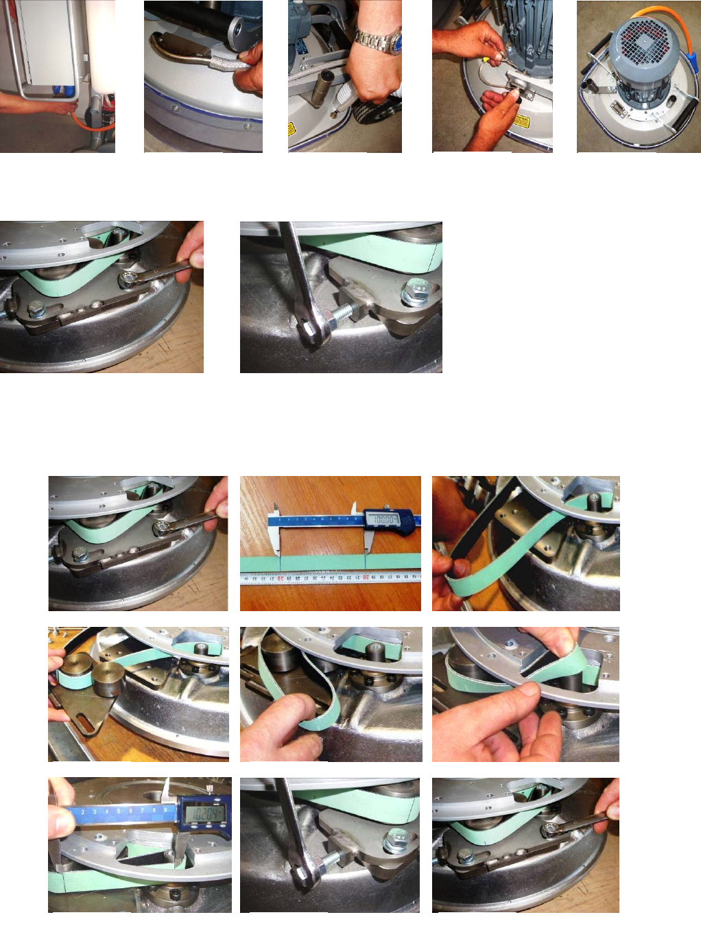
9.3 TENSIONINGANDREPLACETHEPLANETARYBELT
Ifthebeltslipsorisbrokenseparatethecarriagefrommainhead,pulloutmotorplug(Fig.9.3.1),water‐(Fig.9.3.2)(Fig.9.3.3)
andvacuumtubes.Takeoffhandles,forks,andweightholderssoyoucandismountthetopcover(Fig.9.3.4)(Fig.9.3.5)
9.4TENSIONINGUSEDPLANETARYBELT
Noticingspeedlostinplanetarymovementitispossibletotensionthebeltforplanetarymovementasdescribedin
9.5Mountingandtensioninganewplanetarybelt.
9.5MOUNTINGANDTENSIONINGANEWPLANETARYBELT
Figure 9.3.1 Figure 9.3.2 Figure 9.3.3 Figure 9.3.4 Figure 9.3.5
Figure 9.4.1 Figure 9.4.2
Figure 9.5.1 Figure 9.5.2 Figure 9.5.3
Figure 9.5.6
Figure 9.5.4 Figure 9.5.5
Figure 9.5.7 Figure 9.5.8 Figure 9.5.9
23
Superabrasive UserManual OriginalLanguageLavina®20‐S 8/2014
Completelydismountthetensioningdevice(Fig.9.5.1).Make2signsonthedismountedbelt
exactly10cmoutofeachother(beltwithouttension)(Fig.9.5.2).Thepurposeistomeasure10.2
cmonthebeltintensionwhatisatensionof2%.,amaximumof2.5%isallowed.
ATTENTION:NEVER“OVER”TENSIONTHEBELT,THEBELTWILLBEDAMAGEDANDITWILL
NEVERRECOVERITSORIGINALTENSION
Mountthebeltbackaroundtheplanetarypulley;seethatthebeltisbehindthedrivingpulley
(Fig.9.5.3).Putthebeltaroundtheleftrollerofthetensioningdevice(Fig.9.5.4).Putthe
tensioningdevicebackinplaceandpullthebeltfromtherollerontherightside(Fig.9.5.5).Put
thebeltaroundthedrivingpulley(Fig.9.5.6).Begintotensionuntilthemeasureof10cmbetweenthemarksbecomes10.2cm
(Fig.9.5.7)(Fig.9.5.8).Tightenthetensioningdevicewhileturningtheboltmovetheplanetaryheadsothebeltcanslide.(Fig.
9.5.8).Donotforgettolockthetensioningdevice(Fig.9.5.9).
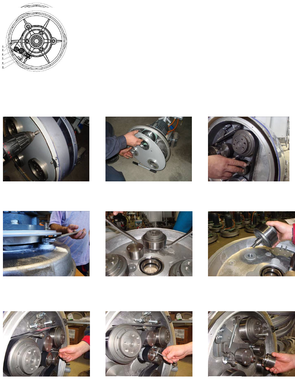
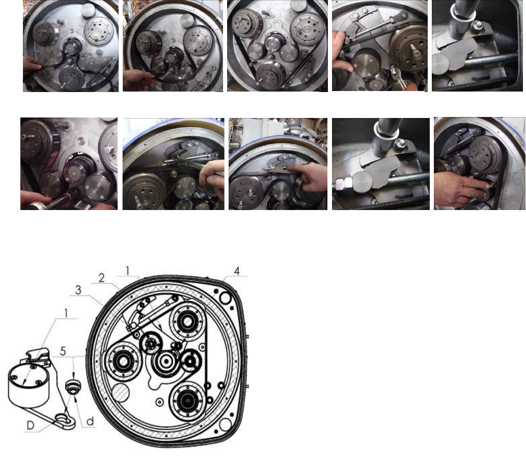
9.6REPLACINGPULLEYUNITS
Seepreviouschapterstotakeofthetoolholdersandtopcover.Unscrewthescrewsofthebottomcover(Fig.9.6.1).
Setthebottomcoverassemblyaside(Fig.9.6.2).RemovetheO‐ringstoavoidlosingthem(Fig.9.6.3).
Onlythetwoloose(non‐driving)pulleyscanberemovewithoutremovingontopthemotorbasediscandmotor.Loosethenuton
topofthepulley(Fig.9.6.4).Carefullypullouttheunitwithcrowbars,butdonotuseexcessiveforce(Fig.9.6.5)(Fig.9.6.6).
Ifallthepulleyunitshavetobereplaced,dismountmotorbasediscandmotor.Beforeremovingthebeltunscrewthecentral
pulley(soitdoesnotturnwhileunlocking)(Fig.9.6.7)(Fig.9.6.8).Pullthecentralpulleyoff(Fig.9.6.9).
Figure 9.5.10
Figure 9.5.10
Figure 9.6.1 Figure 9.6.3 Figure 9.6.2
Figure 9.6.4 Figure 9.6.6 Figure 9.6.5
Figure 9.6.7 Figure 9.6.9 Figure 9.6.8
24
Superabrasive UserManual OriginalLanguageLavina®20‐S 8/2014
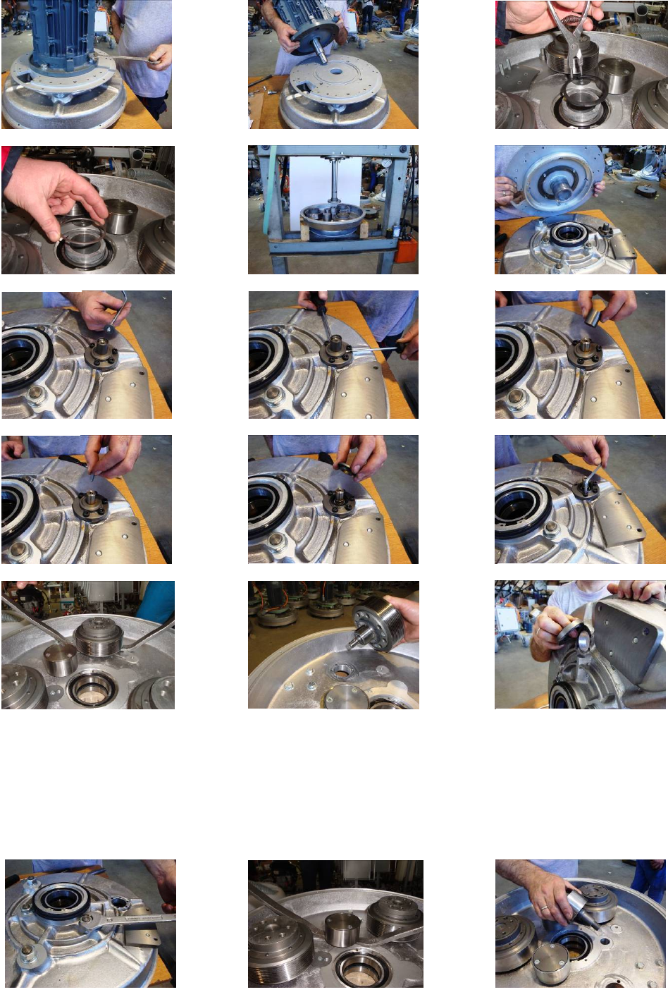
Unlockbolts(Fig.9.6.10)andtakemoreoff(Fig.9.6.11).Unlockretainingshaft/bearing(Fig.9.6.12).Takeawaythefillingring
(Fig.9.6.13).Nowthemotorbasediscisunlocked,theonlywaytodismountitistopressitoutonabearingpress(Fig.9.6.14)
(Fig.9.6.15).Dismountingthedrivingpulley:takethetopscrewouttoreleasethebushing(Fig.9.6.16),pushthebushingtogetherwith
thewasherup(Fig.9.6.17),pushwasherdownofthebushing.,takebushingout(Fig.9.6.18),pushkeyout(Fig.9.6.19),nowthewasher
releases(Fig.9.6.20),dismountsealercap(Fig.9.6.21),thepulleycanbereleasedwithtwocrowbars;donotuseexcessiveforce
(Fig.9.6.22)(Fig.9.6.23),pushthesealercaptodismount(Fig.9.6.24),bymountingbackthesealercap,securewithsealant,centerthe
holestomountthepulley.
.
Figure 9.6.10 Figure 9.6.12 Figure 9.6.11
Figure 9.6.13 Figure 9.6.15 Figure 9.6.14
Figure 9.6.16 Figure 9.6.18 Figure 9.6.17
Figure 9.6.19 Figure 9.6.21 Figure 9.6.20
Figure 9.6.22 Figure 9.6.24 Figure 9.6.23
Figure 9.6.25 Figure 9.6.27 Figure 9.6.26
25
Superabrasive UserManual OriginalLanguageLavina®20‐S 8/2014
Changethetwootherpulleysasearlierdescribedinthechapter,bestwhenthemotorbasediscisdismounttochangetheroller
unitstoo.Unlockthenutontop(Fig.9.6.25).Thepulleyscanbereleasedwithtwocrowbars;donotuseexcessiveforce(Fig.9.6.26)
(Fig.9.6.27).
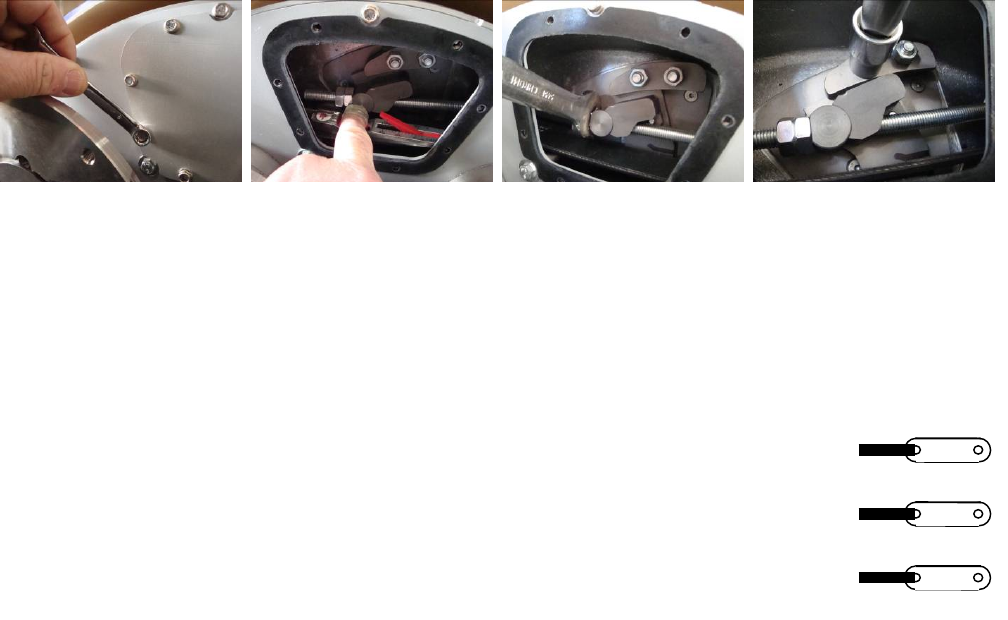
9.7MOUNTINGTHEBELT
ThemountingofthebeltisshownonFig.9.7.11.Puttingthebelt
ispossiblewhenthetensionerisinstartingposition:
‐loosenthenutspos.2
‐loosenenoughthenutspos.3(orunscrewthem).
‐unscrewthenut(pos.4)andpulloutthebush(pos.5)fromhole
Dinthetensioner(pos.1),thatwillallowthetensionertohavetheposition
inFig.9.7.11.
‐putthebeltfollowingstepsshownonFig.9.7.2;Fig.9.7.3and
Fig.9.7.4.(Itispossiblealsotoputthebeltonthe rollerunitassemblyasa
laststep.)Checkifthebeltisontherightplaceinthegroovesofeachof
thepulleyunits andonthecentralpulley.
Putbackthetensionerinapositiontheaxlebushingtofitinthe
tensionerhole(Fig.9.7.5)(Youcanpushdownthebushscrewingthenut
pos.4)
Tightenthenuts(pos.2,Fig.9.7.1)onthesectorsandunscrewhalf
rev.(Fig.9.7.5)Thiswillallowthetensionerturninminimumclearance.
Fastlightthebelt(Fig.9.7.7)inordertoachievetherightpositionandthen
tightenthenutinthecenterofthetensioner(Fig.9.7.6).Fastupthebelttakingcareofthetensioning(Fig.9.7.7).
ItisrecommendedthatthetensioningofthebeltbemeasuredwithOptikrikIIDevice(Measuringrange:500‐1400N)(Fig.9.7.8).For
anewbeltthetensioningforceis650N,andthefasteningforceis520N.
ATTENTION:NEVER“OVER”TENSIONTHEBELT,THEBELTWILLBEDAMAGEDANDITWILLNEVERRECOVERITSORIGINALTENSION
Tightenthetwonutsonthesectorsandcontranutonthetensioner(Fig.9.7.10).Putthesealringonthebottomcoverandclose
themachine(Fig.9.7.11).
Reassembleinthesamemanner.
YourLavina®Smachineisnowreadyforuse!
Figure 9.7.2 Figure 9.7.3 Figure 9.7.4
Figure 9.7.9
Fi
g
ure 9.7.1 Figure 9.7.5
Figure 9.7.6 Figure 9.7.7 Figure 9.7.8 Figure 9.7.10
Figure 9.7.11
26
Superabrasive UserManual OriginalLanguageLavina®20‐S 8/2014
9.8CHECKINGTHETENSIONOFTHEBELT
Openthecheckingcovertoreachthebeltandtensiondevice(Fig.9.8.1).Whiletensioningcheckregularlytension.Itis
recommendedthatthetensioningofthebeltbemeasuredwithOptikrikIIDevice(Measuringrange:500‐1400N)(Fig.9.8.2).
Fasteningforceis520N.
ATTENTION:
NEVER“OVER”TENSIONTHEBELT,THEBELTWILLBEDESTROYEDANDITWILLNEVERRECOVERITSORIGINALTENSIONLoosethe
contranuts(Fig.9.8.3),looselightthetwonutsofthetensiondevice(Fig.9.8.4),andadjustthetensionwiththenutseenin.When
therighttensionisreached:closethecontranutsandthetwonutsofthesupport.Reassembleinthesamemanner.
PLEASEMAKESUREYOUCHECKTHETENSIONOFTHEBELTAFTERTHEFIRST15HOURSOFOPERATION
9.9MOTORCONNECTION
Incaseofchangingthemotor,pleasecheckthecableconnectiontoyourmotor.
Lavina®20S
Themotorisconnectedin“Delta”(Triangle)230Volt,reminderforthewireconnectionofthemotor.
Figure 9.9.1
Figure 9.8.1 Figure 9.8.2 Figure 9.8.3 Figure 9.8.4
27
Superabrasive UserManual OriginalLanguageLavina®20‐S 8/2014
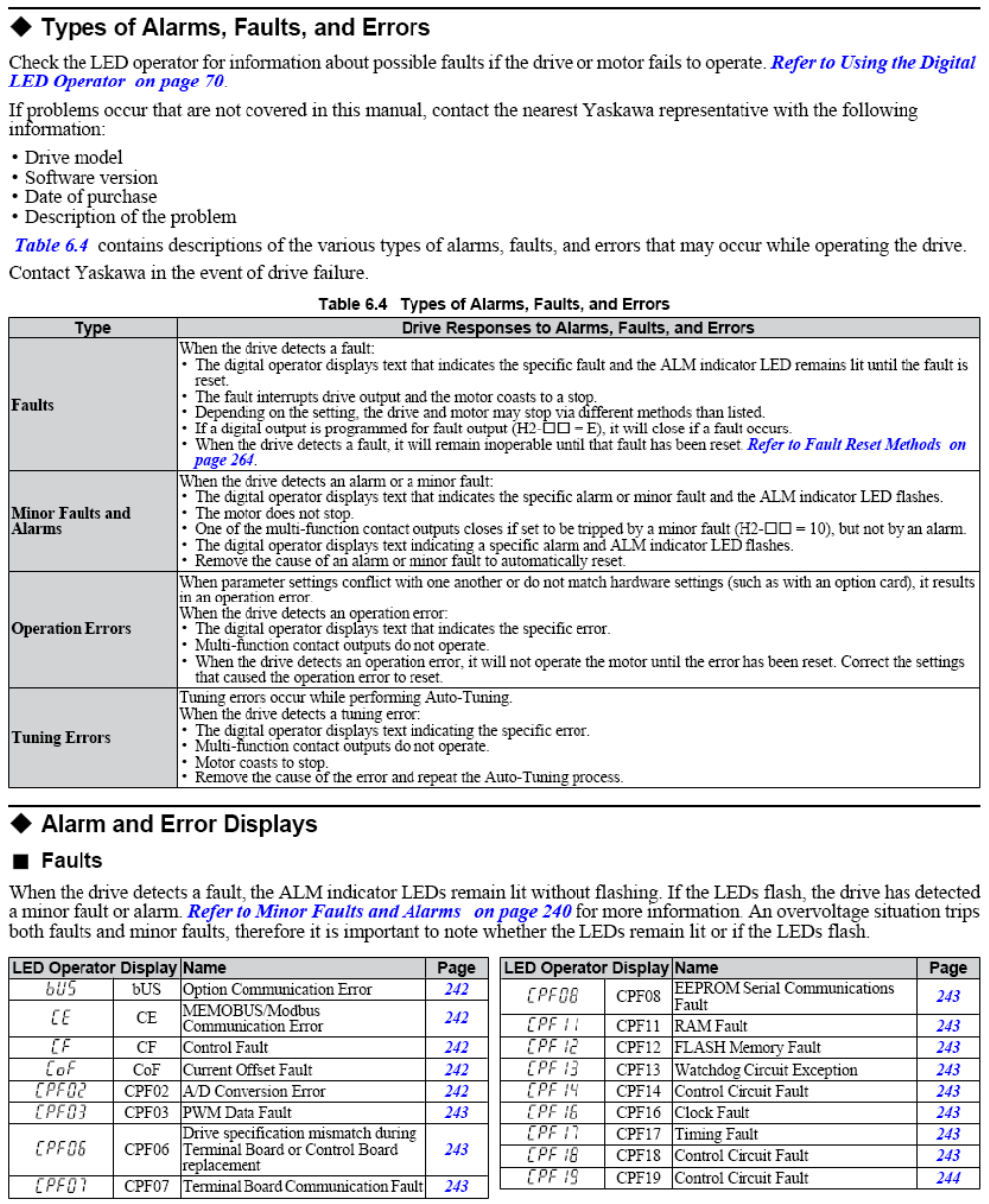
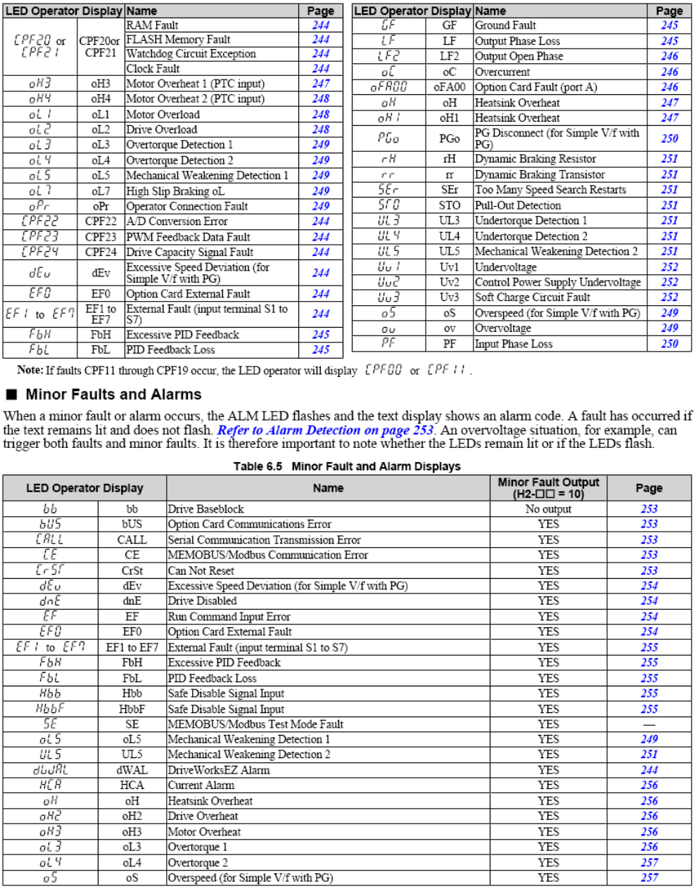
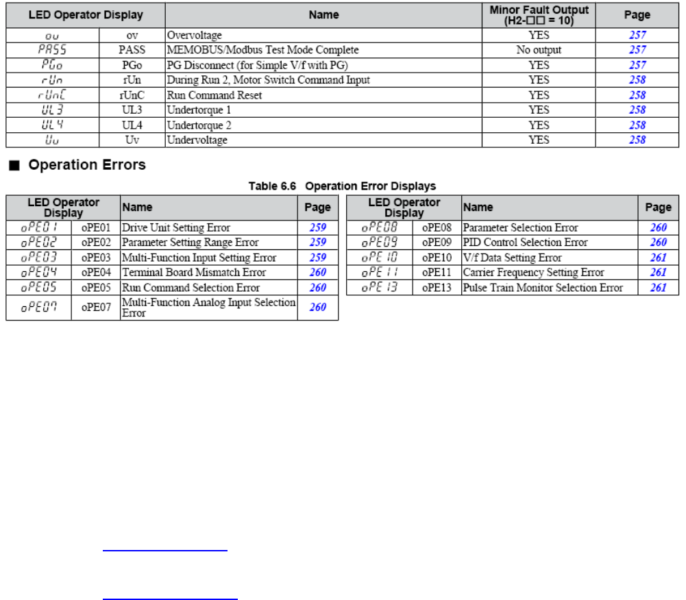
9.10FAULTDIAGNOSISINVERTERYASKAWAV1000
Pagesarereferringto
YaskawaElectricSIEPC71060618AYASKAWAACDrive–V1000TechnicalManual
28
Superabrasive UserManual OriginalLanguageLavina®20‐S 8/2014
29
Superabrasive UserManual OriginalLanguageLavina®20‐S 8/2014
.
10.DISPOSAL
Ifyourmachineaftertimeisnotusableorneedstobereplaced,sendthemachinebacktoSuperabrasiveoralocal
distributor,whereaprofessionaldisposalcomplyingwiththeenvironmentlawsanddirectivesisguaranteed.
11.MANUFACTURER’SCONTACTS
IfyouneedtocontactSuperabrasiveInc.withtechnicalsupportquestions,belowisthecontact
information.Address:9411JacksonTrailRoad,HoschtonGA30548,USA
Email:info@superabrasive.us
Tel.:7066581122
Fax:7066580357
Website:www.superabrasive.com
30
Superabrasive UserManual OriginalLanguageLavina®20‐S 8/2014
12.SPAREPARTS
ASSEMBLYANDPARTSSPECIFICATIONS
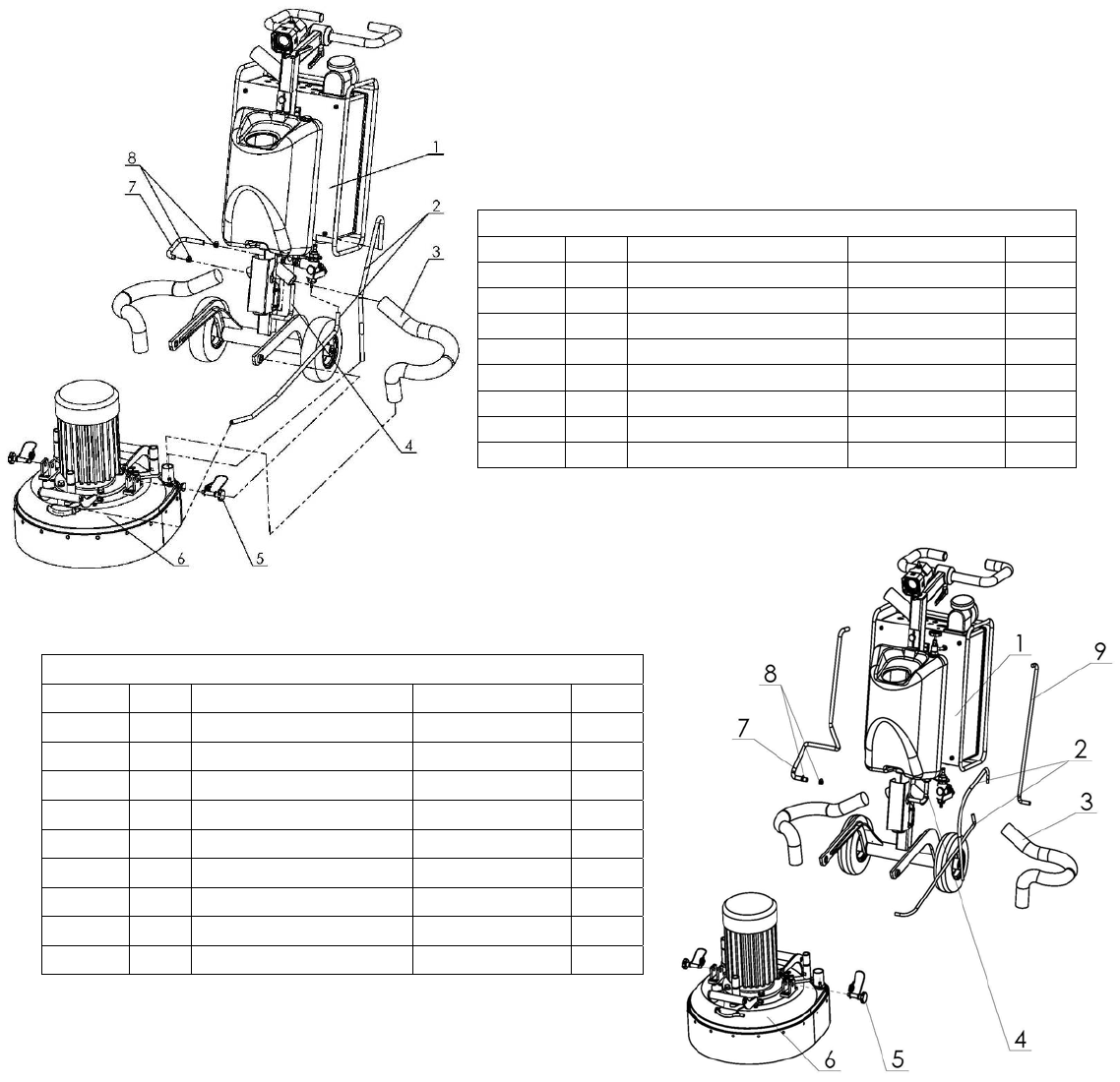
1.LAVINA®20‐SGENERALPARTS/FORMACHINESPRODUCEDBEFOREJAN.12014/
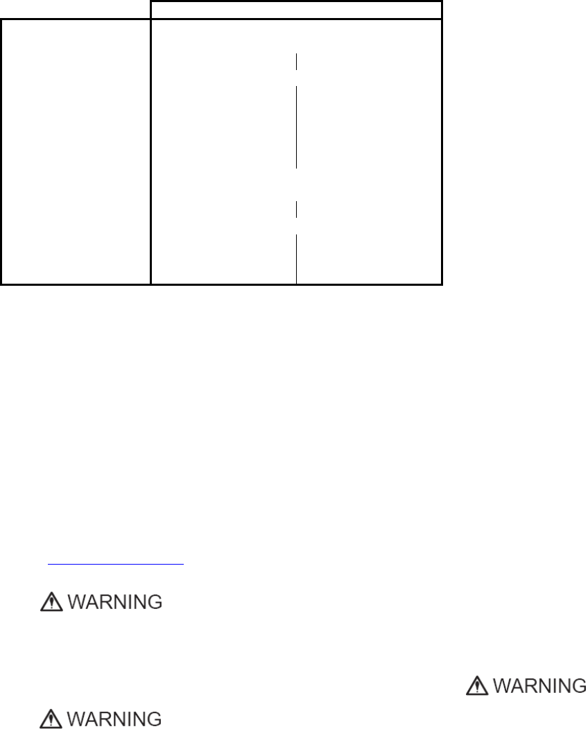
Model No. Item No. Description Pcs.
L20-S 1 L20S-20.00.00 Carriage 1
L20-S 2 MAR8.78 Tube 2
L20-S 3 D40L820 Vacuum Hose 2
L20-S 4 MAR8.20 Tube 1
L20-S 5 L25SPS-07.03.00.00 Pin Assembly 2
L20-S 6 L20S-10.00.00 Main Head 1
L20-S 7 MAR8.25 Tube 1
L20-S 8 10-16DIN3017 Clamp 2
1.LAVINA®20‐SGENERALPARTS/FORMACHINESPRODUCEDAFRTERJAN.12014/
Model No. Item No. Description Pcs.
L20-S 1 L20S-20.00.00 Carriage 1
L20-S 2 MAR8.78 Tube 2
L20-S 3 D40L820 Vacuum Hose 2
L20-S 4 MAR8.25 Tube 1
L20-S 5 L25SPS-07.03.00.00 Pin Assembly 2
L20-S 6 L20S-10.00.00 Main Head 1
L20-S 7 MAR8.85 Tube 1
L20-S 8 10-16DIN3017 Clamp 6
L20-S 9 MAR8.71 Tube 1
31
Superabrasive UserManual OriginalLanguageLavina®20‐S 8/2014
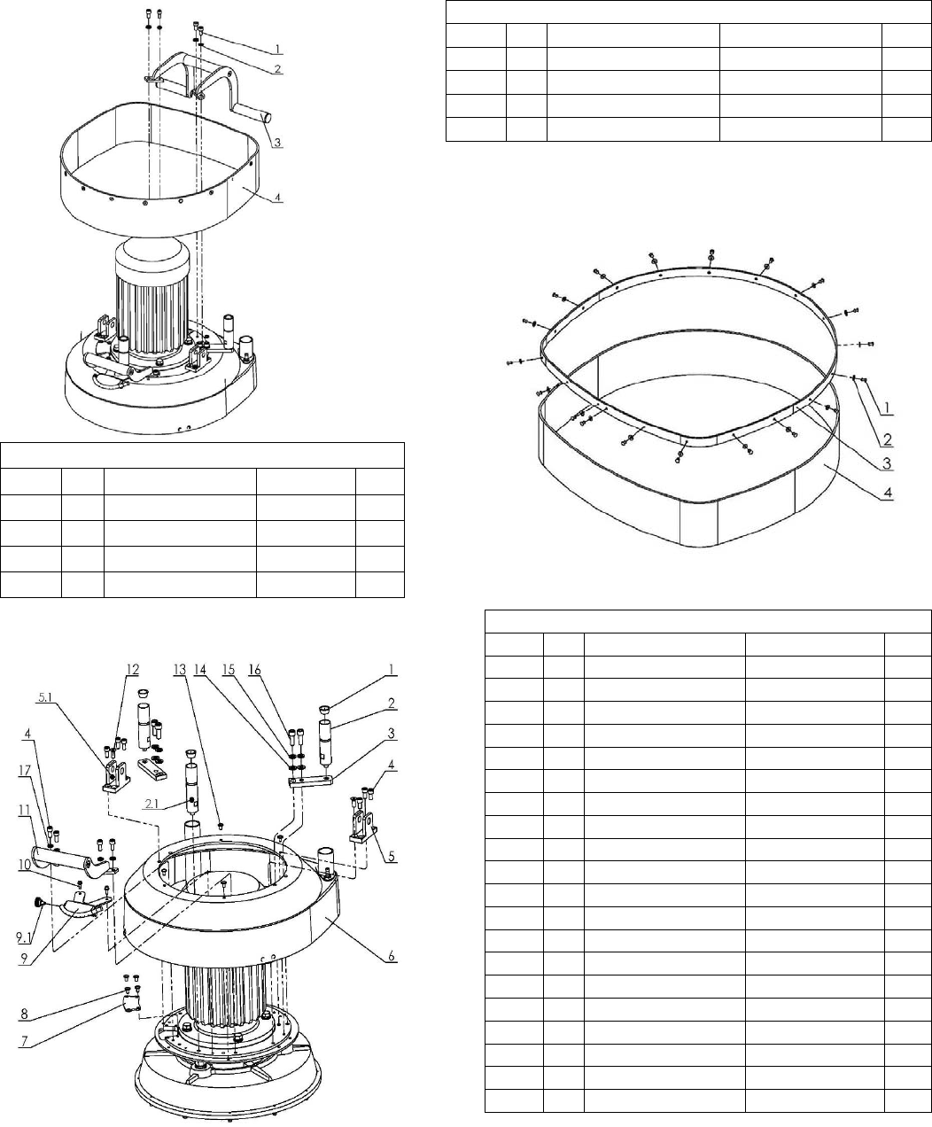
2.LAVINA®20‐STOPCOVERPARTS1
Model No. Item No. Description Pcs.
L20-S 1 M8X16DIN912 Screw 4
L20-S 2 M8DIN127B Spring Washer 4
L20-S 3 L20SPS-03.00.00.00 Machine Support 1
L20-S 4 L20SPS-05.00.00.00 Guard Assembly 1
4.LAVINA®20‐STOPCOVERPARTS2
Model No. Item No. Description Pcs.
L20-S 1 L25SPS-07.00.00.29 Rubber Buffer 3
L20-S 2 L25SPS-07.00.00.05 Weight Holder 2
L20-S 2.1 L20SPS-07.00.00.02 Front weight Holder 1
L20-S 3 L20SPS-07.00.00.01 Support 2
L20-S 4 M8X16DIN912 Screw 10
L20-S 5 L25SPS-07.00.00.02-L Left Fork 1
L20-S 5,1 L25SPS-07.00.00.02-R Right Fork 1
L20-S 6 L20S-19.00.00 Top Cover 1
L20-S 7 L20S-15.00.20 Inspection Cover 1
L20-S 8 M6X10ISO7380F Screw 4
L20-S 9 A29.10.00-01 Spray Unit 1
L20-S 9.1 H766-21 Knob Bolt
1
L20-S 10 M5X12DIN6921 Bolt 2
L20-S 11 L20SPS-08.00.00.00 Handle 1
L20-S 12 M8X20DIN7991 Screw 2
L20-S 13 M6X10ISO7380F Screw 4
L20-S 14 M10DIN125A Washer 4
L20-S 15 M10DIN127B Spring Washer 4
L20-S 16 M10X25DIN912 Screw 4
L20-S 17 M8DIN127B Spring Washer 4
3.LAVINA®20‐SGUARDPARTS
Model No. Item No. Description Pcs.
L20-S 1 D4X10DIN7337 Rivet 18
L20-S 2 M4DIN9021A Washer 18
L20-S 3 L20SPS-05.00.00.01 Ring 1
L20-S 4 L20SPS-05.00.00.02 Guard 1
32
Superabrasive UserManual OriginalLanguageLavina®20‐S 8/2014
5.LAVINA®20‐STOPCOVERPARTS3
Model No. Item No. Description Pcs.
L20-S 1 M5X16DIN84A Screw 3
L20-S 2 L25SPS-04.01.00.00 Vacuum Port 1
L20-S 4 M5DIN127B Spring Washer 3
L20-S 3 M5DIN125A Washer 3
L20-S 5 M5DIN934 Nut 3
L20-S 6 M12DIN985 Nut 1
L20-S 7 L20S-19.00.01 Top Cover 1
L20-S 8 L25GS-19.10.00 Vacuum Port 1
L20-S 9 L25GS-19.20.00 Water Fitting 1
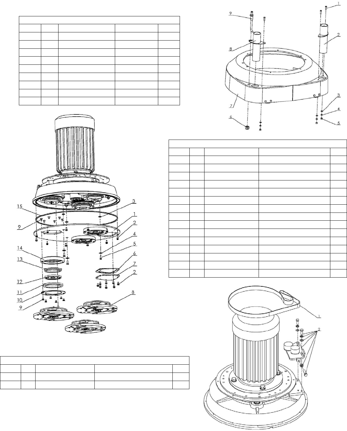
6.LAVINA®20‐SBOTTOMCOVERPARTS1
Model No. Item No. Description Pcs.
L20-S 1 L20NS-14.00.00 Bottom Cover Assembly 1
L20-S 2 M5X12DIN6921 Bolt 20
L20-S 3 D12X2 O-Ring 3
L20-S 4 M6DIN9021A Washer 3
L20-S 5 M6X16DIN933 Screw 3
L20-S 6 L20NS-14.00.05 Sealer Inspection Cover 1
L20-S 7 L20NS-14.00.04 Inspection Cover 1
L20-S 8 A31.00.00 Tool Holder A31 3
L20-S 9 M6X10DIN7991 Screw 36
L20-S 10 L25LS-14.00.03 Outer Cover 3
L20-S 11 110X90X8.5 Felt Ring 3
L20-S 12 A34.00.01 Adaptor 3
L20-S 13 TWVA00800 V-Ring Type A 3
L20-S 14 L25LS-14.00.02 Flange 3
L20-S 15 D4X2X1450 Seal 1
7.LAVINA®20‐SPLANETARYDRIVEPARTS
Model No. Item No. Description Pcs.
L20-S 1 TC-20EF1110X20X2 Endless Transmission Flat Belt 1
L20-S 2 L20S-17.00.00 Planetary Tensioning Unit 1
33
Superabrasive UserManual OriginalLanguageLavina®20‐S 8/2014
8.LAVINA®20‐SBOTTOMCOVERPARTS2
Model No. Item No. Description Pcs.
L20-S 1 M12X35DIN933 Bolt 4
L20-S 2 M12DIN127B Spring Washer 4
L20-S 3 M12DIN125A Washer 4
L20-S 4 S204 Electro Motor 1
L20-S 5 D4X2X650 Seal 1
L20-S 6 DIN6885A8X7X36 Key 1
L20-S 7 L20S-15.01.00 Base Plate 1
L20-S 8 L25P-01.03.00.09 Flange 1
L20-S 9 M5DIN7980 Spring Washer 4
L20-S 10 M5X16DIN912 Screw 4
L20-S 11 L20S-15.00.21 Planetary Pulley 1
L20-S 12 M6X20DIN7991 Screw 1
L20-S 13 TWVA01200 V-Ring Type A 1
L20-S 14 1725PK9 Endless Transmission V Belt 1
L20-S 15 L25SPS-00.00.00.23 Compensating Ring 1
L20-S 16 B65DIN471 Retaining Ring 1
L20-S 17 L20NS-00.00.08 Central Pulley 1
L20-S 18 L20NS-10.00.20 Distance Screw 3
L20-S 19 L25SPS-00.00.00.15 Front Washer 1
L20-S 20 M6X16DIN7991 Screw 1
9.LAVINA®20‐SPULLEYUNITPARTS2
Model No. Item No. Description Pcs.
L20-S 1 L20NS-16.00.00 Driving Pulley Unit 1
L20-S 2 L20NS-10.00.10 Disc 1
L20-S 3 6013 Roller Assembly 2
L20-S 4 L25SPS-00.00.00.34 Distance Ring 1
L20-S 5 A10013943 Retaining Ring 2
L20-S 6 L20P-01.05.00.00 Roller Unit Assembly 1
L20-S 7 L20NS-10.00.14 Axle Bushing 1
L20-S 8 М10DIN127B Spring Washer 1
L20-S 9 М10DIN934 Nut 1
L20-S 10 L20NS-11.00.00 Pulley Unit Assembly 2
L20-S 11 B10DIN471 Retaining Ring 1
L20-S 12 L32C-14.20.04 Nut 1
L20-S 13 M10DIN934 Nut 2
L20-S 14 М8DIN934 Nut 2
L20-S 15 М8DIN127B Spring Washer 2
L20-S 16 L20NS-10.00.11 Sector 1
L20-S 17 L20NS-12.00.00 Tensioning Support 1
L20-S 18 L20NS-10.00.12 Sector 1
34
Superabrasive UserManual OriginalLanguageLavina®20‐S 8/2014
10.LAVINA®20‐STOOLHOLDERPARTS
ModelNo.ItemNo.DescriptionPcs.
L20-S 1 A31.10.00 Quick Change Assembly 1
L20-S 1.1 A31.12.00 Keylock Set 1
L20-S 1.2 A31.10.02-K Copling 2 with screws 1
L20-S 2 M6X16DIN7991 Screw 4
L20-S 3 A25.00.10-K Buffer with two screw 6
L20-S 3.1 M8X12DIN7991 Screw 12
L20-S 3.2 A25.00.10 Buffer 6
L20-S 4 A25.00.05-02 Spider 1
L20-S 5 M8X25DIN7991-10.9 Screw 4
L20-S 6 A31.20.00 Flange 1
L20-S 6.1 A31.20.03-K Copling 1 with screws 1
L20-S 6.2 A31.20.02-K Security ring 1
L20-S 6.3 A31.20.01 Flange A31 1
11.LAVINA®20‐SWATERSUPPLYPARTS
/FORMACHINESPRODUCEDBEFOREJAN.12014/
Model No. Item No. Description Pcs.
L20-S 1 A29.21.00 Backflow Preventer 1
L20-S 2 A29.22.00 Vent Valve 1
11.LAVINA®20‐SWATERTANKPARTS
/FORMACHINESPRODUCEDAFTERJAN.12014/
Model No. Item No. Description Pcs.
L20-S 1 A29.50.00 Regulator 1
L20-S 2 1/2" Filter 1
35
Superabrasive UserManual OriginalLanguageLavina®20‐S 8/2014
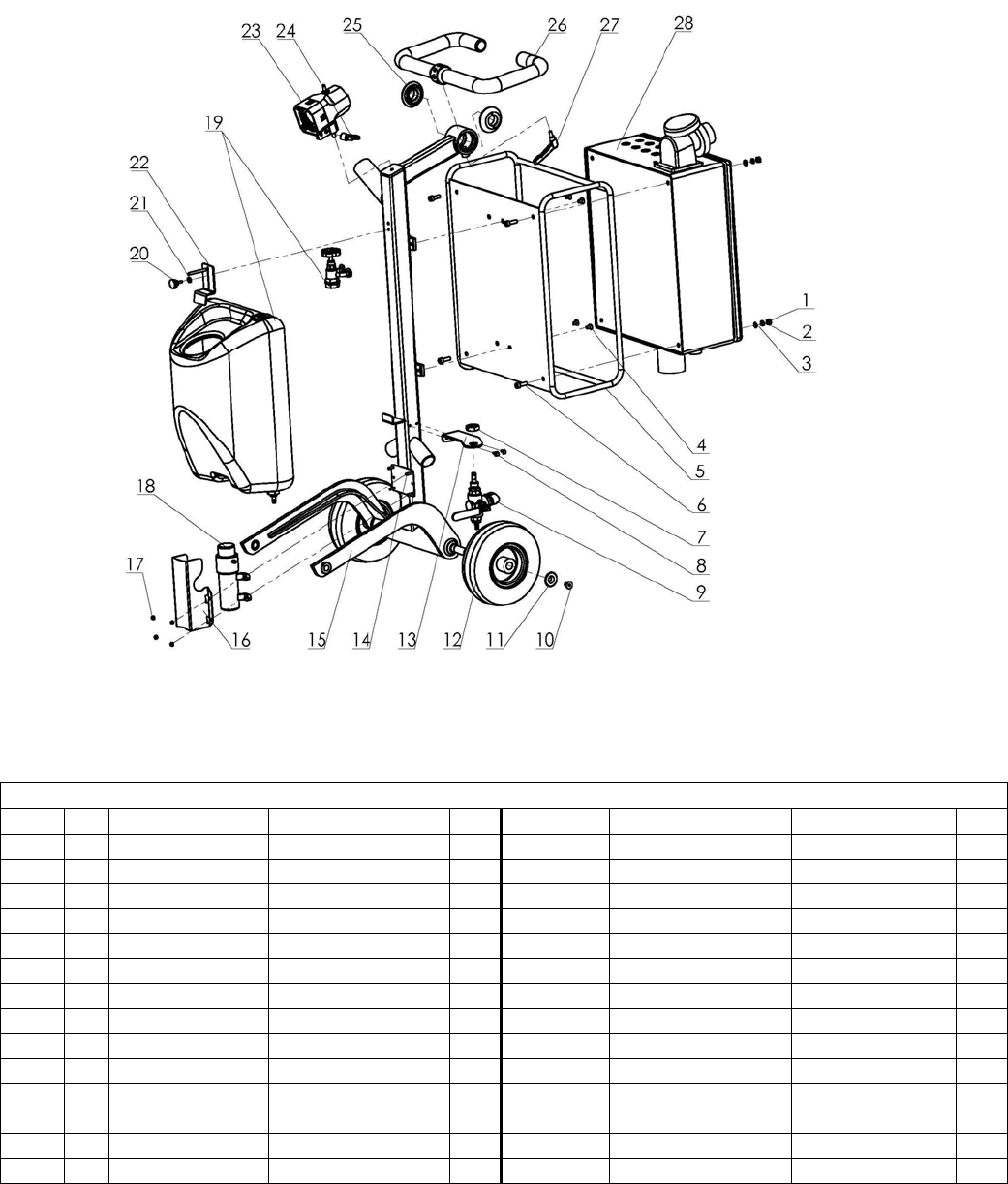
12.LAVINA®20‐SCARRIAGEPARTS/FORMACHINESPRODUCEDBEFOREJAN.12014/
Model No. Item No. Description Pcs. Model No. Item No. Description Pcs.
L20-S 1 M8DIN934 Nut 4 L20-S 15 L20S-21.00.00 Carriage 1
L20-S 2 M8DIN127B Spring Washer 4 L20-S 16 L25S-20.00.26 Guard 1
L20-S 3 M8DIN125A Washer 4 L20-S 17 M5DIN985 Nut 4
L20-S 4 M8X12DIN7991 Screw 4 L20-S 18 1040 Water Pump 1
L20-S 5 L25S-22.00.00 Guard 1 L20-S 19 A33.00.00 Tank 1
L20-S 6 M8X25DIN912 Screw 4 L20-S 20 T34391 Knob Bolt 1
L20-S 7 M20X1.5DIN439B Nut 1 L20-S 21 M5UN732 Washer 1
L20-S 8 M5X12DIN6921 Bolt 2 L20-S 22 L25P-02.00.00.01 Top Bracket 1
L20-S 9 A29.20.00 Water Flow Control Unit 1 L20-S 23 L20NS-30.30.00 Lamp Unit Incl. Cable 1
L20-S 10 M10X16DIN7991 Screw 2 L20-S 24 A58165 Swivel Bolt 1
L20-S 11 L20SPS-02.00.00.19 Cap 2 L20-S 25 L25SPS-02.00.00.18-01 Nut 2
L20-S 12 L20SPS-02.04.00.00 Wheel 2 L20-S 26 L20SPS-02.05.00.00 Handle Assembly 1
L20-S 13 A29.20.01-01 Flow Unit Base 1 L20-S 27 A58194 Swivel Bolt 1
L20-S 14 M5X20DIN933 Bolt 4 L20-S 28 L20S-30.00.00 Control Box L20-S 1
36
Superabrasive UserManual OriginalLanguageLavina®20‐S 8/2014
12.LAVINA®20‐SCARRIAGEPARTS/FORMACHINESPRODUCEDAFTERJAN.12014/
Model No. Item No. Description Pcs. Model No. Item No. Description Pcs.
L20-S 1 M8DIN934 Nut 4 L20-S 15 L20S-21.00.00 Carriage 1
L20-S 2 M8DIN127B Spring Washer 4 L20-S 16 L25S-20.00.26 Guard 1
L20-S 3 M8DIN125A Washer 4 L20-S 17 M5DIN985 Nut 4
L20-S 4 M8X12DIN7991 Screw 4 L20-S 18 1040 Water Pump 1
L20-S 5 L25S-22.00.00 Guard 1 L20-S 19 A33.10.00 Tank Assemby 1
L20-S 6 M8X25DIN912 Screw 4 L20-S 20 T34391 Knob Bolt 1
L20-S 7 M20X1.5DIN439B Nut 1 L20-S 21 M5UN732 Washer 1
L20-S 8 M5X12DIN6921 Bolt 2 L20-S 22 L25P-02.00.00.01 Top Bracket 1
L20-S 9 A29.40.00 Water Flow Control Unit 1 L20-S 23 L20NS-30.30.00 Lamp Unit Incl. Cable 1
L20-S 10 M10X16DIN7991 Screw 2 L20-S 24 A58165 Swivel Bolt 1
L20-S 11 L20SPS-02.00.00.19 Cap 2 L20-S 25 L25SPS-02.00.00.18-01 Nut 2
L20-S 12 L20SPS-02.04.00.00 Wheel 2 L20-S 26 L20SPS-02.05.00.00 Handle Assembly 1
L20-S 13 A29.20.01-01 Flow Unit Base 1 L20-S 27 A58194 Swivel Bolt 1
L20-S 14 M5X20DIN933 Bolt 4 L20-S 28 L20S-30.00.00 Control Box L20-S 1
37
Superabrasive UserManual OriginalLanguageLavina®20‐S 8/2014
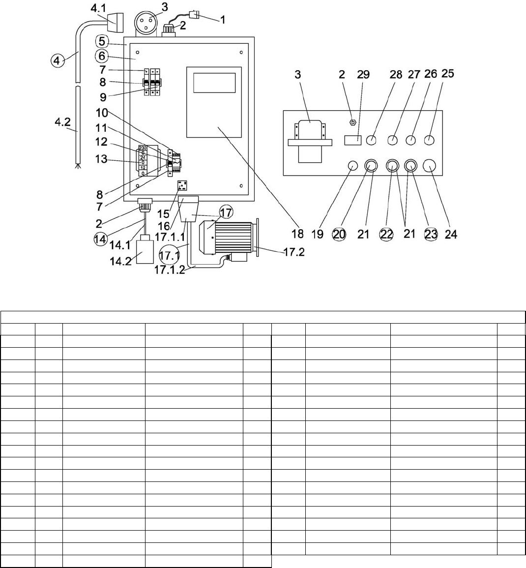
13.LAVINA®20‐SCONTROLBOXPARTS200‐240VOLT
13.LAVINA®20‐SCONTROLBOXPARTS200‐240VOLT
L20-S No. Item No. Description Pcs. No. Item No. Description Pcs.
L20-S 1 L20NS-30.30.00 Lamp Unit Incl. Cable 1 16 L20S-30.10.03 Socket 1
L20-S 2 L20NS-30.10.01 Cable Gland 2 17 L20S-30.20.00 Electro Motor Assembly 1
L20-S 3 L20S-30.10.02 Plug on Control Board 1 17.1 L20S-30.20.10 Plug with Cable 1
L20-S 4 L20S-30.02.00 Cable with Connector 1 17.1.1 L20S -30.20.11 Plug 1
L20-S 4.1 L20S -30.02.01 Connector 1 17.1.2 L20S-30.20.12 Cable for Electro Motor 1
L20-S 4.2 L20S-30.02.02 Cable 1 17.2 S204 Electro Motor 1
L20-S 5 L20S-30.10.00 Metal Box 1 18 L20S-30.11.09 Inverter Yaskawa (V1000) 1
L20-S 6 L20S-30.11.00 Metal Box Plate 1 19 L20NS-30.10.04 Potentiometer 1
L20-S 7 L20NS-30.11.01 Circuit Breaker 2 20 L20NS-30.10.05 Reset Button 1
L20-S 8 L20NS-30.11.02 Rail 2 21 L20NS-30.10.06 Cap 3
L20-S 9 L20S-30.11.03 Circuit Breaker 1 22 L20NS-30.10.07 Off Button 1
L20-S 10 L20NS-30.11.04 Rail Base 1 23 L20NS-30.10.08 On Button 1
L20-S 11 L20NS-30.11.05 Rail 1 24 L20NS-30.10.10 Emergency Stop Button 1
L20-S 12 L20NS-30.11.06 Rail Bracket 1 25 L20NS-30.10.11 Switch Button F/R 1
L20-S 13 L20NS-30.11.07 Transformer 1 26 L20NS-30.10.12 Green LED Power 1
L20-S 14 L20NS-30.40.00 Water Pump with Cable 1 27 L20NS-30.10.13 Water Pump Button 1
L20-S 14.1 L20NS-30.40.01 Cable for Water Pump 1 28 L20NS-30.10.14 Blue Led Alarm 1
L20-S 14.2 1040 Water Pump 1 29 L20NS-30.10.15 Revolution counter 1
L20-S 15 L20NS-30.11.08 Rectifier 1
