2014 L30G S USA Version 8 LAVINA 30G
2016-06-14
: Guide 2014 Lavina 30G-S Usa Version 8 2014 LAVINA 30G-S USA version 8 SUNBELT LAVINA S SERIES 2016 Lavina manuals Niagara-Library
Open the PDF directly: View PDF ![]() .
.
Page Count: 36
Superabrasive Owner’sManual–LAVINA®30G‐S8/2014
1
LAVINA® 30G-S User Manual
Tech Support Line: 800-987-8403 | www.superabrasive.com | info@superabrasive.us
SuperabrasiveOwner’sManual–LAVINA®30G‐S8/2014
2
SuperabrasiveOwner’sManual–LAVINA®30G‐S8/2014
3
WARRANTY AND RETURNS
WARRANTY POLICY FOR LAVINA® S MACHINES
A warranty card must be submitted to Superabrasive within 30 days of purchase in order for the foregoing warranty to
apply.
You can either mail a hard copy of the warranty card or submit it electronically - see page 2.
Superabrasive warrants, from the time of delivery and receipt by the original customer, new and unused products
sold by
Superabrasive or Superabrasive-appointed distributors or dealers. Goods shall be free from defects in
materials and
workmanship. Superabrasive or a Superabrasive-appointed repair facility shall either replace or
repair any defects in the
Goods resulting from faulty design, materials, or workmanship. Products repaired or
replaced during the warranty period
shall be covered by the foregoing warranty for the remainder of the original
warranty period, or ninety (90) days from date
of the repair or shipment of the replacement, whichever is longer.
Spare parts for repair will be either new or equivalent to
new.
Warranty period shall be 2 years from the time of delivery and receipt by the original customer, or 600 operating
hours on
the machine - whichever occurs first. Superabrasive will cover the shipping charges for the transportation
of the machine to
Superabrasive (or an approved repair facility) and back to the customer (within the contiguous 48
United States) in the event
that the damage occurs and is reported within the first 90 days or 200 operating hours -
whichever occurs first. Shipping
charges, if covered by Superabrasive, must be agreed upon in advance and
approved by Superabrasive. Thereafter, the
customer will have to cover the shipping charges to Superabrasive and
back. Superabrasive will not warranty Goods after a
period of 2 years from the time of delivery and receipt by the
original customer, or 600 operating hours on the machine -
whichever occurs first.
Superabrasive shall not be liable for any defects that are caused by circumstances that occur after the Goods
have been
delivered and whilst the Goods are in the possession of the purchaser. Furthermore, the warranty
does not include normal
wear and tear or deterioration. Wear parts are not warranted. Superabrasive is not liable
for defects arising out of use of
non-OEM parts.
The Warranty is void if the purchaser has not followed the maintenance plan stipulated by the machine’s manual
and
warranty card. The warranty is void if the purchaser repairs said Goods himself, or if repairs are conducted by a
repair facility
that is not approved by Superabrasive. Superabrasive’s liability does not cover defects which are
caused by faulty
maintenance, incorrect operation, faulty repair by the purchaser, or by alterations conducted
without Superabrasive’s prior
written consent. The same applies to any alterations of the Goods or services
performed by another party other than
Superabrasive, a Superabrasive-appointed distributor, or a Superabrasive-
approved repair facility. The warranty is not
applicable on a defect that arises due to tools or parts that are not
original to Superabrasive. Replaced defective parts shall
be placed at Superabrasive’s disposal and shall become
property of Superabrasive. If such defective parts are replaced
within the warranty period, the shipping charges will be covered by Superabrasive. In warranty complaint cases,
when no
defects are found for which Superabrasive is liable, Superabrasive shall be entitled to compensation for
the labor, material
cost, and shipping charges, incurred by Superabrasive as as a result of the complaint.
The warranty herein is non-transferable, and only applies to the original owner or purchaser of the machine.
RETURN POLICY FOR LAVINA® S MACHINES
The Lavina® S machines may be returned, subject to the following terms:
In no case, a machine is to be returned to Superabrasive Inc. for credit or repair without prior authorization.
Please contact
Superabrasive Inc. or your local distributor for an authorization and issuance of a return
authorization number. This number
along with the serial number of the machine must be included on all packages
and correspondence. Machines returned
without prior authorization will remain property of the sender and
Superabrasive Inc. will not be responsible for them. No
machines will be credited after 90 days from the date of
invoice.
All returns must be shipped freight prepaid. Returned machines may be exchanged for other equipment or parts of
equal
dollar value. If machines are not exchanged, they are subject to a fifteen percent (15%) restocking fee.
Superabrasive Owner’sManual–LAVINA®30G‐S8/2014
4
WARRANTYANDRETURNS 3
1.GENERALINFORMATION
Preface5
Manufacturer 5
GeneralDescription 5
MachineCharacteristics 5
LAVINA®30G‐SMainDesign 5
EnvironmentalConditions 6
VacuumConnection 6
TechnicalData 6
Vibrations6
SonorousEmissions 6
LabelData6
Customerservice 6
2.SAFETYINSTRUCTIONS
RecommendedUse 6
ProhibitedUse 6
PreparationforWork 7
ProtectionDevices 7
ArrestFunctions 7
SafeUse
PropaneSafety 7
FireSafety7
Emission7
HazardCommunication 7
LocalAgenciesandRegulations 8
ResidualRisks 8
BeforeYouBegin 8
OperatingtheMachine 8
AfterWorkiscompleted 8
TheWorkArea 8
PersonalProtectiveEquipment(PPE) 8
Testing9
Operator9
PropaneCylinders 9
RefuelingCylinders 9
StorageCylinders 10
TransportingCylinders 10
3.HANDLINGANDTRANSPORTATION
Adjustingthehandle 10
Liftthemachinefromwork
totoolmountingposition 11
Lifting11
Storage11
MountingofGuardAssembly 12
4.OPERATION
PreliminaryControls 12
WaterFlowControlUnit 12
AdjustingandMountingTools 12
FrameBlocking(U‐Joint) 12
Alarm12
ControlBoard 13
StartingtheMachine 13
OperatingMachine 13
StoppingMachine 13
5.TOOLSANDACCESSORIES
Weights 14
ToolHolderKey 14
FoamPlate14
SecurityPlateforQuickchangePads 14
6.POPULARTOOLSANDAPPLICATIONS
Tools 15
7.EXPLODEDVIEW
GeneralExplodedView 16
TopCoverExplodedView1 16
PlanetaryDriveExplodedView 16
TopCoverExplodedView2 16
BottomCoverExplodedView1 17
BottomCoverExplodedView2 17
CarriageExplodedView 17
ToolHolderExplodedView 17
8.MAINTENANCEANDINSPECTION
Remark18
Mechanicalparts 18
Cleaning18
CheckHourly 18
CheckDaily 18
Checkandreplaceafterthefirst8workinghours 18
Checkandreplaceafterthefirst15workinghours 18
Checkandreplaceevery50WorkingHours 19
Checkandreplaceevery200WorkingHours 19
Checkandreplaceevery400WorkingHours 19
Vacuum19
WaterLeaks 19
MechanicalParts 19
ElectricalSystem 19
9.TROUBLESHOOTING
9.1Engine20
9.2Checkingandchangingtheoil 20
9.3Separatingtheheadfromthecarriage 20
9.4Dismounting/mountingoftheengine 21
9.5Replacingtheclutch 22
9.6DismountingandMountingToolHoldersto
changeBuffersandSpiders,ChangingV‐Rings
andFelt‐Rings 22
9.7TensioningandReplacingthePlanetaryBelt 23
9.8TensioningUsedPlanetaryBelt 23
9.9MountingandTensioninganewPlanetaryBelt 24
9.10CheckingtheTensioningoftheBelt 24
9.11ReplacingthePulleyUnits 25
9.12Mountingthebelt 26
10.DISPOSAL 27
11.MANUFACTURER’SCONTACTS 27
12.SPAREPARTS
ASSEMBLYANDPARTSSPECIFICATIONS 28
1Generalparts/formachinesproducedbeforeJan.12014/28
1Generalparts/formachinesproducedafterJan.12014/28
.2TopCover1parts/formachinesproducedbeforeJan.12014/29
2TopCover1parts/formachinesproducedafterJan.12014/29
3EngineBaseParts 30
4TopCover2parts 30
5PlanetaryDriveParts 31
5a.PulleyUnitAssembly 31
5b.DrivingPulleyUnit 31
6WaterSupplyparts/formachinsproducedbeforeJan.12014/32
6WaterSupplyparts/formachinesproducedafterJan.12014/32
7BottomCover1Parts 32
8ToolHolderParts 32
9BottomCover2Parts 33
10ControlBoardParts 33
11Carriageparts/formachinesproducedbeforeJan.12014/34
11Carriageparts/formachinsproducedafterJan.12014/35
12Engineparts 36
SuperabrasiveOwner’sManual–LAVINA®30G‐S8/2014
5
1.GENERALINFORMATION
Thisowner’smanualisintendedfortheoperatoroftheLavina®Smachine,theservicingtechnicianaswellasforanyone
involved
withoperatingorservicingthemachine.Werecommendthatyoureadtheinstructionsverycarefullyandfollowthem
strictly.
Themanualincludesinformationaboutassembling,using,handling,adjustingandmaintainingyourLavina®Sfloorgrinding
and
polishing
machine.
MANUFACTURER
Superabrasivewasfounded24yearsago,in1987,asamanufacturerofhighqualitydiamondtoolsforthestoneand
concrete
industry.Today,Superabrasiveisoneoftheworld’sleadingcompaniesintheproductionofdiamondtoolsand
floor
grinding
machinery.AtSuperabrasive,westrivetodelivertheverybestsolutionstoourcustomers,andenablethem
towork
moreefficiently
.
GENERALDESCRIPTION
TheLavina®Smachineisintendedforgrinding,polishingandbuffingconcrete,marble,granite,limestoneandterrazzosurfaceswith
diamondtools.
TheLavina®Smachineisathree‐discmachine,whichcanbeuseddryaswellaswet.
Forbestresults,useonlytoolsmanufacturedorrecommendedbySuperabrasiveanditsdistributors.Additionally,themachinecould
beusedforgrindingwoodfloorsurfaces.
TheLavina®Smachineismanufacturedandfittedfortheabove‐
mentionedapplicationsonly!Everyotherusemaypossessriskstothepersonsinvolved.
MACHINECHARACTERISTICS
TheLavina®Smachineismadeoftwomaincomponentsections:
LAVINA®30G‐SMAINDESIGN
Thetwomaincomponentsarethecarriageandmain
head.
Thehandleontheframeisadjustableinheightandallowstheoperatortoworkinacorrect
andsafeposture.
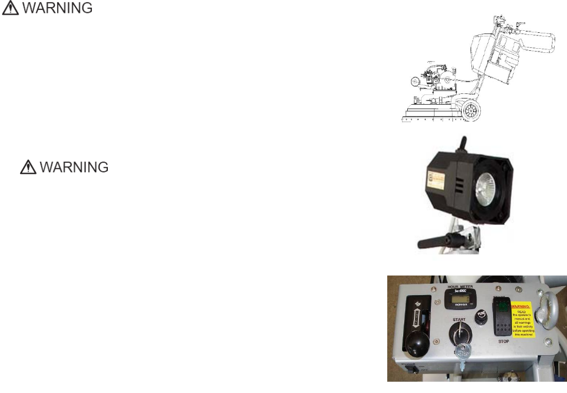
Thehalogenspotlight(Fig.1.2)enablestheoperatortoworkindarker
areas.
Existinglightingsystemdoesnotreplaceadequateoverhead
lighting.
Aframe(U‐jointtechnology)ontopofthemotorbaseisprovidingthemainhead
a
possibletomovetoallsidesanditgivesmoregrinding
capacity.
Thepropanetankisplacedonatankholderonthebacksideofthe
frame.
Thecontrolpanel(fig.1.3)ispositionedontopoftheframeandcontains
switching
devices,whichensuretheproperfunctioningoftheengine,LPGsupplyturning
on/off
oftheelectromagnetic
connector/clutch.
Thewatertankisontheoppositesideoftheframe,sothattheweightof
the
water
doesnotaffecttheoperationofthemachine.Theframeweight,on
the
otherhand,
isfullyabsorbedbythedrivingwheels.Anelectricpumpsprays
the
waterthrougha
frontsprayeror
internal
TheEngineKawasakiFS481Vwithelectricclutchismountedonthebaseplate
and
itisdrivingthethreeheadswithabelt
system.
Theplanetarymotionderivesfromthemainengine,drivenbyasecondflat
belt,
Theself‐levelingGuardisdesignedtohavecontactwiththesurface.Anytime,
no
mattertheheightofthetool
used.
“Quickchange”toolholderisdesignedtoholdthetoolswith
“Quickchange”connection.
The“Foam”toolholderisdesignedtoholdtoolswithVelcroconnection.Itismountedoneachofthethreegrindingheads
with
akeylock(butterfly).TheVelcromakeschangingoftoolsfastand
easy
Figure 1.1
Figure 1.3
Figure 1.2

Superabrasive Owner’sManual–LAVINA®30G‐S8/2014
6
ENVIRONMENTALCONDITIONS
ThetemperaturerangeforoperatingtheLavina®Smachineoutdoorsisbetween41°Fand86°For5°Cand30°C.Neveruse
the
Lavina®Smachineduringrainorsnowwhenworkingoutdoors.Whenworkingindoors,alwaysoperatethemachinein
well‐
ventilated
areas.
VACUUMCONNECTION
Aconnectionforavacuumdustextractorislocatedonthecarriage.TheLavina®Smachinedoesnotincludeavacuumdust
extractor.Thecustomermustpurchasethevacuumdustextractorseparately.ThehoseofthevacuumextractormustbeØ50.8
mmandcanbeglidedoverthepipe.Thevacuumdustextractormustbeadaptedforfloorgrindersandhaveaminimumair
displacementof320m3/hwithanegativevacuumof21kPa.
TECHNICALDATA
VIBRATIONS
ThevibrationsofthemachinearewithinthelimitsofdirectivesandharmonizedstandardsfromtheEuropeanUnionwhen
the
Lavina®Sisoperatedwiththerecommendedtoolsandinnormal
conditions
.
SONOROUS
EMISSIONS
ThesonorousemissionsarewithinthelimitsofdirectivesandharmonizedstandardsfromtheEuropeanUnionwhenthe
Lavina®
Sisoperatedwiththerecommendedtoolsandinnormalconditions.However,aspreviouslystated,theoperator
mustwear
earprotectors.
LABEL
DATA
ThedataonthelabelprovidesthecorrectVoltageandkW(neededforoperational
purposes);
Weight(neededfortransportationpurposes);productionyearandserialnumber(neededformaintenance
purposes).
CUSTOMER
SERVICE
ForcustomerassistanceandtechnicalsupportcallyourlocaldistributororcallSuperabrasiveInc.
at
1‐800‐987‐8403orvisitusat:www.superabrasive.com,whereyoucandownloadacopyofthis
manual
.
2. SAFETY INSTRUCTIONS
RECOMMENDED
USE
TheLAVINA®25G‐Smachineisdesignedandmanufactured
to
grindandpolishconcrete,terrazzoandnaturalstonefloors.
It
can
beusedforrenovationsaswellasforpolishing.
The
machineis
designedfordryorwetuse.Whenusingitdry,
use
avacuumof
appropriatesize.Formoreinformation,
please
refertothe
chapteronhandlingthevacuum
connection.
PROHIBITEDUSE
ThemachineMUSTNOTbe
used:
Forapplicationsdifferentfromtheonesstatedin
the
GeneralDescription
chapter.
Inenvironments
which:
- Possessrisksof
explosion
-Possesshighconcentrationofpowdersor
oil
substancesinthe
air
- Possessrisksof
fire
- Featureinclement
conditions.
- Possesselectromagnetic
radiation.
- Innursinghomes,hospitals,day‐care
centers,etc
- Inareaswhereloosetilesorotherobjects
are
preventingproperuseofthe
machine.
- Inroomswithoutproper
ventilation
- Innursinghomes,hospitals,day‐carecenters,etc
Lavina®30G‐S
EngineKawasakiFS481V
CapacityOfEngine603cc
Power 13.2 kW/3600rpm 18HP/3600rpm
ToolHolderRpm650‐1170rpm
EngineRpm2000‐3600rpm
WorkingWidth765mm 30.1”
ToolDiameter3x335mm 3x13.2”
Weight269kg 593lbs
GrindingPressure155kg 342lbs
AdditionalWeightmax2x29kg max2x64lbs
Applicationwetanddry wetanddry
VacuumHosePort Ø50,8mm 2”
WaterTankCapacity20l5.2gal
WaterFeedwithpump(peripheralandfront)
CapacityPropaneTank 9kg 20lbs
MachineLxWxH1930x805x1110mm 76x32x47”
PackingLxWxHSkid1150x730x1500mm 45.3x29x59”
PackingLxWxHCrate1410x730x1100mm 55.5x28.8x43.3”

Superabrasive UserManual OriginalLanguageLavina®30G‐S 8/2014
7
- Inareaswhereloosetilesorotherobjectsarepreventing
properuseofthemachine.
- Inroomswithoutproperventilation
PREPARATIONFORWORK
Makesurethat:
Youhaveclosed
the
workarea,sothatnopersonunfamiliarwithoperating
the
machinecanenterthe
area
Thetoolplateandtoolsaremountedonthe
machine
properly
Therearenomissingpartsofthe
machine
Themachineisinuprightworking
position
Theprotectiondevicesareworking
properly.
PROTECTIONDEVICES
Themachineisequippedwithseveralprotection
devices
includingthe
following:
Aprotectionskirtandahoodforprotectingthe
tool
plates.
Thesedevicesprotecttheoperatorand/orothers
persons
frompotentialinjuries.Donotremovethem.On
contrary,
beforeusingthemachine,pleaseensurethat
all
protectiondevicesaremountedandfunction
properly
.
TheEnvirogardEmissionsMonitoring
System
ARRESTFUNCTIONS
Functionsofarrestingofthemachineare
following:
- Switchtostopthe
engine
- Buttontostopthegrinding
movement
- Closethepropane
tank
SAFEUSE
TheLAVINA®25G‐Sisdesignedtoeliminateall
risks
correlated
withitsuse.However,itisnotpossibleto
eliminate
therisksof
aneventualaccidentwiththemachine.
Unskilled
oruninstructedoperatormaycausecorrelatedresidual
risks.
Suchrisks
are:
- PositionRisks duetooperator’sincorrect
workingposition
- TanglingupRisksduetowearing
inappropriate
working
clothes
- TrainingRisks duetolackofoperational
training
PROPANESAFETY
Propaneisaflammablegaswhosevaporsareheavierthan
air.Asisthecasewithgasoline,propanecanexplodeifthe
propercautionsarenotheeded.Propaneisodorizedwithan
agenthavingadistinctodorthatisrecognizableatverylow
concentrations.Thishelpsinidentifyingleaks,evenwhenthey
aresmall.
Awarenessandbasicsafetyprecautionsarerequiredwhen
workingwithpropane.Aslongastheseprecautionsarefollowed,
riskisnegligible.Ignorance,however,couldposeneedlessrisk.
Thetwogreatesthazardswithpropanepoweredfloorcare
machinesare:
- CarbonMonoxidePoisoning:Thisisthemostfrequently
reportedincidentassociatedwithpropanepoweredfloor
caremachinesandiscausedbyexcessiveexhaustemissions.
Thesymptomsareheadache,dizzinessandnausea.Amajor
causeinvolvesengineswithpoorpreventive
maintenance
practices,usuallythosewithdirtyairfilters
and
machines
operatedinconfinedareas
without
adequate
ventilation.
Anothercausemay
be
substandard,inexpensivemachineswith
no
emissions
controltechnology andimproperlyset
carburetion.
- OverfilledFuelCylinders: Nearly all fire
related
incidents
reported result from bringing a cylinder
into
abuildingwithoutfirstcheckingforoverfill.This
action
is
dangerous,unwise,and
unnecessary.
FIRESAFETY
Beawareofthepotentialdangersoffireor
explosion
when
usingpropane,andtakenormalfire‐safety
precautions.
Fire:ThereisapossibilityoffirefromLPGvaporleaking
or
ventingfromfuelcylindersorcarburetion
equipment.
Explosion:LPGvaporconcentratedorconfinedtoa
small,
restrictedspacemayexplodeor
ignite.
PropanemayexperienceaBLEVE,aboiling
liquid
expandingvapor
explosion.
EMISSIONS
Allpropanepoweredfloorcaremachines
produce
emissions.
Mostareharmless,butsomearedangerousand
can
befatal.
Carbonmonoxide(CO)posesthegreatestrisk,
since
COcanbelethalwithinaslittleas30minutesexposure
at
3,000partspermillion(ppm)
concentration.
Carbonmonoxideisaninvisible,odorless,colorless
gas
createdwhenfossilfuels(suchasgasoline,wood,
coal,
propane,oilandmethane)burn
incompletely
.
HAZARDCOMMUNICATION
AMaterialSafetyDataSheetforpropaneshallbe
posted
in
allbuildingswherepropanewillbe
used.
Becausepropaneisodorized,itiseasilydetectedatlevels
of
justafewpartspermillion,whichismuchlessthan
the
exposurelimitof1000partsper
million.
Ifyousmellpropanewhileoperatingapropanefloor
care
machine,dothe
following:
Stopthe
engine
:
1. Pullthethrottletothestopposition(ifpresent)
or
turn
thekeyswitchtotheoff
position.
2. Shutofftheservicevalveonthepropane
cylinder.
3. Movethefloormachinetoawell‐ventilated
area.
4. Removethecylinderfromthemachineandtake
it
outsidethe
building.
5. Ifthecylinderisleaking,contactaDOT
approved
repair
shoptodeterminethecauseoftheleak
and
havethe
shop,notyou,repair
it.
Ifafireoccurswhilethemachineisbeingoperated,do
the
following
:
1. Stoptheengine:pullthethrottletothestop
position
(ifpresent)orturnthekeyswitchtotheoff
position.
2. Shutofftheservicevalveonthepropanecylinder
if
possible.Becarefulnottobe
burned.
3. Movethemachineoutsideifpossible.Ifnot
possible,
moveittoawell‐ventilatedareaaway
from
flammable
materials.
4.Donotattempttoextinguishtheflamefroma
gas
leak.Ifyoudo,thegaswillbuildupinthearea
and
couldre‐ignite.Starvethefirebyshutting
off
the
supplyof
gas.

Superabrasive UserManual OriginalLanguageLavina®30G‐S 8/2014
8
5.Havethemachineandcylinderinspectedbefore
using
them
again
LOCALAGENCIESANDREGULATIONS
NFPA
Operatingapropanepowered
floorcaremachine
requires
compliancewithcertainsafety
regulations.TheNational
Fire
ProtectionAgency(NFPA)
StandardforStorageand
Handling
ofLPGasistheappropriate
authorityforsafepropaneuse.
A
copyofthispublicationis
availablethroughtheNPFA
in
Quincy,MA
(1‐800‐334‐3555).
Amongitsregulations,NFPA#58requiresthatall
personnel
employedinthehandlingofpropanegasbetrainedin
its
proper
handlingandoperatingprocedures.Italso
requires
themto
carryawrittencertificationfromtheiremployer
or
training
supervisortoattesttosuchtraining.Althoughthis
is
directed
mainlytothosewhofillandtransportliquid
propane
gas,Onyx
EnvironmentalSolutionsrecommends
that
operatorsofpropane
poweredfloorcaremachinesin
public
placesbetrainedand
certifiedas
well.
Withregardtooperationofpropanepoweredfloor
care
equipment,eventhoughNFPA588‐4.5says“these
machines
shallbepermittedtobeusedinbuildingsfrequentedby
the
public,includingthetimeswhensuchbuildingsare
occupied
by
thepublic,”OnyxEnvironmentalSolutionssuggests
usage
when
occupancyofagivenworkareais
minimal.
CARB/EPA
TheCaliforniaAirResourceBoard(CARB)and
Environmental
ProtectionAgency(EPA)alsosetlimitsfor
propane‐powered
enginesusedoutdoors,butCARB/EPAapprovaldoes
not
signify
thattheengineissafetouse
indoors.
CGA
TheCanadianGasAssociation(CGA)hassetalimitof
1500
ppmCOinexhaust
flow.
OSHA
Forpropanepoweredmachinesusedindoors,
the
Occupational
HealthandSafetyAdministration(OSHA)
has
establishedalimit
of50ppmCOfor8‐hourtime
weighted
average(TWA)in
ambientairandisconsideringalimitof
800
ppmCOinexhaust
flow.
DOT
TheDepartmentofTransportation(DOT)has
established
regulationsregardingthesafetyoffuelcylindersincluding
the
onesusedonpropanepoweredfloorcare
machines.
LocalAgencies
LocallawenforcementagenciessuchasthelocalFire
Marshall
alsorelyonindependenttestinglabssuchasULand
CGA
before
givingtheirapprovaloftheuseofsome
equipment.
Theselabs
thoroughlytestequipmentandsubmittheir
stamp
ofapproval
onlyafterrigoroustesting.Whilenot
being
requiredbyalllaw
enforcementagencies,thestamp
of
approvalbytheseagencies
furtherassurestheoperator
thathe
orsheisworkingwithand
aroundsafe
equipment.
NOTE:Inordertoreduceallconsequencesofthe
above‐
mentionedrisks,weadvisethatmachineoperatorswill
follow
theinstructionsinthemanualatall
times.
RESIDUALRISKS
Duringthenormaloperatingandmaintenancecycles,
the
operatorisexposedtofewresidualrisks,whichcannot
be
eliminatedduetothenatureofthe
operations.
BEFOREYOUBEGIN
Workingareamustbeclearfromanydebrisor
objects.
Afirst‐timeoperatormustalwaysreadthemanualand
pay
attentiontoallsafety
instructions.
Allpropaneconnectionsandcablesmustbeinspected
for
potential
damages.
Performgeneraldailyinspectionsofthemachine
and
inspectthemachinebeforeeach
use.
Alwaysinspectthesafety
devices:
Thetoolprotectormustbe
working
Mountthesecuritydiscwhenworkingwith
Quickchange
Pads.
Themachinemustbe
clean
Neveroperatethemachineinthe
rain!
Confirmthattherearenomissingpartsespecially
after
transportation,repairor
maintenance.
Beforefillingthewatertankwithwatermakesure
the
machineisnotworkingandthemainswitchisturned
off.
Beforeturningonthemachinemakesurethatthebase
is
placedonthefloor,themachineMUSTNOTbein
an
upright
positionwhenturned
on!
OPERATINGMACHINE
WhenoperatingtheLavina®25G‐S,makecertain
that
thereisnoone,butyouaroundthe
machine.
Neverleavethemachineunattendedwhile
working.
Thewaterhosemustmovefreelyandmustbe
damage‐
free.
Checkifthefloor,youworkon,isnottoouneven.Ifthis
is
the
case,itmaydamagethe
machine.
AFTERWORKISCOMPLETED
Cleanthemachineandits
surroundings
properly
Emptyandcleanthewater
tank
Storethemachineinasafe
place
PlacethePropanebottleoutsideinits
storage
THEWORKAREA
Makecertainthatpeopleorvehiclesdonotenterthe
work
area.
Avoidcablesandhosesbeinginthe
way.
Alwayscheckthefloorfor
debris
PERSONALPROTECTIVEEQUIPMENT
(PPE)
Alwayswearsafetyshoeswhenworkingwiththe
machine.
Alwayswearearprotectorswhenworkingwith
the
machine.
Allpersonnelintheimmediateworkareamustwear
safety
glasseswithside
shields.
Alwayswearsafetygloveswhenchangingthe
tools.
Alwayswearclothessuitableforthework
environment.
AlwayswearCarbonMonoxideIndicatorbadgesas
an
extra
precaution.
Theplasticindicatorcontainsacoloredindicator
button
thatdarkensinthepresenceofCarbonMonoxide.
The
relativedarknessoftheindicatorbuttonindicates
the
levelofCO
intheambientatmosphere.Most
indicator
badgeshaveauseful

Superabrasive UserManual OriginalLanguageLavina®30G‐S 8/2014
9
lifeof30days,dependingon
the
concentrationof
contaminants,humidity,
andtemperature.
TESTING
Thereareagreatnumberofinstrumentsofferedon
the
markettotestfortoxicgases.Onlythosedesignedto
read
carbonmonoxideresultingfromcombustionengines
is
consideredacceptablefortestingexhaustemissions
from
propanepoweredfloor
machines.
Someinstrumentsareusedtoread“ambientair”and
may
bedamagedifusedtotakereadingsinthemuffleror
tail
pipe.Selectingtheproperinstrumentisanimportant
part
of
meetingthetesting
requirements.
Generallyspeaking,unitscapableofreadinginppm,
(parts
permillion),atrangesfrom0to1000areadequate
for
checkingambientair(airinthebreathingzoneof
the
operator).Instrumentscapableoftesting
carbon
monoxideintheexhaustshouldbeabletoreadfrom0
to
atleast2000ppmandshouldbecertifiedby
the
manufacturerforthat
purpose.
Someinstrumentsandsystemsusedforthese
purposes
are:
1)AMBIENTAIR
MONITORING
DRAGERModel190:Manufacturedby
National
Drager.
SENSIDYNEgassamplingsystemwith
YB‐11038
Sensidynedectector
tubes
DRAGERgassamplingsystemwithYB‐4620
Drager
detective
tubes
GAS‐TECHModel
CO‐95
ENERACPOCKET60:Manufacturedby
Energy
Efficiency
System
2)ENGINEEXHUAST
ANALYZERS
HORIBAGAS
ANALYZER
ENERAC2000COMBUSTION
ANALYZER
ENERACPOCKET
60
3)DATA
LOGGERS
INDUSTRIALSCIENTIFICCORP.MODEL
STX‐70
COMONITOR,
Data‐Logger
BIOSYSTEMSINC.“TEXILOG”
Data‐Logger
Allinstrumentsusedfortestingmustbecalibrated
at
intervalsrecommendedbythemanufacturer.
The
monitor,modelnumberanddateofcalibrationwill
be
recordedwithalltest
results.
OPERATOR
Theoperatormustknowthemachine’s
work
environment.
Onlyoneoperatoratatimecanworkwiththe
machine.
Theoperatormustbeproperlytrainedandwell
instructed
prioroperatingthe
machine.
Theoperatormustunderstandalltheinstructionsin
this
manual.
Theoperatormustunderstandandinterpretall
the
drawingsanddesignsin
manual.
Theoperatormustknowallsanitationand
safety
regulationspertainingtotheoperation
of
Theoperatormusthavefloorgrinding
experience.
Theoperatormustknowwhattodoincaseof
emergency.
Theoperatormusthaveanadequatetechnical
knowledge
and
preparation.
Theoperatorisexpectedtooperatetheirequipment
safely
andresponsibly.Theyareresponsibleforthe
proper
handlingandstorageofpropanecylinders,
identifying
potentialhazardsassociatedwithhisjoband
avoiding
thesehazardsatall
times.
PROPANECYLINDERS
ThePropanecylindersareconstructedofeither
aluminum
or
steel.Werecommendaluminumbecauseitis
lighterand
guardsagainstrusting.Thecylinderusedon
propane
powered
floormachinesisclassifiedasa4E240
cylinder.Its
rated
capacityis20lbs.andthisdesignationrefers
to
themodelof
thecylinder.Actualpropane
capacity
achievedduringfillingcanbelessthan,equalto,or
slightly
morethan20lbs.UseonlyUL,CTC/DOTlisted
cylinders.
Thepropanecylinderusedonthefloormachineisa
motor
fuel
cylinderaslistedbytheDepartmentof
Transportation.
Unlike
thecommon20‐lbpropaneoutdoorgrill
cylinders
(whicharenot
legalforuseonpropanefloor
machines),
themotorfuelcylinderhasanumberofsafety
systems
designedintoittoensureyoursafetyatall
times.
Therearetwotypesof20lb.motorfuel
cylinders.
Liquid
draw
Vapor
draw
Theliquiddrawcylinderisusedonlargervehicles
like
forklifts.
Thesemachineshavespecial
vaporizing
carburetorstoallow
thepropanetochangefroma
liquid
toagasbeforebeing
burnedinthecombustion
chamber.
Thevapordrawcylinderisusedonsmallmachineslike
the
propanepoweredfloorcaremachines.The
vacuum
generated
bytheenginedrawsupthePropanegas
vapor
throughthefuel
system.Thepropanepoweredfloor
care
machinedoesnothave
anevaporatingsystemand
will
freezeupifliquidpropaneis
introducedtoit.It
isnecessary
thatspecialattentionbepaidto
ensure
that
neithertheliquidnorthevapordrawcylinders
be
overfilled.
REFUELLINGCYLINDERS
Theproperfillingofpropanecylindersisasubject
so
important
thatitwarrantsspecialattention.
Propane
cylindersshouldonly
befilledbyqualifiedpropane
dealers.
Mostimportant,propanecylindersshouldbefilled
no
morethan80%oftheirratedcapacity.Theother
20%,
whichis
about4”(10cm)fromthetopofthecylinder,
is
calledthevapor
spaceorheadspace.Thisvaporcan
be
compressedwithout
causingthepressurereliefvalve
to
openandventgastothearea
aroundthecylinder.If
there
isnoheadspacetoallowforfuel
expansion,the
pressure
reliefvalvewillopen,releasingpropane
gasinto
the
atmosphere.Thisisaverydangerousandvolatile
situation
asthereisalwaysthepossibilitythatenoughofthe
vented
gascouldfinditswaydowntothefloorandcome
in
contactwithapilotlightfromafurnace,hotwater
heater,
or
othersourceofignition.
Superabrasive UserManual OriginalLanguageLavina®30G‐S 8/2014
10
Figure 3.2.2
Figure 3.4a Figure 3.3 Figure 3.4b
Figure 3.1 Figure 3.2 Figure 3.2.1
Propanechangesintoagas,is
‐
44oF(‐42oC).Exposing
unprotectedskintopropanegasorliquidcouldresultin
frostbiteinjury.
Allnewcylindersshouldbeventedandpurgedofairper
manufacturer’sinstructionsbeforeuse.Neverbleedpropane
cylindersindoors.
STORAGECYLINDERS
Whennotinuse,propanecylindersalwaysshould
be
stored
outsideinanuprightpositionina
secure,
tamperproof,steel
meshstoragecabinet.This
cabinet
maybelocatednextto
thebuildingbutwithatleast
five
feet(1.5m)ofspacebetweenthecabinetandthe
nearest
buildingopening(doororwindow),alsoawayfrom
heat
anddirect
sunlight.
Donotinstallthecabinetnearastairwayor
streetelevator
asventedpropanegaswillseekalower
level
sinceitis
heavierthanairandcouldfinditswayinto
the
basementof
thebuilding.Donotstorecylindersfull
or
emptyinsidea
buildingorinsideavehicle.Althoughit
is
unlikelythat
propanewillventfromastoredcylinder,if
it
should,the
vaporcouldcomeincontactwithan
ignition
sourcesuchas
asparkfromapowertoolor
other
applianceandcreatea
flash
fire.
Donotsmokeoruseadevicewithanopenflame
when
handlingortransportingpropane
cylinders.
TRANSPORTINGCYLINDERS
Whentransportingcylinderstoapropanedealerorto
a
job,
makesurethecylindersaresecurelyfastened
and
standingin
anuprightpositionwiththeservice
valveclosed.
Acylinderrattlingaroundinthebackofavehicle
and
bangingintootherobjectsconstitutesahazard.
Avoid
droppingorbangingcylindersagainstsharp
objects.
Thepropanecylindersaresturdilyconstructedbuta
series
ofhardjoltscouldcause
damage.
Pleasenotethatanycylinderthathasbeenfilledis
always
consideredfull,nomatterhowlittlepropanegas
remains
in
it.Thisisbecauseevenwhenallliquidhas
evaporated
intovaporthereisstillsomepropanegasvaporleftin
the
cylinder.Becausethisremainingfuelisflammable,
an
emptycylindershouldbetreatedwiththesame
careful
proceduresasonethatisfilledtothe80%levelwith
liquid
propane.Theonlytimethatacylinderisconsidered
empty
iswhenitisnew,beforeithasbeenfilledwith
propane.
Whentransportingapropanepoweredfloormachine,
the
propanecylindermaybestrappedontothemachine
as
longasthemachineitselfisfirmlysecuredinthe
vehicle.
Ofcourse,sparecylindersshouldalwaysbesecuredin
an
upright
position.
3.HANDLINGANDTRANSPORTATION
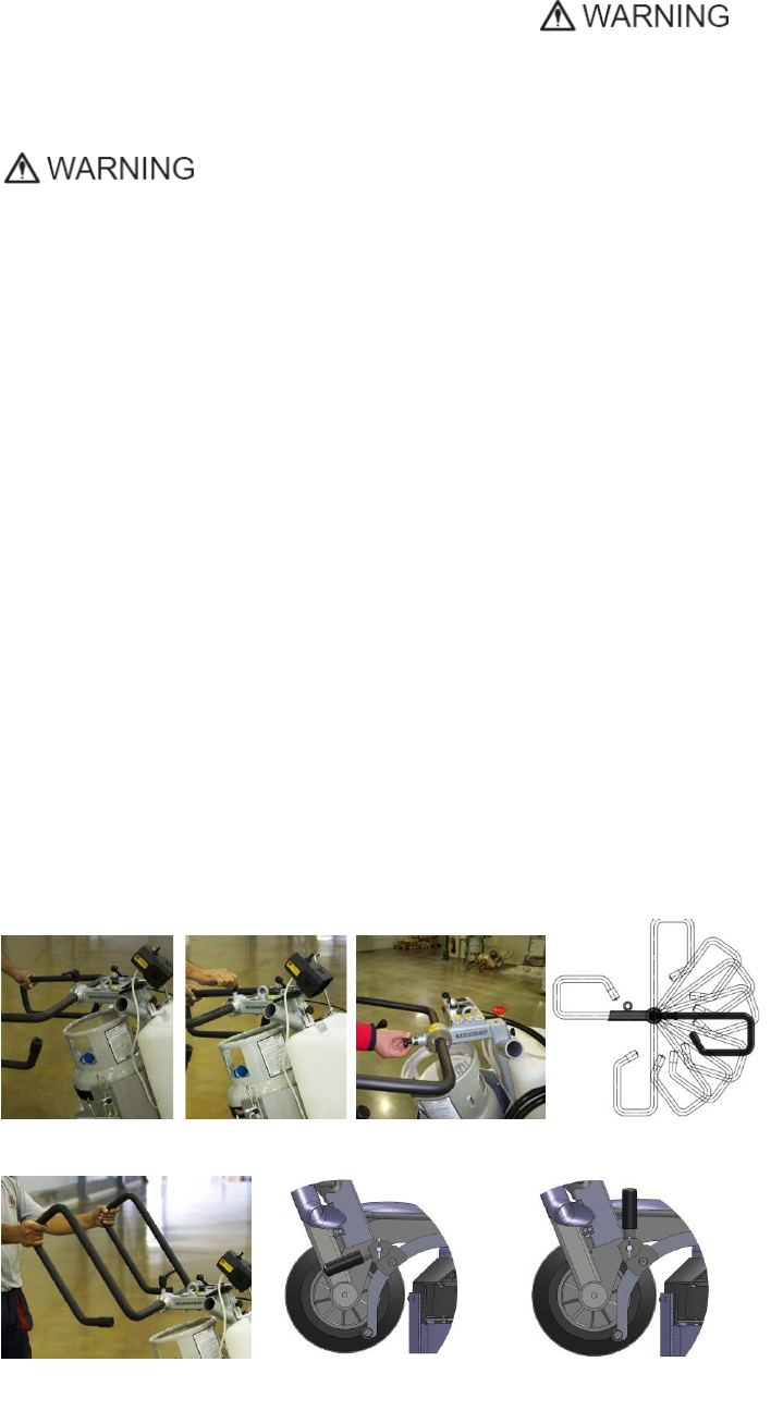
ADJUSTINGTHEHANDLE
TheHandleontheframeis
adjustableinheightandallowsthe
operatortoworkinacorrectand
safeposture(Fig.3.1,Fig.3.2,Fig.
3.3).Choosetheuprightpositionto
moveeasythemachine
(Fig.3.3).
Themachinesmanufacturedafter
Jan.12014arewithchanged
lockingofthehandleonthe
frame.Theunlockingisbypulling
thehandle(fig.3.2.1)Thelockingis
automaticallyunderactionofthe
spring.Fig.3.2.2showsallpossible
positionofthehandle.
Toavoidturningtheheadduring
transportshouldbeunscrewedthe
(butterfly,wing‐headed)screwand
move
the
leverfromtheposition
showninFig.3.4atoposition
Fig.3.4b.
WhenthemachineoperatesthelevermustbeinpositionshowninFig.3.4a,inordertorotatetheheadwhen
change
the
tool.
Superabrasive UserManual OriginalLanguageLavina®30G‐S 8/2014
11
LIFTINGTHEMACHINEFROMWORKINGTOTOOLMOUNTINGPOSITION
Pushthefronthandledownandswivelitto
thefront(Fig.3.5).Pull
the
handleupand
ensuretheheadisastableuprightposition,
for
mounting/dismountingthetool.Ensure
thatthewatertankisempty
before
flipping
themachine.Pulltheheadinupright
position(Fig.
3.6).
ThemachinesmanufacturedafterJan.12014
arewithchangedlockingofthefronthandle
asshownonthefig.3.6.1.
LIFTING
Liftingthemachinebycraneispossiblebyusingtheeyeboltmountedonthe
carriage
(seefig.3.7).Theeyeboltandmachineconstructionisratedonlyfortheweight
of
the
machine.Donotliftanyotherloadsonthemachine.Usealways
hoisting
equipment
ratedfor300kgor660
lbs.
STORAGE
AlwaysstoreandtransporttheLAVINA®Smachineinadryplace.Nevertransport
the
LAVINA®Smachineunprotected;itmaybedamagediftransported
unprotected
duringrainor
snow.
Whenduringthestorageofthemachinethetemperaturemayfall
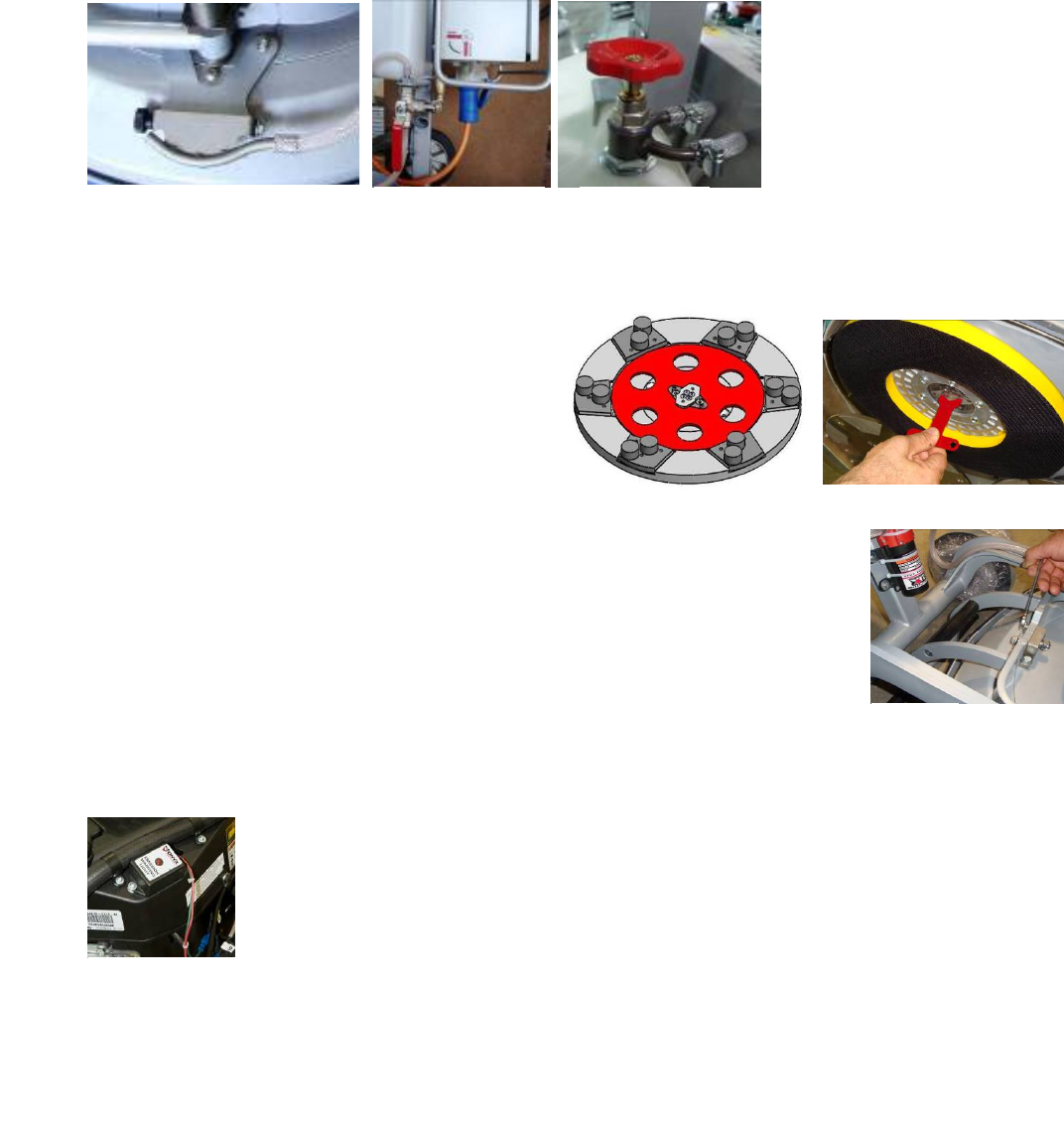
downtoorless32F(or0oC)youshouldemptythewaterfromthesystemusingfollowingsteps:
‐ Pulloutthehoseofthetank(Fig.3.8)
‐ Usingcompressedairblowoutthewaterfromthesystemforthetwopositionsoftheturn‐cock(Fig.3.9,Fig.3.10).
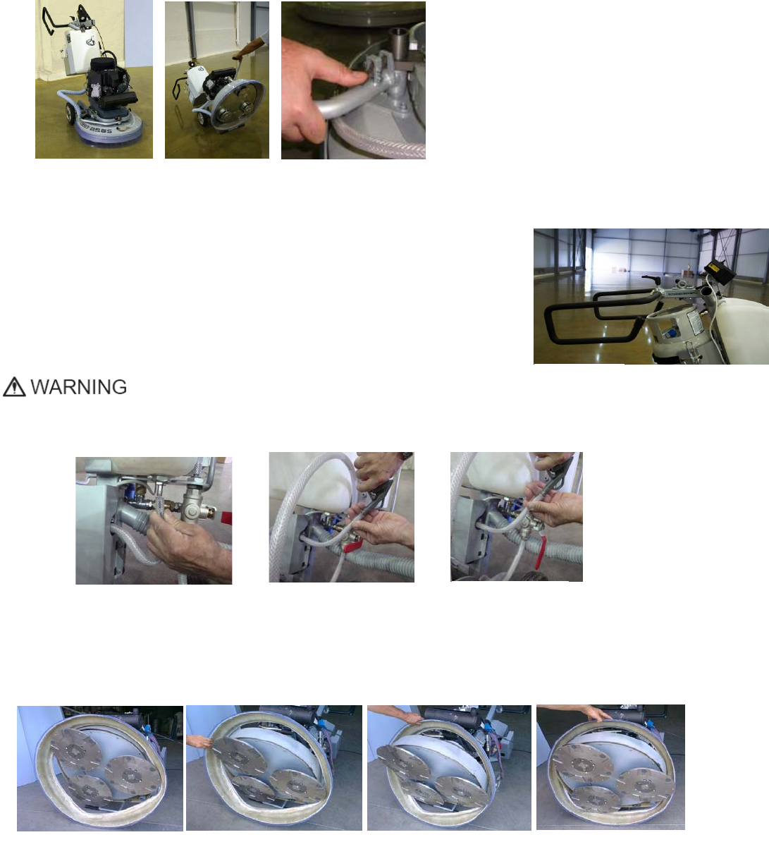
MOUNTINGOFGUARDASSEMBLY
SetthemachineinthepositionshownonFig3.11,turntheGuardAssembly(Fig3.12).PullbackwardstheGuardAssembly,you
havetobesurethattheToolholdershavepassedthroughit(Fig3.13).PuttheGuardAssemblyonposition(Fig3.14).
Dismountingmustbedoneinreversesequence.
F
g
ure 3.12 F
g
ure 3.13
F
g
ure 3.11 F
g
ure 3.14
Figure 3.7
Figure 3.8 Figure 3.9 Figure 3.10
Figure 3.5 Figure 3.6 Figure 3.6.1
Superabrasive UserManual OriginalLanguageLavina®30G‐S 8/2014
12
4.OPERATION
PRELIMINARYCONTROLS
Inspecttheworkingareaasexplainedinthesafetyinstructions.Forwetuse,fillinthewatertankorconnectthevacuum
extractorandensurethatthevacuumhoseisclearanditwillfollowthemachineeasily.
Makesurethebonnetairfilterontopoftheengineisclean.Itshouldbecleanedhourly.
Checktheengineoillevel,screwthedipstickintogetreading.Seetoitthetankisfillup(seealso“StoragePropanetanks).
TANKandFUELLINES‐Thetankshasalreadybeencoveredbutdothefuellinesshowanysignofwearandtear,suchascracksor
anycorrosion.Screwthebrassfuellinefittingontothetankservice‐valvehandtightonly.ThisconnectionMUSTbesecure
becausetheservicevalvehasasafetyvalveinsideit,whichwillonlyopenifthebrassfuel‐linefittingisCOMPLETELYseatedinto
theservicevalve.
WATERFLOWCONTROLUNIT
Theoperatorcanchoosethewater
sprayerinthefrontwhenthetapis
inthehorizontalposition(Fig.4.1),
thewaterwillsprayunderthecover
ofthemachinewhenthelevelisin
theverticalposition(Fig.4.2).The
flowregulatingvalvelocatedonthe
tank(Fig.4.2.1)isincreasingor
reducingthewaterflowtothe
working
area–infrontofthemachineorunderthemainheadcoverofthe
machine
/onlyformachinesproduced
after2013/
.
ADJUSTINGANDMOUNTINGTOOLS
Mountthetoolsonlyafterensuringthatthereis
enough
diamondbondmaterialleft.Besurethatthe
plates
are
alwayscleanbeforemounting.WARNING:Always
Securethe“Quickchange”padswiththesecurityplate
(Fig.4.3),lockwith
the
toolholderkey(Fig.5.3).Diamond
toolswithVelcroareattachedonthreefoamplatesof9
inch(Fig.4.4).Thefoamplates
are
ountedonthekey
lock(butterfly).Alwaysusethetoolholderkey
(Fig.5.3).
FRAMEBLOCKING(U‐JOINT]
Therelationbetweentheworkingheadandthetrolleyistheframeu‐joint,whichallows
rotationabouttwoperpendicularaxestobetterfollowtheprofileofthefloor.
Themovementalongtheoneaxiscanbefixedwithtwoscrews(Fig.4.5)andthatblockthe
lateralmovementofthemachine.
ALARM
EnviroGardemploysasensor(Fig.4.6)intheexhaustpathbetweentheengineandthecatalytic
mufflertodetecttheoxygencontentoftheexhaustbeforeitispassedthroughthecatalyst.The
oxygensensordoesnotreactto
nor
doesitmeasuretheCOcontentoftheexhaust.Itrespondsonly
tooxygen
content.
TheControlModuleissettoignorethereadingsfromtheoxygensensorduringthefirstthree
minutes
theengineisrunning.Thisperiodallows:Thesensortoreachastableoperating
temperature.
ThecatalystinthemufflertoreachthetemperaturenecessarytoreducethelevelsofCO,
nitrogen
oxides(NOx)andhydrocarbons(HC)inthe
exhaust.
ThemostcommoneventinwhichtheControlModuleshutsdownanengineiswhentheairfilterbecomesdirtyenoughto
restricttheairintakeflow,whichchangestheair‐fuelratiosuchthattheoxygensensorsignalisoutsidethecontrollimits.Once
theairfilterisproperlycleaned,operationofthemachinecanberesumed.
Figure 4.4
Fi
g
ure 4.3
Figure 4.5
Figure 4.6
Figure 4.2.1
Figure 4.1 Figure 4.2
Superabrasive UserManual OriginalLanguageLavina®30G‐S 8/2014
13
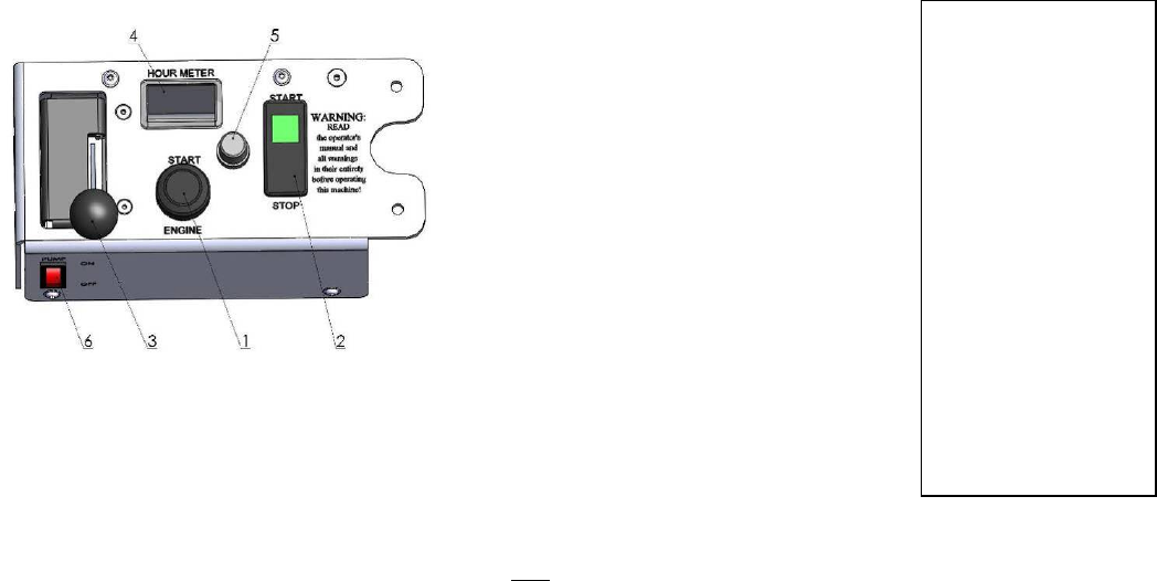
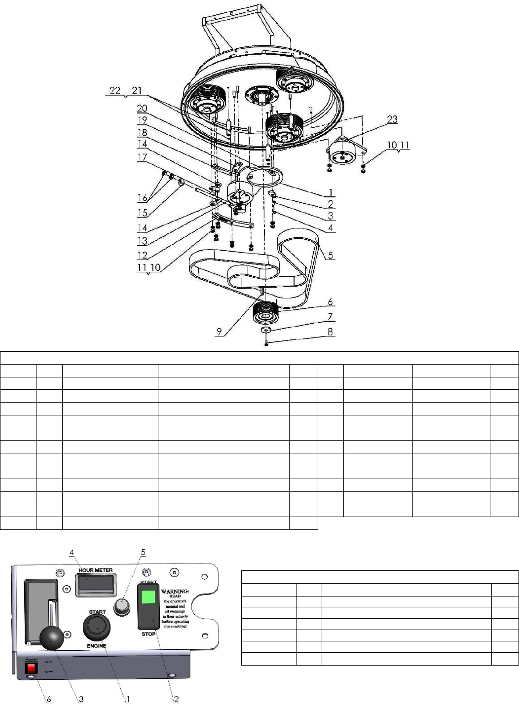
CONTROLBOARD
THECONTROLBOARD
1Start/StopEngineswitchTurnkeytotheright
forcontactfullrightforstartingtheengine,tostop
keytoleftfullleftiscontact
2Start/StopclutchStartwillelectronicallyactivate
thegrindingplatestospin,bypushingstopitwill
disconnectenginefromgrindingheads
3ThrottlePushforwardtoaccelerate.
4DigitalRPM/workingshoursindicatorWhenthe
motorrunsitindicatestherevolutionsperminute
ofthemotor,seetheconversiontabletoknowthe
rpmofthetools.Whenthemotordoesnotrun,it
indicatestheworkedhours.
Thehourmeterwillblinkbetween48‐52hoursasa
reminderforoilchange.
5FuseFuse30Ampsfortheelectricalsystem.
6WaterpumpswitchLightsorangewhenthewaterpumpisworking.
STARTINGTHEMACHINE
First,followthedirectionsinchapterSafetyDevicesandSafetyInstructions.Checkoillevel.
Open
(counterclockwise)theservicevalveonthepropanetankaboutoneandahalfturns.Next,seetoittheStart/Stopclutch
button
(2)isinstoppositioncheckthethrottle(3)intheIDLEposition.Thiscreatesavacuumnecessarytoopenthelock‐off
valve
inside
theregulator.Actuationofthethrottleleverwillkeepthelock‐offvalvefromopeningandtheenginefrom
gettingfuelso
the
enginewillnotstart.Propermaintenancewillinsureeasystarting.Engagestarter(1)foraMAXIMUMof
5to6secondsor
until
theenginefires.Seriousstarterdamagewillresultifthisisexceededandthewarrantymaynotapply.
Operatetheengineat
half
throttleforapproximatelytwominutesforproperwarm‐up.Thenadvancetofullthrottlefor
bestresults.Ifworkingwet,
add
watertothefloorsurface.Ifworkingdry,omitthisstep,andinstead,switchonthevacuum
unit.Finally,holdthemachine
firmly
andpushthestartoftheStart/Stopclutchbutton
(2).
OPERATINGTHEMACHINE
Guidethemachineinstraightlinesacrossthefloor,andwitheachnewlineoverlapalittlebitofthepreviouslycompleted
surface.
Workataconstantspeedallowingthetoolstimetoworkataspeedappropriateforthetools’gritsize.Avoid
vibrations.Do
not
stoptheLAVINA®Smachineinonespotwhilethetoolsarestillworkingbecausetheywillleavemarkson
thefloorsurface.
When
workingwet,openthewatertankperiodicallytoreleasewaterontothefloorsurface.Whenworking
dry,checkthefloor
surface
periodicallytoensurethatdustisnotaccumulatingonthesurface,alsocheckregularlyifyour
vacuumworks
properly.
STOPPINGTHEMACHINE
Thestoppingofthemachinemustbedonegraduallyuntilthemotorstops.Donotstopmovingthemachinebefore
arresting
the
clutchasthetoolscoulddamagethesurface.TostoppushStopclutchbutton(2),thenclose(clockwise)the
servicevalveon
the
propanetank.ALWAYSallowtheenginetorununtilitstopsfromlackoffuel.•ONLYINAN
EMERGENCYshouldthe
"stop"
positiononStart/StopEngineswitch(1)Disconnectthefuellinefromthetank.REMEMBER,
whenyouarefinishedwith
the
machine,storethepropanetankoutsidethebuilding,inaSECUREplaceawayfromheator
directsunlight.Usethe
Emergency
button(9)onlyinemergencyoruseittoswitchthepowertotallyoff.Remembernotto
holdthemachineinonespot
before
turningoffuntilthegrindingplatesstop
moving.
pmengine rpmtools
2000650
2100683
2200715
2300748
2400780
2500813
2600845
2700878
2800910
2900943
3000975
31001008
32001040
33001073
34001105
35001138
36001170
Figure 4.5

Superabrasive UserManual OriginalLanguageLavina®30G‐S 8/2014
14
5.TOOLSANDACCESSORIES
WEIGHTS
Superabrasiveoffersadditionalweightsforincreasingtheproductivityof
the
machine(Fig.5.1).Eachadditionalweightweighsabout64lbsor29kg.
Each
individualapplication,typeandconditionofsurface,powercapacityof
the
outlet,
etc.willdeterminethenumberofweightsyoucanusewithout
tripping
abreaker.
Theweightstacksontothreepostsaroundtheouterbowl
(Fig.5.2).
Theadditional
weightsdependonthetools;itisnotalwayspossibleto
add
weights.Sometools
worktooaggressivelyandthemachinecanstop.
The
weightcanbeorderedwith
itemnumberA
08.00.00.00.
TOOLHOLDERKEY
Thetoolholderkey(Fig.5.3)isusedforadjusting,mountinganddismountingof
thefoamplates.Alwaysusethekeyformounting.
ItemnumberisA03.00.00.00
FOAMPLATE
DiamondtoolswithVelcroaremountedonthefoamplate
(Fig.5.4).Thefoamplateismountedonthe“QuickChangeSystem”.
ItemnumberisLV‐13.5‐FP‐S
SECURITYPLATEFORQUICKCHANGEPADS
Plate(Fig.5.5)usedtoensurethe“Quickchange”pads.
ItemnumberisA38.00.02
Figure 5.3
Figure 5.4
Figure 5.5
Figure 5.2
Figure 5.1

Superabrasive UserManual OriginalLanguageLavina®30G‐S 8/2014
15
6.POPULARTOOLS
RECOMMENDEDTOOLS
QuickChange System and Tooling feature extremely fast and convenient tool changes,
and a long tool
life, providing for great longterm cost savings. The QuickChange pads
are produced in four different
bonds for super hard, hard, medium and soft concrete, in a
variety of grit sizes. They are offered with
1 or 2 buttons or rectangular segments, which allows you to customize the aggressiveness of
the cut.
Calibra grinding discs: our popular ceramic bond discs are designed for the removal of difficult
scratches
and they save you valuable time by eliminating the need for multiple passes with metal
tools. They can be
used wet or dry, and are best for hard concrete applications.
They are 3-inch, with included Velcro back attachment.
NATO® polishing discs feature a special resin formula designed for both wet and dry applications and a
unique design with
wide channels allowing for work on a cleaner surface and ensuring a quality polish. Available
in 3 and 4 in sizes. They are with
included Velcro attachment.
VHARR® Premium Polishing Pads are designed for mechanically polishing and restoring concrete; also
ideal for terrazzo and
hard stone floors. VHARR® pads are offered in a wide variety of diameters and grit
sizes to accommodate many applications.
Dry use is strongly recommended.
Shine Pro® are high quality diamondimpregnated pads for floor maintenance. Available in a variety of sizes, and
are great for
daily use. When used wet, they require only water (no wax or chemicals needed) and are a very
environmentally friendly solution
for maintaining floors.
Use only Superabrasive’s recommended tools. For more tooling options, visit www.superabrasive.com
Superabrasive UserManual OriginalLanguageLavina®30G‐S 8/2014
16
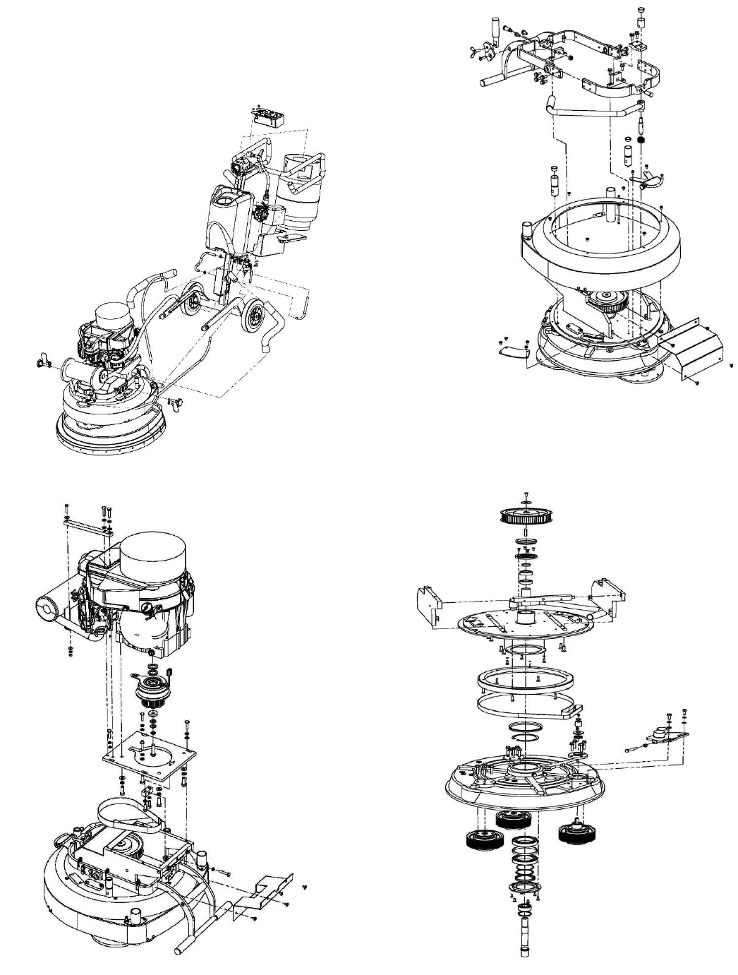
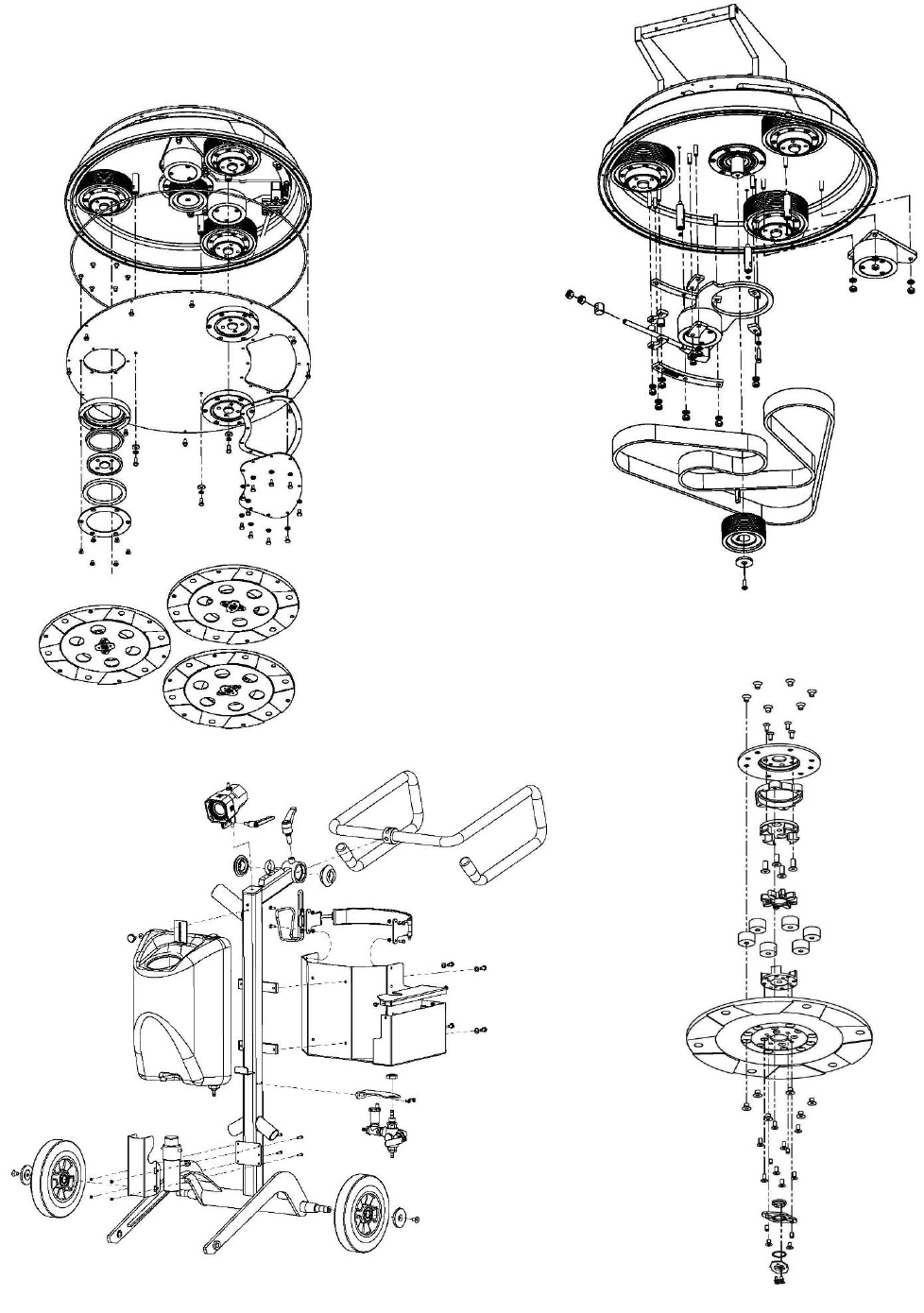
7.EXPLODEDVIEW
LAVINA®30G‐SGENERALEXPLODEDVIEW(FIG.7.1)
LAVINA®30G‐STOPCOVEREXPLODEDVIEW1(FIG.7.2)
LAVINA®30G‐SPLANETARYDRIVEEXPLODEDVIEW(FIG.7.3)
LAVINA®30G‐STOPCOVEREXPLODEDVIEW2(FIG.7.4)
Figure 7.3 Figure 7.4
Figure 7.1
F
Figure 7.2
Superabrasive UserManual OriginalLanguageLavina®30G‐S 8/2014
17
LAVINA®30G‐SBOTTOMCOVEREXPLODEDVIEW1(FIG.7.5)
LAVINA®30G‐SBOTTOMCOVEREXPLODEDVIEW2(FIG.7.6)
LAVINA®30G‐SCARRIAGEEXPLODEDVIEW(FIG.7.7)
LAVINA®30G‐STOOLHOLDEREXPLODEDVIEW(FIG.7.8)
Figure 7.6
Figure 7.5
Figure 7.8
Fi
g
ure 7.7
Superabrasive UserManual OriginalLanguageLavina®30G‐S 8/2014
18
8.MAINTENANCEANDINSPECTION
REMARK
Tamperingw/EmissionControlSystemProhibited
FederallawandCaliforniaStatelawprohibitsthefollowingactsorthecausingthereof:(1)theremovalorrendering
inoperative
byanypersonotherthanfarpurposesofmaintenance,repair,orreplacement,ofanydeviceorelementatdesign
incorporated
intoanynewengineforthepurposeofemissioncontrolpriortoitssaleordeliverytotheultimatepurchaseror
whileitisin
use,
or(2)theuseoftheengineaftersuchdeviceorelementofdesignhasbeenremovedorrendered
inoperativebyany
person.
Amongthoseactspresumedtoconstitutetampering,involvetheparts/systemslisted
below:
Carburetorandinternal
parts
Spark
plugs
Magnetoorelectronicignition
system
Fuelfilter
element
Aircleaner
elements
Crankcase
Cylinderheads
Breatherchamberandinternalparts
Intakepipeandtube
MECHANICALPARTS
Partssuchasthebelt,sealrings,caprings,spiders,buffers,guardassembly,tiresaresubjecttowearandshouldbereplaced
asneeded.
CLEANING
Keepyourmachineclean.Cleaningthemachineonaregularbasiswillhelpdetectandsolvepotentialproblemsbeforethey
cause
damagetothemachine.Mostimportantly,checkandcleanthetoolplateconnections,vacuumhoses,watertankand
the
Propane
installation.
CHECKHOURLY
BONNETFILTER‐Makesurethebonnetairfilteratoptheengineisclean.Itshouldbechangedhourlyandthoroughly
cleaned
beforereuse.Thesamefortherecoildustfilter.Ifneglectedtheenginewilloverheatandcarbonmonoxideemissionswill
elevate.
CHECKDAILY
AfteroperatingtheLavina®Smachine,theoperatorshouldconductavisualinspection
of
themachineduringcleaningthewholemachine.Anydefectshouldbesolved
immediately.
Checkoillevel
daily.
Toolholders:Buffersandspidersareconsumablesandmustbevisuallycheckeddaily
and
replacedifneeded.SeeflangesordiscsaremountedlockedwellinplaceThekey
lock
holders(butterflies)shouldbealso
checked.
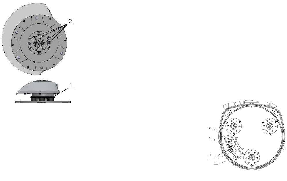
Checktherubberbuffersandfixingoftheholders.Theflangeholdingthebuffers
(Fig.8.1
1)hastobefirmlyfixedtotheunit.Agapseentheremeansthatthereareloose
screws
fixingtheholder.Thescrewshavetobetightened immediatelyforsafe
operation.
Working withloosescrewsontheholdercouldalsocausebaddamageonthe
machine.
Tighteningforceofthescrewshastobe25...30N.m(18...22
ft/lbs).
Itisveryimportanttoregularlycheckthescrews(Fig.8.1 2),thatfix
the
"Quickchange"holdertothesafetypart,sothat
holderwillnotflyawayifthebuffers
getdamaged.
“Quickchange”sleevesshouldbeclean.Thetension
oftheplanetarybeltcanbe
daily
checkedbymovingthemainheadandfeelingthe
resistanceofthemovingpulleys,if
the
beltslipstensionimmediately,likedescribedin
thechapterTroubleshooting
.
CHECKANDREPLACEAFTERTHEFIRST8WORKINGHOURS
Replacetheoilintheengineafterthefirst8hourswork,accordingtotheinstructions
of
theengine
manufacturer.
Alwaysuse30HDor10W30engineoilwithallofthefollowingratings:SF,SG,and
CC
CHECKANDREPLACEAFTERTHEFIRST15WORKINGHOURS
Checkthebelttensionafter15hoursworkingwiththe
machine.
Thebottomcoverhasacontrolcover(Fig.8.2)thatallowsfastandeasycontrol
and
correctionofthebelt.Itisrecommendedtocheckthetensionofthebeltafterthefirst15hoursandtotightenifnecessary.
For
thecorrecttension,seeTROUBLESHOOTING“mountingthebelt”.Everytimeyouopenthecontrolcover,mountbackall
the
screwswith
washers.
Figure 8.2
Figure 8.1
Superabrasive UserManual OriginalLanguageLavina®30G‐S 8/2014
19
CHECKANDREPLACEEVERY50WORKINGHOURS
Changeengineoil,whilechangingcheckforleakageofengineoilatthevariousseals.Thehourmeterwillblinkbetween
48‐52
hoursasareminder./"EngineOilCapacity"is1.5L(1.6US.qt)whenoilfilterisnotremoved1.7L(1.8US.qt)whenoil
filter
isremoved/.
Recommended Oil Change
Intervals
Donotexceedthe50‐houroilchangeinterval.Oilchangesmorefrequentthan25hourswillgiveevenlongerenginelife.In
any
case,alwaysuse30HDor10W30engineoilwithallofthefollowingratings:SF,SG,andCC.makesuretheoillevelis
maintained
atthe"FULL"
level.
CHECKANDREPLACEEVERY200WORKINGHOURS
Every200workinghourstheoperatorshouldinspectallpartsofthemachinecarefully.Mostimportantly,inspectandclean
the
toolplateconnections,vacuumhosesandwatertank.Also,checkthewaterflow.Checktheguardassembly.Make
certain
the
wheelsarecleanandrotateproperly.Inspectthecontrolbuttons.Iftherearedefectivecontrolparts,they
shouldbe
replaced
immediately.Replacewornvacuum‐andwater
hoses.
Carefullyinspectthesealringsandbearingsofthegrindingunits,andreplaceanyshowingsignsofexcessivewear.For
more
information,refertochaptertroubleshooting
below.
Dismountthetoolholders(SeeTroubleshooting)replaceallparts(Spider,buffers,sealercaps,“O”rings)withthe
slightest
damage
orconsume.Openthecheckingcoveronthemotorbasetocheckoftheplanetarydrivingbelt,bymovingthemain
head
thebeltshouldnotslipontheplanetarypulleyanddrivethepulleys.Returnmachinetoauthorizedservicecenterfor
overall
checkupoftheEngine.ForPropanesafety,havethemachineservicedbyaCertifiedTechnician,includingemission
check.
CHECKANDREPLACEEVERY400WORKINGHOURS
Besidesthechecksof200workinghours,replacesealerandV‐ringslikedescribedinchapter“TROUBLESHOOTING
REPLACING
BELTANDPULLEYUNITS.Checkifbeltsandbearingsareingoodcondition,changeif
needed.
ReturnmachinetoauthorizedservicecenterforoverallcheckupoftheEngine.ForPropanesafety,havethemachineserviced
by
aCertifiedTechnician,includingemission
check.
VACUUM
Asstatedpreviously,frequentlycheckhosesandotherpartsforclogging.
WATERLEAKS
Replaceanyleakingpartsimmediatelyasthewatercoulddamageyourmachine
MECHANICALPARTS
Partssuchasthebelts,sealrings,caprings,spidersandbuffersandguardassemblyaresubjecttowearandshouldbereplaced
asneeded.
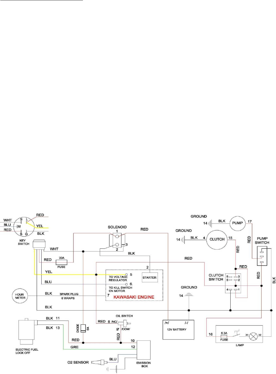
ELECTRICALSYSTEM
Dustshouldnotenterthecontrolbox,asitwilldestroythecontacts.Remove(blowout)anydustpresent.
ElectricalschemeswithKawasakiEngine
Superabrasive UserManual OriginalLanguageLavina®30G‐S 8/2014
20
9.TROUBLESHOOTING
9.1ENGINE
Whentroublesoccur,be sure to check the simple causeswhichatfirst,mayseemtooobvioustobeconsidered.Forexample,
a
startingproblemcouldbecausedbyfuelstarvationduetoanemptypropanecylinderoranunopenedservicevalve.Ifyou
do
not
checkforthis,starterburnoutcould
result.
SomeTroublesand
solutions:
Surging
idle
Tosmoothouttheengines'idlecharacteristics,adjustmentisprovidedbyanidlescrewonthelowerleftsideofthecarburetor
as
viewedfromtheoperator'sposition.Thescrewisbrightsteeland1/4"indiameterwithaPhillipsheadonit.Rotatingthe
screw
clockwisewillincreasetheidlespeedandthisshouldcurethe"surgingidle".Ifitdoesnot,callourcustomer
service.
Enginestartsandidles,butwillquitasthethrottleis
advanced
Itispossiblethatthepropanetank'sservicevalveisfaulty.Tocheckforthis,closethevalvecompletelyandthenreopen
very
slowlywhileyoulistenfora"click"whenthegasbeginstotravelthroughthevalve.Ifyouhearthisveryslightnoise,the
valve
is
onlypartiallyopening.Thisallowsenoughgasthroughtostartandidletheengine,butnotenoughforfullthrottle
operation.
As
thethrottleisincreased,allowingmoreairtoentertheintake,theenginewillquitfromfuelstarvation.Call
yourdealeror
the
factoryforinstructionsonwheretohavetheservicevalvereplaced.Meanwhile,togetby,youcan
continuetoopenthe
service
valveuntilyoudonotheara“click"andthentheenginewillrunnormally.Ifitdoesnot,call
yourcustomer
service.
Starterbarelyturnstheengineoverorthesolenoidjust
clicks
Thebatteryislikelylowincharge.Thiscanberemediedbyrechargingthebatteryusinga12Voltbatterychargerat
4.12
amperes.Thebatteryislocatedundertheframeattherearofthebuffer.ThepositivepostistheonewiththeREDcable
attached
toit.Followtheinstructionsthatcamewiththebatterycharger.REMINDER:thiswillcontinuetohappenunlessyour
engineis
run
forsufficienttimebetweenstartstorechargethe
battery
9.2CHECKINGANDCHANGINGOIL
Checktheengineoillevel,screwthedipstickintogetreading.Whilechangingengineoil,checkforleakageofengineoilat
the
variousseals.Thehourmeterwillblinkbetween48‐52hoursasa
reminder.
Recommended Oil Change
Intervals
Donotexceedthe50‐houroilchangeinterval.Oilchangesmorefrequentthan25hourswillgiveevenlongerenginelife.In
any
case,alwaysuse30HDor10W30engineoilwithallofthefollowingratings:SF,SG,andCC.makesuretheoillevelis
maintained
atthe"FULL"
level.
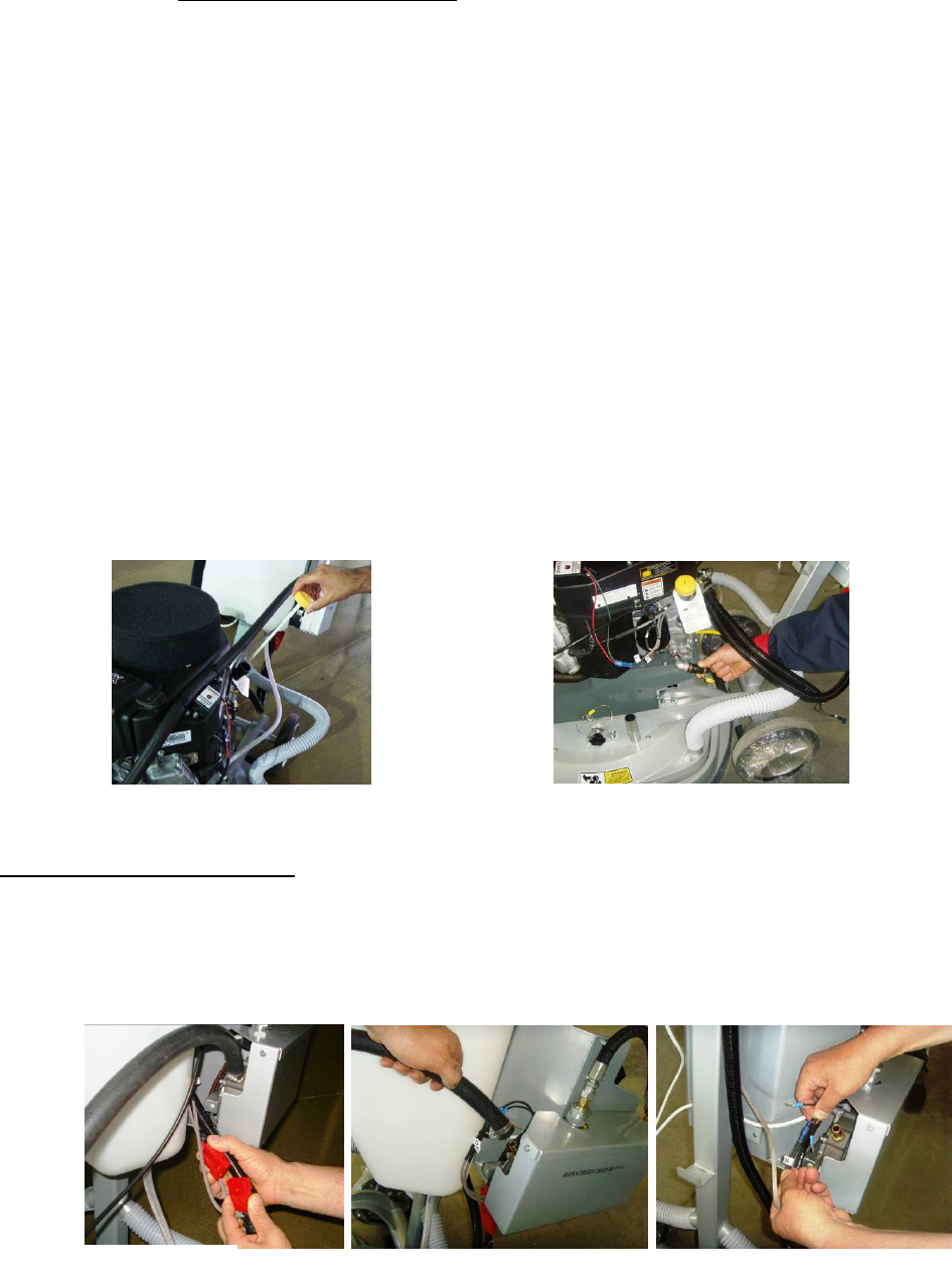
9.3SEPARATINGTHEHEADFROMTHECARRIAGE
Pleasenotethatthepropanecylinderhastoberemovedandstoredoutsidebeforeanymaintenanceorreparationisdone.
Figure 9.2.1 Figure 9.2.2
Figure 9.3.1 Figure 9.3.3 Figure 9.3.2
Superabrasive UserManual OriginalLanguageLavina®30G‐S 8/2014
21
Pulltheconnectorofthebattery(Fig.9.3.1),pulloutthePropanehose(Fig.9.3.2),theconnectorsofthelamp(Fig.
9.3.3),
dismountthecontrolpanel(Fig.9.3.4),andtakeoffallwaterandvacuumhoses(Fig.9.3.5).Removethetank(Fig.9.3.6).
Nowit
is
possibletoseparatetheheadbyremovingthepins;twopeopleareneededtodothisoperation:onepersonholds
thecarriage
the
otherpullsthepins(Fig.
9.3.7).
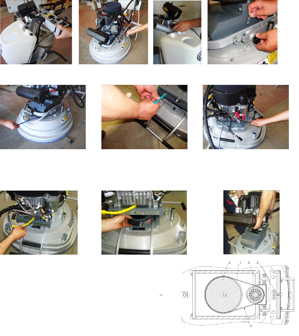
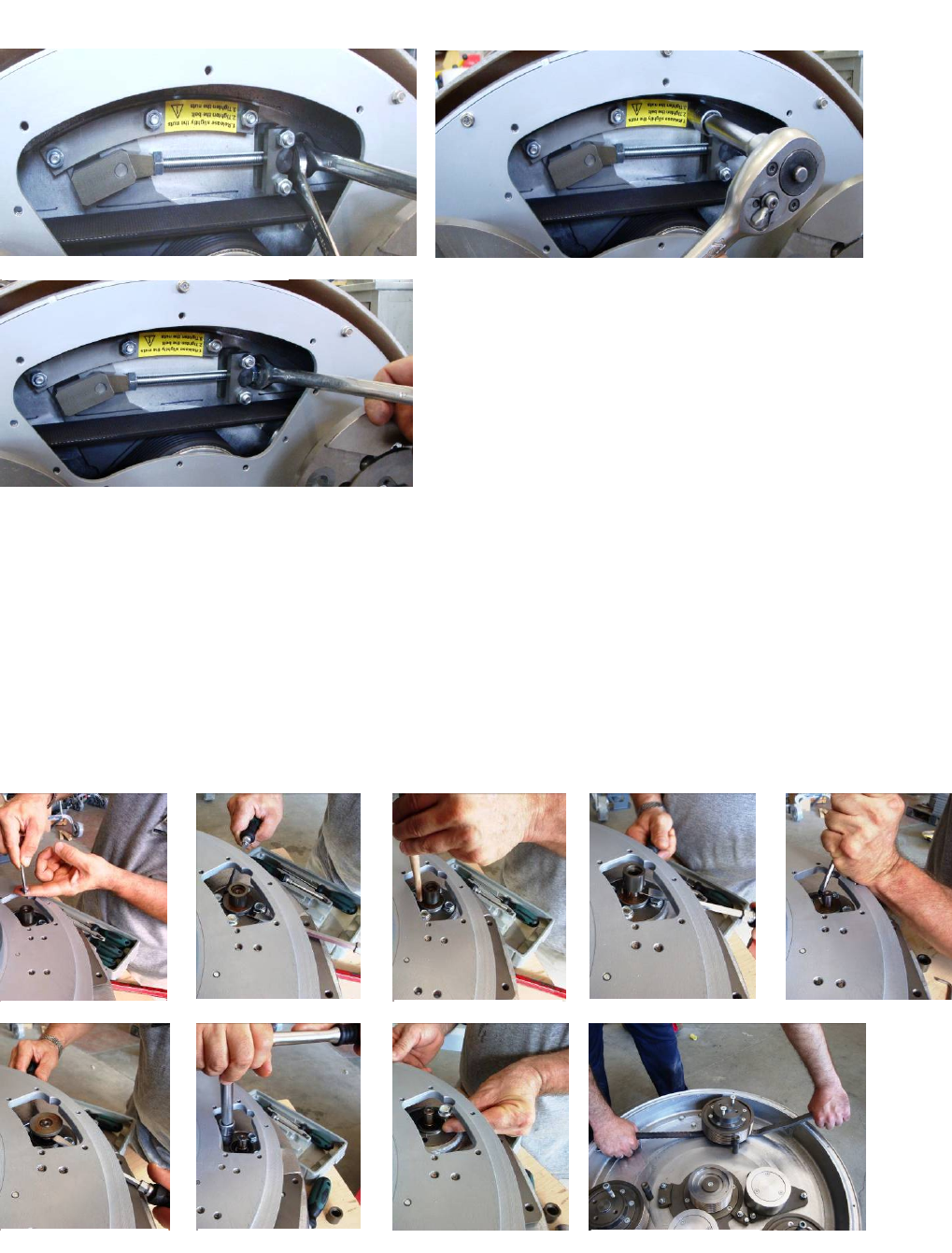
9.4DISMOUNTING/MOUNTINGTHEENGINE
Separateheadfromcarriage(seepreviouschapter).Removefront(Fig.9.4.1)andbackbeltprotection(Fig.9.4.2).Loosethe
motorbaseplate(Fig.9.4.3),releasethetensiondevice(Fig.9.4.4),andtakeoutthebelt(Fig.9.4.5).Takeofftheengine(Fig.
9.4.6).
Reassembleinthesamemanner.(Fig.9.4.7),Tensionthebeltwithbolt(4)
on(fig.9.4.6)or(fig.9.4.4)ThebelttensioncanbetestedwithaFrequency
tensionTesterOptibelt3TT‐(218Hz)ormanualbypushingwithaforceof
6kgor13lbsinpointA,thedeflectionofthebeltmustbe3,1mmor+1/8
Inch
ATTENTION:
NEVER“OVER”TENSIONTHEBELT,THEBELTWILLBEDESTROYEDANDIT
WILLNEVERRECOVERITSORIGINALTENSION
Figure 9.3.4 Figure 9.3.5 Figure 9.3.6 Figure 9.3.7
Figure 9.4.1 Figure 9.4.2 Figure 9.4.3
Figure 9.4.4 Figure 9.4.5 Figure 9.4.6
Figure 9.4.7
Superabrasive UserManual OriginalLanguageLavina®30G‐S 8/2014
22
9.5REPLACINGTHECLUTCH
Incasetheelectricclutchhastobereplaced,removetheengine(seeprevious
chapter)
andlayitonitssidewiththeoildrainageup(Fig.9.5.1)andloosethe
frontnuttodismounttheclutch(Fig.9.5.2andFig.9.5.3).
Reassembleinthesamemanner.Donotforgettomountbackthewashersonthe
shaft
(Fig.9.5.4).Thetorqueonthefrontnut(Fig.9.5.3)tomountthepulleyandclutch
should
be70Nmor55ft
lbs
(Fig.9.5.2andFig.9.5.3)
.
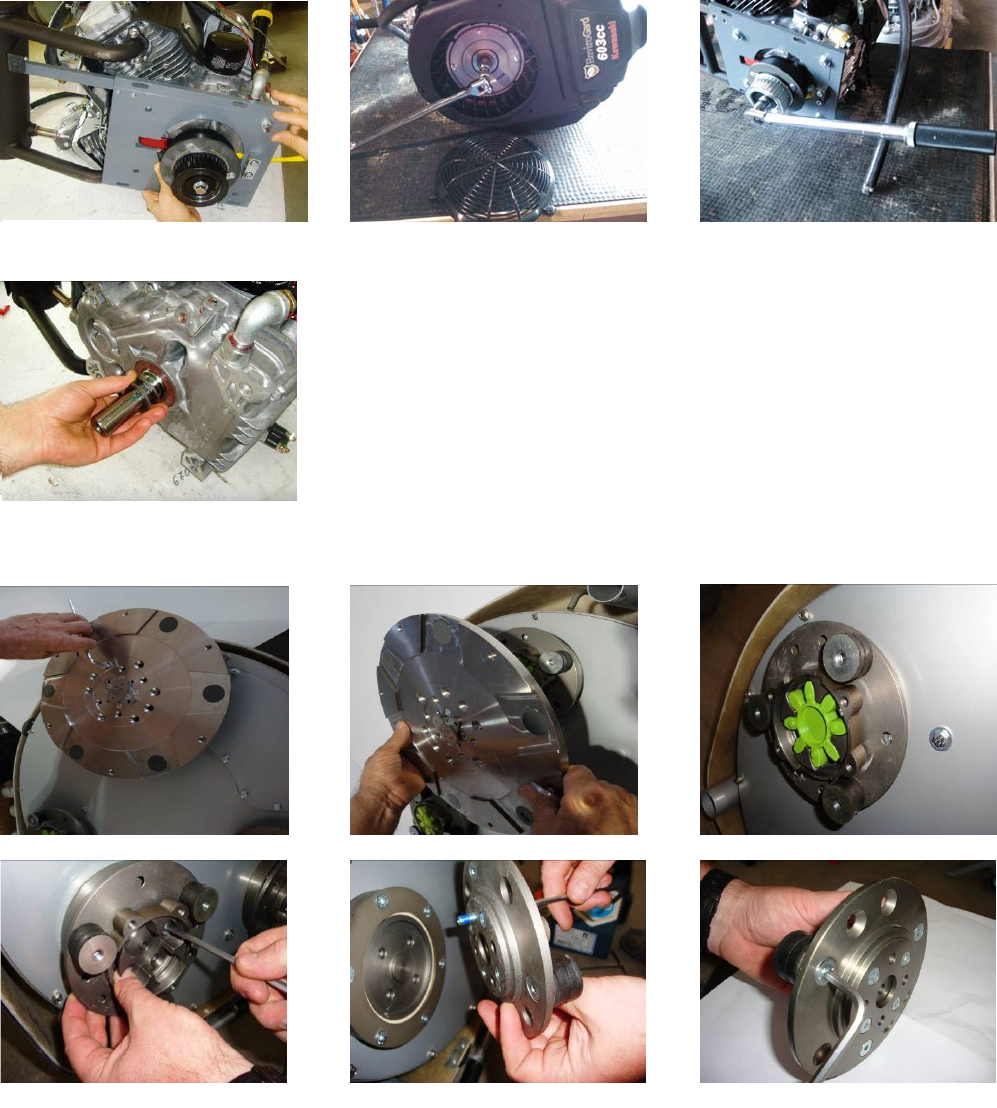
9.6DISMOUNTINGANDMOUNTINGTOOLHOLDERSTOCHANGEBUFFERSANDSPIDERS,
CHANGINGV‐RINGSANDFELT‐RINGS
Tocheckorreplacethebuffersandthespiders,thetoolholdershavetobedismounted.Removethecountersunkscrewson
top
ofthebuffer(Fig.9.6.1).Takethediscoff(Fig.9.6.2),thespidercanberemovedorreplaced(Fig.9.6.3).Bylooseningfour
Hex
cap
bolts(Fig.9.6.4),thedisccomesloose(Fig.9.6.5)andthebufferscanbereplaced(Fig.9.6.6).Attention,whenmounting
alwaysuse
the“blue”threadlockingadhesive,exceptontheboltsusedtolockthebuffers(Fig.9.6.5).Alwaysusetheoriginal
bolts.
Dependingonthenumber(3,4,or6)ofbuffers,theholdercanbemoreflexibleor
rigid.
Figure 9.6.1 Figure 9.6.2 Figure 9.6.3
Figure 9.6.4 Figure 9.6.5 Figure 9.6.6
Figure 9.5.1 Figure 9.5.2 Figure 9.5.3
Figure 9.5.4
Superabrasive UserManual OriginalLanguageLavina®30G‐S 8/2014
23
Figure 9.6.7 Figure 9.6.8 Figure 9.6.9 Figure 9.6.10
Whenthetoolholderisdismounted,youcanchangethesealers(V‐Ringand
Felt‐Ring).
TakeoutFelt‐Ring,AdaptorandV‐Ring.Beforemountingcheckonwhichsidetheadaptor
is
fitting,rememberthecorrectside.MounttheV‐RingwiththesmallestlipoftheVto
inside
(Fig.9.6.7)justpushtheV‐ringsothetopisonthesamelevelasthepulleytop(Fig.9.6.8).
Then
taketheadaptorinthecorrectwayandpushtheV‐Ringdownwiththeadaptor(Fig.9.6.9).
The
lowestlipoftheV‐Ringshouldonlybarelytouchitsglidingsurface;alsoneverpushthe
V‐Ring
downwithfingers.MountnowtheFelt‐ringontop(Fig.9.6.10).Closethesealerswith
the
cap(Fig.9.6.11).
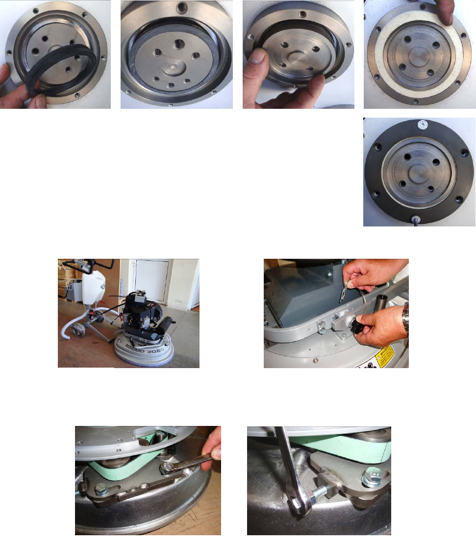
9.7TENSIONINGANDREPLACINGTHEPLANETARYBELT
Ifthebeltslipsorisbroken,separatethecarriagefrommainhead(Fig.9.7.1).Takeoffhandles,fork,topframe,and
weight
holderssoyoucanpushupthetopcover(Fig.
9.7.2).
9.8TENSIONINGUSEDPLANETARYBELT
Noticingspeedlostinplanetarymovementitispossibletotensionthebeltforplanetarymovementas
described
in9.9:Mountingandtensioninganewplanetary
belt.
Figure 9.8.1 Figure 9.8.2
Figure 9.6.11
Figure 9.7.1 Figure 9.7.2
Superabrasive UserManual OriginalLanguageLavina®30G‐S 8/2014
24
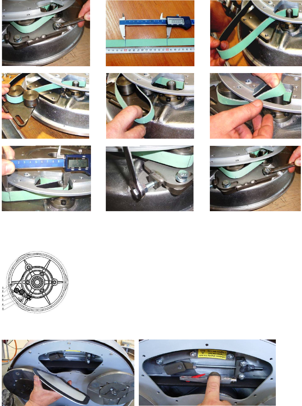
9.9 MOUNTINGANDTENSIONINGANEWPLANETARYBELT
Completelydismountthetensioningdevice(Fig.9.9.1).Make2signsonthedismountedbeltexactly10cmoutofeachother
(belt
withouttension)(Fig.9.9.2).Thepurposeistomeasure10.2cmonthebeltintensionwhatisatensionof2%.,amaximum
of
2.5%
is
allowed.
ATTENTION:NEVER“OVER”TENSIONTHEBELT,THEBELTWILLBEDAMAGEDANDITWILL
NEVERRECOVERITSORIGINALTENSION
Mountthebeltbackaroundtheplanetarypulley;seethatthebeltisbehindthedrivingpulley
(Fig.
9.9.3).Putthebeltaroundtheleftrollerofthetensioningdevice(Fig.9.9.4).Putthe
tensioning
devicebackinplaceandpullthebeltfromtherollerontherightside(Fig.9.9.5).Put
the
belt
aroundthedrivingpulley(Fig.9.9.6).Begintotensionuntilthemeasureof10cm
between
the
marksbecomes10.2cm(Fig.9.9.7)(Fig.9.9.8).Tightenthetensioningdevicewhile
turning
thebolt
movetheplanetaryheadsothebeltcanslide.(Fig.9.9.8).Donotforgettolock
the
tensioning
device
(Fig.9.9.9).
9.10CHECKINGTHETENSIONOFTHEBELT
Figure 9.9.6
Figure 9.9.1
Figure 9.9.4
Figure 9.9.2 Figure 9.9.3
Figure 9.9.5
Figure 9.9.7 Figure 9.9.8 Figure 9.9.9
Figure 9.9.10
Superabrasive UserManual OriginalLanguageLavina®30G‐S 8/2014
25
Open the checking cover to reach the belt and tension device (Fig. 9.10.1). While tensioning check
regularly
tension. Push the belt down and with a pressure of 71N. This is approximately 7 kilograms or 15 pounds
with
this pressure the belt should move 3.5-4 mm or 1/8”. It is recommended that the tensioning of the belt
be
measured with Optikrik II Device (Measuring range: 500-1400 N) (Fig. 9.10.2) The original pressure P=1400
N
and after working a while it is P=1100 N. ATTENTION:
NEVER“OVER”TENSIONTHEBELT,THEBELTWILLBEDESTROYEDANDITWILLNEVERRECOVERITSORIGINAL
TENSION
Loosenthecontranuts(Fig.9.10.3),lightlyloosenthethreeboltsofthetensiondevice(Fig.9.10.4),andadjustthetensionwith
the
nutseenin(Fig.9.10.5).Whentherighttensionisreached:closethecontranutsandthethreeboltsofthe
support.
Reassemble
inthesame
manner.
PLEASEMAKESUREYOUCHECKTHETENSIONOFTHEBELTAFTERTHEFIRST15HOURSOFOPERATION
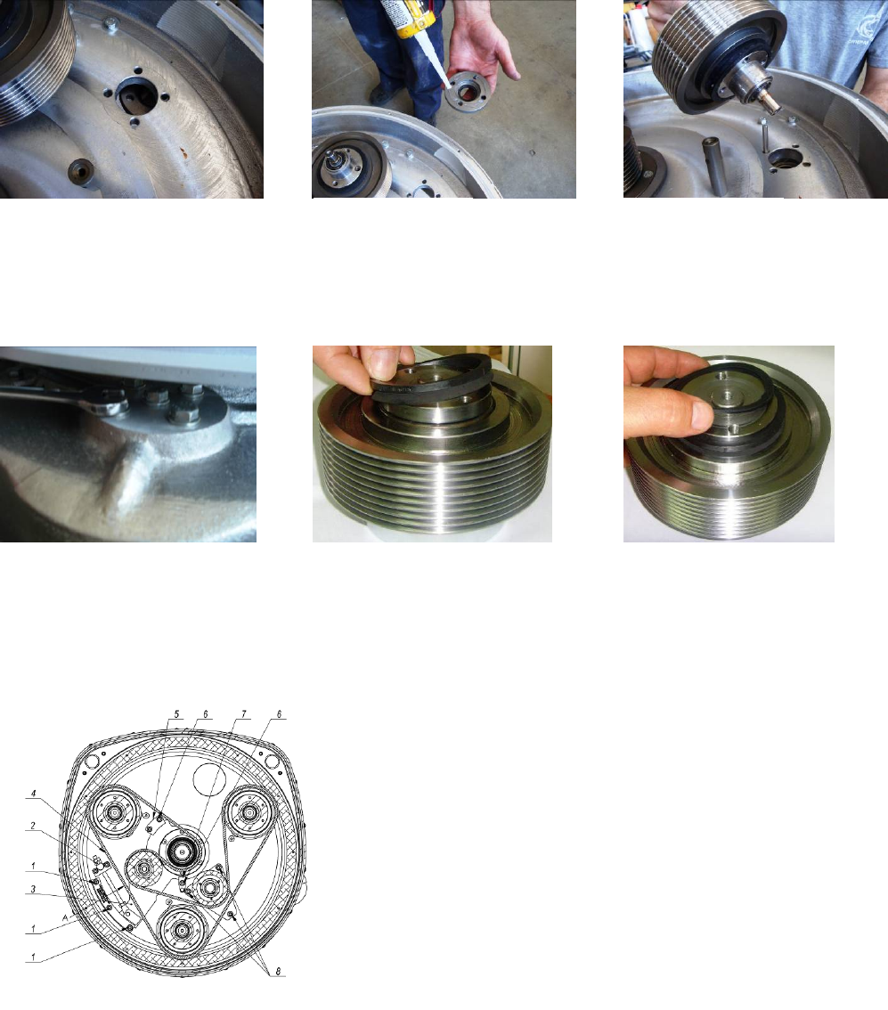
9.11REPLACINGTHEPULLEYUNITS
Takeoffengineasearlierdescribed,dismountguard,frameandtopcoveraspreviousdescribed.
Figure 9.10.3
Fi
g
ure 9.10.2
Figure 9.10.1
Figure 9.10.4
Figure 9.10.5
Figure 9.11.1
Figure 9.11.6
Figure 9.11.5
Figure 9.11.7
Figure 9.11.4
Figure 9.11.3
Figure 9.11.2
Figure 9.11.9
Figure 9.11.8
Superabrasive UserManual OriginalLanguageLavina®30G‐S 8/2014
26
Dismountingthedrivingpulley:takethetopscrewouttoreleasethebushing(Fig.9.11.1),pushthebushingtogetherwith
the
washerup(Fig.9.11.2),pushwasherdownofthebushing(Fig.9.11.3).,takebushingout(Fig.9.11.4),pushkeyout
(Fig.9.11.5),
nowthewasherreleases(Fig.9.11.6),dismountsealercap(Fig.9.11.7)(Fig.9.11.8),thepulleycanbereleasedwithtwo
crowbars
butdonotuseexcessiveforce(Fig.9.11.9),pushthesealercaptodismount(Fig.9.11.10),bymountingbacksecurewith
sealant
(Fig.9.11.11),centertheholestomountthepulley(Fig.9.11.12).
Thetwootherpulleys:loosenthefiveboltsofeachpulleybetweenthebaseplateandthemotorbasedisc(Fig.9.11.13).An
oil
sealring(Fig.9.11.14)andaseal(Fig.9.11.15)shouldbeplacedontopofthepulleybefore
mounting.
9.12MOUNTINGTHEBELT
Seeheretheschematicofthebeltonthepulleys(Fig.9.12.1).
Todismount/mountthebelt,followthetensioninginstructionin
chapter:
Checkingthetensionofthe
belt.
Figure 9.11.13 Figure 9.11.15 Figure 9.11.14
Figure 9.11.10 Figure 9.11.11 Figure 9.11.12
Figure 9.12.1

Superabrasive UserManual OriginalLanguageLavina®30G‐S 8/2014
27
10.DISPOSAL
Ifyourmachineaftertimeisnotusableorneedstobereplaced,sendthemachinebacktoSuperabrasiveoralocal
distributor,
whereaprofessionaldisposalcomplyingwiththeenvironmentlawsanddirectivesis
guaranteed.
11.MANUFACTURER’SCONTACTS
IfyouneedtocontactSuperabrasiveInc.withtechnicalsupportquestions,belowisthecontactinformation.
Address: 9411JacksonTrailRoad,HoshtonGA30548,USA
Email: info@superabrasive.us
Tel.: 7066581122
Fax: 7066580357
Website:www.superabrasive.com
Superabrasive Owner’sManual–LAVINA®30G‐S8/2014
28
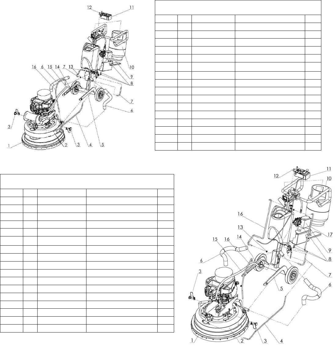
12.SPAREPARTS
ASSEMBLYANDPARTSSPECIFICATIONS
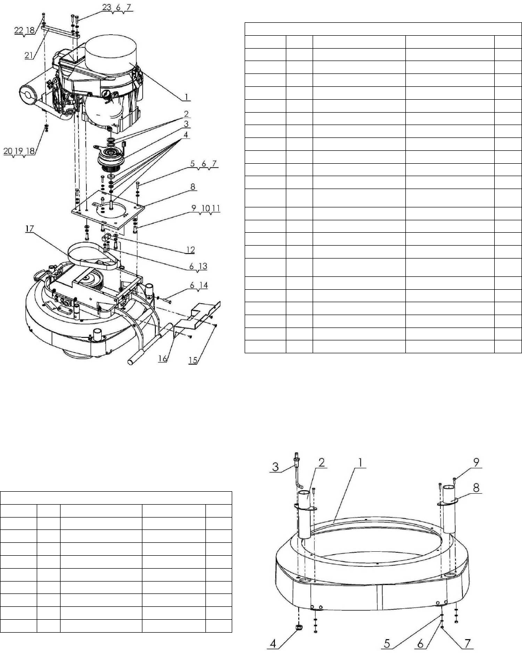
12.1LAVINA®30G‐SGENERALPARTS
/FORMACHINESPRODUCEDBEFOREJAN.12014/
Model No. Item No. Description Pcs.
L30G-S 1 L30-05.00.00.00 Guard Assembly 1
L30G-S 2 L30GS-10.00.00 Main head 1
L30G-S 3 L25GS-03.00.00 Pin Assembly 2
L30G-S 4 MAR8.110 Tube 1
L30G-S 5 L25GS-20.00.00 Carriage 1
L30G-S 6 D40L700 Vacuum Hose 2
L30G-S 7 MAR8.25 Tube 2
L30G-S 8 L25G-26.00.00 Regulator set 1
L30G-S 9 CC01-25968 12V Battery & Wire Connector 1
L30G-S 10 W2504 Propane Tank 1
L30G-S 11 L25GS-40.00.00 Control Board Ass. 1
L30G-S 12 M6X10ISO7380F Screw 2
L30G-S 13 10-16DIN3017 Clamp 3
L30G-S 14 F0708750 Clamp 1
L30G-S 15 W2660 Tube 1
L30G-S 16 MAR8.84 Tube 1
12.1LAVINA®30G‐SGENERALPARTS
/FORMACHINESPRODUCEDAFTERJAN.12014/
Model No. Item No. Description Pcs.
L30G-S 1 L30-05.00.00.00 Guard Assembly 1
L30G-S 2 L30GS-10.00.00-01 Main head 1
L30G-S 3 L25GS-03.00.00 Pin Assembly 2
L30G-S 4 MAR8.110 Tube 1
L30G-S 5 L25GS-20.00.00-01 Carriage With Control Box 1
L30G-S 6 D40L700 Vacuum Hose 2
L30G-S 7 MAR8.25 Tube 1
L30G-S 8 L25G-26.00.00 Regulator set 1
L30G-S 9 CC01-25968 12V Battery & Wire Connector 1
L30G-S 10 W2504 Propane Tank 1
L30G-S 11 L25GS-40.00.00 Control Board Ass. 1
L30G-S 12 M6X10ISO7380F Screw 2
L30G-S 13 10-16DIN3017 Clamp 3
L30G-S 14 F0708750 Clamp 1
L30G-S 15 W2660 Tube 1
L30G-S 16 MAR8.85 Tube 2
L30G-S 17 MAR8.71 Tube 1
Superabrasive UserManual OriginalLanguageLavina®30G‐S 8/2014
29
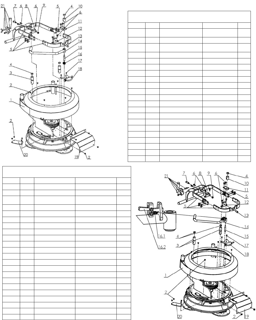
2. LAVINA®30G‐STOPCOVER1PARTS
/FORMACHINESPRODUCEDBEFOREJAN.12014/
Model No. Item No. Description Pcs.
L30G-S 1 L25GS-19.00.00 Top Cover
Assembly 1
L30G-S 2 M6X10ISO7380F Screw 14
L30G-S 3 L25NSPS-07.00.00.05 Back Weight
Holder 2
L30G-S 4 L25SPS-07.00.00.29 Rubber Buffer 3
L30G-S 5 L25GS-18.00.00 Frame Assembly 1
L30G-S 6 M8X20DIN6921 Bolt 8
L30G-S 7 L25GS-10.00.31 Pin Back 1
L30G-S 8 L25GS-15.00.03 Support Back 1
L30G-S 9 M10DIN982 Nut 1
L30G-S 10 L25NP-07.00.00.10 Cup 1
L30G-S 11 L25GS-15.00.04 Support Top 1
L30G-S 12 L25GS-15.00.02 Support Front 1
L30G-S 13 L25GS-10.00.30 Pin Front 1
L30G-S 14 L25GS-15.02.00 Bar 1
L30G-S 15 L25SPS-07.00.00.26 Stud 1
L30G-S 16 L25SPS-07.00.00.25 Spring 1
L30G-S 17 M5X12DIN6921 Bolt 2
L30G-S 18 A29.10.00 Spray Unit 1
L30G-S 19 L25G-10.00.69 Front Guard 1
L30G-S 20 L25S-15.00.23 Inspection Cover 1
L30G-S 21 L25GS-18.30.00 Clamp head 1
2.LAVINA®30G‐STOPCOVER1PARTS
/FORMACHINESPRODUCEDAFTERJAN.12014/
Model No. Item No. Description Pcs.
L30G-S 1 L25GS-19.00.00 Top Cover Assembly 1
L30G-S 2 M6X10ISO7380F Screw 14
L30G-S 3 L25NSPS-
07.00.00.05 Back Weight Holder 2
L30G-S 4 L25SPS-07.00.00.29 Rubber Buffer 3
L30G-S 5 L25GS-18.00.00 Frame Assembly 1
L30G-S 6 M8X20DIN6921 Bolt 8
L30G-S 7 L25GS-10.00.31 Pin 1
L30G-S 8 L25GS-15.00.03 Support Back 1
L30G-S 9 M10DIN982 Nut 1
L30G-S 10 L25NP-07.00.00.10 Cup 1
L30G-S 11 L25S-15.00.04 Support Top L25-S 1
L30G-S 12 L25GS-15.00.02 Support Front 1
L30G-S 13 L25GS-10.00.30 Pin 1
L30G-S 14 L25S-15.10.00 Bar Assembly L25-S 1
L30G-S 15 L25SPS-07.00.00.26 Stud 1
L30G-S 16.1 L25S-15.10.03 Spring L25-S 1
L30G-S 16.2 L25S-15.10.02 Lever 1
L30G-S 17 M5X12DIN6921 Bolt 2
L30G-S 18 A29.10.00 Spray Unit 1
L30G-S 19 L25G-10.00.69 Front Guard 1
L30G-S 20 L25S-15.00.23 Inspection Cover 1
L30G-S 21 L25GS-18.30.00 Clamp head 1
Superabrasive UserManual OriginalLanguageLavina®30G‐S 8/2014
30
*WhiledismountingtheclutchuseoneClutchWasherwithitemNoL25G‐S‐10.02.06,insteadofpreviouslymountedtwo
WasherswithitemNoW1220.
3.LAVINA®30G‐SENGINEBASEPARTS
Model No. Item No. Description Pcs.
L30G-S 1 FS481VA-CS10-M Kawasaki Engine 1
*L30G-S 2 L25GS-10.02.06 Clutch Washer 1
L30G-S 3 5215 Electric Clutch 1
L30G-S 4 L25G-10.02.02.S Bolt Set 1
L30G-S 5 M8X25DIN933 Bolt 4
L30G-S 6 M8DIN127B Spring Washer 9
L30G-S 7 M8DIN125A Washer 6
L30G-S 8 L25G-10.00.65 Engine Base Plate 1
L30G-S 9 F33008 Washer 4
L30G-S 10 F33622 Washer 4
L30G-S 11 F13107 Bolt 4
L30G-S 12 L25G-10.00.66 Tensioning Device
Support 1
L30G-S 13 M8X25DIN912 Screw 2
L30G-S 14 M8X40DIN933 Bolt 1
L30G-S 15 M6X10ISO7380F Screw 4
L30G-S 16 L25G-10.05.00 Back Guard 1
L30G-S 17 OMEGAHP7608MHP30
Endless Transmission
Belt 1
L30G-S 18 M6DIN9021A Washer 2
L30G-S 19 M6DIN127B Washer 1
L30G-S 20 M6DIN934 Nut 1
L30G-S 21 L25G-10.00.67-01 Support 1
L30G-S 22 M6X20DIN933 Bolt 1
L30G-S 23 M8X20DIN933 Bolt 2
4.LAVINA®30G‐STOPCOVER2PARTS
No. Item No. Description Pcs.
L30G-S 1 L25GS-19.00.01 Top Cover 1
L30G-S 2 L25GS-19.10.00 Vacuum Port 1
L30G-S 3 L25GS-19.20.00 Water Fitting 1
L30G-S 4 M12DIN985 Nut 1
L30G-S 5 M5DIN125A Washer 4
L30G-S 6 M5DIN127B Spring Washer 4
L30G-S 7 M5DIN934 Nut 4
L30G-S 8 L25SPS-04.01.00.00 Vacuum Port 1
L30G-S 9 M5X16DIN84A Screw 3
Superabrasive UserManual OriginalLanguageLavina®30G‐S 8/2014
31
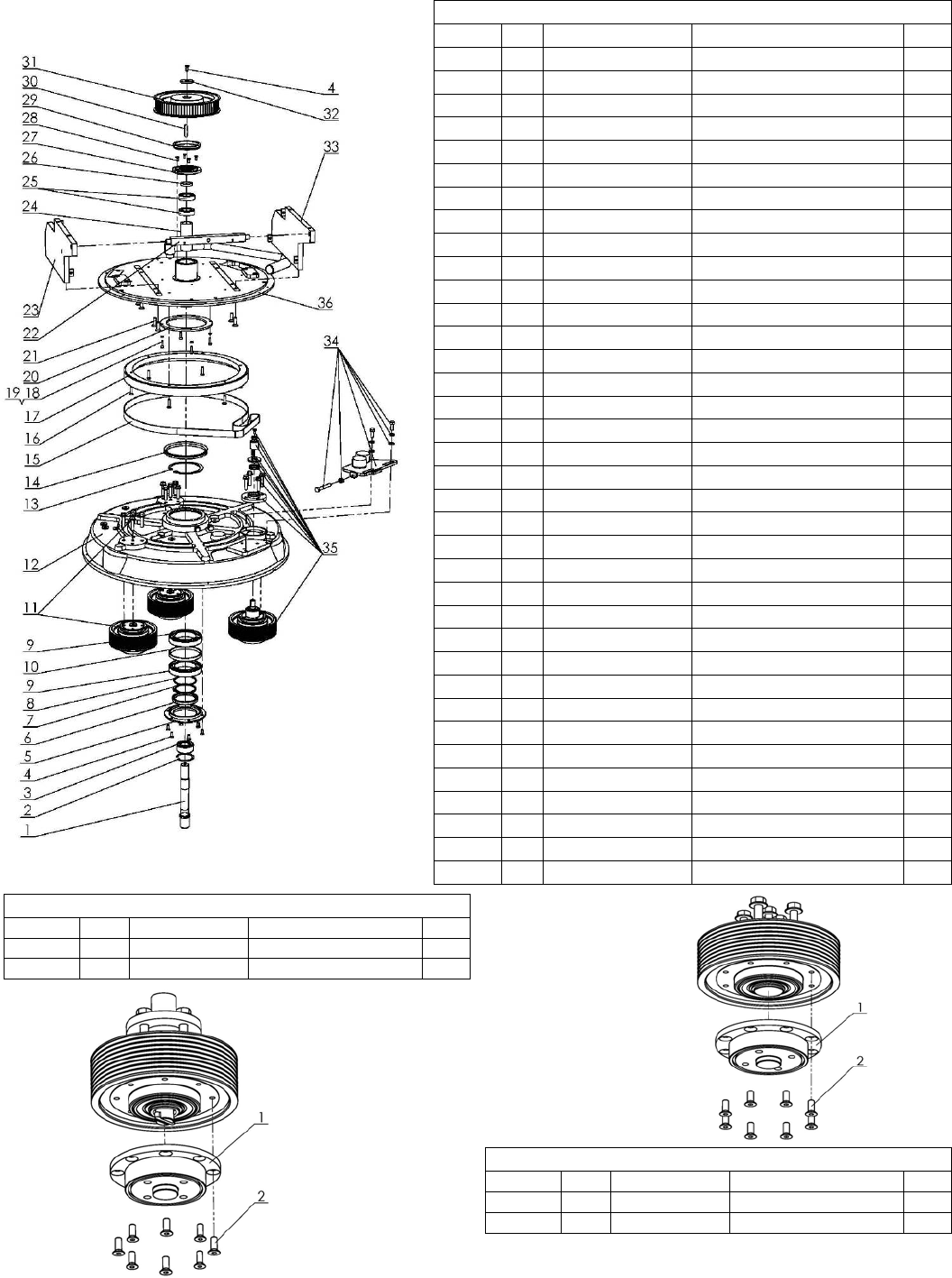
5.LAVINA®30G‐SPLANETARYDRIVEPARTS
Model No. Item No. Description Pcs.
L30G-S 1 L25G-10.00.57 Shaft 1
L30G-S 2 A52 DIN472 Retaining Ring 1
L30G-S 3 3205 Roller Assembly 1
L30G-S 4 M6X16DIN7991 Screw 7
L30G-S 5 L25L-10.00.21 Cap 1
L30G-S 6 TRA000650 Rotary Seal 1
L30G-S 7 B65DIN471 Retaining Ring 1
L30G-S 8 L25SPS-00.00.00.23 Compensating Ring 1
L30G-S 9 6013 Roller Assembly 2
L30G-S 10 L25SPS-00.00.00.34 Distance Ring 1
L30G-S 11 L25LS-11.00.00 Pulley Unit Assembly 2
L30G-S 12 L25LS-10.00.06 Disc 1
L30G-S 13 A10013943 Retaining Ring 1
L30G-S 14 TWVA01200 V-Ring Type A 1
L30G-S 15 TC-20EF1500X20X2 Endless Transmission Flat Belt 1
L30G-S 16 M6X25DIN7991 Screw 6
L30G-S 17 L25S-15.00.22 Planetary Pulley 1
L30G-S 18 M5DIN7980 Spring Washer 4
L30G-S 19 M5X16DIN912 Screw 4
L30G-S 20 L25P-01.03.00.09 Flange 1
L30G-S 21 M8X25DIN7991 Screw 8
L30G-S 22 L25G-10.00.64 Support Plate 1
L30G-S 23 L25GS-10.03.00 Left Plate Assembly 1
L30G-S 24 L25G-10.00.58 Bushing 1
L30G-S 25 6005 Roller Assembly 2
L30G-S 26 L25G-10.00.59 Insert 1
L30G-S 27 L25G-10.00.60 Cap for Rotary Seal 1
L30G-S 28 M5X12DIN7991 Screw 4
L30G-S 29 TWVA00700 V-Ring Type A 1
L30G-S 30 DIN6885A8X7X36 Key 1
L30G-S 31 L25G-10.00.61 Pulley Unit 1
L30G-S 32 L25SPS-00.00.00.15 Front Washer 1
L30G-S 33 L25GS-10.04.00 Right Plate Assembly 1
L30G-S 34 L25S-17.00.00 Planetary Tensioning Unit 1
L30G-S 35 L25LS-16.00.00 Driving Pulley Unit 1
L30G-S 36 L25GS-15.01.00 Base plate 1
5a.LAVINA®30G‐S PULLEY UNIT ASSEMBLY
Model No. Item No. Description Pcs.
L30G-S 1 L25LS-16.00.03 Flange 1
L30G-S 2 M6X16DIN7991 Screw 8
5b.LAVINA®30G‐S DRIVING PULLEY UNIT
Model No. Item No. Description Pcs.
L30G-S 1 L25LS-16.00.03 Flange 1
L30G-S 2 M6X16DIN7991 Screw 8
Superabrasive UserManual OriginalLanguageLavina®30G‐S 8/2014
32
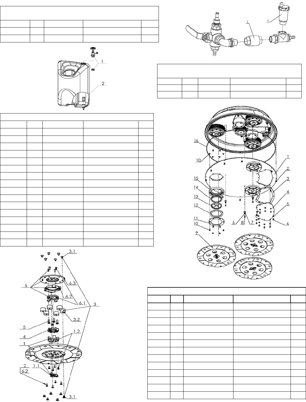
6.LAVINA®30G‐SWATERSUPPLYPARTS
/FORMACHINESPRODUCEDBEFOREJAN.12014/
Model No. Item No. Description Pcs.
L30G-S 1 A29.21.00 Backflow Preventer 1
L30G-S 2 A29.22.00 Vent Valve 1
6. LAVINA®30G‐SWATERTANKPARTS
/FORMACHINESPRODUCEDAFTERJAN.12014/
Model No. Item No. Description Pcs.
L30G-S 1 A29.50.00 Regulator 1
L30G-S 2 1/2" Filter 1
7.LAVINA®30G‐SBOTTOMCOVER1PARTS
Model No. Item No. Description Pcs.
L30G-S 1 L25LS-14.00.00 Bottom Cover Assembly 1
L30G-S 2 M5X12DIN6921 Bolt 12
L30G-S 3 L25LS-14.00.05 Sealer Inspection Cover 1
L30G-S 4 L25L-10.00.09 Inspection Cover 1
L30G-S 5 M6DIN127B Spring Washer 13
L30G-S 6 M6X12DIN933 Bolt 10
L30G-S 7 M6DIN9021A Washer 3
L30G-S 8 M6X16DIN933 Bolt 3
L30G-S 9 A35.00.00 Tool Holder A35 3
L30G-S 10 M6X10DIN7991 Screw 36
L30G-S 11 L25LS-14.00.03 Outer Cover 3
L30G-S 12 110X90X8.5 Felt Ring 3
L30G-S 13 A37.00.01 Adaptor 3
L30G-S 14 TWVA00800 V-Ring Type A 3
L30G-S 15 L25LS-14.00.02 Flange 3
L30G-S 16 D4X2X1880 Seal 1
8.LAVINA®30G‐STOOLHOLDERPARTS
Model No. Item No. Description Pcs.
L30G-S 1 A35.10.00 Quick Change Assembly 1
L30G-S 1.1 A31.12.00 Keylock Set 1
L30G-S 1.2 A31.10.02-K Copling 2 with screws 1
L30G-S 2 M6X16DIN7991 Screw 4
L30G-S 3 A25.00.10-K Buffer with two screw 6
L30G-S 3.1 M8X12DIN7991 Screw 12
L30G-S 3.2 A25.00.10 Buffer 6
L30G-S 4 A25.00.05-02 Spider 1
L30G-S 5 M8X25DIN7991-10.9 Screw 4
L30G-S 6 A31.20.00 Flange 1
L30G-S 6.1 A31.20.03-K Copling 1 with screws 1
L30G-S 6.2 A31.20.02-K Security ring 1
L30G-S 6.3 A31.20.01 Flange A31 1
Superabrasive UserManual OriginalLanguageLavina®30G‐S 8/2014
33
9.LAVINA®30G‐SBOTTOMCOVER2PARTS
Model No. Item No. Description Pcs. No. Item No. Description Pcs.
L30G-S 1 L25L-12.00.00 Tensioning Support 1 13 L25L-10.00.12 Sector 1
L30G-S 2 L25L-10.00.16 Sector 1 14 L25L-10.00.07 Support 2
L30G-S 3 M6DIN127B Spring Washer 1 15 L32C.14.20.04 Nut 1
L30G-S 4 M6X30DIN933 Bolt 1 16 M10DIN934 Nut 2
L30G-S 5 PL2476-975L-9 Endless Transmission V Belt 1 17 L25L-10.00.08 Washer 2
L30G-S 6 L25G-10.00.17 Central Pulley 1 18 L25L-10.00.13 Sector 1
L30G-S 7 L25SPS-00.00.00.15 Front Washer 1 19 L25L-10.00.11 Sector 1
L30G-S 8 M6X16DIN7991 Screw 1 20 L25L-10.00.15 Sector 1
L30G-S 9 DIN6885A8X7X36 Key 1 21 L25L-10.00.19 Distance Bolt 3
L30G-S 10 M8DIN127B Spring Washer 11 22 D6X2 O-Ring 3
L30G-S 11 M8DIN934 Nut 11 23 L25L-13.00.00 Deflection Pulley 1
L30G-S 12 L25L-10.00.14 Sector 1
10.LAVINA®30G‐SCONTROLBOARDPARTS
Model No. Item No. Description Pcs.
L30G-S 1 W1301 Start/Stop Switch 1
L30G-S 2 W1330 Clutch Switch 1
L30G-S 3 W4110 Throttle 1
L30G-S 4 W4313 Hour Meter 1
L30G-S 5 6х30/30А Fuse 1
L30G-S 6 W9999 Pump switch 1
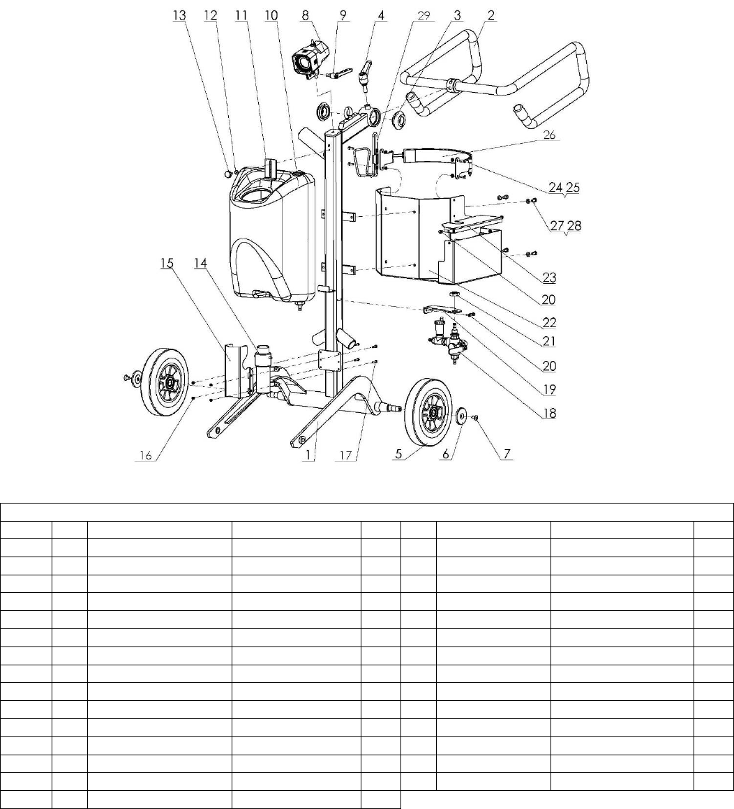
Superabrasive UserManual OriginalLanguageLavina®30G‐S 8/2014
34
11.LAVINA®30G‐SCARRIAGEPARTS/FORMACHINESPRODUCEDBEFOREJAN.12014/
Model No. Item No. Description Pcs. No. Item No. Description Pcs.
L30G-S 1 L25GS-21.00.00 Frame 1 16 M5DIN985 Nut 4
L30G-S 2 L25G-23.00.00 Handle Assembly 1 17 M5X20DIN933 Bolt 4
L30G-S 3 L25SPS-02.00.00.18-01 Nut 2 18 A29.20.00 Water Flow Control Unit 1
L30G-S 4 A58194 Swivel Bolt 1 19 A29.20.01-01 Flow Unit Base 1
L30G-S 5 L25G-20.00.04 Wheel 2 20 M5X12DIN6921 Bolt 4
L30G-S 6 L32D-20.00.03 Wheel Cap 2 21 M20X1.5DIN439B Nut 1
L30G-S 7 M10X16DIN7991 Screw 2 22 L25G-22.00.00 Propane Tank Holder 1
L30G-S 8 L20NS-30.30.00 Lamp Unit Incl. Cable 1 23 L25G-20.00.05 Battery Cover 1
L30G-S 9 A58165 Swivel Bolt 1 24 M6X16DIN933 Bolt 4
L30G-S 10 A33.00.00 Tank 1 25 M6DIN985 Nut 4
L30G-S 11 L25P-02.00.00.01 Top Bracket 1 26 L25GS-25.00.00 Strap 1
L30G-S 12 M5UN732 Washer 1 27 M8DIN125A Washer 4
L30G-S 13 T34391 Knob Bolt 1 28 M8X16DIN933 Bolt 4
L30G-S 14 1040 Water Pump 1 29 Cup Holder 1
L30G-S 15 L25S-20.00.26 Guard 1
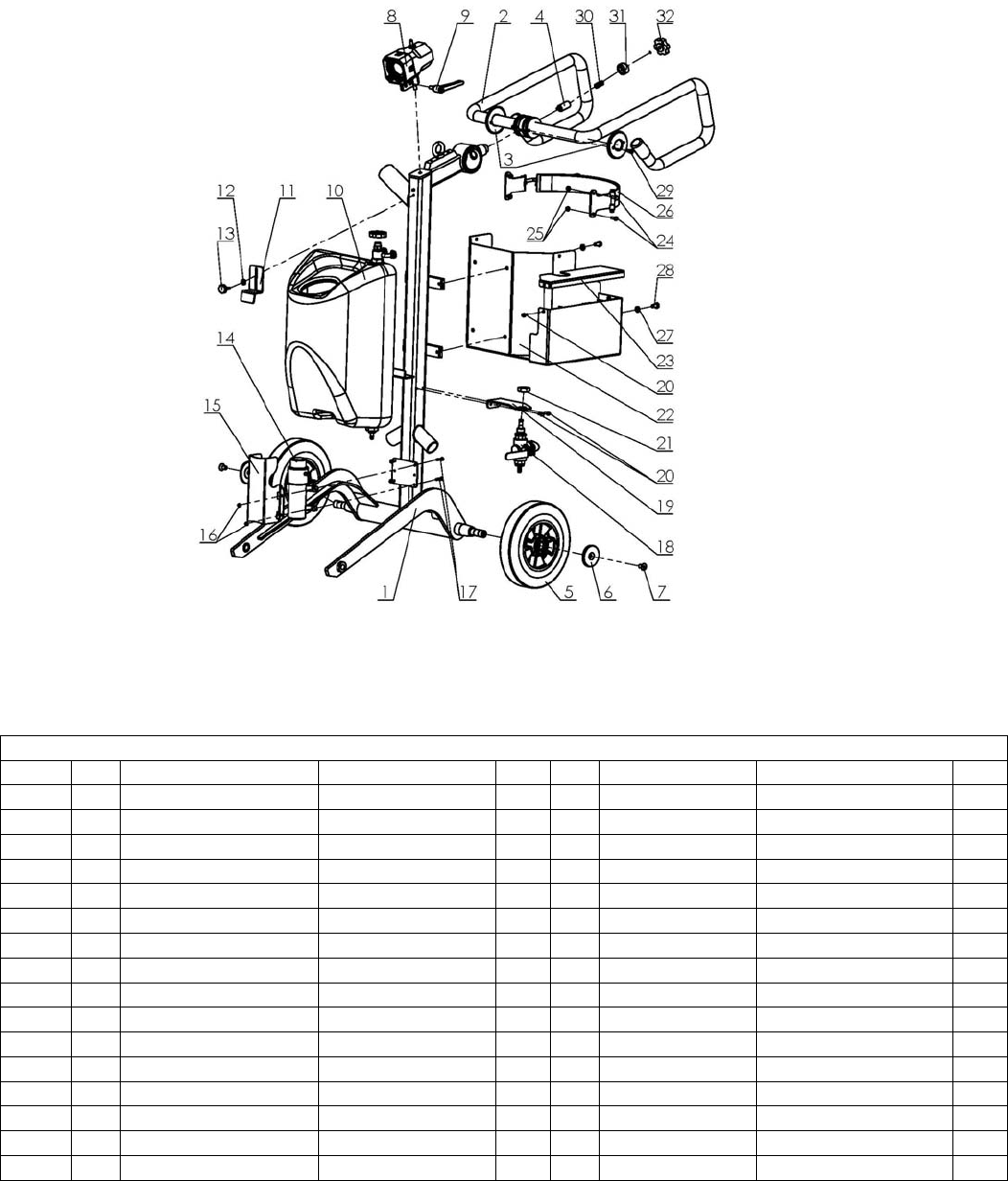
Superabrasive UserManual OriginalLanguageLavina®30G‐S 8/2014
35
11.LAVINA®30G‐SCARRIAGEPARTS/FORMACHINESPRODUCEDAFTERJAN.12014/
Model No. Item No. Description Pcs. No. Item No. Description Pcs.
L30G-S 1 L25GS-21.00.00-01 Frame 1 17 M5X20DIN933 Bolt 4
L30G-S 2 L25S-23.10.00 Handle Assembly 1 18 A29.40.00 Water Flow Control Unit 1
L30G-S 3 L25S-23.00.02 End Cover 2 19 A29.20.01-01 Flow Unit Base 1
L30G-S 4 L25S-23.00.06 Locking bit 1 20 M5X12DIN6921 Bolt 4
L30G-S 5 L25G-20.00.04 Wheel 2 21 M20X1.5DIN439B Nut 1
L30G-S 6 L32D-20.00.03 Wheel Cap 2 22 L25G-22.00.00 Propane Tank Holder 1
L30G-S 7 M10X16DIN7991 Screw 2 23 L25G-20.00.05 Battery Cover 1
L30G-S 8 L20NS-30.30.00 Lamp Unit Incl. Cable 1 24 M6X16DIN933 Bolt 4
L30G-S 9 A58165 Swivel Bolt 1 25 M6DIN985 Nut 4
L30G-S 10 A33.10.00 Tank Assembly 1 26 L25GS-25.00.00 Strap 1
L30G-S 11 L25P-02.00.00.01 Top Bracket 1 27 M8DIN125A Washer 4
L30G-S 12 M5UN732 Washer 1 28 M8X16DIN933 Bolt 4
L30G-S 13 T34391 Knob Bolt 1 29 M6X12DIN912 Screw 4
L30G-S 14 1040 Water Pump 1 30 L25S-23.00.07 Spring L25-S 1
L30G-S 15 L25S-20.00.26 Guard 1 31 L25S-23.00.09 Nut 1
L30G-S 16 M5DIN985 Nut 4 32 F17840.TM08x40 Knob Bolt 1
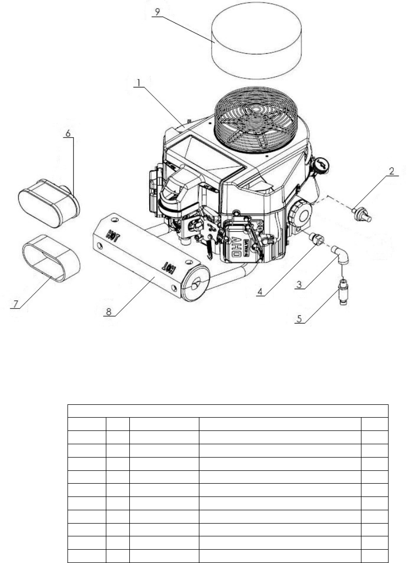
Superabrasive UserManual OriginalLanguageLavina®30G‐S 8/2014
36
12.LAVINA®30G‐SENGINEPARTS
Model No. Item No. Description Pcs.
L30G-S 1 W3132 Kawasaki FS481V-AS10-M 18H 12V 1
L30G-S K49065-7007 Oil Filter 12
L30G-S 2 W1325 Oil Pressure Switch 6
L30G-S 3 F466230 Elbow 1
L30G-S 4 K59071-7004 Joint 1
L30G-S 5 FE17409029909 Oil Drain Valve 1
L30G-S 6 K11013-7049 Element Air Filter 1
L30G-S 7 K11013-7046 Element Air Filter/ Fs481v (Foampre-Filter) 1
L30G-S 8 W3241A Cat Muffler Assy. 1
L30G-S 9 W3305 Kawasaki Bonnet Filter 1
