Guideline Geo 160MHZHDR Ground Penetrating Radar User Manual
Mala GeoScience AB (publ) Ground Penetrating Radar
UserManual.wiki
>
Guideline Geo
>
160MHZHDR User Manual
User manual
Navigation menu
Upload a User Manual
Namespaces
Wiki Guide
HTML
PDF
Info
Views
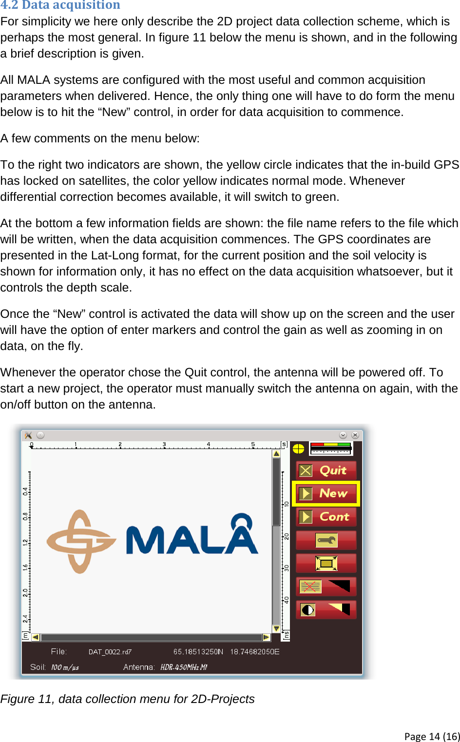
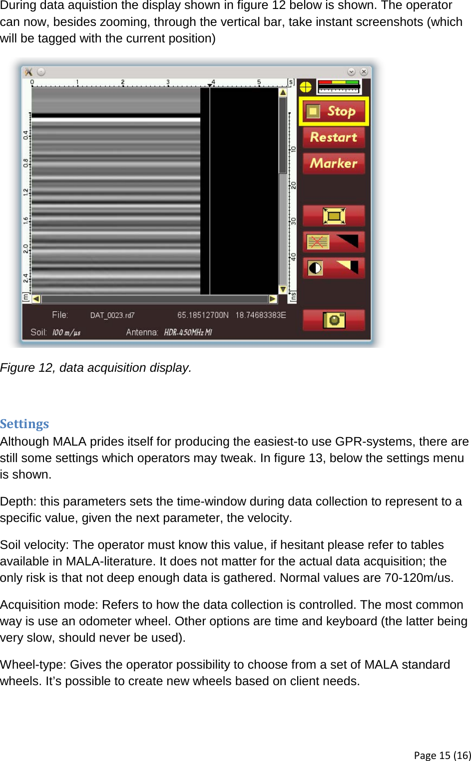
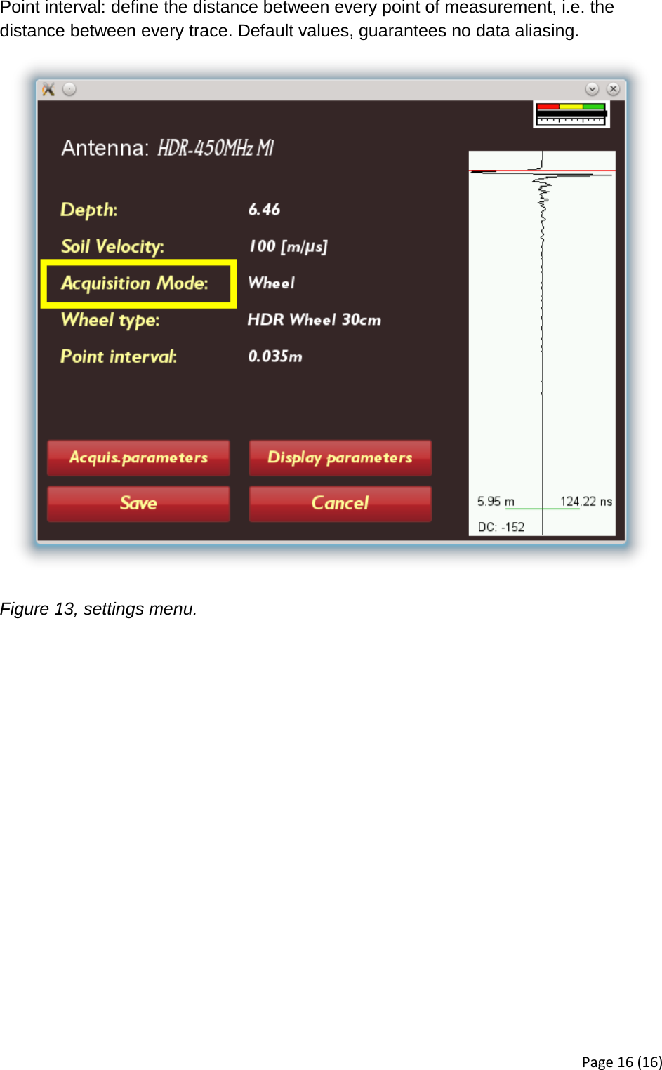
User Manual
Discussion / Help
Navigation