Guideline Geo 80MHZHDR Ground Penetrating Radar User Manual
Mala GeoScience AB (publ) Ground Penetrating Radar
User manual
USER MANUAL
HDR-SERIES SHIELDED ANTENNAS
80, 160, 450 AND 750MHz
VERSION 1.1
December 2013
Page 1 (16)

Product overview
The HDR-series (High Dynamic Range) is the latest addition to MALA’s versatile
product range. It is, from bottom up, a complete new design, based on patented
cutting edge technology. These new antennas are hence not just an upgrade of
earlier designs; they represent a leap in GPR-technology, not seen in the past 15
years. Due to the internal design, the HDR-antennas are self-contained GPR
systems, so, naming them antennas is somewhat misplaced. Each one of them
actually contains a full-blown GPR system
Compared with earlier, comparable systems, this new suit of GPR-systems is
capable of much faster data acquisition rates, without violation of the FCC, EC and IC
regulatory limits on emissions. Combined with increased bandwidth, this extreme
performance gives the user a system with unprecedented dynamic range and
resolution.
At the end of the day, these products give the GPR community access to easy-to use
systems with significant deeper penetration as well as better detection capabilities.
Add to this the positioning options, software capabilities and proven accessories and
you have in your hands full access to the GPR-future. Never before has the GPR-
market been offered so much value for the money.
Scope
This manual describes the MALA HDR series of shielded antenna. It’s a hardware
manual, intended to give users a fast guide for handling the antenna units in the field.
It’s not a complete system manual. For further information on using the GPR system,
please refer to the software manual for the monitor you have bought with the system.
Page 2 (16)
Content
Product overview ........................................................................................................ 2
Scope ......................................................................................................................... 2
1 Introduction .............................................................................................................. 4
1.1 Unpacking and Inspection ................................................................................. 4
1.2 Repacking and Shipping ................................................................................... 5
1.3 Safety and Compliance, user notices ................................................................ 5
2 External connectors indicators and controls ............................................................ 7
2.1 Battery mount .................................................................................................... 8
2.2 Cables ............................................................................................................... 9
2.3 Important note on cables and near-by metal objects ......................................... 9
2.4 Power ON/OFF .................................................................................................. 9
2.5 LED-indicators ................................................................................................. 10
2.6 Mounting of measuring wheels ........................................................................ 11
3 Accessories ........................................................................................................... 12
3.1 Forest kits ........................................................................................................ 12
4. Software ............................................................................................................... 12
4.1 Projects ........................................................................................................... 13
4.2 Data acquisition ............................................................................................... 14
Settings ................................................................................................................. 15
Page 3 (16)

1 Introduction
Thank you for purchasing the MALA HDR-80/160/450/750 system. We at MALA
GeoScience welcome comments from you concerning the use and experience of this
equipment, as well as the contents and usefulness of this manual. Please take the
time to read through the assembling instructions carefully and address any questions
or suggestions to the following:
MALÅ GeoScience postal address is:
Main Office: Subsidiary:
Malå GeoScience Malå GeoScience USA, Inc. E-Mail: sales@malags.se
Skolgatan 11 P.O. Box 80430 sales.usa@malags.se
S-930 70 Malå Charleston, SC 29416 rental@malags.se
Sweden USA support@malags.se
Phone: +46 953 345 50 Phone: +1-843 852 5021
Fax: +46 953 345 67 Fax: +1-843 769 7397
Information about MALÅ Geoscience’s products is also available on Internet:
www.malags.com
(Be sure to include instrument type and serial numbers)
1.1 Unpacking and Inspection
Great care should be taken when unpacking the equipment. Be sure to verify the
contents shown on the packing list and inspect the equipment for any loose parts or
other damage. All packing material should be preserved in the event that any
damage occurred during shipping. Any claims for shipping damage should be filed to
the carrier. Any claims for missing equipment or parts should be filed with MALA
GeoScience.
Page 4 (16)
1.2 Repacking and Shipping
If original packing materials are unavailable, the equipment should be packed with at
least 80 mm of absorbing material. Do not use shredded fibers, paper wood, or wool,
as these materials tend to get compacted during shipment and permit the instruments
to move around inside the package.
1.3 Safety and Compliance, user notices
This GPR-device is certified according to FCC, subpart 15, IC RSS-220 and ETSI EN
302 066-1&2.
If this device is opened, or in any way tampered with internally, all warranties are
void. Furthermore, if any changes or modifications are done internally, the users
authority to operate the device may be void, in accordance with FCC §15.21.
According to the regulations stated in ETSI EN 302 066-1 (European
Telecommunication Standards Institute):
The control unit should not be left ON when leaving the system unintended. It should
always be turned OFF when not in use.
The antennas should point towards the ground, walls etc. during measurement and
not towards the air.
The antennas should be kept in close proximity to the media under investigation.
Canadian and US regulations states that whenever GPR-antennas are in
use the following notes apply:
This Ground penetrating Radar device shall be operated only when in contact with or
within 1 m of the ground.
This Ground Penetrating Radar Device shall be used only by law enforcement
agencies, scientific research institutes, commercial mining companies, construction
companies and emergency rescue or firefighting organizations.
This device complies with Industry Canada license-exempt RSS standards.
Operation is subject to the following two conditions: (1) This device may not cause
interference and (2) this device must accept any interference, including interference
that may cause undesired operation of the device.
French translations:
Cet instrument de Géoradar se devra d’être opéré seulement en contact à même le
sol ou en deça d’un mètre du sol.
Cet instrument de Géoradar se devra d’être utilisé seulement par les agences
chargées de l’application de la loi, les instituts de recherches scientifiques, les
Page 5 (16)
compagnies minières à buts lucratifs, les compagnies de construction et les
organisations responsables pour le sauvetage et la lutte contre les incendies.
Cet instrument répond aux exigences de la licence avec Industrie Canada- exempt
des standards RSS. L ‘opération est sujette aux deux conditions suivantes : (1) Cet
instrument ne peut pas causer une interférence et (2) cet instrument se doit
d’accepter quelque interférence que ce soit, incluant une interférence qui pourrait
causer une opération non-souhaitable de l’instrument.
Page 6 (16)
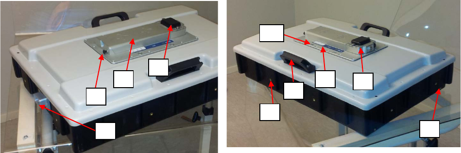
2 External connectors indicators and controls
In figure 1, below, pictures of the HDR-160MHz are shown. All antennas in this series
have the same basic layout, only that for the 750MHz, no-side handles are available.
In the following a brief description of the unit is given, with reference to arrows and
labels in figure
1. GPS. The black plastic on top of the connector tower hoses the in-build
differential GPS-receiver and antenna. This receiver has in-built SBAS-
correction capabilities. It is essential that the antenna is mounted in a such a
way to give the GPS antenna as much of free sky as possible
2. Battery. The LI-Ion batteries are housed in a casing of worked aluminum, and
have a nominal capacity of 7.8 Ah, 11.1V. This gives at least 5 hours of
operation, somewhat varying between the different models.
3. Battery release knob. The batteries are held in place by a spring loaded pin, in
order to release/mount the battery, the knob is pulled.
4. Measuring wheel mount. The measuring wheel is mounted via a protected,
waterproof 9-oin d-sub connector. The wheel is locked in place by a vertical
pin, see later section.
5. Mounting inserts. The units have 2 inserts, M6-threads, on each side, these
are intended for mounting purposes, either mounting the antenna in a custom-
designed carrier or for carrying purposes.
6. Carrying handles. By default the 3 lower frequencies have handles mounted
on the perimeter of the units. These are intended for tunnel wall, rock-wall
applications as well as for pure transportation handles.
7. Product label and LED-indicators see later sections.
8. Connection tower. Power, communications as well as on/off button is mounted
in a casing of worked aluminum on top of the unit; this casing also contains the
GPS unit and antenna, if this option is installed. Note the connection tower is
not intended to be removed at any time, waterproofness of the unit cannot be
warranted if this part is removed.
9. Inserts for wear-plate. Two inserts, back and front, are intended for fastening
of wear plates, M4-threads.
10. Mounting inserts. Additional inserts, M6-threads, are mounted on the top
metal plate, by means of insert-rivets.
Figure 1, pictures from back (left), and front (right) of the HDR-160MHz antenna,
arrows and labels refer to items explained in the text above.
1
2
3
4
5
6
7
8
9
10
Page 7 (16)
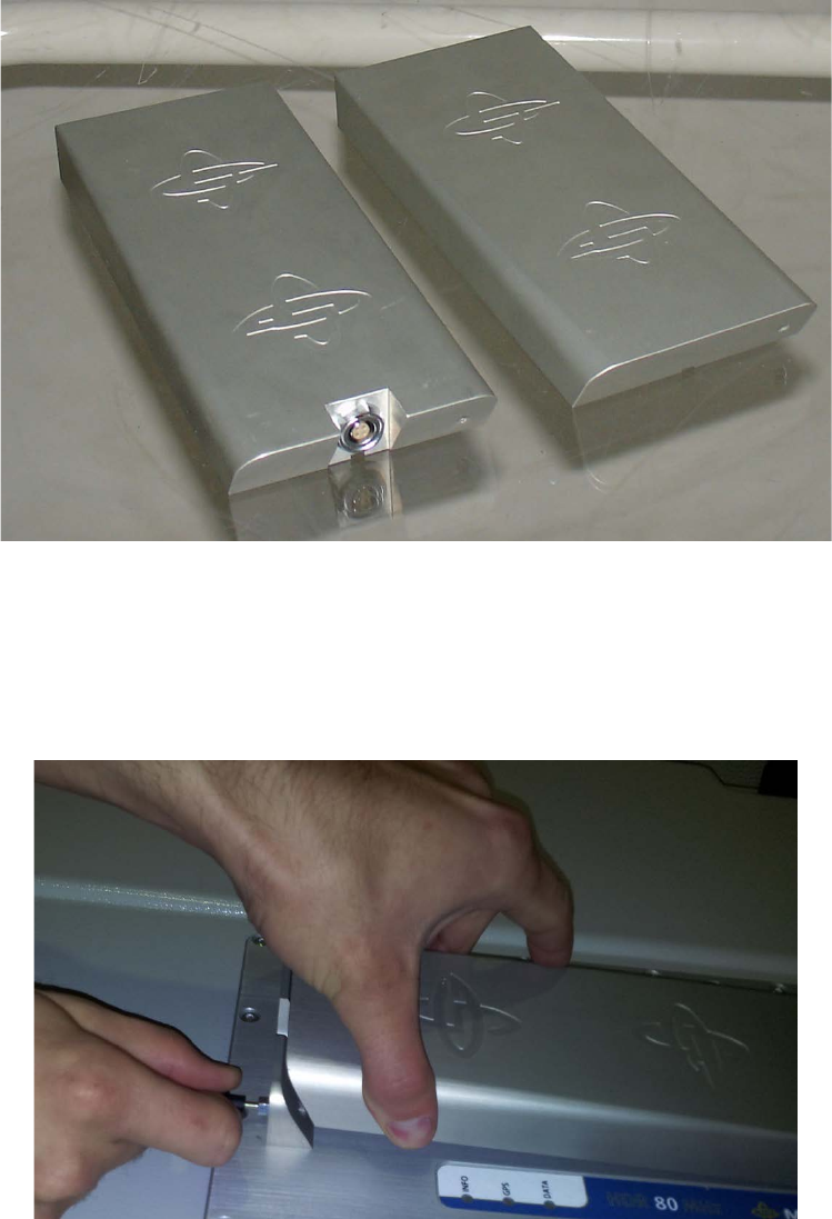
2.1 Battery mount
In figure 2, below, a dummy battery as well as a normal battery is shown. They look
similar but the dummy has a 4-pole fisher connector on the back. The dummy is used
when the antenna is powered from an external 12V battery.
Both of these units are mounted in the same way on the antenna, see below.
Figure 2, dummy-battery and normal LI-Ion battery.
When mounting the battery, gently attach the d-sub connector in front of the battery
with the d-sub on the mounting tower. Then pull the battery-relief know and press
down the battery in place. By releasing the knob, the battery is secured in place, see
figure 3, below.
Figure 3, mounting and dismounting the battery.
Page 8 (16)
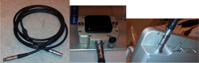
2.2 Cables
The only cable needed, is the communication cable between the antenna and the
monitor. See figure 4 below. The cable is a high-quality design with field-rugged
ODU-connectors. It may be ordered in different lengths, at some extra cost.
Figure 4, Left cable for communication between the monitor and HDR-unit. Cable
connected to the HDR-unit and (right) cable connected to the monitor.
If external batteries are to be used, special cables have to be ordered as well as the
dummy-battery.
2.3 Important note on cables and near-by metal objects
The HDR-suit of GPR-systems represents an unprecedented leap in technology.
Each one of the units is a high-tech precision instrument and most of them are
capable of digitizing to more than 16-bits.
This means that the mounting and cabling used with the units become much more
critical than for previous systems. All experienced GPR users knows the importance
of keeping your cables tidily mounted, this is now much more important, because the
sensitivity of these units are much higher.
For this reason all MALA cables have ferrites attached to them as well as
recommended routing. If you experience some ring-down, please first check your
cable mounting, it has been the main cause of internal complaints, previous
acceptable routings are no longer valid.
2.4 Power ON/OFF
The units are powered on by a gentle push on the button mounted on the front of the
connection tower, see figure 5 below. A weak “click” will be heard when the internal
relay switches the power on. The ON-button internal LED will show a steady red light
and the LED-indicators will come alive, see later section.
Power off is managed in two ways; 1) by leaving the data acquisition software in the
monitor, and 2) by holding the on/off switch for approximately 3 seconds and then
releasing it.
Page 9 (16)
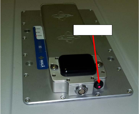
Figure 6, ON/OFF-Switch
2.5 LED-indicators
Three LED-indicators are mounted beneath the product label, see figure 7 below.
The meaning of these indicators is as follows:
DATA: Continuous flashing light means that the unit is working properly and ready for
data collection, no proof of that a monitor is able to receive data, though. If irregular
flashing is seen on this LED, it means erroneous antenna configuration, possible
software version issue. This LED is switching to continuous light when the unit enters
data collection.
GPS: Flashing light mean that the GPS option is installed and that the internal
computers are successfully communicating with the GPS-unit. This LED-switch to
continuous light whenever there’s 4 or more satellites available. Nothing is told about
whether differential correction is active, the latter information is shown in the monitor.
INFO: This LED indicates a serious system Error, whenever active. Please contact
your local distributor.
ON/OFF-Switch
Page 10 (16)
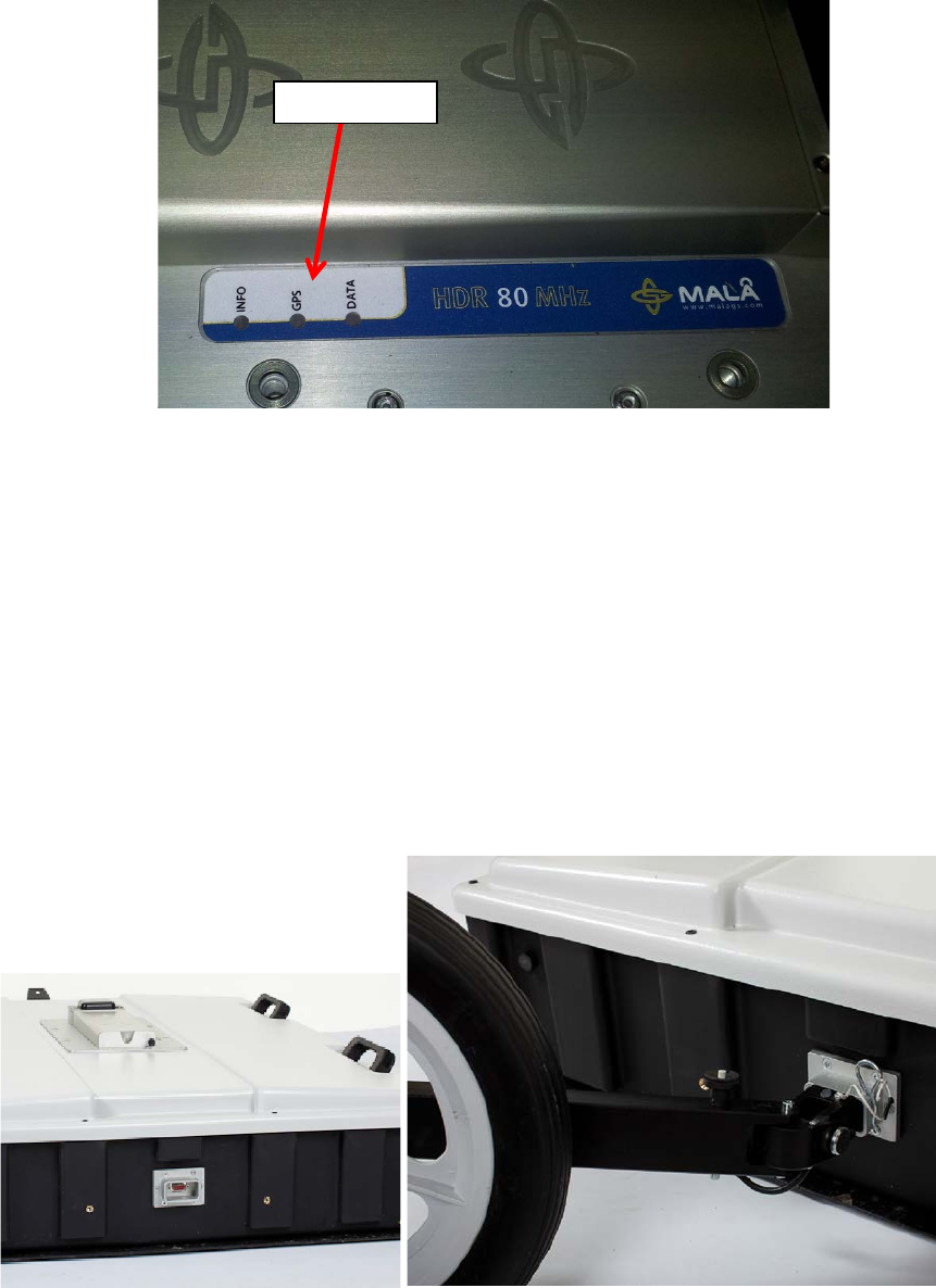
Figure 7, led indicators.
2.6 Mounting of measuring wheels
The several measuring wheels are available for the HDR-units. Each one of them has
been designed to fit to the field-proven ruggedized connector housing on the back of
the antennas.
To connect a wheel, gently push the wheel connector into the connector housing and
attach the secure-pin.
Figure 8, mounting of measruring wheels.
LED-Indicators
Page 11 (16)
3 Accessories
The HDR-suit has a number of accessories, including, but not limited to: Cart’s,
measuring wheels; road-carts, pulling handles, forest kits, and wear plates. In
addition, there’s cables, battery chargers, shipping cases etc. etc. In the following just
a few of these are described.
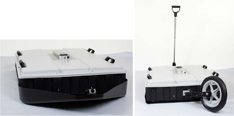
3.1 Forest kits
Whenever GPR surveys needs to be done in rough terrain, a suitable mounting of the
antenna is needed. The antenna units are quite squarely designed, meaning that
they will stick to threes, boulders and whatever obstacles are passed. To mitigate this
inconvenience we have designed the forest kits. They consist of a ski-formed wear-
plate with a fastener in front, see figure 8 below. The design is such that the
mounting plate in front will break, prior to the antenna housing, an important feature,
if a 4-wheeler is in use.
Figure 9, a HDR-80MHz mounted in a forest kit, with measureing wheel attached.
4. Software
The HDR-antennas can only be operated with MALA XV-monitors; no windows PC
software is available. Although a description of the acquisition software is outside the
scope of this manual, a brief introduction is give below.
Page 12 (16)
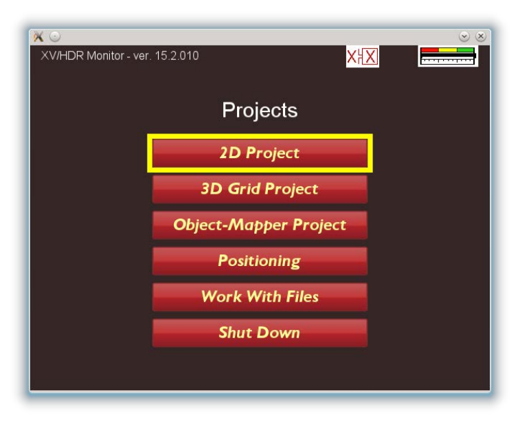
4.1 Projects
In order to streamline the data acquisition and provide a user interface optimized in
terms of user friendliness, MALA provides application specific data acquisition
schemes. In figure 10, below, the first screen (after the start-up info) is shown. The
user has the options to choose between:
2D-project: a general, single line data acquisition scheme, the traditional way of
gathering GPR-data.
3D-Grid Project: A data question whereby the user is guided in collection of data in
a grid, suitable for MALA-2.5D visualization and interpretation.
Object-Mapper-Project: The MALA-proprietary model of mapping areas, marking
objects in the data and producing client reports, with just a few clicks.
Besides these three data acquisition schemes the client have some extra options in
using the GPR as a positioning and revieing previously collected data.
On the top line, the software version, a symbol showing connection status with the
antenna and a battery indicator is shown. In this case no data acquisition is possible
since no antenna is attached, indicated by a red X.
Note that whenever the option “Shut Down” is chosen, the antenna will be powered
off, if it’s attached and switched on.
Figure 10, the first screen after booth up screen.
Page 13 (16)
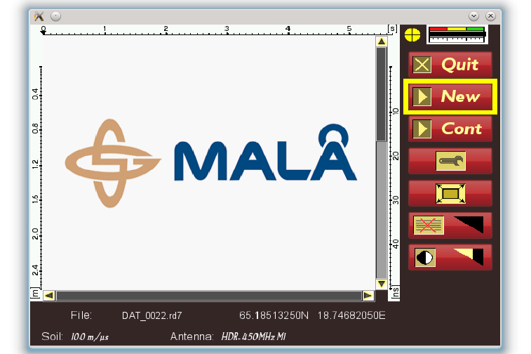
4.2 Data acquisition
For simplicity we here only describe the 2D project data collection scheme, which is
perhaps the most general. In figure 11 below the menu is shown, and in the following
a brief description is given.
All MALA systems are configured with the most useful and common acquisition
parameters when delivered. Hence, the only thing one will have to do form the menu
below is to hit the “New” control, in order for data acquisition to commence.
A few comments on the menu below:
To the right two indicators are shown, the yellow circle indicates that the in-build GPS
has locked on satellites, the color yellow indicates normal mode. Whenever
differential correction becomes available, it will switch to green.
At the bottom a few information fields are shown: the file name refers to the file which
will be written, when the data acquisition commences. The GPS coordinates are
presented in the Lat-Long format, for the current position and the soil velocity is
shown for information only, it has no effect on the data acquisition whatsoever, but it
controls the depth scale.
Once the “New” control is activated the data will show up on the screen and the user
will have the option of enter markers and control the gain as well as zooming in on
data, on the fly.
Whenever the operator chose the Quit control, the antenna will be powered off. To
start a new project, the operator must manually switch the antenna on again, with the
on/off button on the antenna.
Figure 11, data collection menu for 2D-Projects
Page 14 (16)
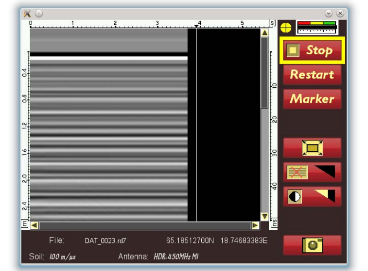
During data aquistion the display shown in figure 12 below is shown. The operator
can now, besides zooming, through the vertical bar, take instant screenshots (which
will be tagged with the current position)
Figure 12, data acquisition display.
Settings
Although MALA prides itself for producing the easiest-to use GPR-systems, there are
still some settings which operators may tweak. In figure 13, below the settings menu
is shown.
Depth: this parameters sets the time-window during data collection to represent to a
specific value, given the next parameter, the velocity.
Soil velocity: The operator must know this value, if hesitant please refer to tables
available in MALA-literature. It does not matter for the actual data acquisition; the
only risk is that not deep enough data is gathered. Normal values are 70-120m/us.
Acquisition mode: Refers to how the data collection is controlled. The most common
way is use an odometer wheel. Other options are time and keyboard (the latter being
very slow, should never be used).
Wheel-type: Gives the operator possibility to choose from a set of MALA standard
wheels. It’s possible to create new wheels based on client needs.
Page 15 (16)

Point interval: define the distance between every point of measurement, i.e. the
distance between every trace. Default values, guarantees no data aliasing.
Figure 13, settings menu.
Page 16 (16)