Guideline Geo SH1GHZ GPR User Manual CUII Manual A5
Mala GeoScience AB (publ) GPR CUII Manual A5
User manual
RAMAC/GPR
Operating manual
Version 1.0
www.malags.com
2
Table of Contents
_________________________________________________
1 Introduction 4
1.1 Unpacking and Inspection 5
1.2 Repacking and Shipping 5
2 General 6
2.1 General description of the GPR Technique 6
2.2 Basic information in investigation depths and velocities 8
3 Radar Control Unit CUII 11
4 Unshielded antennas 14
4.1 Antenna electronics 14
4.2 Antenna elements 16
4.3 Operation modes 18
5 Shielded antennas 20
6 1 GHz shielded antenna 24
7 Power supply, Optical fibres and Communication
cables 26
7.1 Power supply 26
7.2 Optical fibres 27
7.3 Communication cable 28
8 Multi-channel modules 30
9 Trigger devices 32
www.malags.com
3
10 Other accessories 34
10.1 Antenna handles 34
10.2 Skid box 35
10.3 Antenna Sled 36
11 Start up of your RAMAC/GPR CUII 38
11.1 Connecting the system components 39
11.2 Running a survey 40
12 Trouble shooting 42
13 How to assemble the RAMAC/GPR Cart 44
www.malags.com
4
1 Introduction
__________________________________________________
Thank you for purchasing the RAMAC/GPR system. We at
Malå GeoScience welcome comments from you concerning
the use and experience of this equipment, as well as the
contents and usefulness of this manual. Please take the time
to read through the assembling instructions carefully and
address any questions or suggestions to the following:
MALÅ GeoScience postal address is:
Main Office: Subsidiary:
Malå GeoScience Malå GeoScience USA, Inc.
Skolgatan 11 2040 Savage Rd, P.O. Box 80430
S-930 70 Malå Charleston, SC 29416
Sweden USA
Phone: +46 953 345 50 Phone: +1-843 852 5021
Fax: +46 953 345 67 Fax: +1-843 769 7397
E-mail: sales@malags.se E-mail: sales.usa@malags.se
Technical support issues can be sent to: support@malags.se
Information about MALÅ GeoSciences products is also
available on Internet: http://www.malags.com
www.malags.com
5
1.1 Unpacking and Inspection
Great care should be taken when unpacking the equipment.
Be sure to verify the contents shown on the packing list and
inspect the equipment for any loose parts or other damage. All
packing material should be preserved in the event that any
damage occurred during shipping. Any claims for shipping
damage should be filed to the carrier. Any claims for missing
equipment or parts should be filed with Mala GeoScience.
1.2 Repacking and Shipping
If original packing materials are unavailable, the equipment
should be packed with at least 80 mm of absorbing material.
Do not use shredded fibers, paper wood, or wool, as these
materials tend to get compacted during shipment and permit
the instruments to move around inside the package.
www.malags.com
6
2 General
_________________________________________________
2.1 General description of the GPR Technique
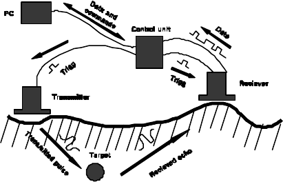
In its simplest form the RAMAC/GPR system consists of an
external PC, a Radar Control Unit, a transmitter antenna and a
receiver antenna. The Radar Control Unit is connected to the
transmitter and the receiver antenna with optical fibres and to
the computer with a parallel communication cable.
Figure 2.1 shows a schematic diagram of the system when
connected. Note that this picture refers to the case where the
transmitter and receiver are located in different modules. The
general principle is still the same also for shielded antennas.
Figure 2.1 General description of the principle
In GPR context the following terminology is often used:
Sample:
In a digital system, the incoming signal (to the receiving
antenna) is measured a certain number of times per unit of
time. The result of every such measurement is a numeral, a
sample. A defined number of samples are used to construct a
trace.
www.malags.com
7
Trace:
At each point of measurement along the profile, a specific
number of samples are collected. Together, these samples
make up a trace, an envelope of the received waveform.
Profile:
A collection of traces along a line or transect.
Direct wave:
This is the part of the energy that travels the shortest distance
between the transmitter and the receiver. When collecting a
sample, the CUII sends a timing signal (a control signal) to the
transmitter and receiver antenna respectively. After the
transmitter has received the signal, it generates and transmits
radar pulses through the antenna. The pulse then propagates
through the medium. Reflections occur from underground
objects, structures and other materials where there are
changes in subsurface electrical properties.
Once the receiver has detected the control signal, it collects a
sample and passes it to the CUII. By repeating this process at
very finely controlled intervals, the CUII can collect all the
samples in a trace. The CUII places each incoming sample in
its correct position in the current trace. When the trace is
complete, it is sent to the computer where it is saved on the
hard disk and displayed on the computer monitor.
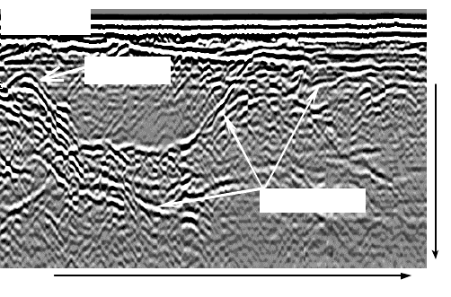
During data collection, the whole system is transported along
the line to be investigated, while collecting and recording
traces at defined distance or time intervals. The result is a
continuous profile record of subsurface conditions along that
line (see Fig 2.2), a so-called radargram.
www.malags.com
8
SOIL LAYERS
BOULDER
Distance
D
e
p
t
h
SURFACE
Figure 2.2 An example of a continuous record of radar traces.
2.2 Basic information in investigation depths and
velocities
The problem of range (depth) vs. resolution is well known for
the type of investigations that GPR represents. Sufficient
penetration depth may be achieved but it may require a low
frequency that reduces the resolution. Range is defined as the
distance at which a target can be detected. Resolution on the
other hand is defined as the smallest size an object or thinnest
layer that may be detected. There often is a compromise
regarding the choice of antenna frequency for a particular
application at a specific site.
The depth penetration with different frequency antennas varies
greatly depending on local soil conditions. Primarily the
depth/resolution requirements and the soil conditions at the
site determine the choice of antenna frequency. The table
below is hoped to be of assistance when selecting antenna
frequency based on the depth interval of interest.

www.malags.com
9
Table 2.1. Approximate depth ranges for different antenna
frequencies.
Antenna
frequency
(MHz)
Lower limit
of object
target size
(m)
Approximate
depth range *
(m)
Approximate penetration
depth (m)
100 0.1 - 1 2 - 15 15 - 25
250 0.05 - 0.5 1 - 10 5 - 15
500 0.04 1 - 5 3 - 10
800 0.02 0.4 - 2 1 - 6
* In normal geological environment absent of low resistive
layers
For the interpretation part the velocity of different geological
environment is needed for the best possible depth
interpretation. The following velocities can then be used (Table
2.2). It has to be remembered that the values given are only
approximate, and can vary greatly with the water content in the
medium. The larger value given for velocity applies to
unsaturated media.

www.malags.com
10
Table 2.2. Approximate values of ?r (relative permittivity) and
the corresponding velocity. e
r varies greatly with the water
content in the medium. The larger value given for velocity
applies to unsaturated media.
Medium
er
Velocity
[m/µs]
Air 1 300
Fresh water 81 33
Limestone 7 - 16 75 - 113
Granite 5 - 7 113 - 134
Schist 5 - 15 77 - 134
Concrete 4 - 10 95 - 150
Clay 4 - 16 74 - 150
Silt 9 - 23 63 - 100
Sand 4 - 30 55 - 150
Moraine 9 - 25 60 - 100
Ice 3 - 4 150 - 173
Permafrost 4 - 8 106 - 150
www.malags.com
11
3 Radar Control Unit CUII
_________________________________________________
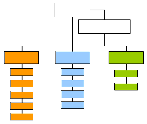
The Radar Control Unit CUII is the main part of the
RAMAC/GPR system. As seen in Fig. 3.1, the CUII is
compatible with all current RAMAC antennas, both unshielded,
shielded and borehole antennas.
Shielded
antennas Unshielded
antennas Borehole
antennas
250 MHz
500 MHz
800 MHz
1000 MHz
25 MHz
50 MHz
100 MHz
200 MHz
100 MHz
250 MHz
100 MHz
RAMAC/GPR
Control Unit II
Multi Channel
Modules MC4, MC16
Figure 3.1 An overview of all antennas that can be used
together with the CUII.
The CUII is the administrator for data collection. It consists of a
power supply, an analogue section that generates the crucial
control signals and an internal computer. A 32-bit processor
controls transmitter and receiver timing, sampling and trace
intervals, stores raw radar data in a temporary buffer and data
transfer to the PC interface.
For quick and easy operation, calibration and set up defaults
parameters are stored in the internal memory.
www.malags.com
12
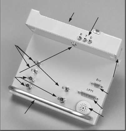
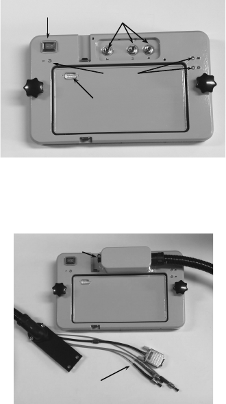
The unit has (see Fig. 3.2 below):
?? a parallel port for PC communication, see Chapter 7
?? connectors for an external trigger (distance-measuring
devices), see Chapter 9
?? input power, see Chapter 7
?? fibre optic links to the transmitter and receiver antennas
respectively, See Chapter 7.
The CUII requires no warm up time and is ready for immediate
data acquisition.
Multi -
channel
connections
Fiber optic
connections
Parallel port
Function
LED
On-Off
switch
Battery
position
Carrying handle with
fastening device for
the cables
Beeper
Encoder
Connection
Figure 3.2 The Radar Control Unit CUII
During operation the CUII is mounted on a specially designed
back-pack holder or put in to the CUII back-pack:
www.malags.com
13
?? Mounting the CUII to the back-pack holder: The CUII is
attached to the backpack with the 4 screws that have black
plastic grips. Once the battery is mounted on the control
unit there is a strap on the soft backpack that should be
attached below the battery and firmly tightened. The
shoulder straps can be adjusted for maximum comfort for
the operator. This holder is easily combined with a PC
holder to give you a convenient working surrounding.
?? CUII in the RAMAC back-pack:
For assembling the CUII to the rest of the RAMAC/GPR
system, see Chapter 4, 5, 6 and 11.
www.malags.com
14
4 Unshielded antennas
_________________________________________________
The unshielded antennas consist of separate transmitter and
receiver electronics to which the antenna elements are
attached. The antennas can then be used with antenna
handles, a skid box or an antenna sledge (see Chapter 10).
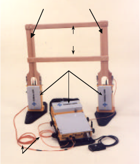
The complete RAMAC/GPR system is shown in Fig. 4.1,
where the antenna electronics are mounted to the antenna
elements together with wooden handles.
Radar
Control
Unit
Batteries
Trigger Status Box
Tx
Rx
Fiber Optic Cables
Spacers
Antenna Handles
Figure 4.1 Unshielded system connected with the 200 MHz
antennas and handles with 0.6 separators.
4.1 Antenna electronics
The unshielded antenna electronic unit for the transmitter
generates electromagnetic energy and transmits it to the
attached antenna elements every time a trigger signal is
received from the CUII through the optical fibre (labelled T).
These high amplitude pulses (typically 370V) are fed to the
antenna elements at a repetition rate of 100 kHz. The antenna
element transforms these pulses into radar impulses at a
www.malags.com
15
centre frequency, which is dependent on the antenna
dimensions. The unit has one optical connector for the
transmitter trigger, a connector for a battery pack, a power
switch and a LED.
See Figure 4.2.
When flashing, the LED on the transmitter electronic indicates
trigger pulses are being received from the Radar Control Unit.
No light indicates no power is being received by the
electronics. A steady light indicates that no Trigger pulses are
received from the Radar Control Unit.
NOTE: As soon as the power switch is turned on with a battery
connected the transmitter starts firing pulses. There is a short
"warm-up" sequence of the antenna whereby it is
recommended to turn the electronics on a few minutes before
data collection starts. A good rule of thumb is to turn on the
transmitter first when preparing for a survey.
Rubber O -ring
Antenna
hooks
Battery
hooks
Power switch
Input power
Tx Fiber optic
Antenna handle hooks
Optical connectors Rx trigger and data
Figure 4.2 Unshielded Transmitter Figure 4.3 Unshielded
Receiver
www.malags.com
16
The receiver electronic (Fig. 4.3) digitises the received signals
from the antenna to a 16-bit numerical integer value (0-32768
and +32767). These numerical values represent the
amplitudes of the received radar signals. This digital collected
data is transmitted to the CUII via the fibre optic cable labeled
D). A second fibre optic cable labeled R is used to receive the
trigger signals from the Radar Control Unit. There are also a
connector for a battery pack, a power switch and two LEDs.
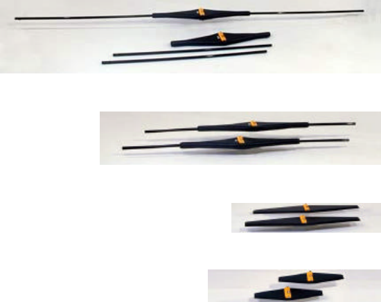
4.2 Antenna elements
Each unshielded antenna frequency consists of a pair of
transmitter and receiver antenna elements. These elements
are connected to their respective unshielded electronic units
via a D-sub connector. The connectors are different genders
for the transmitter and receiver antenna elements to eliminate
the possibility of incorrect connections.
A rubber O-ring is fitted to the connecting metal plate for water
resistance and should be inspected periodically. The antenna
elements must be fitted to the electronics by properly locking
the metal clips.
www.malags.com
17
The antenna elements are also sealed to be water-resistant,
however, they are not guaranteed to be water-proof and
should never be submerged in water.
25 MHz
50 MHz
100 MHz
200 MHz
Figure 4.4 Unshielded antennas
The 25 and 50 MHz antenna elements consist of a central
element with detachable end pieces. When mounting these
pieces it is important that they are properly fitted so that the
double O-rings at their ends seal properly against moisture
and that the electrical connection is proper. The 100 and 200
MHz antenna elements are in one piece. See Figure 4.4
above.
www.malags.com
18
Antenna Handles are used when profiling without the use of
Skid Box or Antenna Sledge. Use of the handles is
recommended mainly for the low frequency antennas where
the station separation is comparably great. For more
information see Chapter 10.
4.3 Operation modes
The unshielded antennas can be operated in a variety of
modes for different survey techniques. They are:
?? Reflection profiling: This is the most common type
of operation. The antennas are mounted at a fixed
separation and moved along a line. Measurements
are taken at even distance or time intervals.
?? Velocity profiling (common midpoint (CMP) or wide
angle reflection and refraction (WARR) type of
profiling): In order to calculate an accurate depth
scale the measured reflection times must be
converted to velocities of the radar signals. This
conversion can be made empirically by assuming a
velocity based on experience or existing data such as
the relative dielectric permittivity of the medium being
surveyed. Otherwise, the radar velocity can be
calculated by measuring time delays of the reflected
signals as various transmitting and receiving antenna
offsets.
?? Cross-scanning (tomographic type of profiling):
Cross-scanning is a technique used to investigate
e.g. the integrity of an area located scanning
between the antennas. This can be e.g. concrete
constructions or a rock mass between two tunnels.
RAMAC/GPR allows you to collect cross-scanning
data that needs to be processed in external software
www.malags.com
19
in order to produce images of the area between the
antennas. For further information about such
software the user is recommended to contact MALÅ
GeoScience directly.
www.malags.com
20
5 Shielded antennas
_________________________________________________
Presently, Malå GeoScience manufactures 100, 250, 500, 800
MHz and 1 GHz shielded antennas. The 100, 250, 500 and
800 MHz antenna’s interface with the Shielded Electronics Unit
is described below (see also Fig. 5.1 to 5.4). The 1 GHz
antenna contains its own built-in transmitter and receiver
electronics and is described in Chapter 6.
A shielded type of antenna means that the energy is only
transmitted in one direction. It is also insensitive to radiation
from all directions except from the bottom part of the antenna
where the receiving antenna element is located. The shielded
antenna element comprise both transmitter and receiver
antenna elements in a single housing. These consist of a
modified bow-tie antenna construction with the receiver
element at the front end and the transmitter element at the
back of the housing.
The front of the antenna is equipped with a hook for attaching
a tow handle or strap. A fastening device at the back of the
housing accommodates the distance-measuring wheel This
wheel operates as a triggering device instructing the
RAMAC/GPR system to collect traces at operator pre-set
distant intervals (see Chapter 9). Detachable wear plates to
help insure long antenna life are also provided. See Figures
5.1 and 5.2.
www.malags.com
21
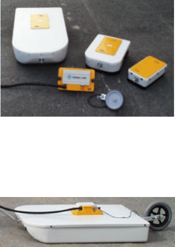
Figure 5.1 From left to right: Shielded 250, 500 and 800 MHz
antennas. In front: electronics unit and survey wheel.
Figure 5.2 Shielded 100 MHz antennas, electronics unit and
survey wheel
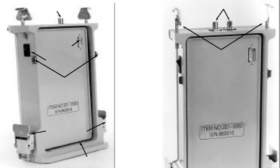
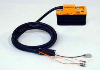
The Shielded Electronics Unit is used to operate the
RAMAC/GPR shielded antennas (see Fig. 5.3 and 5.4). The
Shielded Electronics Unit contains both the transmitter and the
receiver electronics. Power to the electronics is provided by a
standard RAMAC/GPR battery pack. Communication with the
CUII is managed via three optical fibres and a cable for a
distance-measuring wheel. These cables provided are in a
protective housing.
www.malags.com
22
Power Switch
Fiber optic connectors
LED’s
Battery connector
Figure 5.3 Shielded electronic unit without the optical fibre
cable.
Fiber optic and enocer connectors
to Radar Control Unit
Encoder connection
Figure 5.4 Shielded electronic unit with connected cable hose.
As in the unshielded electronics LED-indicators show the
status of communications between the Shielded Electronics
Unit and the Radar Control Unit.
When flashing, the T and R trigger pulses are being received
from the CUII. No light indicates no power is being received by
the electronics. A steady light indicates that no trigger pulses
are received from the CUII.
When flashing, the LED labeled D indicates that data are sent
to the CUII. No light indicates no power is being received by
the electronics. A steady light indicates that no data are being
transmitted to the CUII.
www.malags.com
23
As seen a steady light on a LED indicates an interruption in the
optical communication. This means either a fibre optic cable
has failed or, the fibre optic connectors need to be cleaned
with the compressed air can provided with the system. When
none of the LED’s is blinking a power failure to the electronics
unit has occurred. Replace or recharge the battery. If the
electronics still do not function with a fresh battery then there is
an internal failure in the Shielded Electronics Unit.
To mount the shielded electronic on a shielded antenna,
perform as follows;
?? Place the Shielded Electronics Unit on the antenna with
facing the cable hose towards the antenna front.
NOTE: DO NOT TRY TO MOUNT THE ELECTRONICS IN
THE REVERSE DIRECTION. THIS WILL DAMAGE THE
ELECTRONIC UNIT.
?? See to that the unit is firmly attached to the antenna
before you fasten the two black mounting screws.
?? Mount a battery pack to the electronic unit.
?? When appropriate mount the survey wheel at the
antenna rear and connect the signal cable to the
electronics unit.
?? Attach the cable hose to the backpack as a strain relief.
?? Connect the optical fibers labeled T, D and R to the
CUII.
?? Connect the signal cable from the survey wheel to the
CUII.
www.malags.com
24
6 1 GHz shielded antenna
_________________________________________________
The 1 GHz shielded antenna (Fig. 6.1) for RAMAC/GPR has
been designed for surveys on shallow environments such as
roadbeds, concrete constructions, archaeological sites etc.
With the antenna a survey depth in these materials of roughly
1 m (two way travel time of 15-25 ns) can be expected. Local
conditions may however affect this value in both directions.
Figure 6.1 Shielded 1 GHz antenna together with cable hose.
Power is fed through the standard RAMAC/GPR battery pack
that attaches to the top of the antenna. Alternative power
supplies are either to use of the alkaline power pack available
as an extra item or to feed the required power through an
external power cable to the 9-pin connector on the top of the
antenna. The power requirement for the 1 GHz shielded
antenna is 6-14 V DC and a minimum of 1.5 Ah.
Preparing the antenna for survey includes:
?? Connecting the optical fibres to the three connectors. It
is important to connect the fibres as they are marked or
to connect the corresponding colours to the right
connector at the control unit.
www.malags.com
25
NOTE: Take care when bending the fibres under the metal
cover that attaches to the connectors with the two screws. The
fibres should form a soft bend in order to obtain good light
conditions. A too hard bend may result in loss of trig pulses to
either Tx or Rx or the loss of data from the Rx to the control
unit.
?? If the measuring wheel is used then the connecting
cable should be connected to the cable from the plastic
hose.
?? At the control unit the optical fibres should be attached
firmly as well as the electric cable for the measuring
wheel. The latter attaches to the 9-pin connector
marked ENC.
?? The metal plate at the end of the plastic hose may be
attached to the control unit using one of the screws for
the backpack. This gives a firm attachment and avoids
fibre problems.
When the antenna is connected properly and the charged
battery pack is connected properly we recommend you turn on
the antenna and let it ”warm up” for about 3-5 minutes before
performing any measurements. The ”warm up” period reduces
the vertical signal deflection of data.
A red LED light on the antenna indicates that the power is
switched on. At this stage the transmitting element starts
transmitting pulses at the normal rate of 100 kHz. Now the
control unit and external PC can be connected and turned on.
www.malags.com
26
7 Power supply, Optical fibres and
Communication cables
_________________________________________________
7.1 Power supply
Each electronic component in the RAMAC/GPR system is
powered by specially designed battery packs. These packs are
interchangeable between system components.
Rechargeable Ni-Cd or Pb-acid battery packs are available.
The capacity of the Ni-Cd packs is approximately 5.7 Ah. The
Pb-acid battery packs have an approximate 8 Ah capacity.
The operating time of the system is dependent on the charge
cycle history of the batteries. Normally, maximum operating
time is not reached until the batteries have been fully charged
and discharged 3-5 times. Optimum performance is achieved
through fully discharging and recharging the battery packs.
Note that batteries lose efficiency in cold temperatures. So
insulating the electronics and battery packs in cold climates
will prolong the battery life as the electronic units generate
internal heat during operation.
The batteries are mounted by simply placing the battery
compartment with the lid on the rear short side under the
corresponding groove in the electronic units. The front end or
the battery pack has a locking tab on the plastic housing.
Gently press on the front end of the battery until the lid is
released from the groove before removal.
A special empty battery pack for the CUII and unshielded
antennas is also available. It can hold six standard D-size-
cells. These can easily be replaced and are suitable when
www.malags.com
27
operating in areas where recharging of the batteries is not
possible.
NOTE: Alkaline batteries will NOT operate the Shielded
Electronics Unit.
7.2 Optical fibres
The RAMAC/GPR Radar Control Unit communicates with the
transmitter and receiver electronics through fibre optic cables.
The data transfer rate through the fibres is up to 4 Mbytes/sec
and they operate:
?? Trig signals to the transmitter element from the CUII
?? Trig signals to the receiver element from the CUII
?? Data from the receiver element to the CUII.
The antennas can be operated through the standard set of
optical fibres for RAMAC/GPR. These optical fibres come in a
standard length of 4 m. They are also available in lengths up to
100 meters or more for applications such as CMP
measurements or cross scanning where the two antennas
have to be separated from each other.
For the shielded antennas Malå GeoScience have designed a
special set of fibres housed in a plastic hose for convenience
(Fig. 5.4 and 6.1). This is to protect the fibres from damage
when operating the antenna in e.g. rough environments. The
attachment of the optical fibres to the antenna includes a metal
cover over the optical connectors. This is in order to protect
the connectors and the fibres at their attachment on the
antenna. When sampling at high sampling frequencies as e.g.
100 000 MHz the bending of a trig fibre can play an important
role for the time displacement of the pulse in the time window.
This is due to the short time interval that each sample
represents at these frequencies.
www.malags.com
28
For using the shielded antennas at longer distances from the
CUII than 4 m there is also a plastic hose of 20 m length
available. Alternatively the standard optical fibres with lengths
up to 100 m can be used.
All the fiber optic cables provided with the RAMAC/GPR are
reinforced with Kevlar? and feature stainless steel and
ceramic tip connectors. However, care should always be
exercised when handling this type of cable. The light carrying
fibre core is only 50 micrometer in diameter, which is less than
the thickness of hair.
?? Avoid excessive bending
?? Keep cables protected against physical damage
?? Keep connectors clean
7.3 Communication cable
Parallel data transfer between the RAMAC/GPR CUII and the
external PC is used as a standard.
It should be noted that data transfer is more secure with
shorter cables. For best performance use an IEEE 1284 (ECP)
compatible parallel cable that is less than or equal to three
meters long.
For configuration of external PC communication ports, see the
RAMAC GroundVision Software manual.
www.malags.com
29
www.malags.com
30
8 Multi-channel modules
_________________________________________________
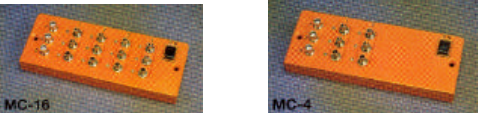
The RAMAC/GPR Multi-channel unit (MC-4 and MC-16) is an
optional add-on module to the CUII (See Fig. 8.1 and 8.2). The
Multi-channel comes in two versions, MC-4 with up to 4
recording channels or the MC-16 with up to 16 recording
channels. The MC-16 connects 4 transmitter and 4 receiver
antennas.
The Multi-Channel unit has the capability to operate any of the
optional receiver inputs to any transmitter (controlled through
software). The repetition rate of the CUII is shared among the
defined channels, i.e. the effective repetition rate equals 100
kHz (standard) over the number o f channels defined. For
more information see RAMAC GroundVsion Software manual,
version 1.3.
Figure 8.1 Multi-channel units, MC-16 and MC-4.
www.malags.com
31
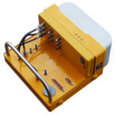
The multi-channel unit is connected to the D-sub connector on
the CUII (see Fig 3.2) and the fixed firmly with two skrews. The
multi-channel unit is provided with three short fibre optical
cables for connection between the add-on unit and the CUII.
The lower T, D and R connectors on the CUII are used to
connect the multi-channel unit (see Figure 8.2 and 3.2).
Figure 8.2 The Multichannel MC-4 add-on mounted on the
CUII.
www.malags.com
32
9 Trigger devices
_________________________________________________
The most efficient method of data acquisition is to use a
distance-measuring wheel or profile encoder (hip chain) to
control the collection of radar data. Data is acquired at user
defined distance intervals so that the position of each trace
along a survey line is given by the position of a radar trace in
the data file. This simplifies data acquisition procedures and
locating the position of reflections.
The hip chain can be used when scanning from a sled or
when the transmitter and receiver are mounted on the carrying
handles. The hip chain comes with cotton string of a length of
2800 meters in a roll. The string is made of pure cotton that
decomposes in nature. Its greatest advantage is in trackless
and undulating terrain where it would be impractical to use a
measuring wheel.
The measuring wheel may be more appropriate to use for
distance control for surveys on flat terrain or in urban areas (on
Skid Box or shielded antennas). The measuring wheel is
attached to the tow handle of the skid box or directly on the
shielded antennas. The measuring wheel for Skid boxes
operates through a rubber band (models 9610-) that circles the
pulse encoder. In wet or snowy terrain it is important that the
rubber band and the wheels are kept clean in order to let the
band run free.
All distance-measuring devices for the RAMAC/GPR use an
optical encoder that transmits electrical pulses to the CUII. A
distance calibration file is used to convert the number of pulses
to the correct distances. The operator can create calibration
files or use those supplied with the installation diskette.
These calibration files for different length encoders contain
www.malags.com
33
information about both the numbers of pulses that are counted
per meter and the rotation direction in which it will calculate the
optical pulses correctly. The triggering of readings from the
GPR will ONLY be done in the positive direction of rotation.
This, so you should be able to move the wheel back-wards
without any readings made. However, if the wheel needs to be
rotated constantly in the opposite direction this can be
accomplished by changing acquisition direction in the GPR
software.
NOTE: When using both devices you should keep accurate
record of your calibration files for the devices so the right one
is selected for the device used at each measurement
occasion.
NOTE: The distance interval when using a measuring wheel
should be set to a greater value than 0.003 m. The measuring
wheel counts about 427 pulses/m, which is less than one
pulse/ 2mm. A distance < 0.003 m will correspond to zero
pulses and cause the antenna to start collecting data
immediately at full speed.
www.malags.com
34
10 Other accessories
_________________________________________________
10.1 Antenna handles
The wooden antenna handles (see Fig. 4.1) are used for
carrying the unshielded antennas and stabilizing the antennas
during measurements (when not using a skid box).
The handles are mounted together using the set of 8 screws
and nuts. Mounting both horizontal bars for maximum stability
is strongly recommended. The bars come in 0.6, 1.0 and 2.0
meters lengths for use with the 200, 100, 50 MHz antennas
respectively. These are only recommended antenna
separations. The operator is however free to select other
transmitter/receiver offsets as desired.
The handles attach to the antenna electronics using the metal
locks on each side. It may be necessary to adjust the metal
hooks on the electronics for firm attachment. The handle tops
are intended for use when the antennas are moved individually
without the horizontal bars. This is the case when performing
e.g. CMP or WARR type of surveys.
NOTE: If antenna separations other than the standard ones
mentioned are used it will be necessary to edit the header file
for correct depth scales to be displayed by the software.
Wooden separators or the 25 MHz antennas are not practical
because the recommended antenna separation for this
frequency is 4 meters. MALÅ GeoScience provides 4 m long
strapping for this purpose.
www.malags.com
35
10.2 Skid box
The glass fibre skid boxes come in two sizes, one for the 100
MHz and one for 200 MHz antennas. The robust design of the
skid boxes make them well suited for operations in rugged
terrain as well as on flat terrain where smooth operation and
movement at constant speed are required.
The mounting of the antennas in the Skid Box is seen in Figure
10.1.
It is important that the antenna elements are firmly attached to
the bottom using the rubber ties. The optical fibres pass
through the pulling handle. A stress relief arrangement inside
the handle prevents the optical fibres from being pulled out of
the handle. The following procedures should be followed:
?? Connect the short plastic tube to the handle firmly with
a screwdriver fastening the 10-cm black rubber tube
?? Thread the bottom ends of the optical fibres through
the front hole in the Skid Box into it.
?? Mount the short plastic tube through the same hole
making sure that the optical fibres are not damaged.
?? Fasten the plastic tube in the Skid Box using the metal
clamp.
?? Place the Antenna electronics with its antenna element
inside the Skid Box.
?? Fasten the antenna elements using the rubber ties.
?? Attach the optical fibres to respectively antenna.
?? Attach the corresponding ends of the fibres to the
CUII.
?? Attach the stress relief to the backpack.
?? If necessary mount the Skid Box cover using the
rubber ties.
www.malags.com
36
NOTE: If this is done, remember to turn on the Power switches
on the antennas before survey start.
?? If the Hip Chain is used it can be mounted on the
pulling handle.
?? If the Measuring Wheel is used it is mounted on the
metal clamp on the pulling handle.
?? If the Wheel set is used it should be attached using the
rubber ties fastened to the plastic clamps on each side
of the Skid Box.
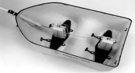
Figure 10.1 Skid Box with unshielded 200 MHz antennas
mounted
10.3 Antenna Sled
An alternative to a skid box is the Antenna Sled. It consists of
a tough plastic mat with fastening devices for 100 and 200
MHz antenna elements and stabilising tubes for the edges.
This sled can be towed by hand on flat surfaces. The Hip
Chain can be used as measuring device when attached to the
operator’s belt.
www.malags.com
37
www.malags.com
38
11 Start up of your RAMAC/GPR CUII
_________________________________________________
In order to operate the system, the following items are
required:
?? RAMAC/GPR CUII
?? Transmitter and Receiver antenna electronics, if
unshielded antennas are used
?? Transmitter and Receiver antenna elements,
unshielded or shielded
?? Optical fibers:
One transmit (single) and one receiver (dual)
fiber optic cable for unshielded configuration or
Cable-hose assembly for shielded configurations
?? A rechargeable power supply for each electronics unit
?? Parallel data cable for ECP communication
?? External PC. Minimum requirements:
Windows 95, 98, ME, 2000, NT or XP
Processor: 100 MHz Pentium
RAM Memory: 32 MB
Disk capacity: Minimum 100 MB recommended
Graphics: 800x600
Communication: ECP Parallel port (IEEE 1284)
?? Data collection software installed (GroundVision)
In addition the above mentioned there exists different length
measuring devices, pulling and carrying handles as well as
skid boxes which are regarded as accessories, as seen in
Chapter 7.
www.malags.com
39
11.1 Connecting the system components
?? Mount the antenna electronics to the antenna element
according to Chapter 4 - 6.
?? Connect the CUII (labeled LPT 1) to the external PC
parallel port with the parallel data cable provided with
the system.
?? Connect appropriate fibre optic cables between the CUII
and the antenna electronics as follows:
?? For unshielded systems: Single fibre optic cable
from the fibre optic connector labeled T on the
CUII to the Transmitter Electronics. Dual fibre
optic cable from the fibre optic connectors
labeled D and R to their respective connectors on
the Receiver Electronics
?? For shielded systems: Fibres labeled T, D and R
should be attached to their respective fiber optic
connectors on the CUII.
NOTE: It is essential to attach the strain relief to the CUII in
order to protect the optical fibers and connectors. Failure to do
so will likely result in damaged cables.
?? Attach the appropriate Measuring Device (if any
purchased) and connect to the port labeled ENC.
?? Turn on the power on the antenna electronics and the
CUII. Turn on the PC and start the data acquisition
program GroundVision. Your RAMAC/GPR system is
now ready for operation.
www.malags.com
40
11.2 Running a survey
When starting out for a survey you should always have an idea
about the depth/time section you are about to survey. This not
only determines your depth/time section to be recorded but
also your choice of antenna frequency for the survey. One
antenna can be used for a wide range of depth surveys but it
might not possess the maximum depth resolution required for
your survey.
Starting a survey routine is a simple task with RAMAC/GPR
CUII. CUII offers you a fast way of parameter choice through
the "Pre-set" parameter settings. Factory default and user
selected parameters can be saved for later use. First-time
GPR users will find the default settings to be helpful in setting
up their system parameters.
During data collection the radar data and other information are
displayed on the computer screen. Once data collection is in
progress modifications to display functions, screen colors, gain
settings can be performed without affecting the start
parameters or the recorded data. The data collection can be
interrupted and resumed at any time. This feature facilitates
the entry of field notes and comments. For more information
see RAMAC GroundVision software manual, version 1.3.
RAMAC/GPR CUII offers you four different ways of acquiring
data. They are:
?? By the use of a distance measuring device (distance
triggered)
?? Through the external PC keyboard (by pressing the
SPACE button)
?? By taking readings at fixed time intervals
We recommend measurements be performed using some kind
of distance measuring control. This way you can relate the
www.malags.com
41
results to a fixed geographic location. Using time triggering is
as an alternative for lake, river and wetlands surveys where
the equipment may be setup in a boat or raft or, for studies
where a Global Positioning System may be deployed for
positioning control.
?? The selection of triggering method depends on a
number of factors such as:
?? The purpose of the survey
?? The type of antenna
?? The need for post-processing of data
?? Positioning control
?? Type of terrain
?? The accessories for your equipment
www.malags.com
42
Trouble shooting
_________________________________________________
As with all electronic equipment it is important to handle the
CUII and the antennas with great care and to avoid harsh
handling and bumps against the electronics. During transport
of the equipment the CUII and antennas should be packed
properly and firmly in a transport box.
Care should also be taken for the optical fibres so they are
protected against dust and dirt. When finishing a survey the
equipment should be checked and packed properly in the
transport case. Batteries should be kept charged if possible
and if stored away for longer time they should be charged now
and then.
The most common types of problems you will find listed below
together with our recommended actions. If you do not succeed
following these actions we recommend you please contact
your closest MALÅ GeoScience sales representative.
An error messages appear on the computer screen
when taking a reading, Communication problem:
Cause Action
Communication
problem between the
PC and the CUII Check the data cable
Check that control unit is
on
Check battery for control
unit
Check communication set
up in the data acquisition
programme
www.malags.com
43
Only a straight line appears on screen when taking a
reading:
Cause Action
The transmitter is not
turned on Turn the transmitter on
Signal search has not
not been performed Perform signal search
The transmitter is not
triggered by the CUII
Check the LED located on
the transmitter unit. If it
blinks the electronics
receives a correct trig
signal from the CUII
If the LED does not blink:
Check for dirt in the optical
connector in the
Transmitter
The ground is too
conductive for a GPR
survey
Check the system by
collecting a trace with the
antenna above the ground.
No traces are collected when survey starts:
Action
Check Trig setup and calibration with measuring wheel file.
Move the antenna in the correct direction.
Traces disappear during survey and only a straight line
appears intermittently:
Action
Check Tx fibre connection at the antenna.
www.malags.com
44
12 How to assemble the RAMAC/GPR
Cart
__________________________________________________
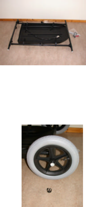
1.
When receiving the CART you
will have to mount it before use.
You’ll find four pieces in the case,
one handle, one frame with the
skid plate attached, 4 wheels and
a plastic bag with smaller
accessories inside. The first
piece that you must start the
assemble with is the frame with
the attached skid plate.
2.
The first step in the mounting process is
to attach the wheels. To be able to
fasten the wheel on the frame you will
first have to loosen the small plastic
clips. By doing that the wheel will fit
properly and to fix it, just replace the
plastic clip.
www.malags.com
45
The left back wheel is equipped
with an encoder. One of the
wheels are different from the
others and will only have the
possibility to mount the needed
o-ring. The o-ring can be found
in the small plastic bag with the
other accessories. This o-ring
attached on the wheel must
then be mounted on the frame of the cart as well.
The picture will show how it will look like.
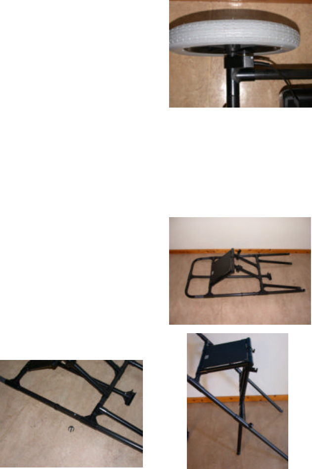
3.
After the wheel has been
mounted it’s time to prepare the
handle piece. First you have to
unfold it and put the tray in its
right position. This is done by
removing the lower plastic clips
on the legs. Press the fortress
for the tray upwards and then
restore the plastic clips.
www.malags.com
46
4.
Now it’s time to mount all
the pieces together into one
RAMAC/GPR Cart. Start by
assembling the inner legs of
the handle piece to the
frame. Secure the mounting
with the locks. When the
inner legs are fasten, mount
the outer legs at the front of
the frame.
Now we have a mounted
cart in front of us and the
only thing left to do is to
fasten the safety leg, if you
have a 250MHz Cart. This
leg does not exist for the
500MHz cart.
www.malags.com
47
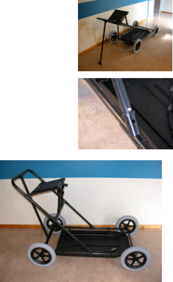
5.
The final part is to mount the equipment onto the CART.
Attach the antenna into the skid plate and adjust the straps
accordingly, the skid plate should drag lightly on the ground.
Use the velcro to attach the PC or RAMAC Monitor onto the
upper plate of the CART. Place the PC or the RAMAC Monitor
on the upper plate and place the X3M Unit or X3M Corder unit
directly on the antenna. (See RAMAC X3M Hardware Manual
for additional assembly). If you are using the Control Unit II,
mount the unit on the two hooks placed under the tray.
Have a nice survey!