How To Incorporate Dimensions Between S Add Additional Design Intent 031909
2016-06-08
: Guides 031909 Incorporatedimensionsbetweens 031909_IncorporateDimensionsBetweens tips pdf asi
Open the PDF directly: View PDF ![]() .
.
Page Count: 5
www.advsolinc.com
ASI Client Center
1-877-438-2741
Autodesk Products Tip & Tricks
Copyright 2008 – Advanced Solutions, Inc.
Product: Autodesk Inventor 2009
Topic: How to incorporate dimensions between models to add additional design intent
Written by: Paul Cetnar, Application Engineer, Manufacturing Solutions Division
Date: March 19, 2009
Hello, and welcome to another edition of our Tips & Tricks.
During my experience working with clients, they often inquire on the different methods that are available to
link dimensions from one model to another. In this edition, we’ll take a closer look at exactly how to pass
along important dimensions that we’ve captured inside one model, and easily transmit those to related
components to take design intent to the next level.
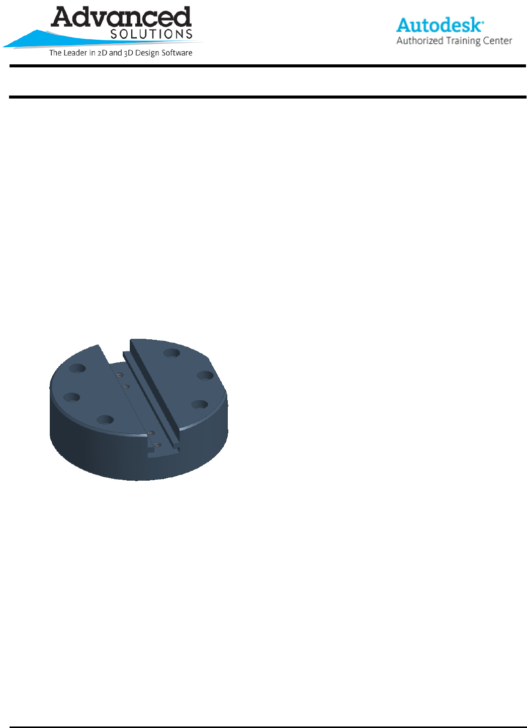
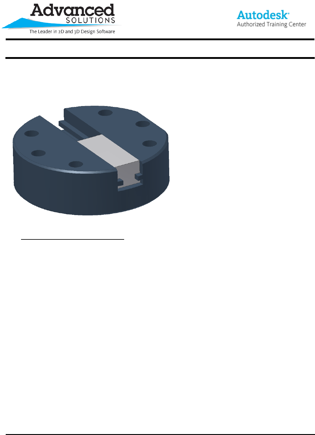
First and foremost, you’ll need to open up one of your part files in Inventor 2009. See Figure 1 for the
example I’ll be using.
Figure 1
In this example, the design intent we’ve realized is that a corresponding part will be nested inside the slot.
What this tip will show you is how we can relay the dimensions we’ve used in our current part and make
those available in the new part to not only speed up our design, but make it foolproof by using the exact dims
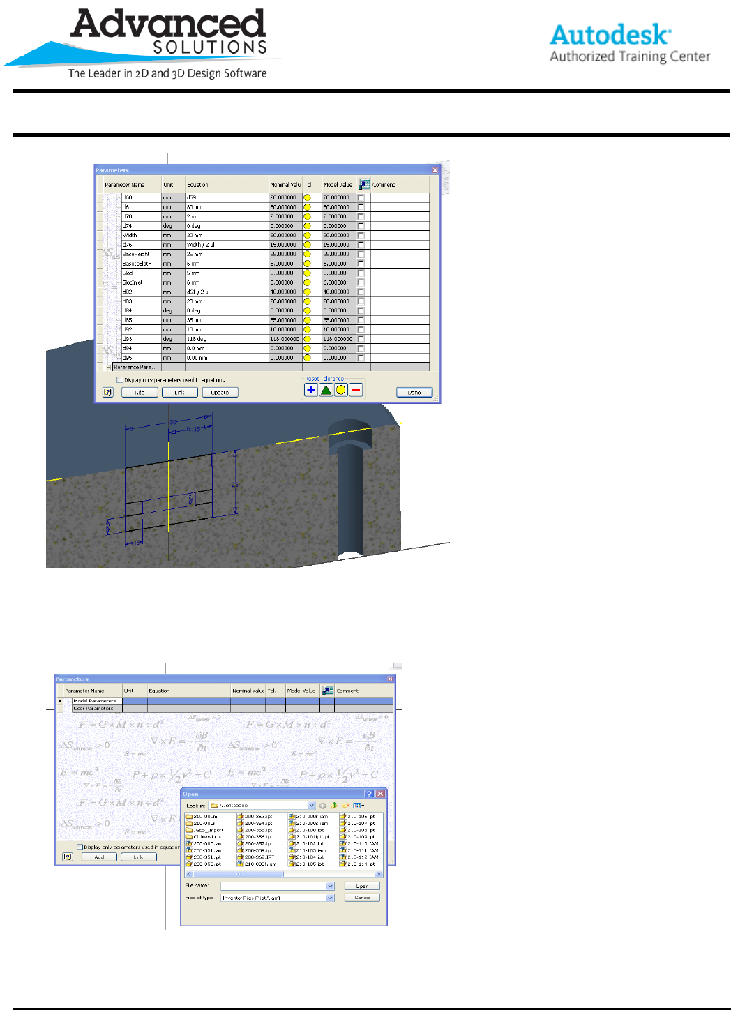
we need to incorporate. To start this process, we’re going to dig into the parameters dialogue box within our
part file (accessible from the part features tool panel or the ‘Tools’ dropdown menu). In here, I’ve renamed
some of the parameters (such as Width and BaseHeight) to make them easier to understand when sharing
with the new part. See Figure 2.
www.advsolinc.com
ASI Client Center
1-877-438-2741
Autodesk Products Tip & Tricks
Copyright 2008 – Advanced Solutions, Inc.
Figure 2
From here, we have a nice setup to transmit these dimensions to our new part. To begin the link, let’s first
start a new part file and again, enter into the parameters dialogue box. At the bottom, you’ll see an option to
‘Link’. Select the link option and in this case, we want to utilize another existing Inventor file, so change the
files of type to the appropriate selection. See Figure 3.
Figure 3
At this point, we want to select the file we are looking to import dimensions from. Simply select the
appropriate file and hit open. Once at this stage, you’ll be presented with a dialogue box similar to the
www.advsolinc.com
ASI Client Center
1-877-438-2741
Autodesk Products Tip & Tricks
Copyright 2008 – Advanced Solutions, Inc.
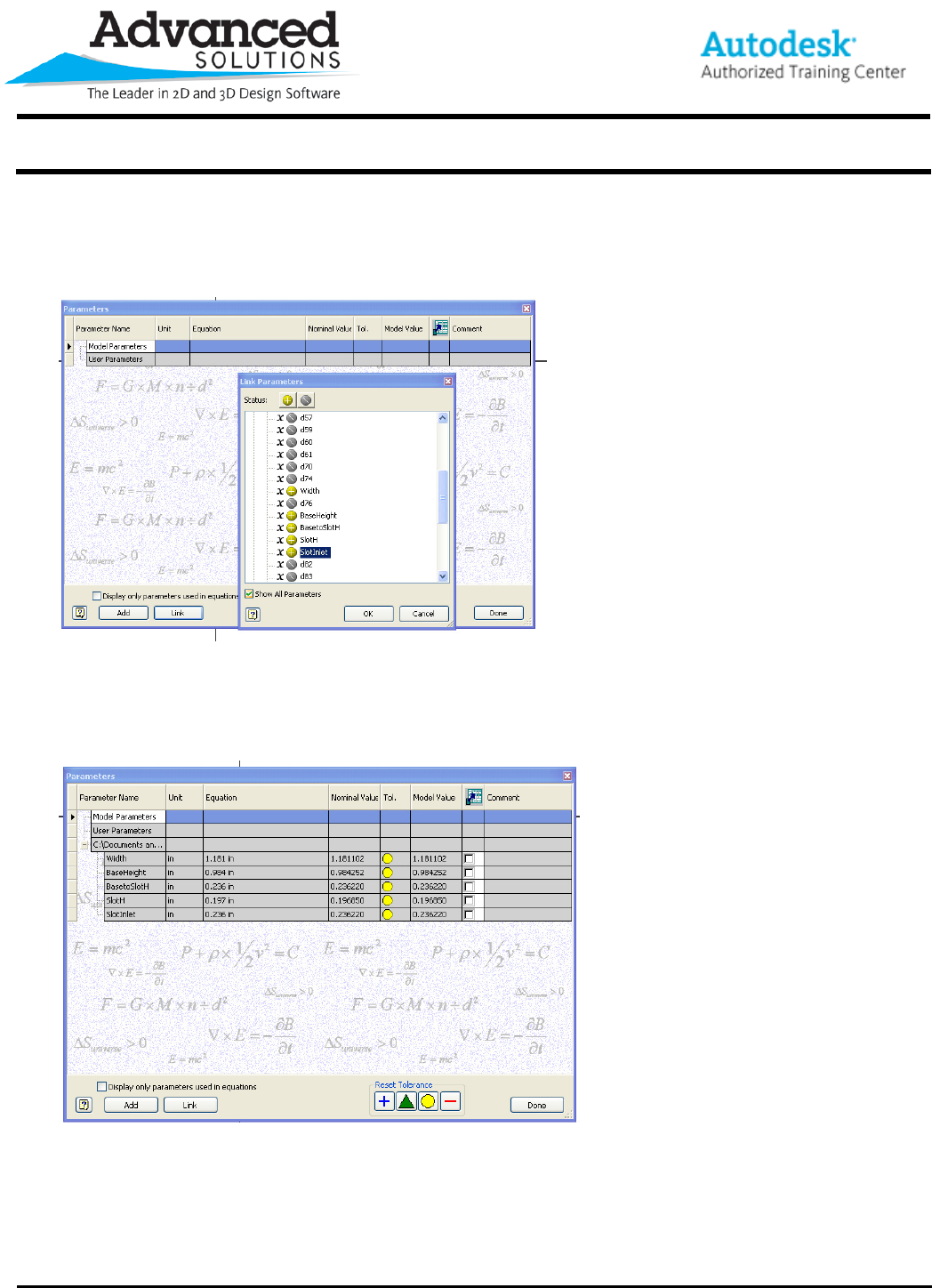
derived component where we are basically looking to access and import the dimensions we need. I’m going
to simply find the dimensions I renamed (this is where the suggestion to rename your parameters really
comes into play as we will see in this illustration) and change the symbol next to the dimensions I need so
they are included in my new part. See Figure 4.
Figure 4
Once we are complete with the import, the parameters in your dialogue box should look similar to the image
below. These linked values are now available for use within our new part to make sure our components are
matching specification. See Figure 5.
Figure 5
www.advsolinc.com
ASI Client Center
1-877-438-2741
Autodesk Products Tip & Tricks
Copyright 2008 – Advanced Solutions, Inc.
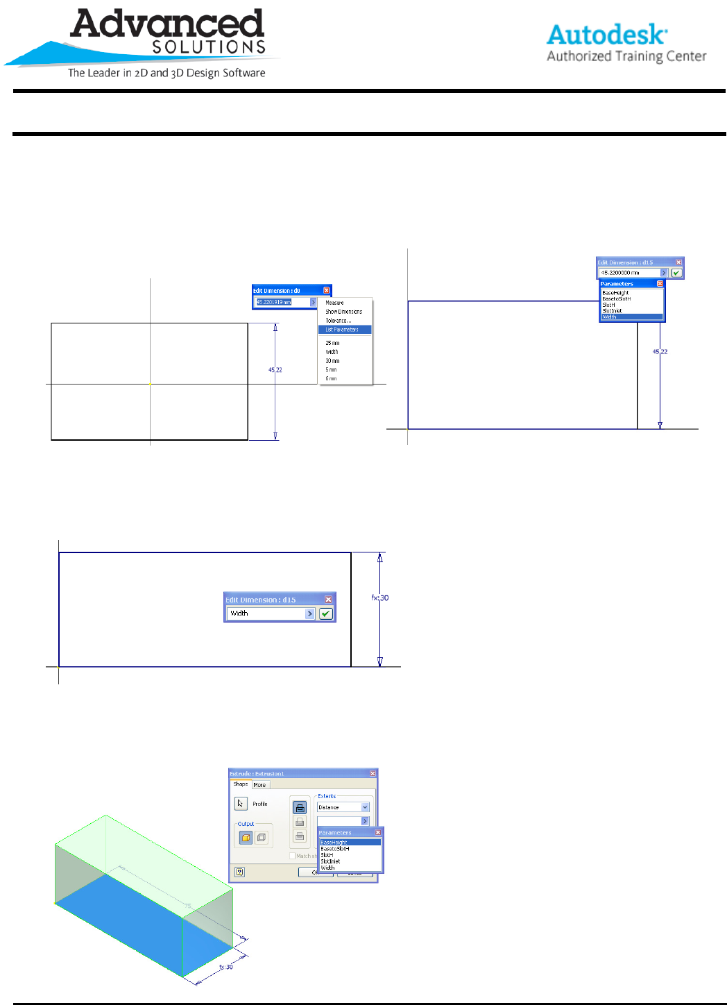
At this point, I can begin the design of my new part that will be placed into the slot of my partner component.
When I’m building my sketch I can simply reference the parameter name in my edit dimension dialogue box
(make sure your spelling is exact) or an easier route is to use the ‘List Parameters’ function (Figure 6) from
the flyout of your ‘edit dimension’ dialogue box. Once accessed, you’ll see a list of our imported parameters
(Figure7).
Figure 6 Figure 7.
By applying the height utilizing the ‘Width’ dimension from my other part, I’m instantly adding intelligence and
design intent into my new part. Once applied, your new dimension should look similar to the below image.
See Figure 8.
Figure 8
The same idea is applicable inside our Extrude dialogue box. Again, having the ‘width’ parameter, I’m able to
quickly match up the corresponding value for my new part. See Figure 9.
Figure 9
www.advsolinc.com
ASI Client Center
1-877-438-2741
Autodesk Products Tip & Tricks
Copyright 2008 – Advanced Solutions, Inc.
After applying the other dimensions for the slot, I placed the two components into an assembly file, added a few
assembly constraints and just like that, we can see how the parts come together perfectly. See Figure 10.
Figure 10
The most important thing to remember now is that since the dimensions are linked inside both files, when you
make a change to the parent dimensions in our initial component, the size of our slot is going to automatically
change, making time consuming changes a thing of the past!
Thank you again for reading this edition of the Tips & Tricks. I hope this process will assist your change order
process and ultimately decrease your time to market!
