Creating A Centerline Dimension Style 032709
2016-06-08
: Guides 032709 Creatingcenterlinedimensionstyle 032709_CreatingCenterlineDimensionStyle tips pdf asi
Open the PDF directly: View PDF ![]() .
.
Page Count: 2
www.advsolinc.com
ASI Client Center
1-877-438-2741
Autodesk Products Tip & Tricks
Copyright 2008 – Advanced Solutions, Inc.
Product: Revit Architecture 2009
Topic: Creating a Centerline Dimension Style
Written by: Nick Bower, Assoc. AIA BSD Techncial Engineer
Date: March 27, 2009
Revit Architecture will easily create dimensions with a different extension line type and CL symbol if it is required
by the user. The steps below will walk you through the process of setting up a dimension style to represent
objects defined by their centerline.
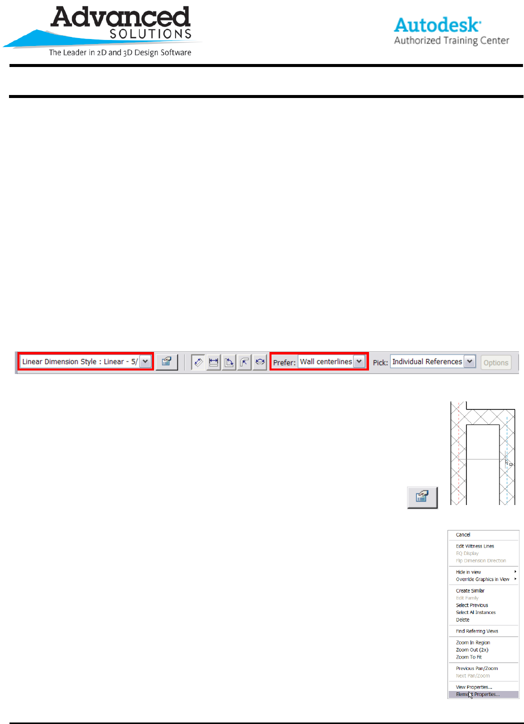
1. Start by selecting the dimension tool on the design bar. If you have already created centerline dimension style
or any other dimension style, it can be selected from the type selector on the Options Bar. The most important
option on the Options Bar is the Prefer setting. Make sure it is set to “Wall centerlines” to select the walls
centerline when hovering over it (Figure 1).
Note: If the Prefer option is not selected at this point, you can hover over the center of the object and press the
tab button to cycle through the various parts of the object.
Figure 1
2. When hovering over the walls, notice that a blue dashed line represents the center of the
wall (Figure 2). This makes it easy to select that part of the wall. It is also worth noting that the
centerline option in the dimension properties will not work unless the center of the wall is
selected. You can purposely set the dimension string up so that certain parts take advantage
of the centerlines and some do not.
3. After the dimension string has been placed, select it and go to the element
properties on the options bar (Figure 3) or by right clicking (Figure 4).
Figure 3 Figure 2
Figure 4
www.advsolinc.com
ASI Client Center
1-877-438-2741
Autodesk Products Tip & Tricks
Copyright 2008 – Advanced Solutions, Inc.
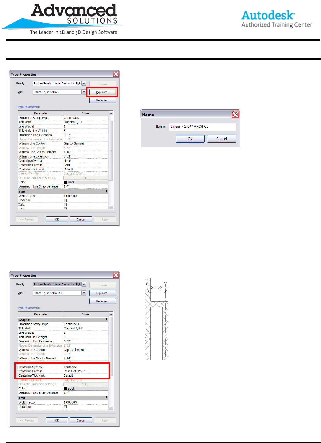
4. In the Type Properties Dialog Click on Duplicate to make a copy to
be used for changes (Figure 5). Be sure to give the new dimension
style a unique name (Figure 6).
Figure 6
Figure 5
5. The three options that control how the centerline dimension string looks are “Centerline Symbol”, “Centerline
Pattern” and “Centerline Tick Mark” (Figure 7). After selecting the options in Figure 7, the Dimension String has a
CL symbol and dashed extension lines (Figure 8)
Figure 8
Figure 7
