How To Use Position Representations In Inventor 063009
2016-06-08
: Guides 063009 Howtousepositionrepresentationsininventor 063009_HowToUsePositionRepresentationsInInventor tips pdf asi
Open the PDF directly: View PDF ![]() .
.
Page Count: 2
www.advsolinc.com
ASI Client Center
1-877-438-2741
Autodesk Products Tip & Tricks
Copyright 2008 – Advanced Solutions, Inc.
Product: Autodesk Inventor 2009
Topic: How to use Position Representations in Inventor
Written by: Paul Cetnar, Application Engineer, Manufacturing Solutions Division
Date: June 30, 2009
Hello, and welcome to another edition of our Tips & Tricks.
During our discussion today, we’ll be taking a look at the benefit of incorporating Position Representations in
Inventor and how to set them up. What these do is allow users to portray components in an assembly at
varying angles which can be pre-determined and accessed by performing a simple double click.
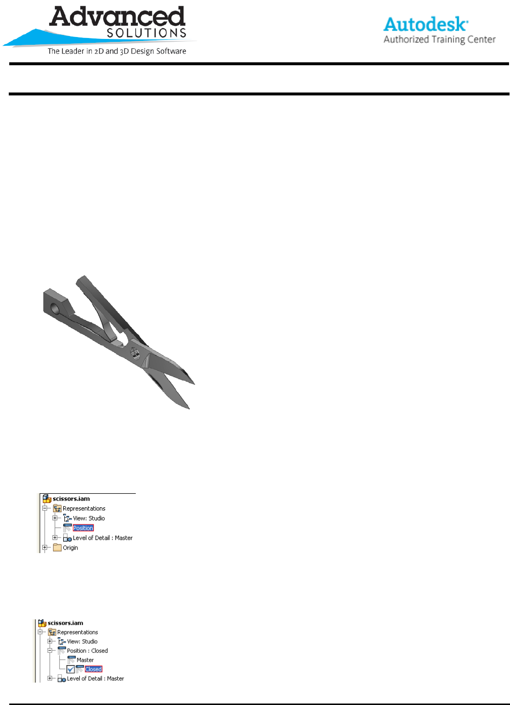
To begin, let’s take a look at the assembly I’ll be using to demonstrate this process, see Figure 1.
Figure 1
Now looking at the assembly, maybe we want to illustrate how the scissors look in the closed position as well,
This is where a position representation comes into play. To set this up, we are going to access some options
in the model browser of our assembly file. The options are under the Representations folderÆ’Position:’ See
Figure 2.
Figure 2
From here, we are simply going to right click on the ‘Position’ heading and select ‘New’. Once we do this,
we’ll see a new item created at the bottom labeled Position1 (which I highly recommend renaming to
something more specific). For mine, I’ll call it ‘Closed’ to go with the closed state we’ll create. See Figure 3.
Figure 3
www.advsolinc.com
ASI Client Center
1-877-438-2741
Autodesk Products Tip & Tricks
Copyright 2008 – Advanced Solutions, Inc.
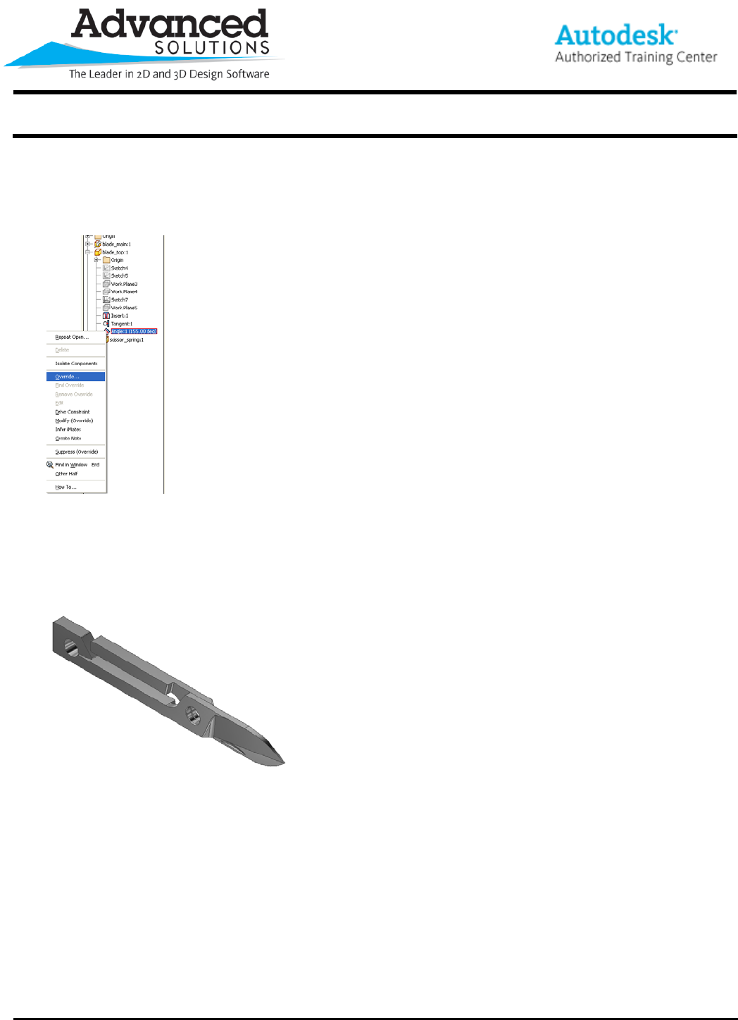
With our ‘Closed’ position representation active, all we have to do is override the current angle set in the
angular constraint within our assembly. To do this, simply highlight the appropriate driving angular constraint
in the model browserÆRight ClickÆOverride. See Figure 4 for the flyout options.
Figure 4
At this point, we’re presented with our ‘override’ dialogue box at which point we’ll need to toggle on the ‘Value’
option and input our desired angle. Since I want this to be closed, I’ll enter in 180 degrees. After doing so,
we’ll see the scissors close into our desired position. Furthermore, we have the ability to double click
between our different positions representations whenever we like. See Figure 5 for our closed position.
Figure 5
Thanks again for reading this edition of our tips and tricks. I hope this helps provide some insight on how to
present your assemblies.
