Simplify Multiple Sketches 063009 Creating
2016-06-08
: Guides 063009 Simplifycreatingmultiplesketches 063009_SimplifyCreatingMultipleSketches tips pdf asi
Open the PDF directly: View PDF ![]() .
.
Page Count: 2
www.advsolinc.com
ASI Client Center
1-877-438-2741
Autodesk Products Tip & Tricks
Copyright 2008 – Advanced Solutions, Inc.
Product: AutoCAD Inventor 2010
Topic: Simplify Creating Multiple Sketches
Written by: Hal Carruthers, Sr. Technical Engineer
Date: June 30, 2009
When starting a new job or project, one of the first steps for many of us is to create a 2D or 3D layout to represent
the overall envelope of the design or key locations of static components. During this stage, we create several 2D
sketches in differing orientations or elevations. The traditional workflow for establishing the orientation and
position of our 2D sketches involves setting up work planes prior to creating the 2D sketch. This process can be
time consuming and edits to the location and orientation of the work planes may be difficult or confusing later in
the design.
Another approach is to surfaces is to quickly establish planes for 2D sketches or edges for use in 3D sketch.
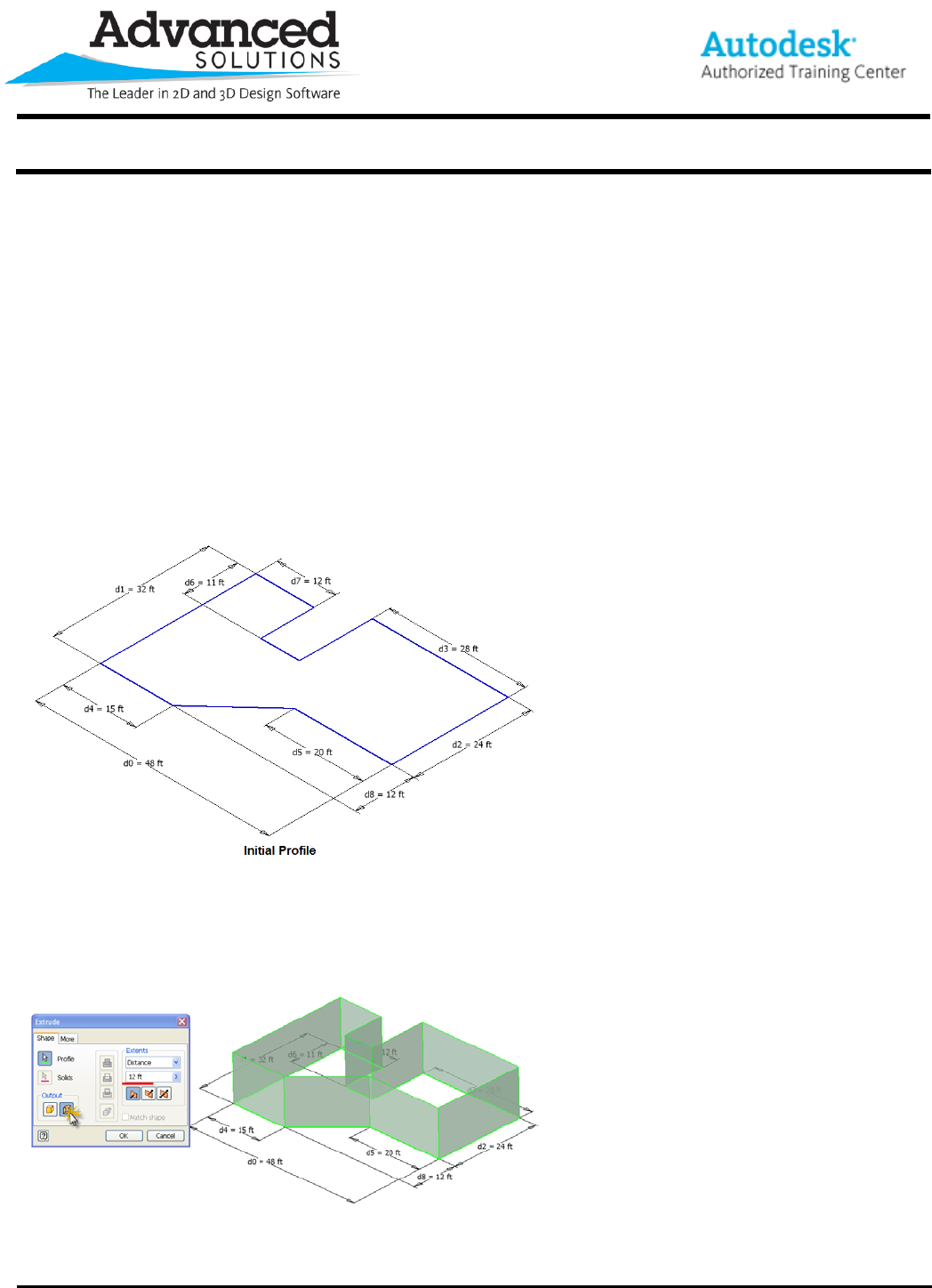
Step 1. Establish a 2D profile to locate and orientate your future sketch planes. (Plan view orientation)
Step 2. Extrude profile as a surface to the top elevation.
1. Set the Output to “Surface.”
2. Select the profile geometry.
3. Enter the Distance.
4. Click Ok.
www.advsolinc.com
ASI Client Center
1-877-438-2741
Autodesk Products Tip & Tricks
Copyright 2008 – Advanced Solutions, Inc.
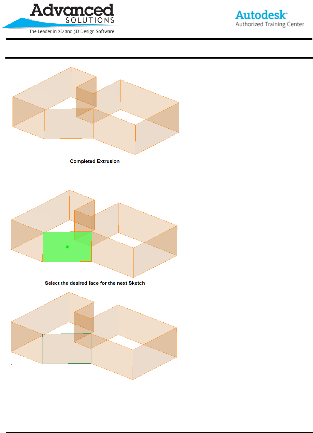
Step 3. Select surface faces for elevation sketches.
You now have multiple faces available for creating Sketches. Editing the location of the faces and planes is now
a simple matter of editing the dimensions of original profile sketch. This technique can very useful for creating
Skeleton models or when preparing data for use with the Frame Generator.
