Grade To A Set % For Rectangular Areas 122608 Percentage
2016-06-08
: Guides 122608 Gradetosetpercentage 122608_GradeToSetPercentage tips pdf asi
Open the PDF directly: View PDF ![]() .
.
Page Count: 3
www.advsolinc.com
ASI Client Center
1-877-438-2741
Autodesk Products Tip & Tricks
Copyright 2008 – Advanced Solutions, Inc.
Product: AutoCAD Civil 3D 2009
Topic: Grade to a set % for rectangular areas
Written by: Scott Underwood, PE, Technical Engineer
Date: December 26, 2008
You can use this tip to apply a grading at a set grade to form a cap with grading object.
This is useful for applying a cap at a set grade on a temporary storage pile of material or on a landfill. You could
use the same method to grade a pond or basin with a bottom at a set grade and works equally well using slopes.
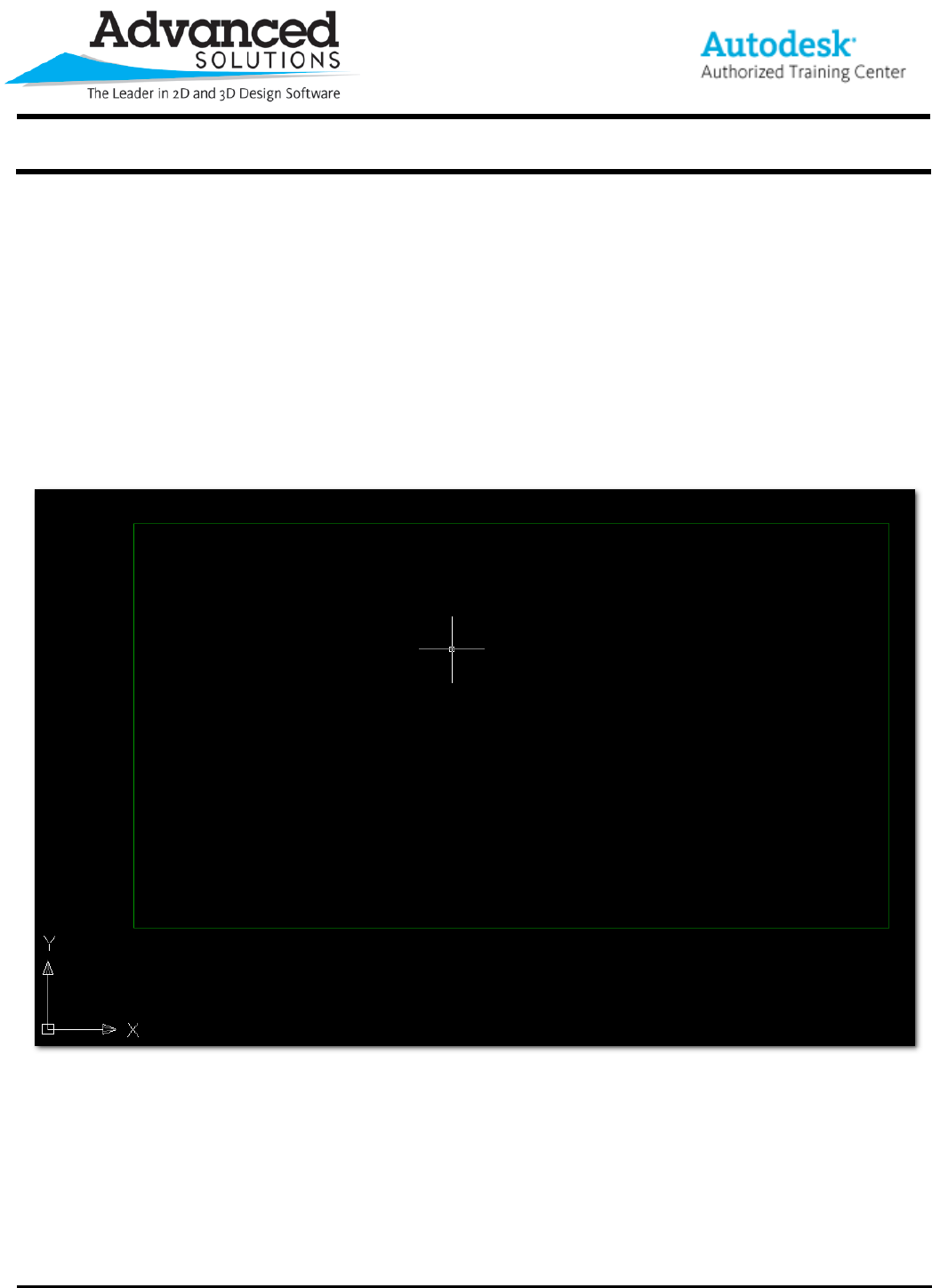
To see how this tip works start by drawing an AutoCAD rectangle and converting it to a feature line. See Figure
1.
Figure 1
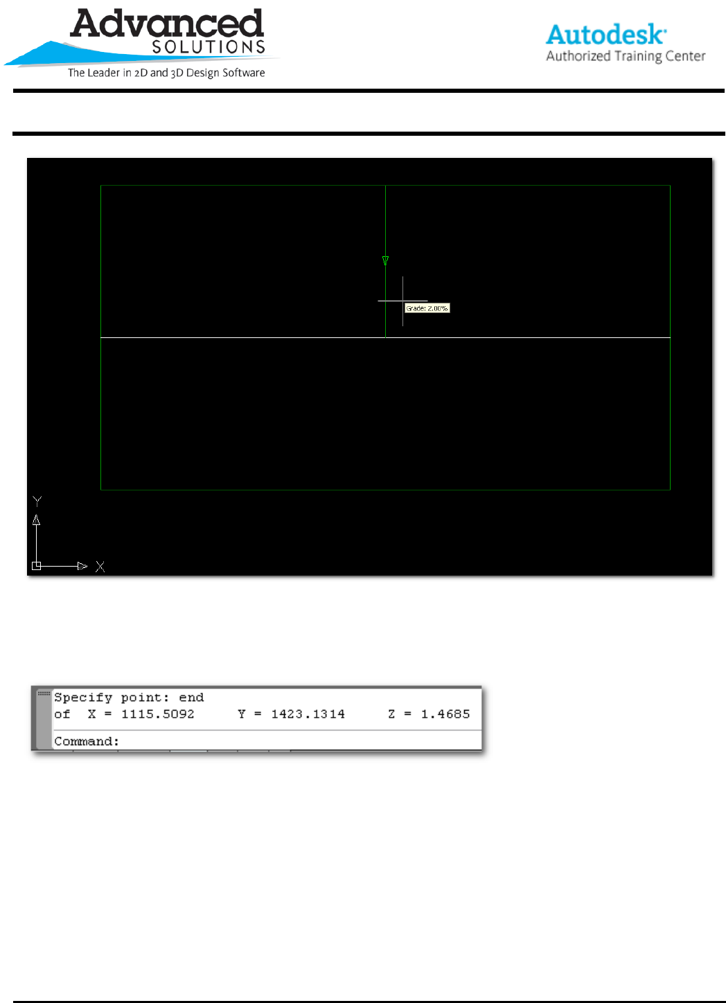
Next, we need to determine the elevation that the grading should target to hold your slope requirement. Draw a
feature line from the midpoint of the longest side of the rectangle to the middle of the rectangle at the slope or
grade you want to hold. The white line is a temporary AutoCAD line to find the middle of the rectangle. See
Figure 2.
www.advsolinc.com
ASI Client Center
1-877-438-2741
Autodesk Products Tip & Tricks
Copyright 2008 – Advanced Solutions, Inc.
Figure 2
We need to cut and paste the elevation of the feature line at the middle of the rectangle. Type ID <Enter> at the
command prompt, then using your endpoint OSNAP select the end of the feature line at the middle of the
rectangle. The elevation will show as the Z coordinate at the command prompt. See figure 3.
Figure 3
Simple use your cursor and highlight the elevation, right click and select copy. The value is now stored on the
windows clipboard for later use.
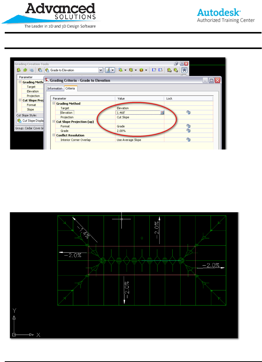
Now delete the temporary white AutoCAD line and let’s move on to creating the grading. Start the grading
command using the Grading menu and selecting Create Grading. When the Grading Creation Tools dialog
opens change the grading criteria to Grade by Elevation. Edit these criteria by clicking the edit icon just to the
right of the dropdown where you selected Grade by Elevation. Make the changes show in Figure 4.
www.advsolinc.com
ASI Client Center
1-877-438-2741
Autodesk Products Tip & Tricks
Copyright 2008 – Advanced Solutions, Inc.
Figure 4
Then select OK.
Now set the grading group to the same as your perimeter feature line created from the AutoCAD rectangle, create
a grading group and then apply your grading. Select the perimeter feature line, click to the inside. Hit enter
through the values you setup in the criteria.
Now you have created a cap using a grading with a slope of 2%. Here’s a view of the grading with the slopes
labeled. See Figure 5.
Figure 5
Keep in mind you can use this for ponds and basins as well.
