Advance Steel 2017 Getting Started Guidel
2016-04-12
: Guides Advance-Steel-2017-Getting-Started-Guidel Advance-Steel-2017-Getting-Started-Guidel products pdf ds
Open the PDF directly: View PDF ![]() .
.
Page Count: 55
Starting Guide

ADVANCE STEEL Starting Guide
2
TABLE OF CONTENTS
INTRODUCTION .................................................................................................................................4
Advance Steel ............................................................................................................................................ 4
Where to find information? ...................................................................................................................... 5
INSTALLATION ...................................................................................................................................5
System requirements ................................................................................................................................ 5
Starting the installation............................................................................................................................. 5
STARTING ADVANCE STEEL .................................................................................................................6
ADVANCE STEEL USER INTERFACE .......................................................................................................6
Other important tools for using Advance ................................................................................................. 7
Advance Steel UCS .................................................................................................................................... 8
Accessing Element Properties ................................................................................................................... 8
3D MODELING ...................................................................................................................................9
Advance objects ........................................................................................................................................ 9
Creating a building grid ......................................................................................................................... 9
Creating columns ................................................................................................................................ 12
Creating beams ................................................................................................................................... 14
Straight beams .................................................................................................................................... 14
Automatic Steel Connections .................................................................................................................. 16
Accessing joint properties ................................................................................................................... 18
Creating a Clip Angle connection ........................................................................................................ 18
Copying a connection .......................................................................................................................... 19
Shear plate connection ....................................................................................................................... 22
Creating a base plate .......................................................................................................................... 23
Creating a bracing ............................................................................................................................... 25
Inserting a hand-railing ....................................................................................................................... 27
Inserting Straight stairs ....................................................................................................................... 28
Inserting isolated footing .................................................................................................................... 29
Clash check .............................................................................................................................................. 30
NUMBERING .................................................................................................................................... 31

ADVANCE STEEL Starting Guide
3
DRAWING CREATION ....................................................................................................................... 32
Drawing management ............................................................................................................................ 41
Opening the Document Manager ....................................................................................................... 41
Create Shop Drawings ............................................................................................................................. 42
LIST CREATION ................................................................................................................................. 47
CNC DATA CREATION ....................................................................................................................... 50
RECOMMENDED PRACTICES ............................................................................................................. 52
Saving the project ................................................................................................................................... 52
Modeling ................................................................................................................................................. 52
Numbering .............................................................................................................................................. 53
Creating drawings ................................................................................................................................... 54
Lists ......................................................................................................................................................... 54
NC files .................................................................................................................................................... 54

ADVANCE STEEL Starting Guide
4
INTRODUCTION
This starting guide is a brief introduction to working with Advance Steel, describing the basic
methodology and not meant to replace formal training.
Advance Steel’s model based environment allows you to produce accurate detailed general
arrangement and shop drawings faster, helping to speed time to erection and fabrication.
The Advance Steel objects chapter describes the main objects to create a small steel structure.
Some of the Advance Steel connections are described in the Automatic Steel Connections chapter and
are used to create a small model. The 3D model is created using a 1:1 scale. The model contains
information about dimensions, objects, and attributes from which drawings are created as described in
the Drawing Creation chapter.
The examples presented in this guide are generic for worldwide use and do not conform to local or
specific company standards.
Since not all Advance Steel tools are described in this guide, refer to the Advance Steel Help for more
details on all commands and parameters.
Advance Steel
Advance Steel is a leading edge steel construction application designed for steel professionals. It
provides a simple user-friendly working environment for creating 3D structural models from which
drawings are created.
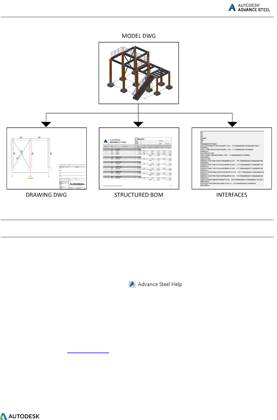
The three dimensional model is created and stored in a drawing (in DWG format). The Advance Steel
model forms the basis of the 3D construction. Complex structures are created using Advance Steel
structural elements (e.g., a stairway) with all the required features, joints, and connections, within a
command.
The Advance Steel model becomes the master reference for other tools:
Dimensioned and labeled general arrangement and shop drawings are automatically created
from the model.
The Advance Document Manager manages all general arrangement and shop drawings. The
update tool in the Document Manager makes single click drawing adjustments possible after
model changes.
Structured BOMs (bills of materials) and NC-information are also created from the model and
include all model information such as part marks and quantities. The Document Manager also
controls these documents.
ADVANCE STEEL Starting Guide
5
All software tools described in this guide and all remarks related to the product pertain only to Advance
Steel and for reading simplification only the generic name Advance is used.
Where to find information?
Advance has a help system that offers step-by-step instructions for every function.
To access the help:
Go to the Tools tab > Tools panel > click
INSTALLATION
System requirements
To successfully install Advance Steel, certain requirements have to be met.
For more details, see the Installation help.
Starting the installation
Before installing Advance Steel 2017:
- Make sure you have Autodesk AutoCAD® 2017 installed on your computer.
- Make sure you have administrator rights.
ADVANCE STEEL Starting Guide
6
- Close all active Windows applications.
- Disable the antivirus.
STARTING ADVANCE STEEL
To start Advance Steel:
- Double click on the Advance Steel icon on the desktop.
Or
- On the Windows task bar, click , then select All programs > Autodesk > Advance Steel 2017 >
Advance Steel 2017
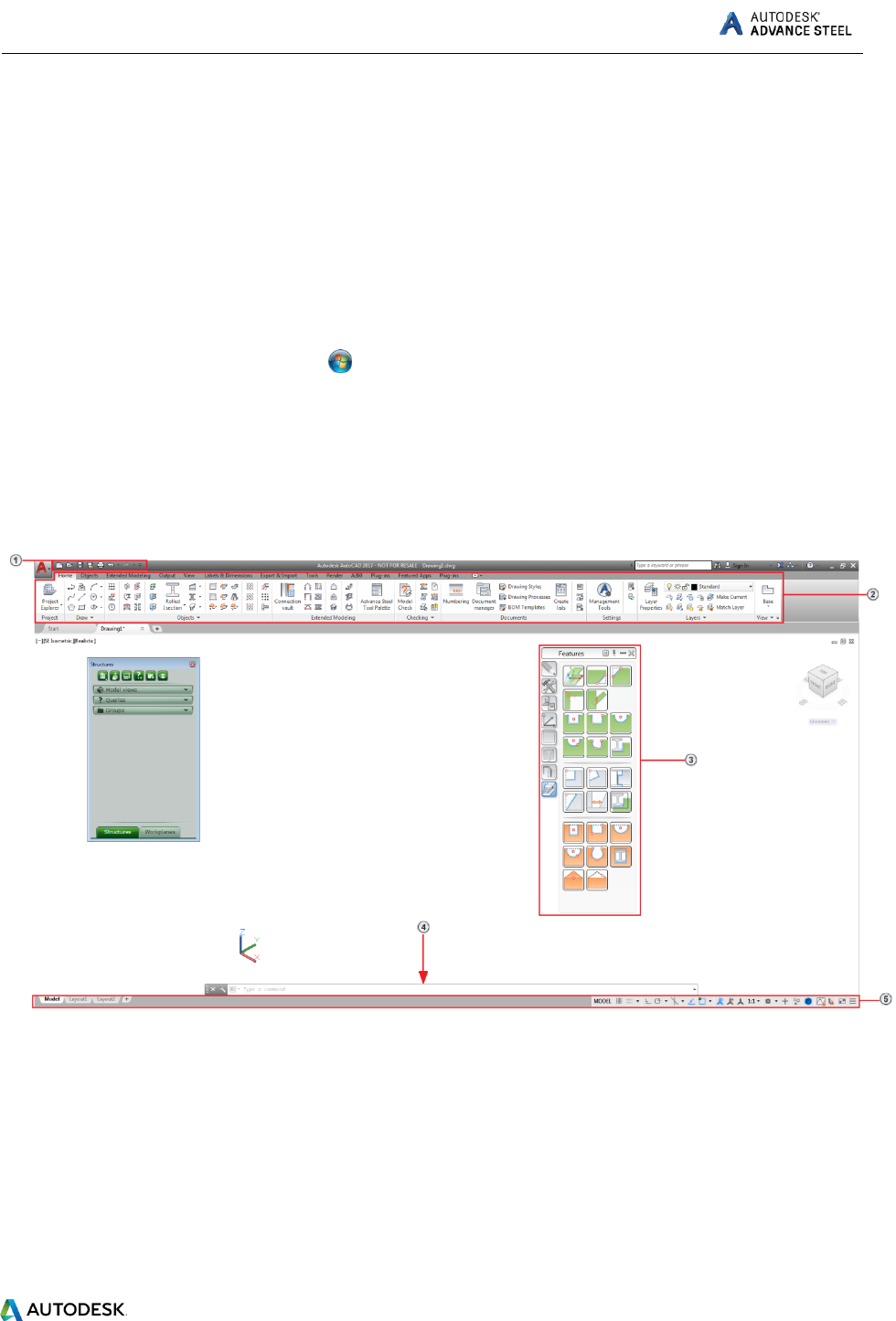
ADVANCE STEEL USER INTERFACE
Advance Steel is fully integrated into AutoCAD®. Advance Steel panels are added to the AutoCAD®
ribbon.
1. The Quick Access Toolbar
Provides fast access to the most frequently used tools. To add an Advance Steel tool to the
Quick Access Toolbar, right-click the ribbon button and select Add to Quick Access Toolbar.
The Quick Access Toolbar can be positioned above or below the ribbon.
2. The ribbon
Contains a collection of panels grouped on tabs, according to type. For easier access, the main
tools are located on the Home tab. On the panels, tools are grouped on different rows and
include large buttons for the most frequently used functionalities.
ADVANCE STEEL Starting Guide
7
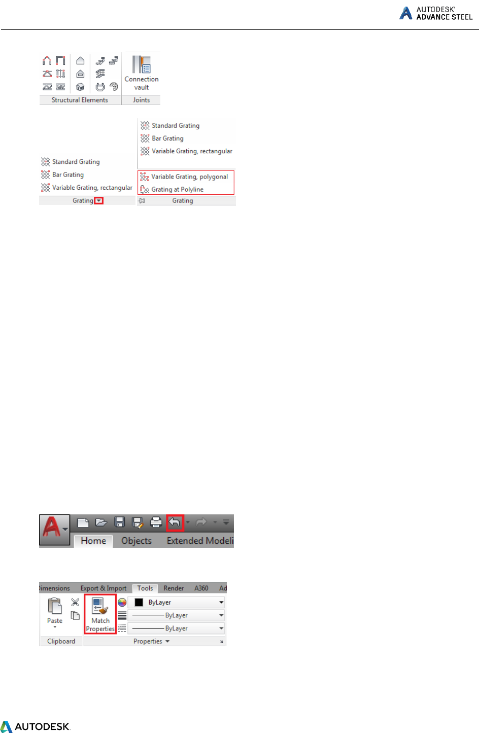
Some panels can be expanded by clicking the arrow on the bottom line.
The ribbon can be minimized, thus enlarging the drawing area.
3. Tool palettes
Contain other tools, complementary to the functionalities available on the Advance Steel ribbon.
4. Command line
Allows Advance Steel commands to be entered using the keyboard. Press <Enter> after each
entry.
5. Status bar
Displays information regarding the program status during different phases of the project. It also
provides access to the configuration of certain parameters: snap modes, object tooltips content,
current coordinate system, and working units.
Other important tools for using Advance
To cancel a command, press the Esc key.
The current command and prompts are displayed in the command line window at the bottom of
the screen. Press the F2 key to open and close the command line window.
The right mouse click behaves like the Enter key.
When the cursor hovers over a ribbon button, the button's tooltip appears.
The Undo command on the Quick access toolbar cancels one or several commands.
The Match properties command copies properties from one object to another. The transferred
properties are selected from the given list.
ADVANCE STEEL Starting Guide
8
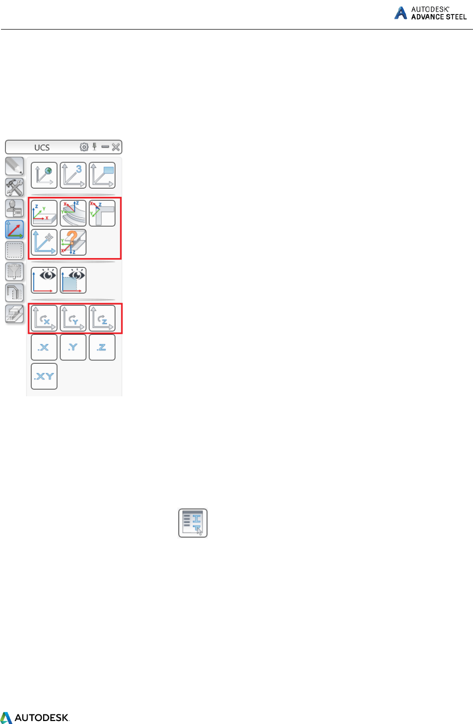
Advance Steel UCS
Advance Steel objects are created in 3D-space using the appropriate tools and their orientation is
dependent on the current User Coordinate System (UCS). To place the coordinate systems in the correct
position use the Advance Steel UCS tool palette.
Accessing Element Properties
When you create an Advance Steel element, a dialog appears, in which different settings and drawing
styles can be changed.
There are several ways to access the element properties:
On the Tools tool palette, click .
Right-click the element and select Advance Properties from the context menu.
Double click the element.
ADVANCE STEEL Starting Guide
9
3D MODELING
Advance objects
Advance objects are created in 3D-space using various program tools. The object’s orientation depends
on the current UCS (User Coordinate System).
Creating a building grid
The grid is useful for placing construction elements and for orientation in the 3D view. Placing grid axes
is the first step of 3D modeling in Advance.
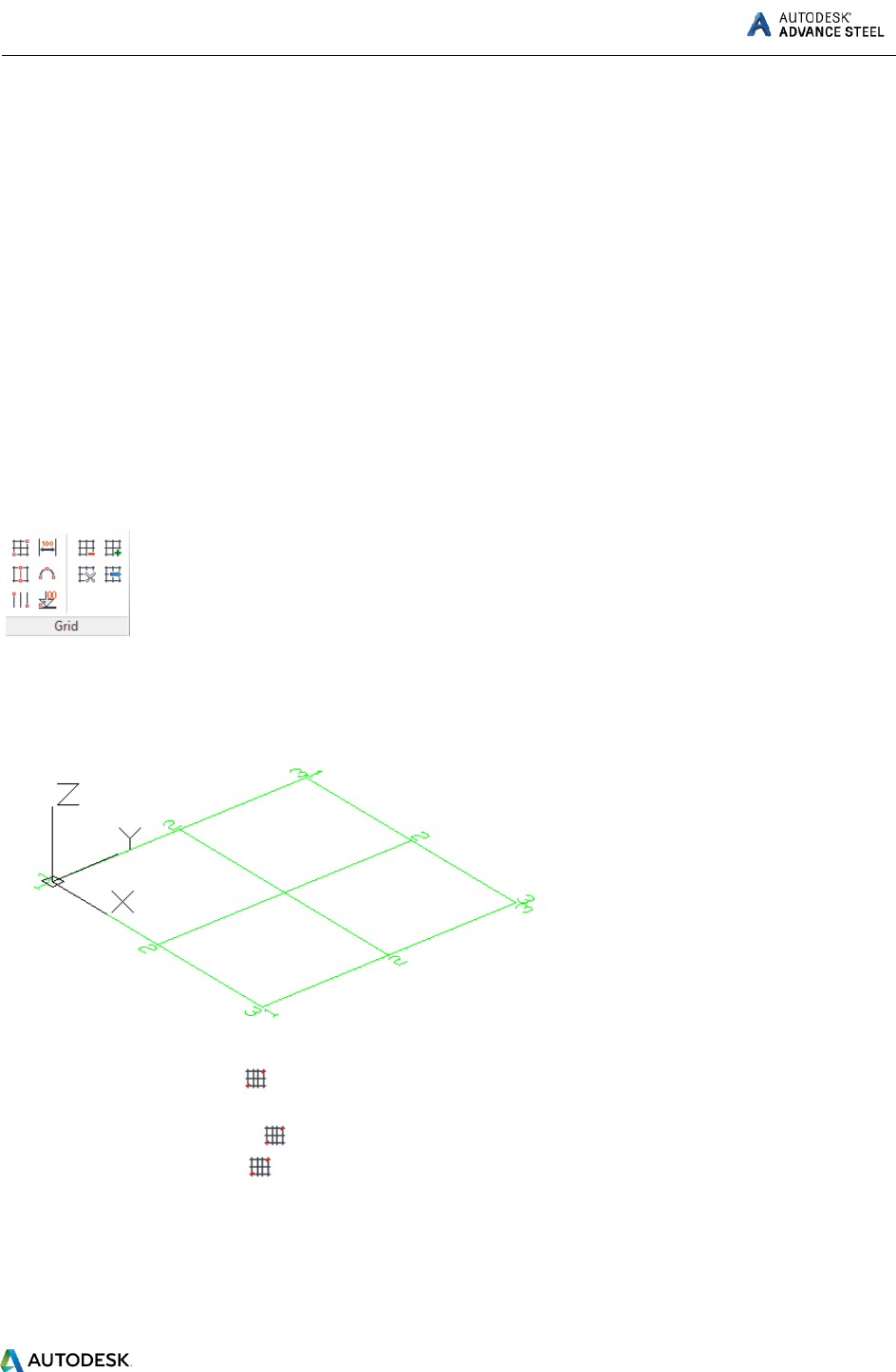
A building grid is created in the X/Y-plane of the current coordinate system and consists of two
independent axis groups: in the X- and Y- directions. The grid axis tools are grouped on the Grid panel of
the Objects tab.
Example: Building grid with 3 axes in the X-direction and in the Y-direction:
1. On the ribbon, click (Building Grid).
Home > Objects > (Building grid)
Objects > Grid > (Building grid)
2. Enter 0”, 0”, 0” on the command line to set the first point in the origin.
3. Enter 196”, 196” to set the second point.
Next, modify the axes number in each group.
ADVANCE STEEL Starting Guide
10
1. Select the X-axis group.
2. Right click and select Advance Properties from the context menu. The Axes parallel dialog box
appears. All modifications are made here.
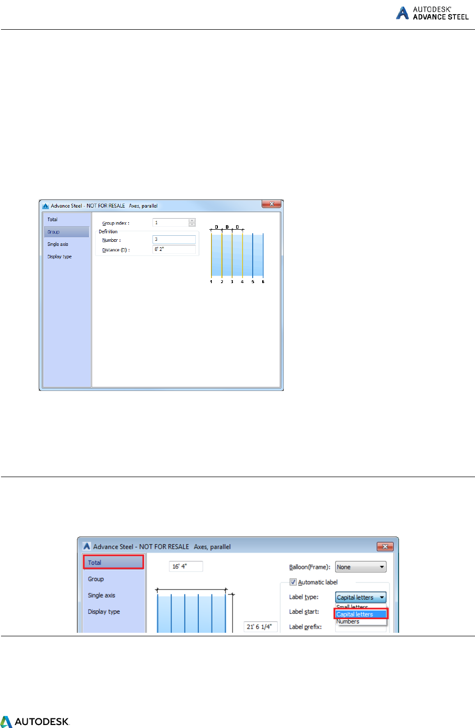
To modify the number of axes:
1. Click the Group tab.
2. Set the Number to 3. Note that the distance value is automatically calculated. The new value
should be 8' 2".
The model changes dynamically as values are entered or new values are selected, providing instant
visual feedback.
Repeat the same steps for the axes in the Y-direction.
Note: You can also change the label type to capital letters for the axes in the Y direction, for more clarity.
You can do this by accessing the Total tab in the Axes, parallel dialog, and choosing “Capital letters”
from the Label type drop-down.
ADVANCE STEEL Starting Guide
11
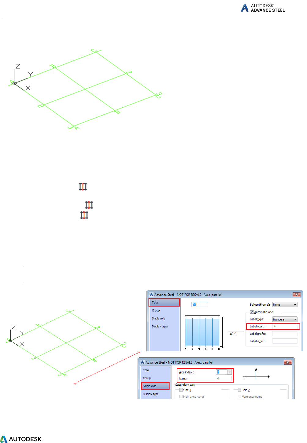
Example: Adding an axis to the grid.
To add a single axis:
1. On the ribbon, click (Single axis).
Home > Objects > (Single axis).
Objects > Grid > (Single axis).
2. Click where you want to add the axis and enter 0” on the command line to set the first point in
the origin.
3. Enter 196” to set the second point. The Axes, parallel dialog appears:
4. In the Total tab, set the Label start to 4, to rename the axis index.
Note: You will see that in the Single axis tab, the Axis index and Name will be automatically set
to 4.
Next, extend the grid (the axis group created in the Y direction) to reach the newly created axis.
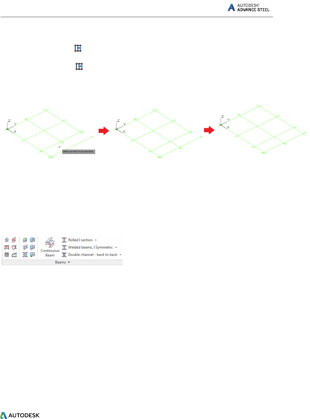
ADVANCE STEEL Starting Guide
12
To extend an axis group:
1. On the ribbon, click (Extend axes).
Objects > Grid > (Extend axes).
2. Select the boundary object, which in this case is the axis labeled with 4 and press Enter.
3. Next, select the axes that need to be extended (axes A, B and C), one by one, pressing Enter
after each selection:
Creating columns
Columns are created directly in the model and are displayed, by default, in the Wireframe mode.
Columns are created as simple sections, compound sections, curved sections or welded sections. The
column creation is performed using the Column command on the Beams panel, Objects tab.
The command can also be found in the Objects panel, on the Home tab.
Columns are simply placed in the model. You can place as many columns as you need. To exit the
command press the Esc or Enter keys or right-click your mouse.
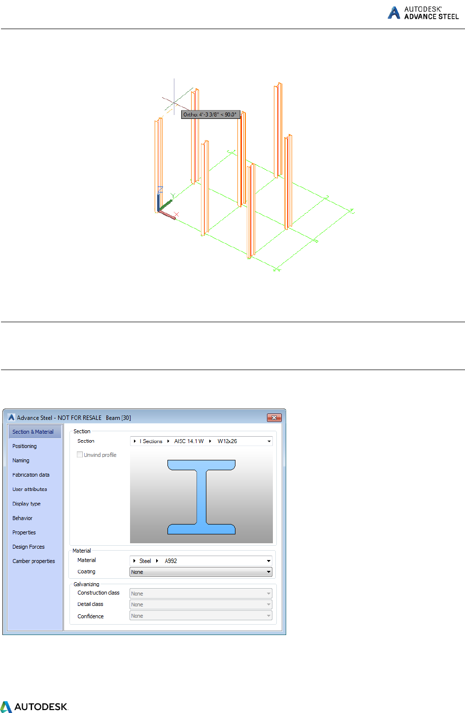
Example: Creating W12x26 columns.
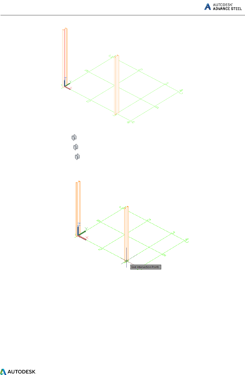
ADVANCE STEEL Starting Guide
13
.
1. On the ribbon, select
Home > Objects >
Objects > Beams >
2. Place the columns where you need in the model. In this example they are placed at the grid
intersections.
3. Right-click your mouse to exit the command.
The Beam dialog box appears. Select the section class (AISC 14.1 W), followed by the section (W14x48).
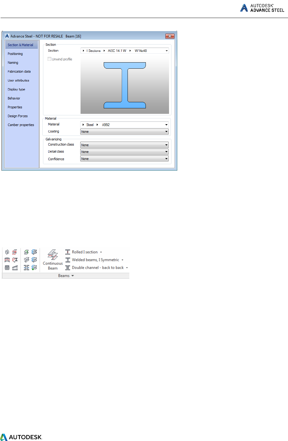
ADVANCE STEEL Starting Guide
14
Creating beams
Beams are created directly in the model and are displayed, by default, in the Wireframe mode.
In Advance, a variety of different beam types are available. Beams are created as simple sections,
compound sections, curved sections or welded sections. The beam creation is performed using the tools
on the Beams panel, Objects tab.
The most used beam creation tools are grouped on the Objects panel, on the Home tab.
Straight beams
Example: Creating W12x26 straight beams from the top of one column to another.
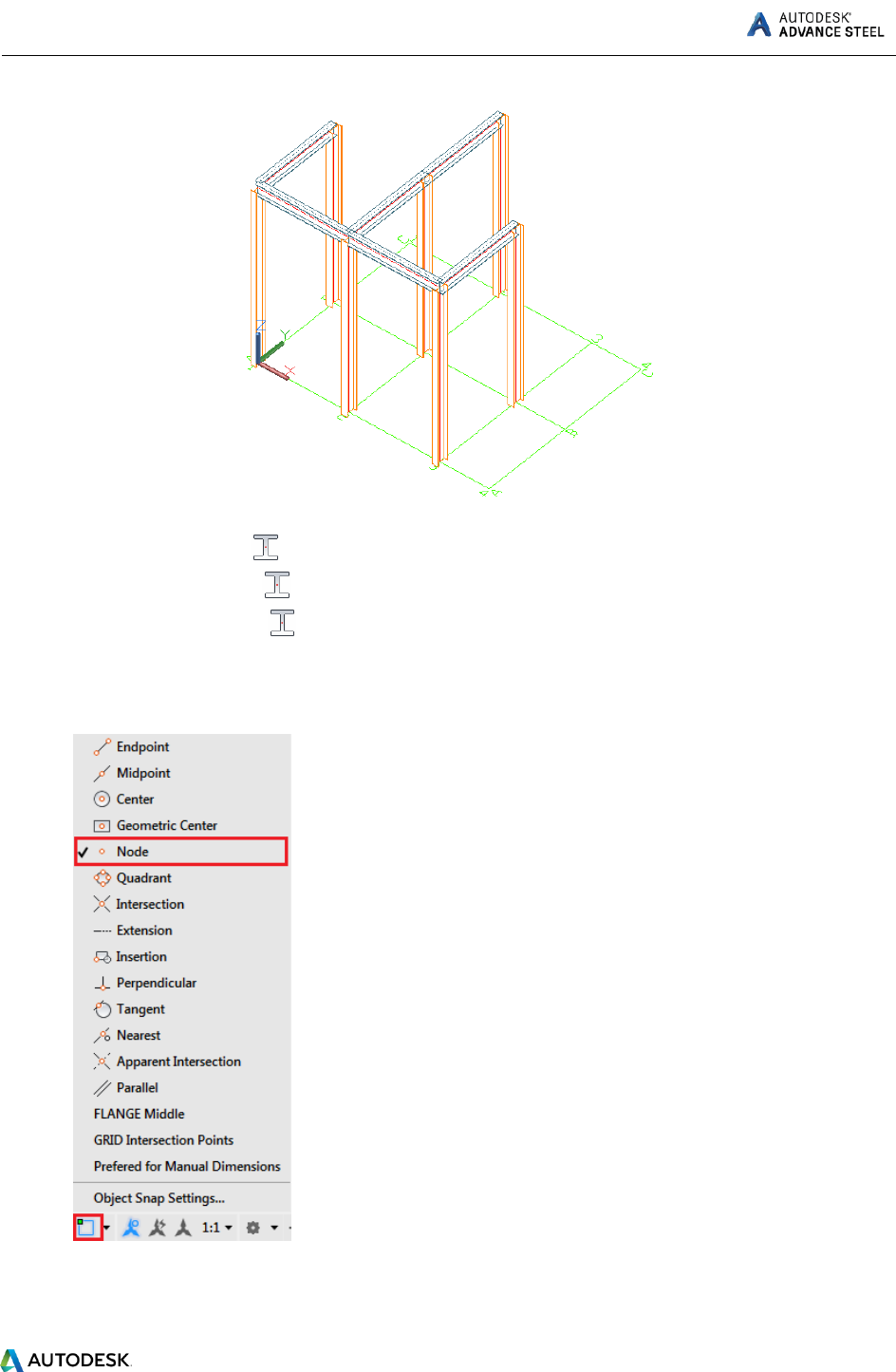
ADVANCE STEEL Starting Guide
15
1. On the ribbon, select .
Home > Objects >
Objects > Beams >
2. Select a Node snap point on the top of the first column.
Note: Make sure the Node option is checked in the Object Snap menu.
3. Move the mouse pointer to the second column top.
ADVANCE STEEL Starting Guide
16
4. Repeat the same steps for as many beams as you want to create and then press Enter to exit the
command.
Note: For a continuous beam creation, use the Continuous Beam command from the Objects tab, Beams
panel. Unlike the other beam creation commands, this one lets you select points continuously, not only
creating objects defined by two points, one by one.
The Beam dialog box appears. Select the section class (AISC 14.1 W), followed by the section (W12x26).
Automatic Steel Connections
Advance Steel helps you improve productivity by providing a parametric library of steel connections.
ADVANCE STEEL Starting Guide
17
All individual joint elements, including their properties, are held together and represented as a gray box
connection object.
Note: A structural element creates several Advance objects at a time (i.e., entire structures are created
by simply clicking one button).
All parts of a structural element are related to each other and their height, position, section, etc., are
changed in one step.
Joints are available in the Connection Vault, which is accessible from the Extended Modeling panel
of the Home tab. The joints are grouped in categories according to the type of individual members.
Frequently used joints can be grouped in the Favorites category for quicker access.

ADVANCE STEEL Starting Guide
18
Accessing joint properties
To access the joint properties dialog:
Double click on the connection object (the gray box).
Select a joint element, right-click and Select Advance Joint Properties from the context menu.
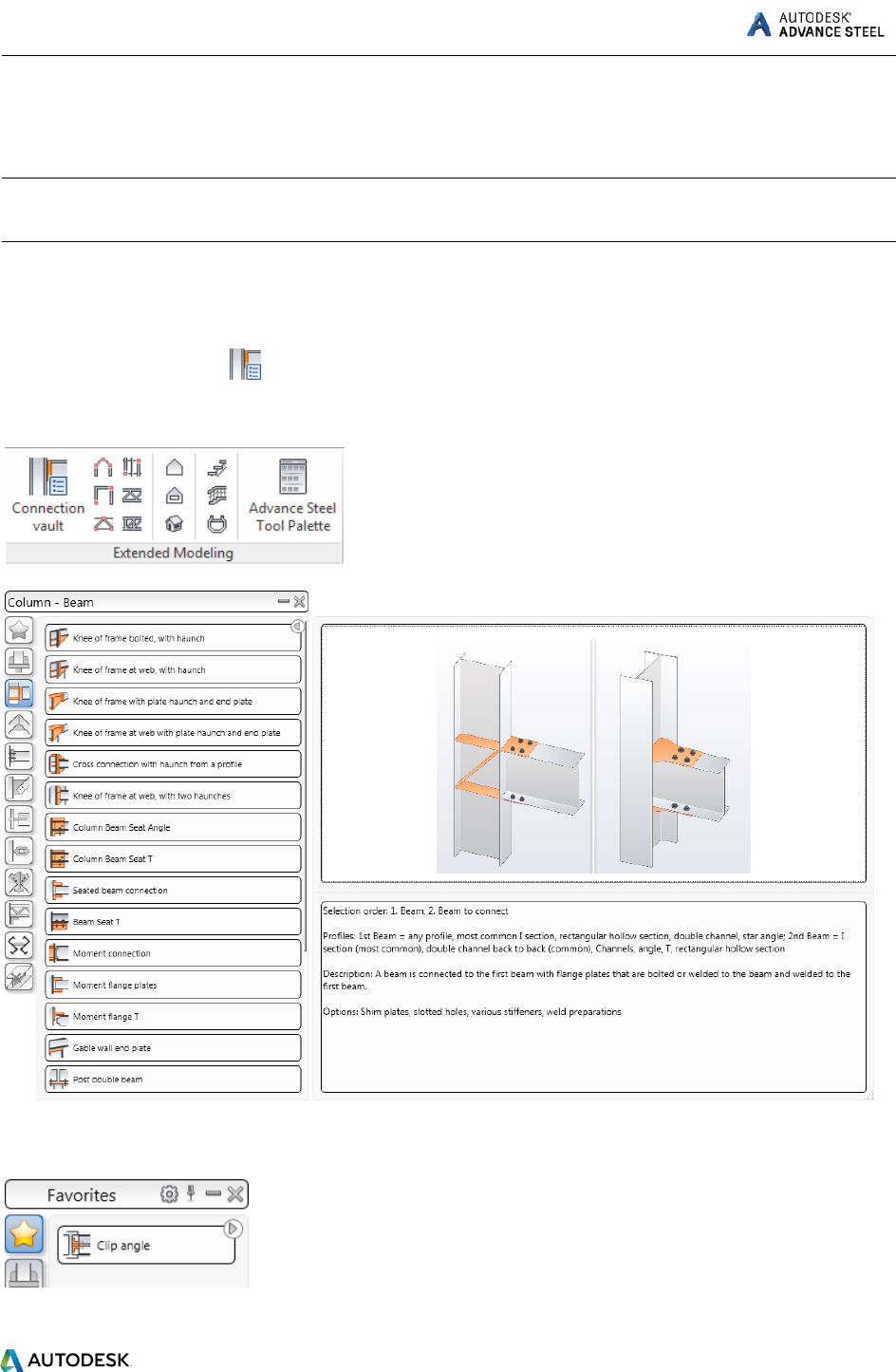
Creating a Clip Angle connection
The clip angle connects a beam to a column using an angle profile.
The tools for clip angle connections are grouped in the Column - Beam category of the Connection
vault.
Example: Creating a clip angle connection.
ADVANCE STEEL Starting Guide
19
1. On the ribbon, click (Connection Vault).
Home > Extended Modeling > (Connection Vault)
Extended Modeling > Joints > (Connection Vault)
2. From the Platform Beams category, click .
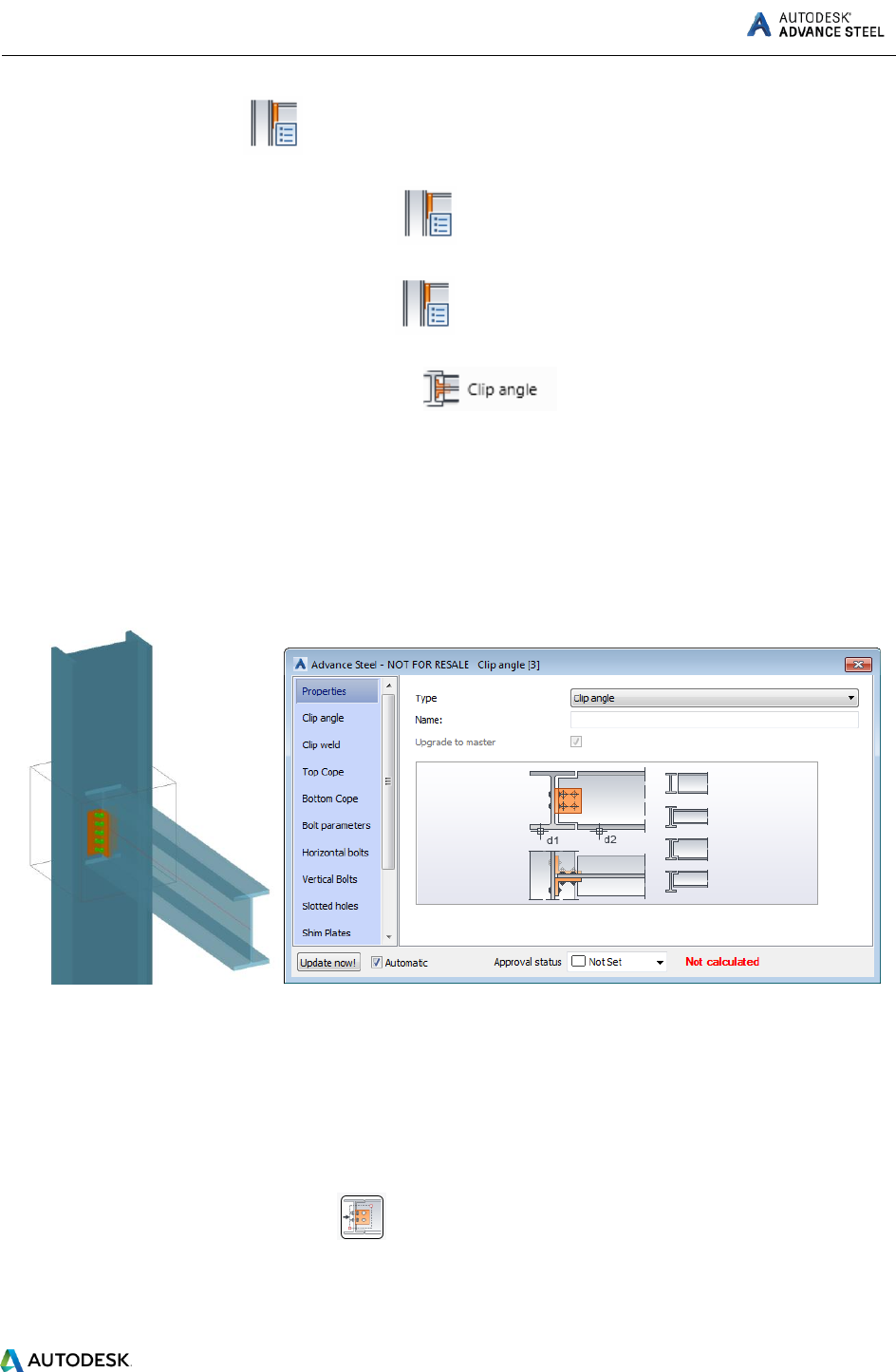
3. Select the column and right click.
4. Select the beam on which the clip angle should be created and right click.
The joint is created and the properties dialog appears. Modify the joint properties to suit specific
requirements.
Copying a connection
Any previously created joint can be used as a template and copied with all its properties.
Example: Copying a clip angle.
1. Select any object created by the clip angle connection to be used as a template.
2. On the Tools tool palette, click (Create by template).
3. Select the destination column and right click.
4. Select the corresponding rafter.
ADVANCE STEEL Starting Guide
20
When a joint is copied, all its properties and logic relations are copied and the values for the joint are
only entered once.
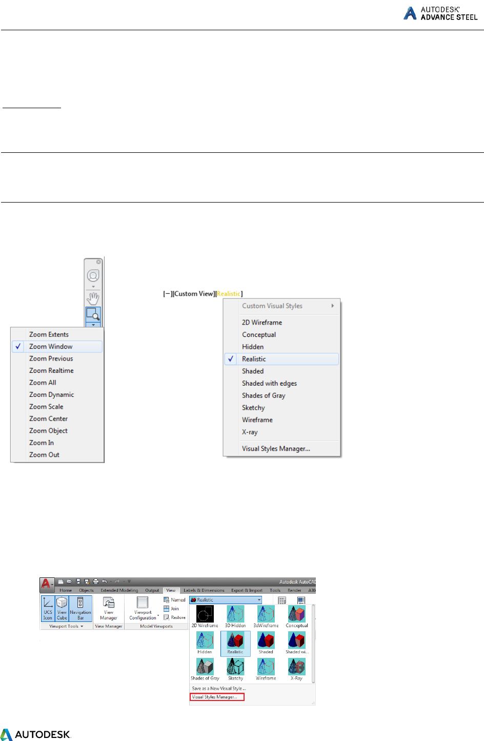
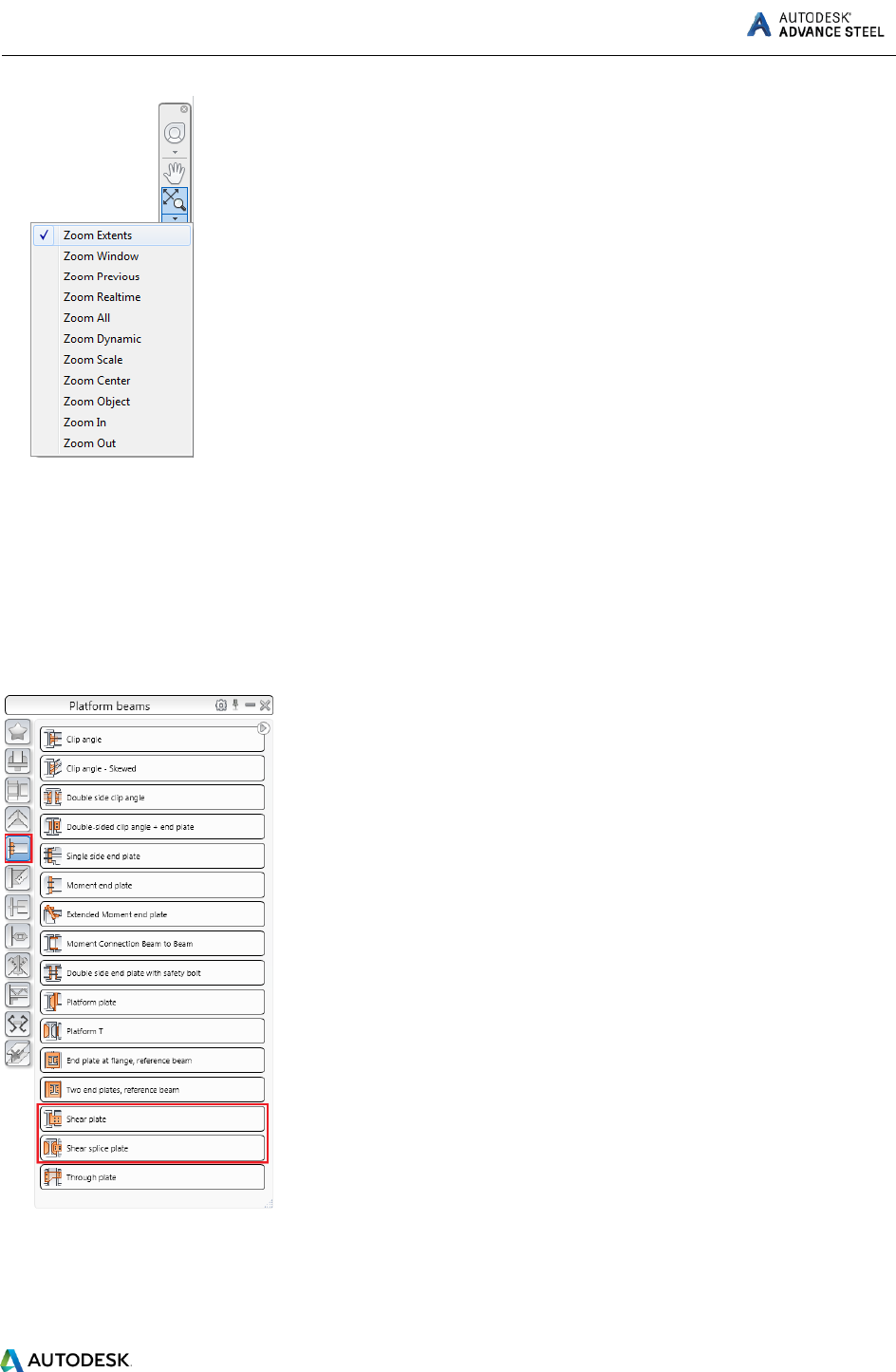
Zoom/Shade
To better view the created connection, use the Zoom window tool.
Note: You can find this tool in the Navigation Bar on the right side of your workspace. If the Navigation
Bar is closed, you can open it, by going to the View tab > Viewport Tools panel and clicking on the
Navigation Bar button.
For a more realistic presentation of the model, use a shaded visual style. From the menus on the top-left
corner of the drawing area select Realistic.
To cancel the shading, return to the 2D Wireframe visual style.
Note: For a cleaner Realistic look, set the Visual Style to not show the Occluded Edges.
To do this:
1. Open the Visual Styles Manager, from the View tab.
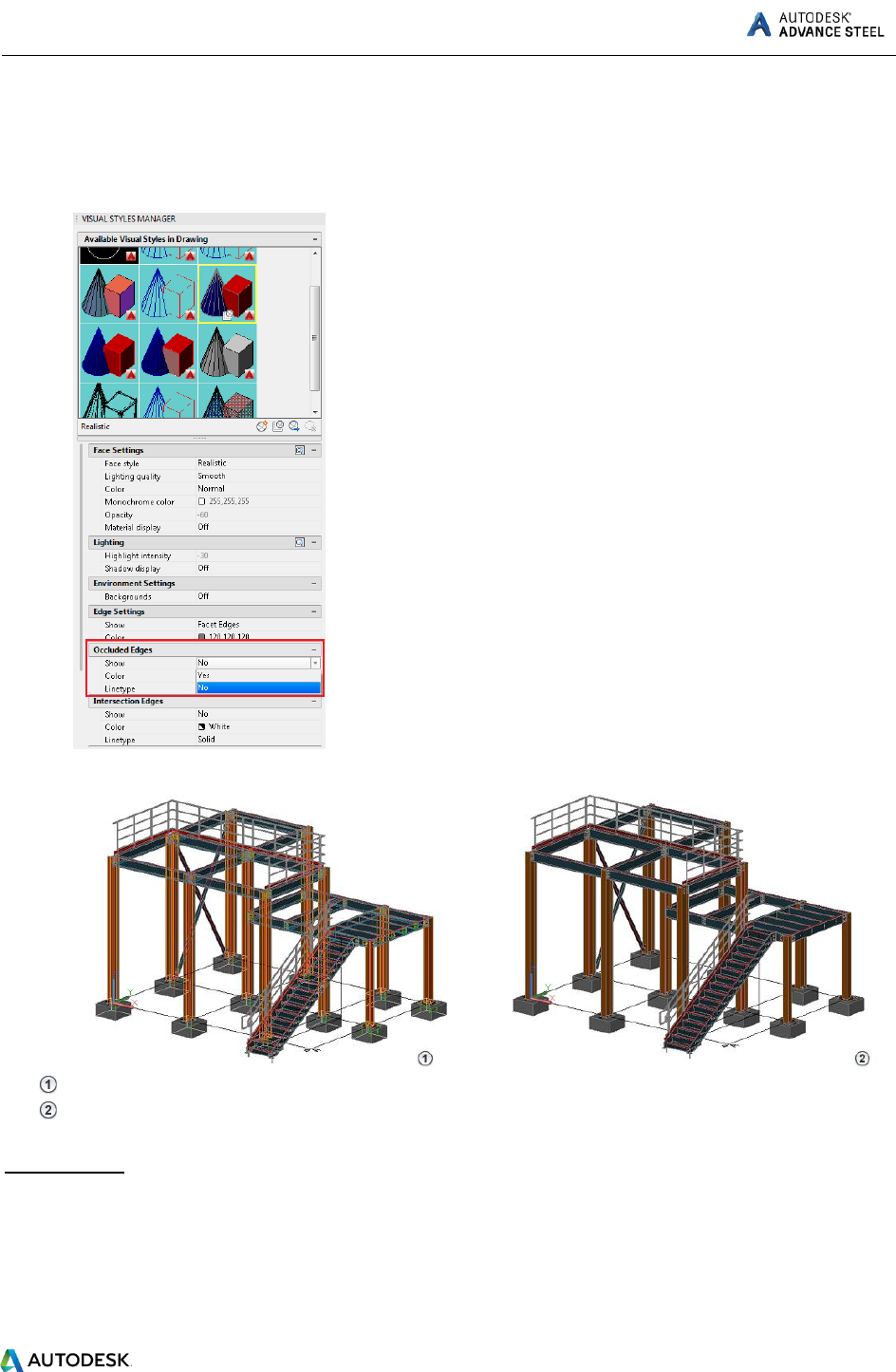
ADVANCE STEEL Starting Guide
21
2. Select the Realistic visual style.
3. In the settings box, go to Occluded Edges and make sure that the Show setting is set to No.
- Occluded Edges on.
- Occluded Edges off.
Cancel Zoom
To view the whole object, use the Zoom Extents tool. The entire frame is displayed.
ADVANCE STEEL Starting Guide
22
Shear plate connection
The shear plate connects a column and a beam, using a single steel plate, welded to the beam and
bolted to the column.
The tools for creating shear plate connections are grouped in the Platform beams category of the
Connection Vault.
Example: Creating a shear plate.
Go to the beams you need to connect.
ADVANCE STEEL Starting Guide
23
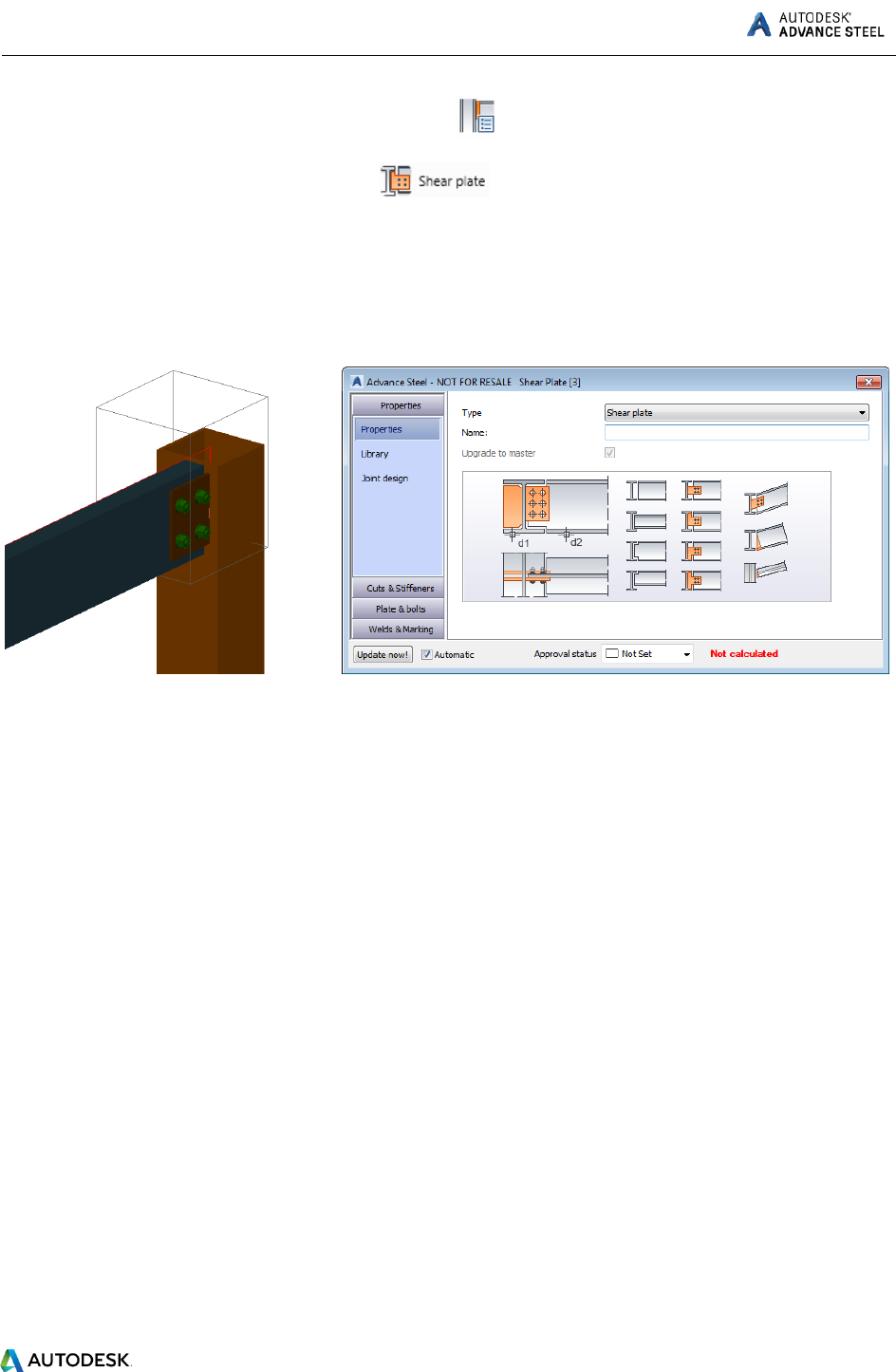
1. On the Home tab, Extended Modeling panel, click .
2. From the Platform beams category, click .
3. Select the column and right click.
4. Select the beam and right click.
The connection is created and can be modified in the properties dialog box.
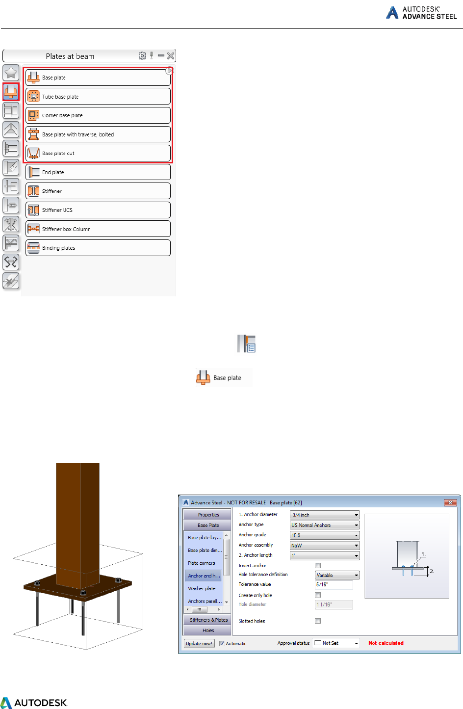
Creating a base plate
In this example, a base plate is created ar the bottom of a column. The column is automatically shotened
by the thickness of the base plate.
The tools for base plate connections are grouped in the Plates at beam category of the Connection
Vault.
ADVANCE STEEL Starting Guide
24
Example: Creating a base plate.
1. On the Home tab, Extended Modeling panel, click .
2. From the Plates at beam category, select .
3. Select the column and right click.
The base plate is created at the end of the column and can be modified in the properties dialog box.
Both the column and the plate are welded together.

ADVANCE STEEL Starting Guide
25
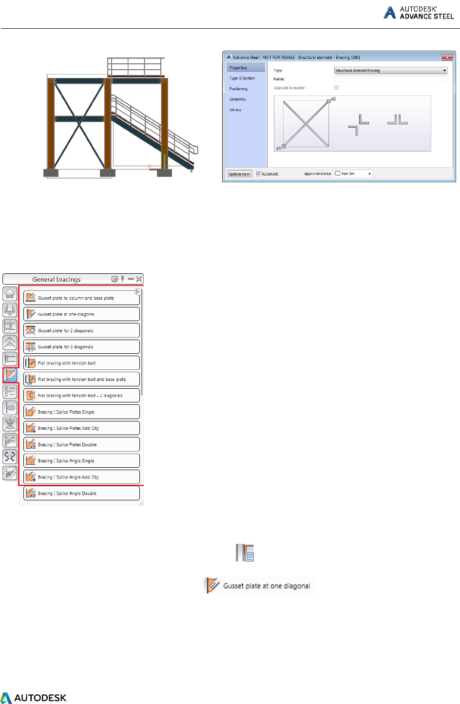
Creating a bracing
You can create a bracing, using the Bracing command on the ribbon.
To access the Bracing command:
1. Go to the Extended Modeling tab > Structural Elements panel and click (Bracing).
Note: Bracing creation is UCS dependent so make sure you set your UCS accordingly. Use the Move
UCS tool, from the Advance Steel Tools Palette > UCS category and set the UCS accordingly, to create the
view in the XY plane.
To set the UCS on the correct plane, use the UCS tools in the Advance Steel Tool Palette, UCS category:
2. Create your bracing in the XY plane by selecting two diagonal points on the two columns.
3. The bracing is placed and the properties dialog box appears, where you can make any required
modifications to your bracing.
ADVANCE STEEL Starting Guide
26
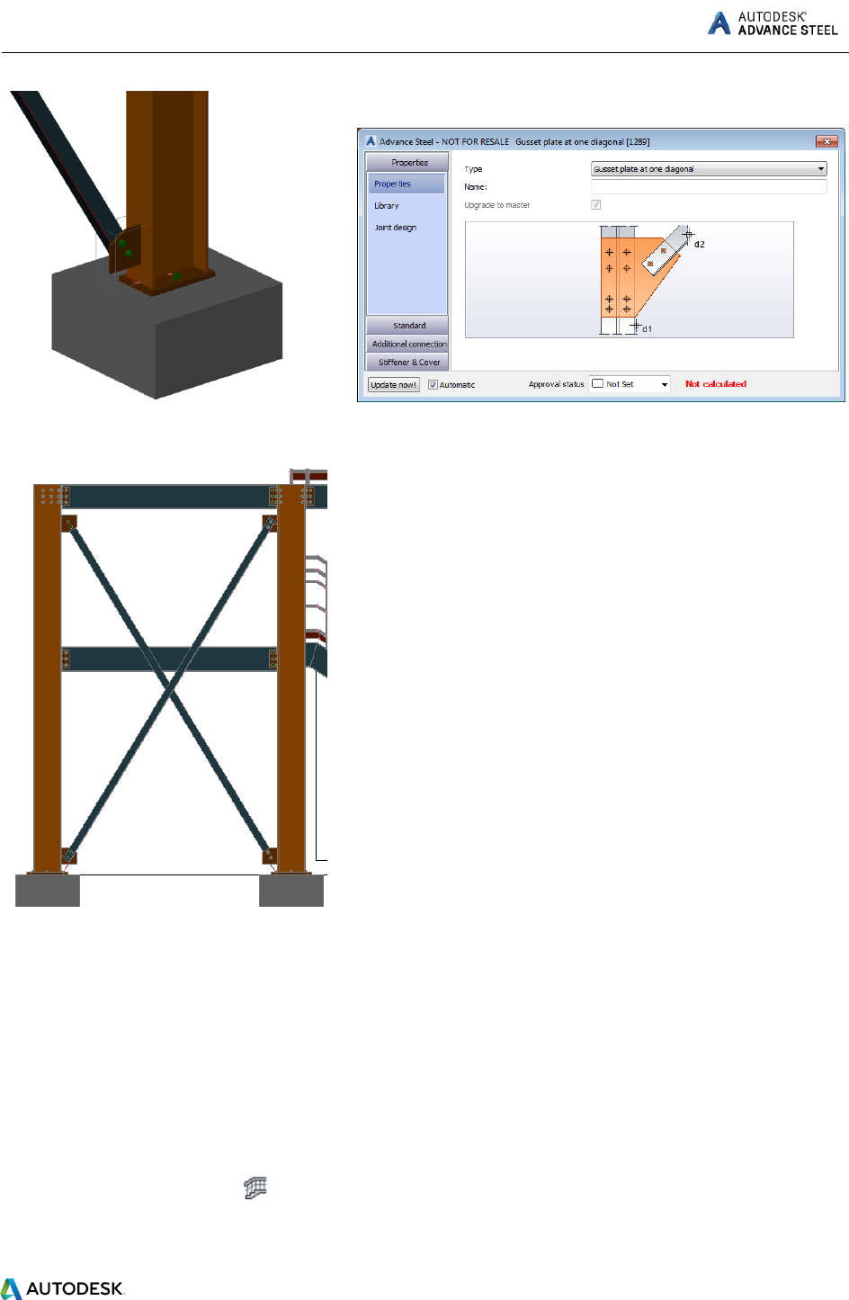
Now you’re ready to connect the bracing to the columns.
In this example, gusset plates at one diagonal will be created. The tools for connecting bracing members
using gusset plates are grouped in the General bracing category of the Connection Vault.
Example: Creating a Gusset plate at one diagonal connection.
1. On the Home tab, Extended Modeling panel, click .
2. From the General bracings category, select .
3. Select the column to connect and right-click.
4. Select the bracing beam to connect and right-click.
The connection is created and can be modified in the dialog box.
ADVANCE STEEL Starting Guide
27
Repeat the steps for the other 3 connections.
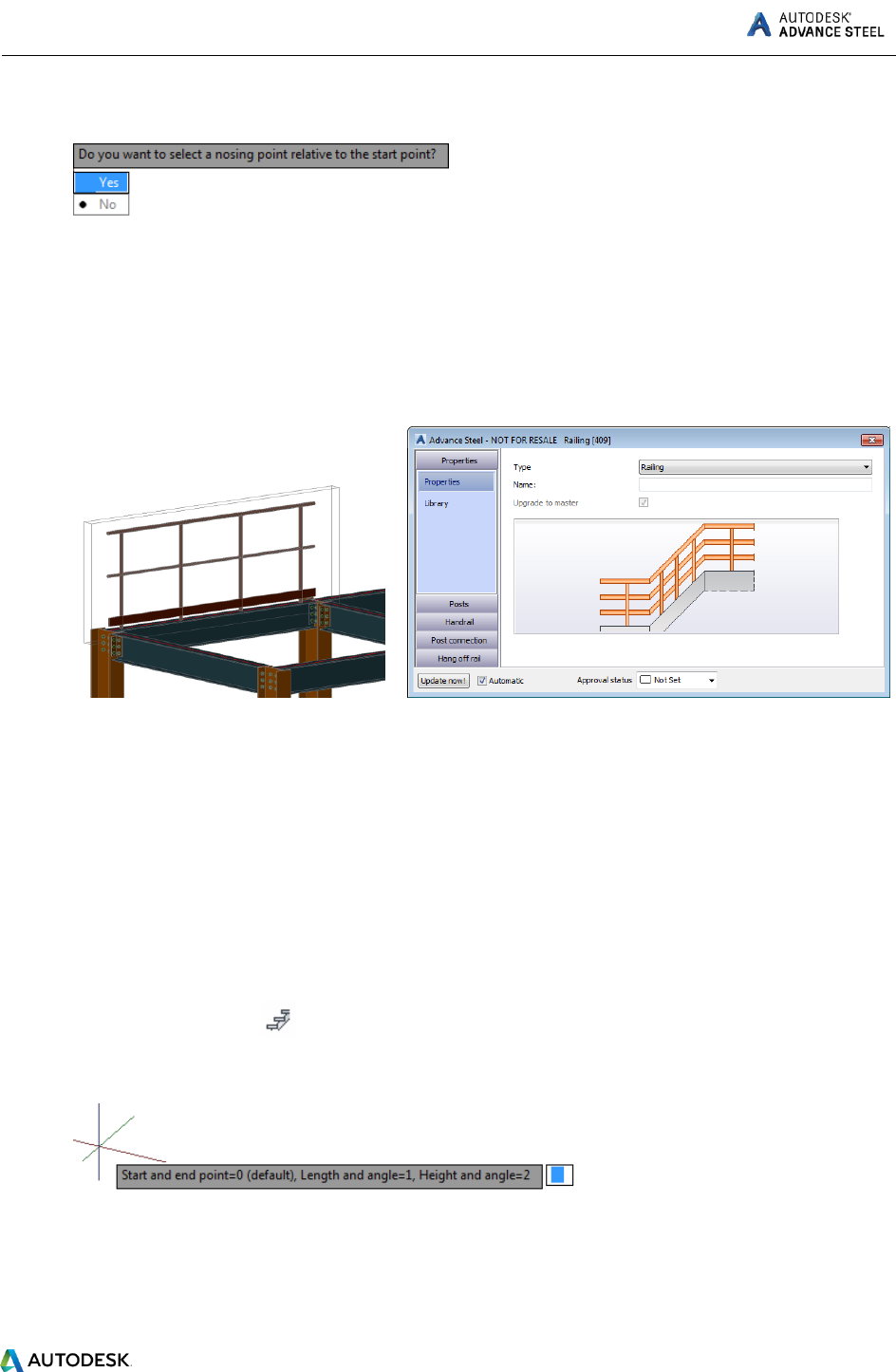
Inserting a hand-railing
The Hand-railing command on the ribbon easily creates a hand-railing along a beam, between selected
points. Simply select the beam and the points between which you want the railing to run and the hand-
railing is automatically created.
Example: Creating a hand-railing on a selected beam.
1. On the Home tab, Extended Modeling panel or on the Extended Modeling tab, Structural
Elements panel, click (Hand-railing).
2. Select the beam and right click.
3. Select a start point and an endpoint for the railing and right click.
ADVANCE STEEL Starting Guide
28
A message will appear, asking you if you want to select a nosing point relative to the start point.
4. Select Yes or No:
If you select No, the railing is automatically created and the properties dialog appears.
If you select Yes, after you select the nosing point, the railing is automatically created and
the properties dialog appears.
5. Make the necessary settings in the dialog box.
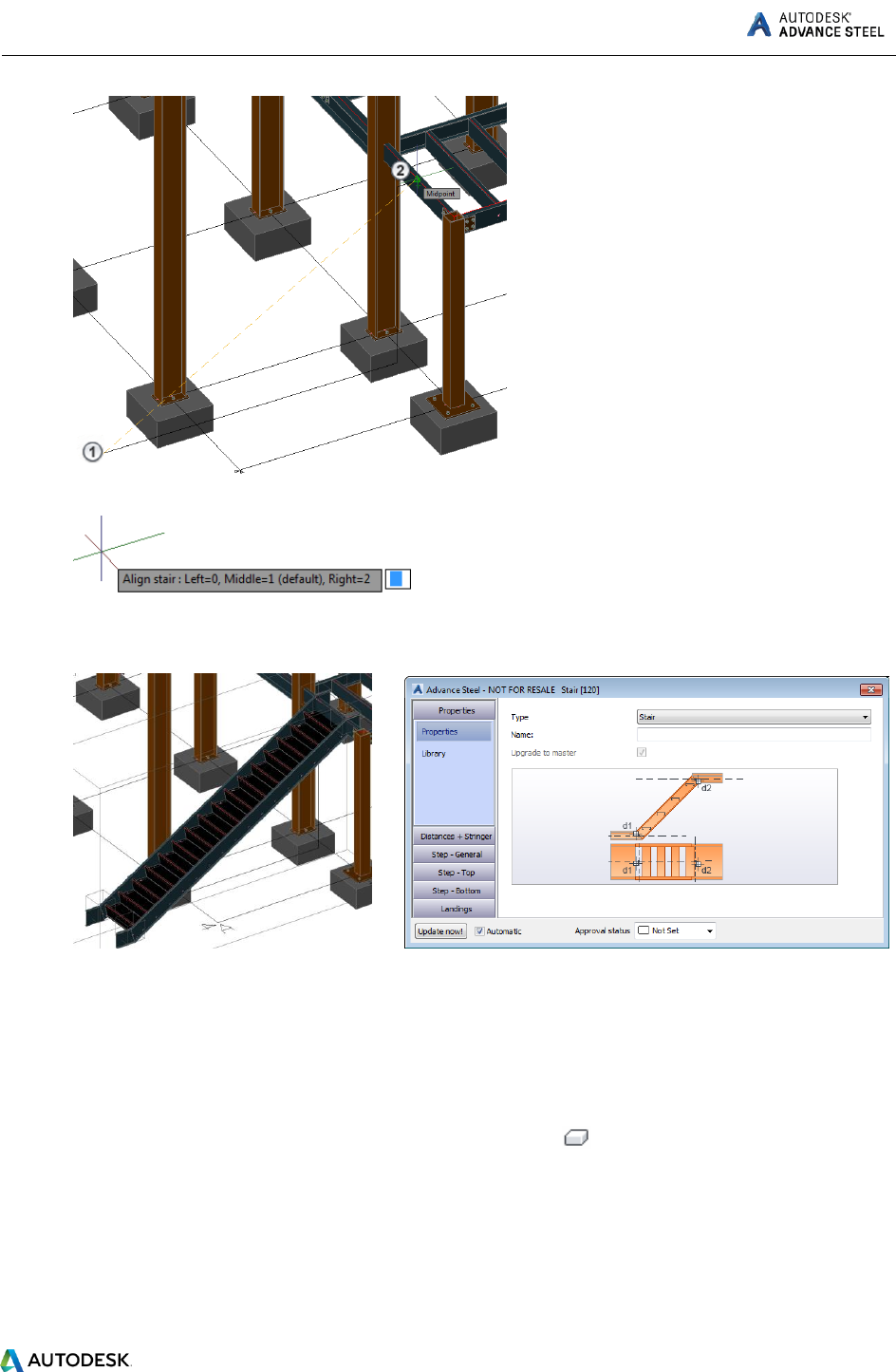
Inserting Straight stairs
You can easily create stairs; by using the stair creation commands (straight, spiral stairs or cage ladders)
on the ribbon.
Example: Creating a straight stair between two points.
1. On the Home tab, Extended Modeling panel or on the Extended Modeling tab, Structural
Elements panel, click (Straight stair).
2. You will have three methods to define the stair size: Start and end point, Length and angle or
Height and angle. Choose the default Start and end point method by pressing Enter.
3. Select the start and end point of the stairs.
ADVANCE STEEL Starting Guide
29
4. Choose the stair alignment (left, middle, right).
5. The stair is created and properties dialog box appears, where you can make the necessary
settings.
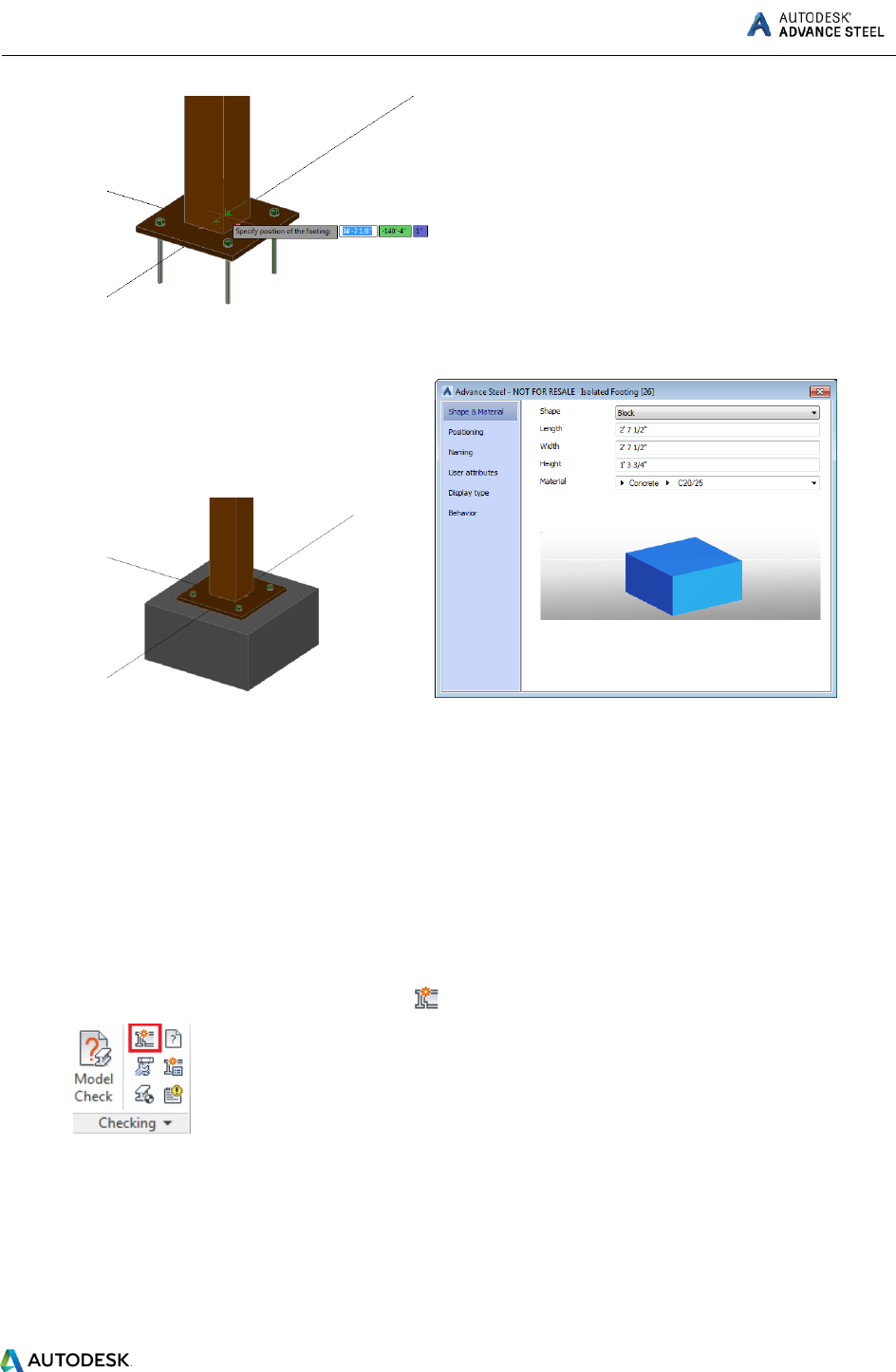
Inserting isolated footing
Example: Creating an isolated footing under a column base plate.
To insert an isolated footing:
1. Go to the Objects tab > Other objects panel and click (Isolated footing).
2. Specify the position of the footing or select a snap point to define its position under the
base plate.
ADVANCE STEEL Starting Guide
30
3. The isolated footing is created and the properties dialog box appears, where you can make
the necessary settings.
Clash check
A clash check tests if there are model interferences. Object interferences might be due to various
modifications made to plates, bolts, members and their connections. This tool finds all interference
cases so that they are fixed in the model before drawing creation.
The Advance Clash Check function checks selected elements or the entire model. Interferences are
displayed as red collision solids and listed in a text window.
Example: Checking the created frame for interferences
1. On the Home tab, Checking panel, click (Clash check).
The Clash check dialog box appears containing the list of all collisions. If there are no collisions, the
notification line displays “Collision check found no errors.”
2. Close the window.
ADVANCE STEEL Starting Guide
31
NUMBERING
The Advance numbering tool automatically numbers Single Parts and Assemblies for the entire model.
The numbering finds identical parts that should have the same number.
The numbering procedure is a single button function and works on the entire model or on selected
elements.
With automatic numbering all beams and plates obtain a single part mark. All other elements are
classified as attached parts. The numbering for single parts and assembly parts is done in one step or
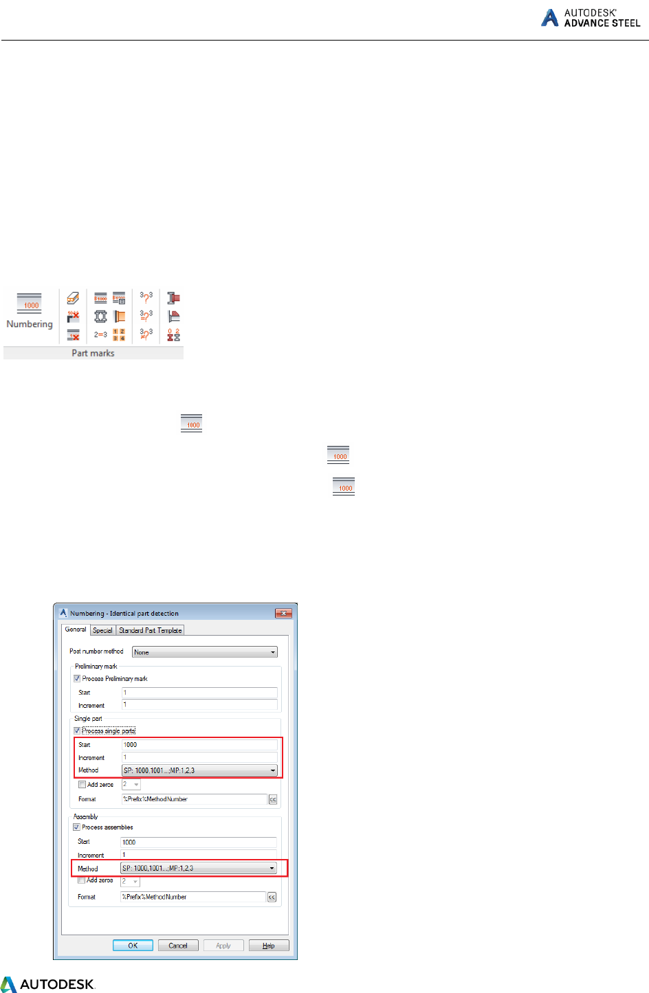
separately. The numbering tools are grouped on the Part marks panel of the Output tab.
Example: Numbering single parts and assemblies in one step.
1. On the ribbon, click (Numbering).
Home tab > Documents panel, click .
Output tab > Part marks panel, click .
2. In the Numbering dialog select Process single parts and define the: Start value, Increment value,
and Method of numbering.
3. Select Process assemblies and define the Method of numbering.
ADVANCE STEEL Starting Guide
32
The initial numbering gives temporary part marks such as B#internal1001. The final part mark
assigns after the Assembly and Single part drawings are created for those elements.
DRAWING CREATION
The 2D drawings are obtained after the design and numbering of the 3D model.
Advance offers a variety of drawing styles for the creation of general arrangement drawings, sections,
and shop drawings in various designs.
A drawing style is a group of instructions used to create a detail drawing. It defines how the elements
are displayed, labeled and dimensioned.
Drawing styles automatically create drawings with a layout configured exactly to the user's
requirements. Drawing styles are used similarly to AutoCAD's dimension styles, line styles etc.
The styles contain various settings (displayed parts, view, dimension, labeling, representation, etc.) in
database tables (libraries). Styles are available in the Drawing Styles Manager > Output tab
> Document Manager panel.
The preferred selection of the existing drawing styles, are displayed in the Drawing Style Palette.
The rules included in a drawing style can be modified. You can also define your own drawing styles.
A drawing style for a model or selected objects can be assigned during drawing creations. You can assign
it to an object when it is created or later via the Drawing Style tab in the Properties dialog. The drawing
style distinguishes between single parts and assemblies and it is used for drawing creation.
ADVANCE STEEL Starting Guide
33
The tools for creating drawings are grouped in Quick documents Palettes
There are three Quick Documents palettes:
1. Drawing Styles palette
2. Drawing Processes palette
3. BOM Templates palette
The palettes allow you to quickly browse and use drawing styles and drawing processes for drawing
creations as well as list templates for BOM list creations. The categories are represented by intuitive
images.
Drawing Styles palette
ADVANCE STEEL Starting Guide
34
Drawing Processes palette
BOM Templates palette
ADVANCE STEEL Starting Guide
35
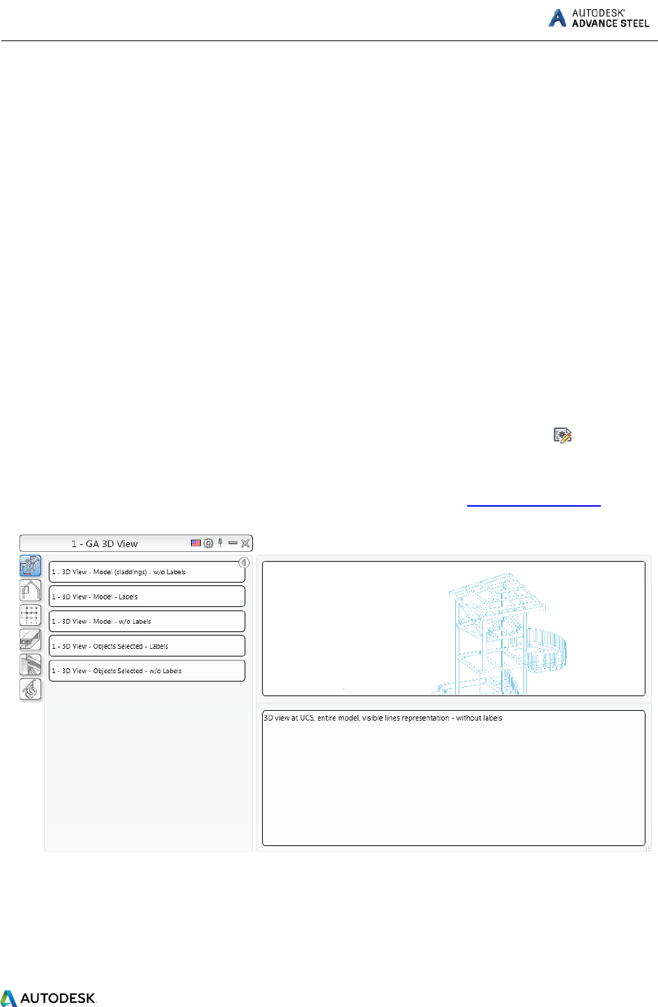
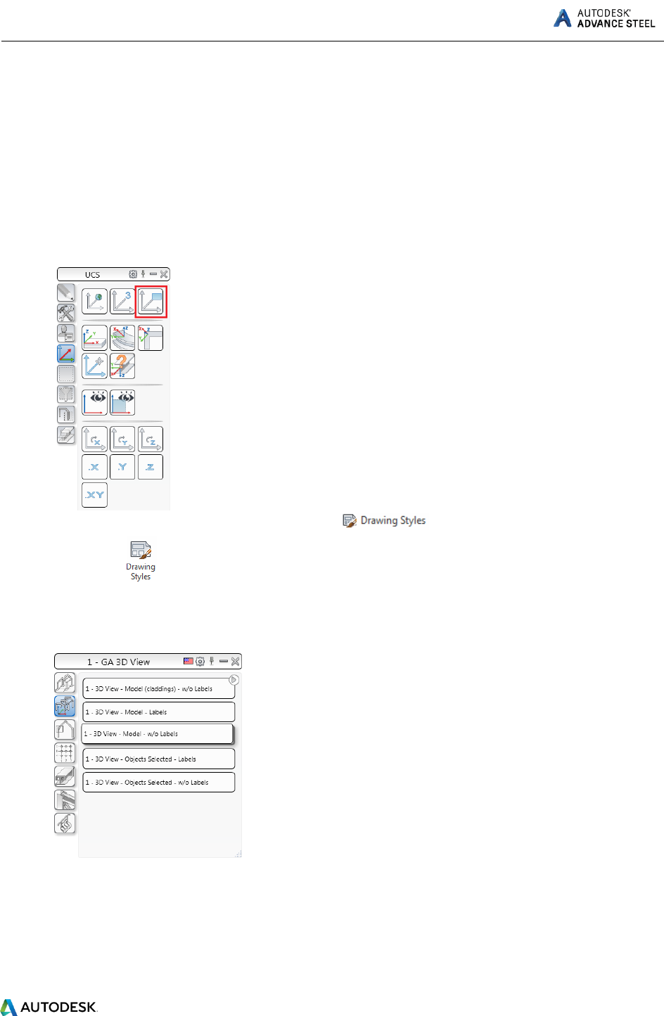
Example: Creating an isometric view.
Save the model prior to starting the drawing creation.
The viewport of the created view depends on the active user coordinate system (UCS). The view
direction is against the Z-direction of the UCS.
1. To create an isometric view, click on the UCS tool palette and place the UCS in the plane of the
screen.
2. On the Home tab, Documents panel, click or on the Output tab, Documents
panel, click .
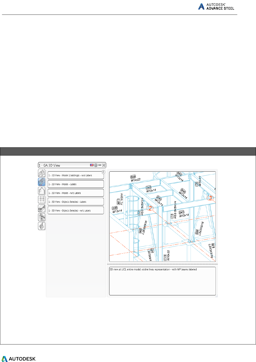
3. The Drawing Styles tool palette appears. In the 1 – GA 3D View category, choose one view type
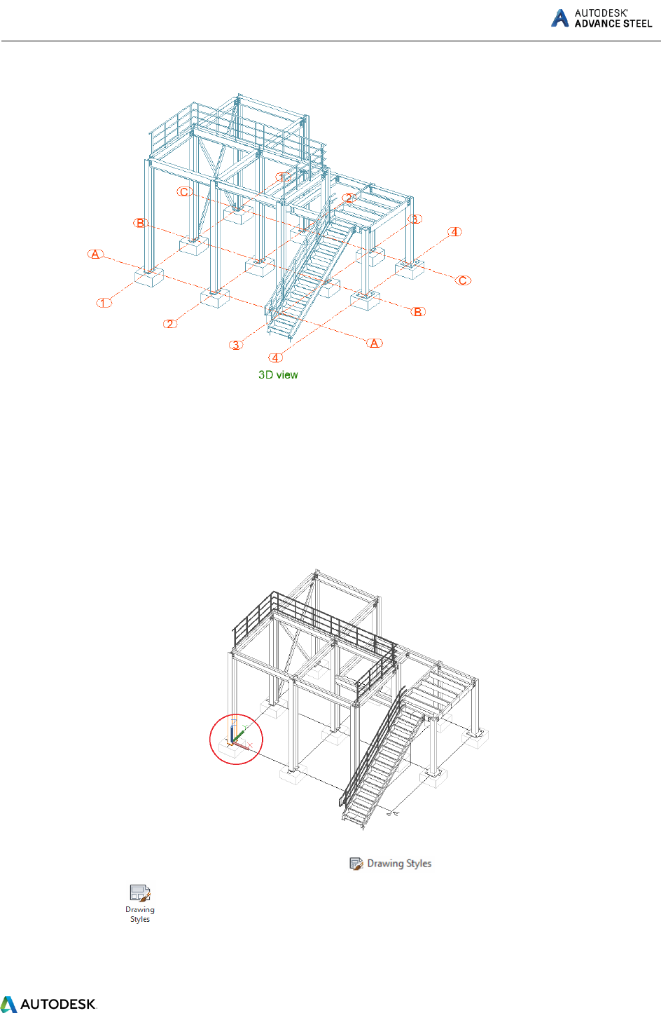
(e.g. 1 – GA 3D View – Model – w/o Labels).
4. The Drawing type dialog box appears.
5. Change the scale to 1/4”=1’-0”.

ADVANCE STEEL Starting Guide
36
6. Click OK to close the dialog box.
The Select destination file dialog box appears.
Set a path for a separate DWG in which the detail is placed.
Select the prototype template.
7. Click OK.
The drawing is created and saved as .dwg in the specified path.
ADVANCE STEEL Starting Guide
37
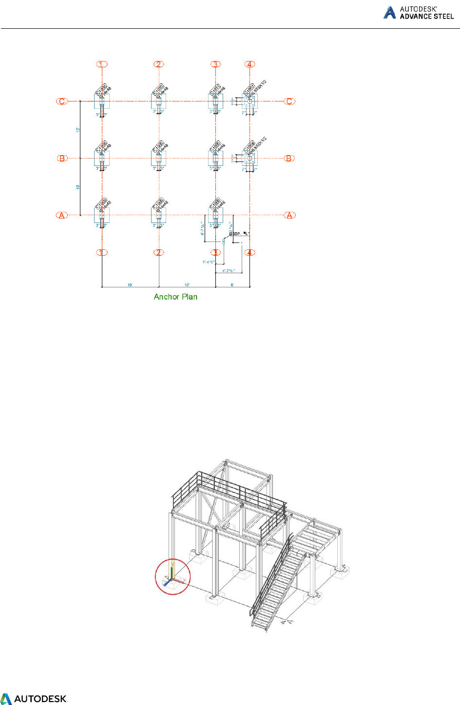
Example: Creating an Anchor plan view.
Save the model prior to starting the drawing creation.
The viewport of the created view depends on the active user coordinate system (UCS).
1. The view will be created in the XY plane. Set the UCS to correspond to the view direction, like in
the image below:
2. Go to the Home tab, Documents panel, click or on the Output tab, Documents
panel, click .
3. The Drawing Styles tool palette appears. In the 3 – GA Plans, Elevations / Sections category,
choose one view type (e.g. 3 – Anchor Plan – grid & holes dimensioned).
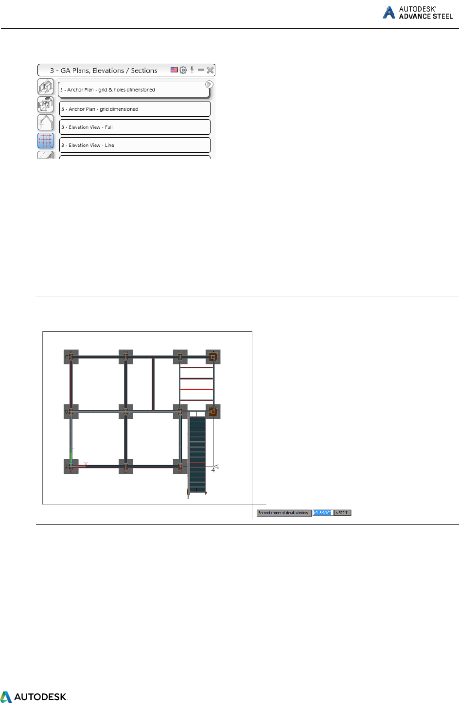
ADVANCE STEEL Starting Guide
38
4. The Drawing type dialog box appears.
5. Change the scale to 1/4”=1’-0”.
6. Click OK to close the dialog box.
The Select destination file dialog box appears.
Set a path for a separate DWG in which the detail is placed.
Select the prototype template.
7. Select two diagonal points to define the area of your view.
Note: For a more accurate orientation, select a Top view of the model.
8. Click OK.
The drawing is created and saved as .dwg in the specified path.
ADVANCE STEEL Starting Guide
39
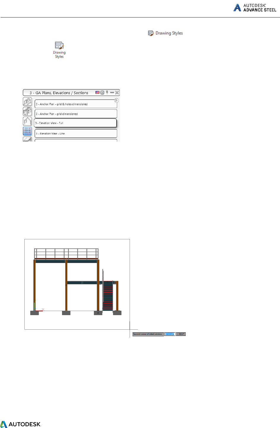
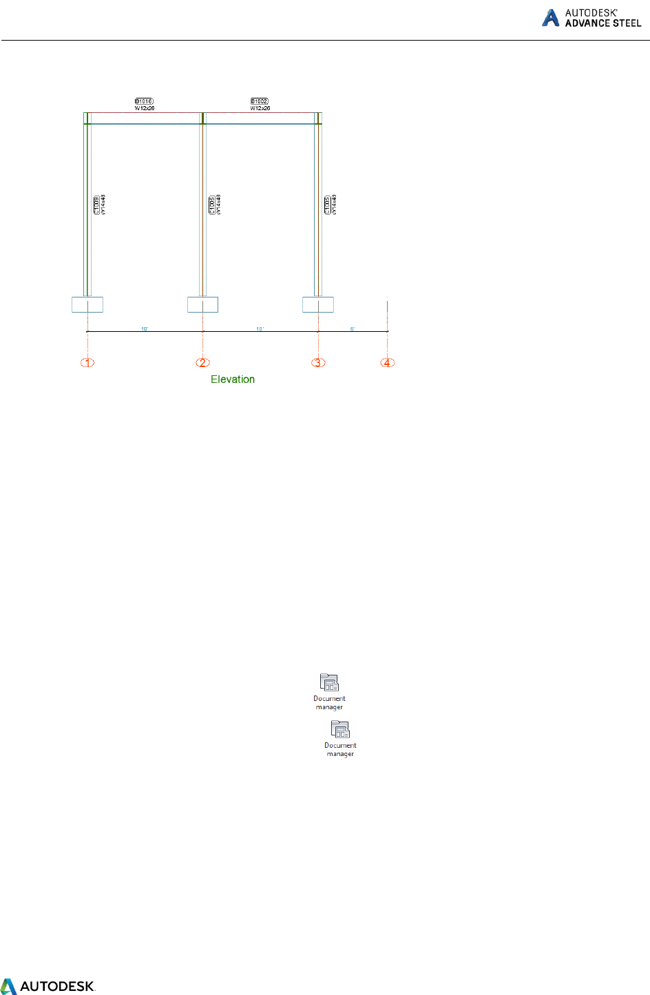
Example: Creating an Elevation view.
Save the model prior to starting the drawing creation.
The viewport of the created view depends on the active user coordinate system (UCS).
1. The view will be created in the XY plane. Set the UCS to correspond to the view direction, like in
the image below:
ADVANCE STEEL Starting Guide
40
2. Go to the Home tab, Documents panel, click or on the Output tab, Documents
panel, click .
3. The Drawing Styles tool palette appears. In the 3 – GA Plans, Elevations / Sections category,
choose one elevation view type (e.g. 3 – Elevation View – Full).
4. The Drawing type dialog box appears.
5. Change the scale to 1/4”=1’-0”.
6. Click OK to close the dialog box.
The Select destination file dialog box appears.
Set a path for a separate DWG in which the detail is placed.
Select the prototype template.
7. Select two diagonal points to define the area of your view.
8. Click OK.
The drawing is created and saved as .dwg in the specified path.
ADVANCE STEEL Starting Guide
41
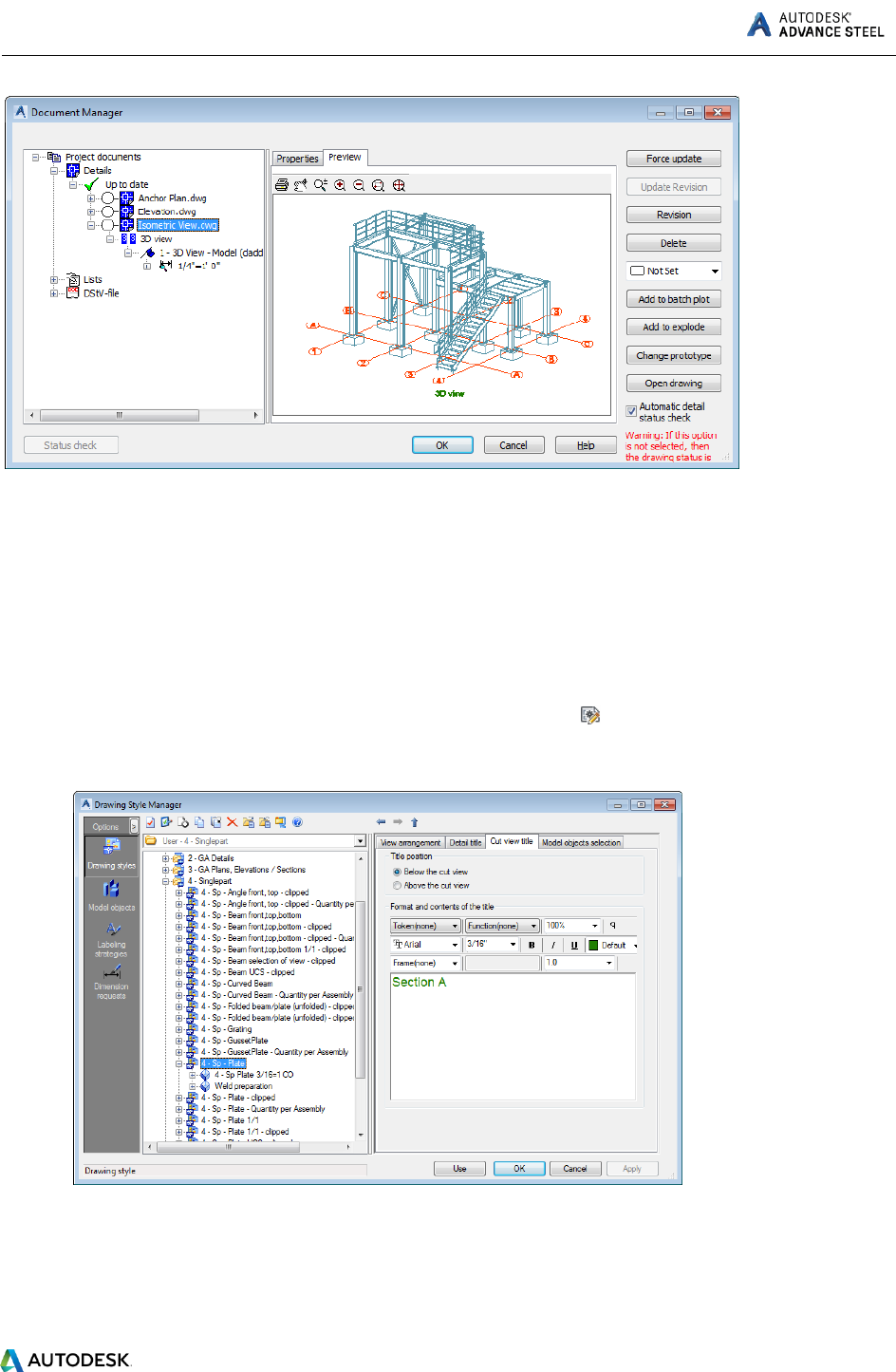
Drawing management
The Document Manager is used to preview, manage and erase the created details in separate drawings
(DWGs).
The link between the model and the drawing is managed automatically. Advance automatically detects
the details that require updating due to model modifications. The Document Manager also controls
drawing updates.
The Document Manager controls all dependent details and lists all information (e.g., which model
drawings have been created and how many). More than one detail can be stored in a single DWG. The
Document Manager tree structure shows the details that are in each DWG.
Opening the Document Manager
On the Home tab, Documents panel, click .
On the Output tab, Documents panel, click .
ADVANCE STEEL Starting Guide
42
z
The Document Manager lists all the created drawings, bill of materials / structured BOMs and the NC-
data created from the model. The documents are displayed on the Preview tab.
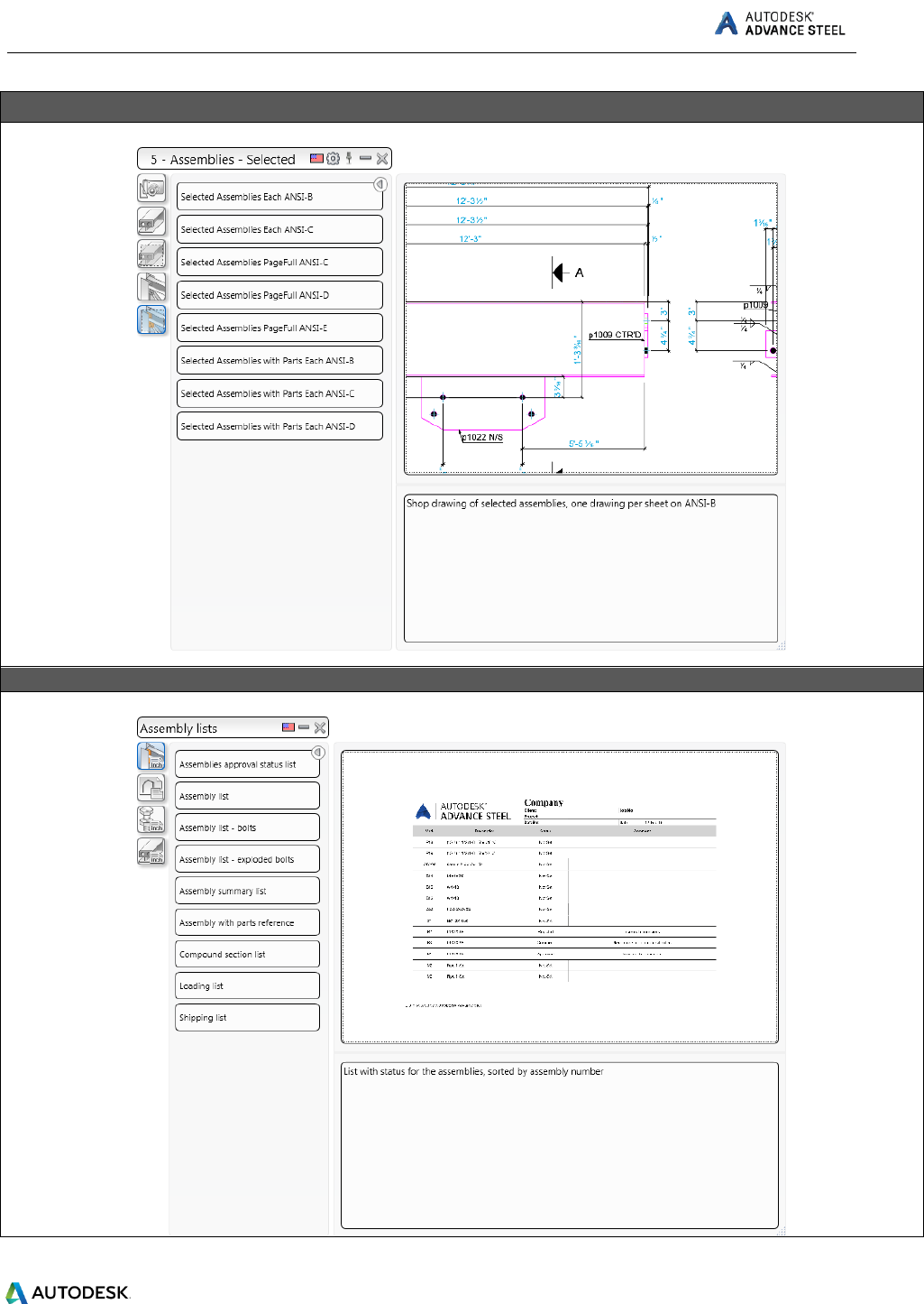
Create Shop Drawings
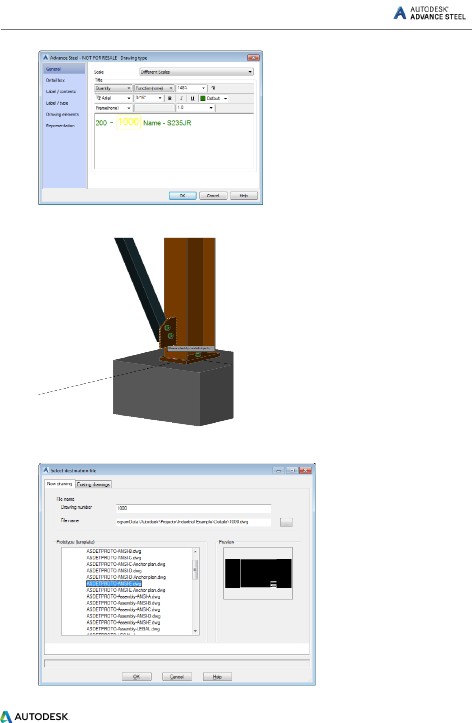
Example: Creating a single part plate drawing using a drawing style.
To create a single part detail drawing:
1. Go to the Output tab > Document Manager panel and click (Drawing style manager).
2. In the Drawing Style Manager window, select the desired drawing style, in this case Sp-Plate.
3. Click Use.
4. Make the desired settings in the next dialog and click OK.
ADVANCE STEEL Starting Guide
43
5. Identify and select the model objects you need to detail and right-click.
6. In the next dialog, choose a destination for your detail drawing and a prototype and click OK.

ADVANCE STEEL Starting Guide
44
7. In the next dialog, click OK.
8. Your detail drawing is created and saved as a .dwg file in the specified location. You can either
open it from the specified location or right-click on the model object and select Show part detail.
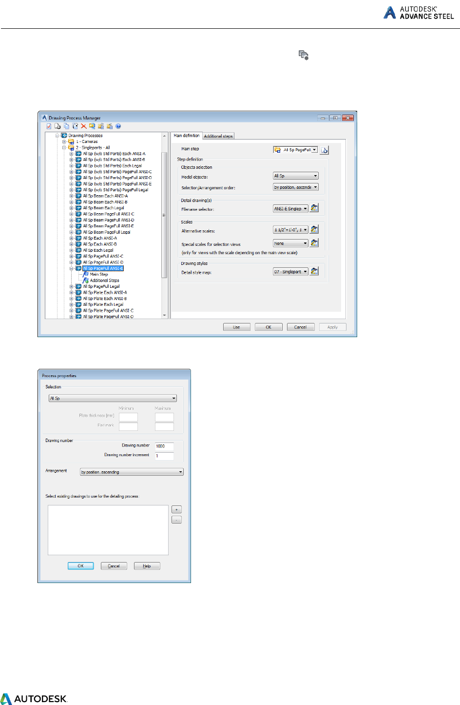
Example: Create a shop drawing with plates, using a drawing process.
To do this:
ADVANCE STEEL Starting Guide
45
1. Go to the Output tab > Document Manager panel and click (Drawing process manager).
2. In the Drawing Process Manager window, select the desired drawing process, in this case All Sp
Plate PageFull ANSI-E.
3. Click Use.
4. In the next window, click OK.
5. Your detail drawing is created and saved as a .dwg file in the Details folder; in the same location
your model is saved. You can either open it from that location or you can right-click on any of
the detailed model objects (in this case, on any plate) and select Show part detail.

ADVANCE STEEL Starting Guide
46
Note: If an object is detailed on more than one drawing, you will have more options to choose from in
the Show part detail contextual menu:

ADVANCE STEEL Starting Guide
47
LIST CREATION
To quickly create a Bill of Material list you need to access the preferred BOM templates, using the Quick
Documents - Bill of Material template.
1. You can open the Quick Documents BOM template palette:
Home tab > Documents panel >
Output tab > Documents panel >
2. To create a list, click on any of the available templates.
Note: You can also preselect objects in the model, and the BoM template list will be created only for the
objects in the selection.

ADVANCE STEEL Starting Guide
48
Once the list is created, it will be opened in the BOM Viewer and can be saved and registered to the
model.
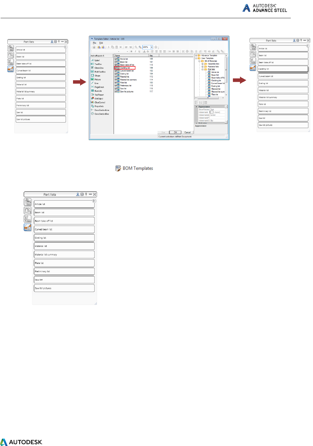
To add or remove BOM templates from the User category of BOM templates - Quick Documents palette,
you need to set the status of the checkbox associated to the BOM template list in the BOM Editor.
Note: Change palette content category - Advance / User / Country: You can switch between categories
by clicking the first icon on the palette title bar - the content of the palette will change depending on the
chosen category:
The icons differ for each category:
ADVANCE STEEL Starting Guide
49
Example: Create a Material List.
1. Home tab > Documents panel >
2. The BOM Templates palette appears.
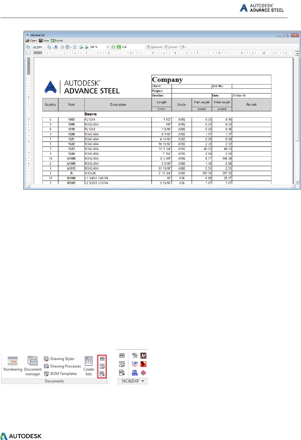
3. From the Part List category, select Material List.
The Material List appears. It can be printed, saved, exported to PDF (and other formats) or sent
by e-mail using the corresponding icons on the menu bar.
ADVANCE STEEL Starting Guide
50
4. Click Export. The Report export dialog appears displaying the export options.
5. Select an export format from the list.
6. Click OK.
7. Save the created BOM file. A file name is requested in a new window. The BOM file is saved as a
Report in the ...\[model folder]\[model name]\BOM\[BOMfilename] folder.
CNC DATA CREATION
Advance Steel produces CNC files (DSTV format) for workshop machinery directly from the 3D model.
You can either select one model object or the entire model to create these types of files.
You can access the commands for the CNC data creation from:
The Output tab > NC&DXF panel
The Home tab > Documents panel
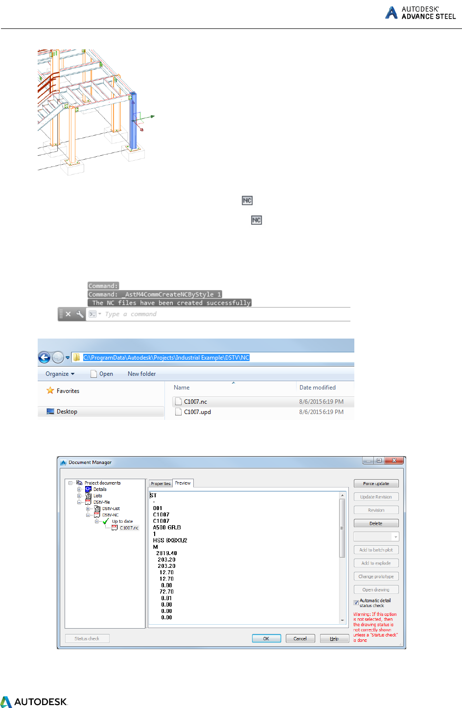
Example: Create an NC file for a selected model object.
1. Select a model object.
ADVANCE STEEL Starting Guide
51
2. Go to:
The Output tab > NC&DXF panel and click
The Home tab > Documents panel and click
3. The NC file is created and is saved in the DSTV folder that is automatically created in the same
location as you model DWG.
You can also access the NC files, using the Document Manager, where you can see a preview of the file.

ADVANCE STEEL Starting Guide
52
This small exercise was a very simple introduction to Advance Steel. In time, your familiarity, speed, and
understanding of the power and versatility of Advance Steel will improve, as you use the software on
real projects.
RECOMMENDED PRACTICES
Saving the project
1. Create a folder structure to store your projects in correctly, create a projects folder and then
create sub folders for each project.
In that folder store the model which then creates its own relative folder and required sub
folders. This keeps all models and databases separate and avoids conflicts.
2. Create an AutoSave folder location and adjust your system to save your automatic backup files
to that known location, keep it simple and at the root of the System such as
C:\AdvanceSteel\Autosave.
3. Save your model at regular intervals.
4. Use a suitable Name for the Model such as the contract number, project reference or place
name. This can be useful later on in the project, as the model name can be listed in the drawing
and NC naming and also be linked to the actual file references.
Modeling
5. Always start your model at 0, 0, 0 in the World Coordinates.
6. Be aware of how you model a beam/section “Right to left” or “left to right”, as this can influence
how the front and the back of beam are displayed on an assembly drawing.
7. Columns – Always try to model so the Z Axis of the column flange is to the outside face of the
building for perimeter columns.
8. System-line placement – When modeling horizontal members, roof members, floor beams, etc.
always try to have the system line in the top of the profile at the middle of the flange. This
affects the assembly drawing dimensioning.
For Columns try to keep it in the center, unless you have a specific need for one column flange
face to be at a set location, as this means that if you change section then the change in size goes
away from that face. So the flanges still remain in line. This is sometimes used where cladding is
applied directly to hot rolled steel flanges.
For purlins and Rails, try to keep the system line to the bottom face nearest the supporting
beam, as then if the size changes for the rail, the difference goes outwards, rather than altering
the hot rolled frame set-out.
Always try to make sure your system lines meet for beams columns etc. This is like you wire-line
in the model and with this it is easy to check the primary position of and object, also the system
line is used as the datum for the dimensioning of the Drawings and in other aspects of the
modeling.
9. Remember your UCS; this is a vital tool in placement and orientation of objects within the
Advance Steel environment.

ADVANCE STEEL Starting Guide
53
10. For complex setting out of a building, say radial etc., always try to have some
reference/construction line geometry in the system, create a layer and place it in there, it can be
turned off, but is always there for reference.
11. Before you model a beam type, like poly-beam, or curved beam, consider how you are going to
manufacture it and more importantly how you are going to detail it.
For simple curves use curved beams, rather than poly beams
For complex beams, that may appear too easy to create as poly beams, look at how the
original shape line is created. Is it from a series of curves of known radii, if so, model it
as a series of curved beams as you will buy it as curves and then weld or joint together.
Poly-beams do not lend themselves to being dimensioned as radii; they work on points
based upon the references they were created from.
KEEP IT SIMPLE – SIMPLE TO MODEL = SIMPLE TO MAKE.
12. Note the difference between holes and contours, make a decision on how the hole will be
produced, drilled or cut out via cutting torch or profiler. This affects drawings and NC
processing. For drilled holes use the Hole commands. For profiled holes use the Contour
commands. The size of the hole makes no difference to how the NC describes it.
13. Assess your project before you start, look at how you are going to build the structure, how it is
going to be delivered, where you are starting from, craneage etc. You can model it in Advance,
but you are the one driving it, it goes where you steer it.
14. Try to use Macros where possible for Joints. When using macros, if you create a joint and think
you may use it again somewhere, store it in the table with a suitable reference. For example
bracings, you can set one up for Flats and one for Tubes, save each to the table and then when
inputting bracing you can just select that default.
15. Use project Explorer to manage the model structure, set up views so it’s easier to work on plan
or elevation at a time.
16. Always use model roles, as this defines the prefix in numbering and also has influence with the
drawing output. The drawing styles link to the Model roles to set the style within the process.
Numbering
17. Use the standard numbering rules set in Advance Steel and try to work with those, always let
program update the model numbering, DO NOT MANUALLY NUMBER UNLESS YOU HAVE TO,
this can lead to problems.
18. If model is not complete, then try numbering using the Lot/Phase option with the box ticked.
This means that the existing part of the model will have unique numbers. These numbers will
not be used elsewhere in the model in later phases. This means you can carry on modeling and
then just renumber at a later stage and numbers / items from phase 1 will not alter their
numbers.
19. Use the preliminary numbering of the model; adjust the BOM lists to include preliminary
numbers. These references never change and can be a good way to track items whose final

ADVANCE STEEL Starting Guide
54
number has changed. For example if pre ordering curved beams this reference can be used to
track that component.
Creating drawings
20. GA Drawings
Think about what you want before you start; map out how you are going to approach the
drawings. For example floor plans first in level order, from ground up, then Elevations going
around the building, Sections through the building, local details of special joints / typical joints,
3D Views of model. Lot phasing 3D views.
Plan it on a piece of paper, make a list, assign the drawing numbers for GAs to follow this
pattern, so you may have 5 drawing for plans, 4 for sections, etc.
Think about the SCALE on the paper, can you combine two elevations onto one drawing etc.
21. Parts Drawings
Think about how they are going to be manufactured – in house, sub contracted off profilers etc.,
all ordered in at once or in phases. This may change the paper size you choose to produce the
drawing on. A3 or A4 single item, puts each part on its own drawing, makes it easy to send, each
drawing is relative to each part and that part only.
22. Assembly drawings
Think about how they are going to be fabricated – all in one shop, subcontracted to various
workshops, in phases etc. Sometimes easier to do single drawings for each assembly, as can be
fitted onto smaller A3 size, most small fabricators only have limited printing facilities, so sending
A1 drawings can mean that they print of at vastly reduced size leading to mistakes, omissions or
lots of phone calls to clarify what something is. So set up to smaller sheet to start with a larger
scale to show the details clearer.
23. Check the drawings – sometimes things get missed or mixed up in the model, and are not always
picked up. Use the drawings to check what is being produced. A quick review can save you time
and money in the long run.
Lists
24. Filter the model to produce lists for required items; use the lists that are set for Curved Beams,
plates, beams. Use the list to check the model and that you have done all the drawings and
things don’t get missed.
NC files
25. If you want only plates of a certain size then use search filter to find and select them, then
create the NC files. You can adjust the naming of the files and details shown on the hard stamp
to include things like thickness, number off etc., using the defaults.

ADVANCE STEEL Starting Guide
55
26. Be aware of the Defaults in the Management Tools; there are many settings it there that can be
adjusted to change the out-come of drawings and modeling etc., depending upon what you
require.
27. When building onto an existing structure this can be modeled in Advance, but you must
remember to set that structure so that it is not used for the Drawings or BOM. These settings
are on the Behavior tab in the object properties dialog. What this does is set it so that when the
model is numbered, these existing components are numbered but with a negative value and are
not consider for drawings or material lists.
