Autodesk Impression 2 Feature Overview X Tipstricks
2016-06-08
: Guides Tipstricks Autodeskimpressionoverview tipstricks_AutodeskImpressionOverview tips pdf asi
Open the PDF directly: View PDF ![]() .
.
Page Count: 19
www.au
t
A
UTO
Fe
Quic
grap
fast
a
colle
lines
DW
F
own
look.
sav
e
grap
your
that
y
and
b
sim
p
t
odesk.com/im
DESK
®
IM
P
atur
e
kly crea
t
hics wit
h
a
nd eas
y
agues a
to wate
r
F
™
files
u
custom
A
nd be
c
e
styles,
y
hics wh
e
signatu
r
y
our offi
c
b
uilt-in l
e
p
le to lea
pression
P
RESSIO
N
e
Ov
e
t
e comp
e
h
Autode
y
way to
nd clien
t
r
color w
a
u
sing pr
e
styles t
o
c
ause I
m
y
ou can
e
n desig
n
r
e style
(
c
e prod
u
e
arning
r
rn.
N
2
e
rvie
w
e
lling, p
r
sk
®
Imp
r
make a
n
t
s. Add
e
a
shes t
o
e
built sty
l
o
convey
m
pressio
quickly
u
n
s chan
g
(
or style
s
u
ces. Be
s
r
esourc
e
w
r
esentati
r
ession
s
n
impac
t
e
verythi
n
o
your D
W
l
es, or c
r
your o
w
n enabl
e
u
pdate
p
g
e, as w
s
) to all t
h
s
t of all,
e
s make
on-read
y
s
oftware
t
on
n
g from
p
W
G
™
an
d
r
eate yo
u
w
n uniqu
e
e
s you t
o
p
resenta
t
ell as a
p
h
e draw
i
familiar
Impress
y
, the
p
encil
d
u
r
e
o
t
ion
p
ply
i
ngs
tools
ion
AUTODESK IMPRESSION 2 FEATURE OVERVIEW
2
Contents
User Interface ................................................................................................................... 3
The Jump Start Tour ..................................................................................................... 3
The Canvas, the Toolbox, and the Dashboard ............................................................. 4
The Style Editor ........................................................................................................ 4
Navigating the Canvas ............................................................................................. 5
Bringing Files into Autodesk Impression ....................................................................... 5
Opening Files ........................................................................................................... 5
DWG Import Wizard ................................................................................................. 5
Import Files or Graphics ........................................................................................... 6
Working with Layers ................................................................................................. 7
Working with Appearance Styles .................................................................................... 8
Applying Appearance Styles ......................................................................................... 9
Layer Styling ............................................................................................................. 9
Area Fill Styling ...................................................................................................... 10
Auto Layer .............................................................................................................. 11
Area Fill Anchors .................................................................................................... 12
Match Properties .................................................................................................... 13
Stylizing Multiple Illustrations with Style Mapping ....................................................... 13
Blocks.............................................................................................................................. 14
Adding Entourage Elements ....................................................................................... 14
Block Editor ................................................................................................................ 15
Block Substitution ....................................................................................................... 15
Editing Styles .................................................................................................................. 16
Updating Your CAD Geometry ...................................................................................... 17
Performance Tuning ...................................................................................................... 17
Layer Packing ......................................................................................................... 17
Performance Tuner ................................................................................................ 18
Sharing Impression Images ........................................................................................... 18
More Resources ............................................................................................................. 19
Impression Community ............................................................................................... 19
Communication Center ............................................................................................... 19
AUTODESK IMPRESSION 2 FEATURE OVERVIEW
3
User Interface
The intuitive Autodesk® Impression software user interface helps you get up and running
quickly.
The Jump Start Tour
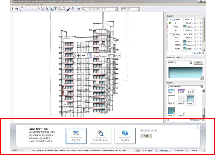
The first time you open Autodesk Impression software, you see the Jump Start Tour
interface at the bottom of your screen. The Jump Start Tour helps you understand the
basic concepts of creating a rendered image in Impression through easy-to-follow, step-
by-step exercises and informational videos.
Just follow five simple steps in each of the three sample files, and you are on your way to
making a rendered illustration.
Once you finish and close the Jump Start Tour, the main canvas is fully expanded. For a
more in-depth introduction to the application, see the Quick Start Guide, accessible from
the Help menu.
Figure 1. The Jump Start Tour
AUTODESK IMPRESSION 2 FEATURE OVERVIEW
4
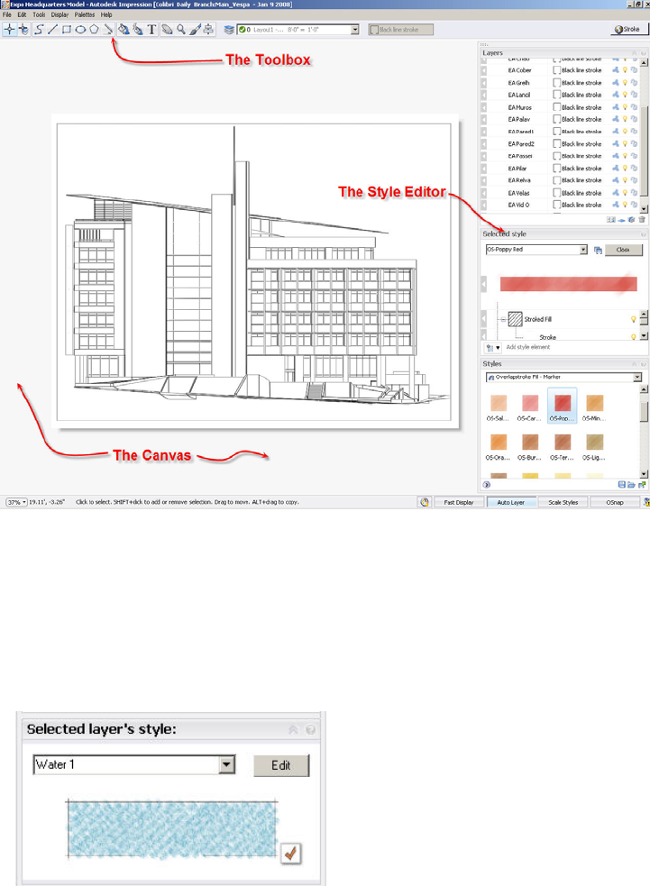
The Canvas, the Toolbox, and the Dashboard
The primary components of the Impression user interface are the canvas, the toolbox, and
the dashboard. The dashboard can be docked on the right or left side of the screen.
The canvas is the main drawing area where you stylize the image. This is where the
geometry and text from the files you open or import are displayed.
The toolbox contains tools for selection, geometry and text creation, stylization, and
navigation (such as Pan and Zoom).
The dashboard contains the most commonly used palettes, such as the Layers palette,
the Style Editor, and the Styles palette.
The Style Editor
While working in Impression, you will often refer to the Style Editor. This palette displays
context-sensitive information related to the styles of geometry, layer, or block that you are
modifying. When you edit or modify a style in the Style Editor, the Style Editor label
indicates what will be updated. In this example, the layer style will be updated.
Figure 3. The Style Editor; click Edit to
change elements of a style
Figure 2. The Impression user interface
AUTODESK IMPRESSION 2 FEATURE OVERVIEW
5
Navigating the Canvas
Panning and zooming in Impression is simple and intuitive, especially if you are
accustomed to Autodesk products.
You can pan and zoom in various ways, including pressing the P and Z keys to activate
the tools, clicking icons, and using right-click and pull-down menus. You can also roll the
mouse scroll wheel to zoom and press the spacebar and drag to pan.
To temporarily turn off all open palettes, just press the Tab key. Press it again to restore
your previous configuration.
Bringing Files into Autodesk Impression
When working in Impression, you can open or import DWG and DWF files, as well as IRF
files, the native file format for Impression. In Impression, each opened or imported view
becomes a separate sketch that contains its own set of layers.
Opening Files
When you open a DWG file, the DWG Import wizard enables you to choose specific
settings for the file before it is opened on the canvas.
For example, you can select a default stroke for all imported geometry. (You can also
specify a plot style table—or use a combination of assigned stroke and existing plot style.)
The stroke stylization you choose is apparent as soon as the image appears on the
canvas.
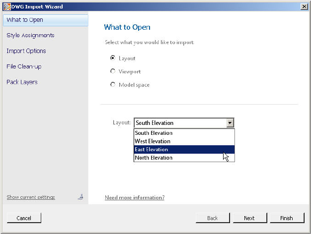
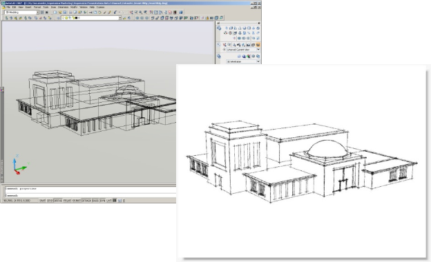
DWG Import Wizard
Whether you are creating a plan, an elevation, or a perspective view of a 3D model, the
options in the DWG Import wizard are the same.
By default, layout views (paper space views) retain their native page size and scale.
However, for model space views, the geometry is scaled to fit the default canvas size. You
can specify a new canvas size and orientation as you open the drawing in Impression.
Groups of DWG objects on the
same layer can be packed into
one object with the DWG Import
wizard. This capability provides a
performance gain that makes
editing complex drawings easier.
Packed layers can be unpacked
at any time.
Figure 4.
The DWG Import wizard
AUTODESK IMPRESSION 2 FEATURE OVERVIEW
6
Although Impression converts all drawings to 2D, you can open and render 3D drawings.
For example, to render a perspective view, first save a layout with the viewpoint you want,
perhaps a view through a camera. You don’t need to worry about hiding lines; Impression
does that for you. In the DWG Import wizard, in the Import Options panel, click the 3D
Import Options button to see other 3D import options.
Import Files or Graphics
You can import other CAD or graphics files into a blank canvas or an existing illustration.
A variety of file types can be imported into Impression, including IRF, DWF, DWG, BMP,
JPEG, GIF, PCX, PNG, PSD, TGA, and TIFF.
Raster images imported into Impression are placed on the current layer. When you import
a vector file, such as a DWF or DWG file, into an existing Impression drawing, the layers
from each view are organized within new sketches. The sketch and its imported layers
appear at the top of the Layers palette.
Note: Importing a file is different from opening a file. The Import operation is similar to
inserting an external file into a drawing in AutoCAD® software.
Figure 5. Creating a
perspective view in AutoCAD
AUTODESK IMPRESSION 2 FEATURE OVERVIEW
7
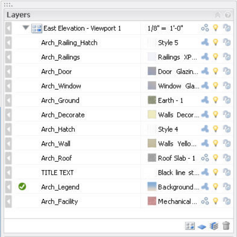
Working with Layers
The Impression Layers palette provides a powerful way to work with your design
illustrations. Each Impression layer has an assigned appearance style that affects how
geometry on that layer is stylized.
The Layers palette enables you to
Assign a style to all the objects on the layer.
Control the visibility of individual layers or layer groups by turning them on or off
or by setting their opacity.
Lock layers to keep them from being modified.
Set the drawing order of layers simply by dragging them up or down in the layer
list. For example, for an elevation, you can control which objects are in the
background or the foreground. Objects on layers that are on the top of the stack
appear in front of or on top of objects on other layers.
Pack or unpack objects on a layer.
Create layer groupings that can be treated as a set.
Manage sketches that are created from imported CAD files. (Sketches control the
scale of the layers and their objects.)
Create separate sketches in order to view the same set of layers with different styles, for
fast, iterative studies. (This is similar to the Current Viewport Layer functionality in
AutoCAD.)
Figure 6. The Layers palette, an
element of the dashboard
AUTODESK IMPRESSION 2 FEATURE OVERVIEW
8
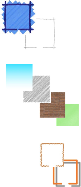
Working with Appearance Styles
Impression styles are graphic treatments that are applied to linework or used to fill areas
of your drawings. They are the fundamental method used to turn your CAD linework into
rendered illustrations.
A style is usually a composite of media, fills, and effects, but it can be as simple as a
pencil stroke or solid color.
Some style elements include the following:
Media
Marker
Pencil
Fills
Gradient
Stroked
Texture
Uniform
Effects
Fills and media can be modified
using effects:
Roughen
Drop shadow
Paper
Different types of paper also enable you to customize the look of a fill style:
Standard
Pastel
Coarse
Fine
AUTODESK IMPRESSION 2 FEATURE OVERVIEW
9
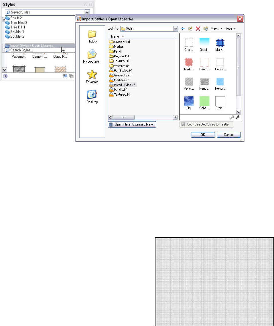
Libraries of prebuilt styles are included with Impression, ready to be directly applied to
your drawing. You can browse through different external libraries of styles and import the
entire library for use, or select and import individual styles from within an external library.
Of course you can always edit and change these prebuilt styles to create your own
custom styles. There are many ways to customize a set of styles that you can export as a
library to be reused in other illustrations.
Applying Appearance Styles
You can apply styles to a CAD drawing in Impression in several ways. Depending on the
source file and how the layers are organized, you may want to assign styles by layer, by
object, to a closed area, or by using a combination of techniques.
Layer Styling
By default, all linework comes into Impression with the stroke
style that you choose in the DWG Import wizard. The default is
the Black Line Stroke style, but you can choose a number of
other strokes, such as Gray Pencil or Dashed Line.
Using layer styling, you can quickly apply a style to all of the
objects on a layer in your drawing. For example, in a site plan,
you may want to have all of the paving represented by a uniform
style. By using layer styling you can quickly apply a uniform
paving style to all of the paving in your drawing that is on the
same layer.
Line Style Overrides
You can also apply styles to individual geometry
by dragging a style swatch directly from the
Styles palette onto an object. This becomes a
style override, since the style for that geometry
now differs from the other geometry on that
layer.
Note: If you change the style of a layer later,
the geometry with the override will not change
to the new style.
Figure 7. The Import Styles and
Open Libraries dialog box
AUTODESK IMPRESSION 2 FEATURE OVERVIEW
10
To apply an appearance style to the geometry on a specific layer, simply drag the
thumbnail swatch of the style from the Styles palette onto the desired layer row in the
Layers palette.
Area Fill Styling
Geometry is the basis for all CAD files, and hatch patterns are often used to fill enclosed
areas with colors and textures. Using styles that contain standard or composite fills, you
can stylize large or small areas of your drawing using a method called Area Fill, which is
similar to the way hatches are applied in AutoCAD software.
Note: Autodesk Impression reads the hatches in DWG files and imports them as styles in
Impression.
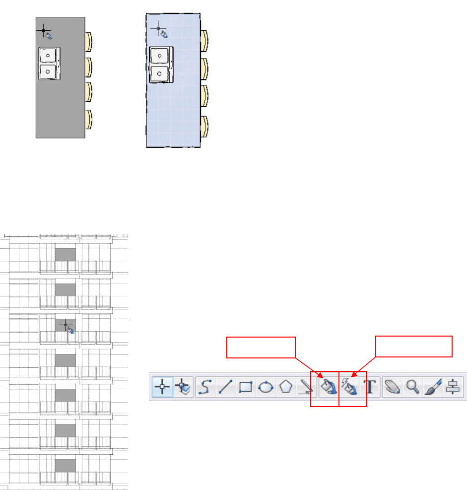
The Area Fill tool floods a closed area with the style that is assigned to the current layer.
A fill can be contained by any intersecting lines that enclose an area, even if they are
separate objects on different layers. When you insert an area fill, you create a separate
area fill object.
You can also fill areas by clicking a single point or by
drawing a line or window to indicate areas to be filled.
The Power Fill tool is great for filling multiple areas that
have the same shape. When activated, the Power Fill tool
finds all eligible areas that have the same shape and fills
them with a single click.
Figure 8. The Area Fill tool is used in
this example to fill in the counter
Figure 9. Placing fills with the Power Fill tool
Area Fill tool Power Fill tool
AUTODESK IMPRESSION 2 FEATURE OVERVIEW
11
Auto Layer
Auto Layer functionality gives you a way to manage a rendering that may have started
with a single layer requiring many area fills. By turning on the Auto Layer feature, you can
automatically create a separate layer for each area fill style, which makes future updates
of those styles more efficient.
This feature gives you the ability to manage things like the drawing order and the visibility
of styles using the Layers palette. When Auto Layer is turned on (by selecting the Auto
Layer toggle at the bottom of the screen), a new layer is created for every new style that is
used with the Area Fill or Power Fill tool. Auto Layer is active by default. To apply an area
fill, follow these general steps:
1. In the Layers palette, create or designate a layer to contain the area fill and make
it current, or turn on the Auto Layer button. (Current layers are identified by a
green check mark before the layer name.)
If Auto Layer is off, make sure the fill style you want to use is assigned to the
current layer.
2. Click the Area Fill tool to activate it. If Auto Layer is on, select the style you want
to fill the areas with. Then move the eye dropper cursor over the areas you want
to fill. Areas that are eligible for filling turn gray. Click inside the area to fill it.
Using the Area Fill tool enables you to manage, edit, and update your filled areas quickly
and efficiently.
AUTODESK IMPRESSION 2 FEATURE OVERVIEW
12
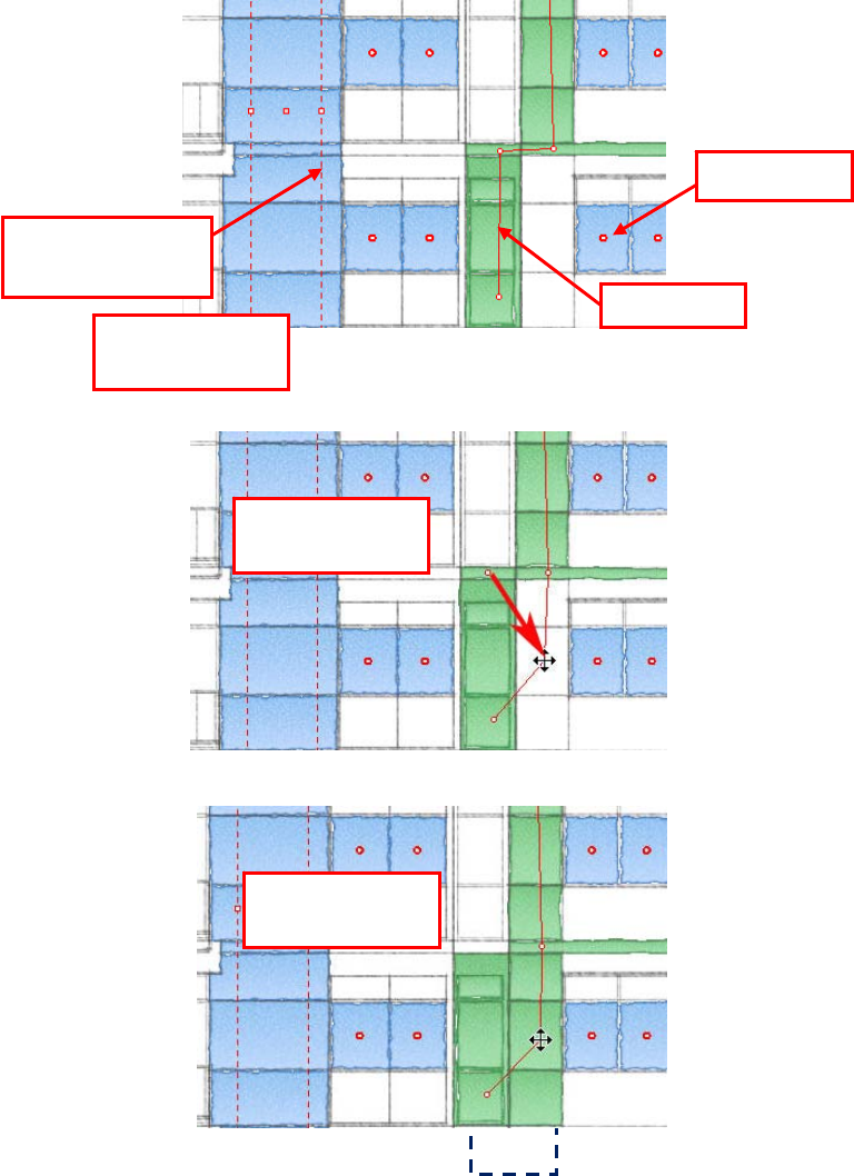
Area Fill Anchors
Area Fill anchors enable you to quickly change or edit filled areas. Suppose you have
filled a group of areas in the rendering, but after a CAD geometry update, you find that the
filled area has moved. Simply dragging a fill anchor to the new geometry automatically fills
in the new areas.
Depending on the method used for creating area fills, the anchors are displayed
differently.
Window Crossing
anchor
Point anchor
Line ancho
r
Crossed areas fill
automaticall
y
Figure 10. Using
Area Fill anchors
Drag an anchor
into an area…
…and affected
areas fill
AUTODESK IMPRESSION 2 FEATURE OVERVIEW
13
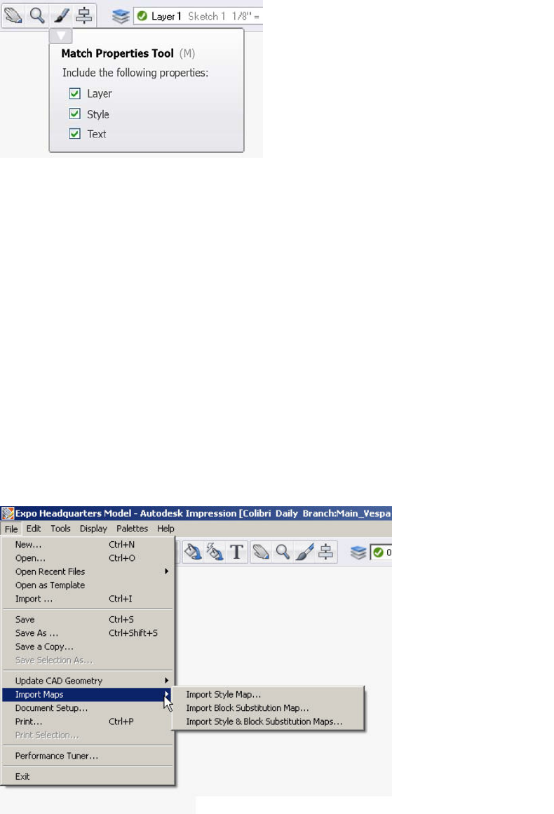
Match Properties
The Match Properties tool enables you to copy style, layer, and text properties from one
object in the canvas to another. It works with object types such as text, strokes, and
areas.
Stylizing Multiple Illustrations with Style Mapping
Want to quickly create several related illustrations that all have the same look and feel?
With Impression, you can quickly render a design by importing a style map from another
Autodesk Impression drawing. You then have two drawings with exactly the same look
and feel.
Let’s say that you create an illustration of a building elevation. It is likely that you will want
the other building elevations for that project or similar projects to have that same look.
Once you have stylized one of the elevations, you can use style mapping to apply the
style map from the first elevation to the second elevation—and automatically create
another rendered presentation image. For this to work, the two elevation DWG files must
have the same layer names. This is a powerful way to quickly stylize several different
drawings that have identical layer structures.
Note: To take advantage of style mapping, your original drawing should have a minimum
of style overrides.
Figure 11. Match Properties tool
Fi
g
ure 12. Im
p
ort St
y
le ma
p
AUTODESK IMPRESSION 2 FEATURE OVERVIEW
14
Blocks
Blocks are commonly used elements in CAD files. Blocks can save time and help
standardize drawings by minimizing the need to redraw standard components over and
over again. CAD blocks can vary in complexity and application.
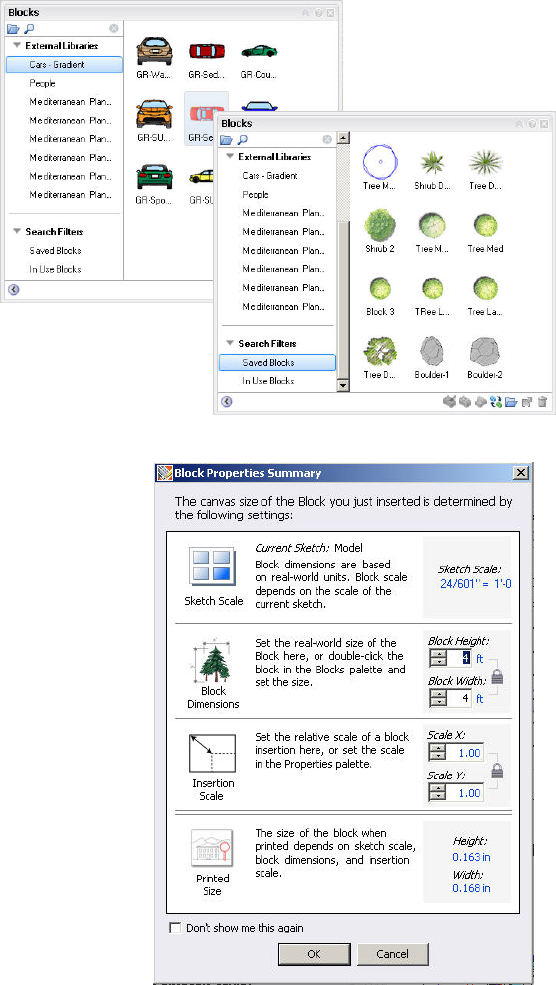
Adding Entourage Elements
Entourage elements are blocks that represent cars, people, or trees and shrubs. The
Impression block libraries are organized in external file folders sorted by theme. For
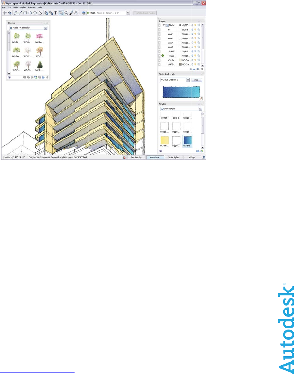
example, if a landscape plan needs some trees, from the Blocks palette you can navigate
to a library of tree blocks and import
the entire library, or you can import
individual blocks from another
Impression file.
Add entourage elements simply by dragging a block from
the Blocks palette onto the canvas. When you drag a
block into your illustration, the Block Properties Summary
palette displays useful, editable information about the
scale, real-world size, and printed size of the block that
you are inserting.
Figure 13. Block
library palettes
Figure 14. Block Properties Summary palette
AUTODESK IMPRESSION 2 FEATURE OVERVIEW
15
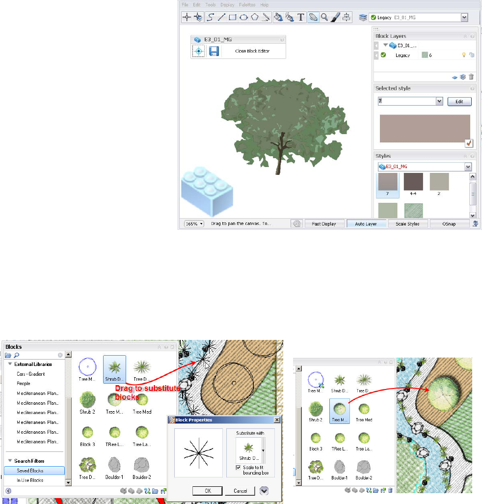
Block Editor
The Block Editor provides a streamlined, comprehensive way to edit blocks. When you
have a block selected, right-click, and select Edit Block to open the dedicated block
editing environment that mirrors the regular Impression workspace.
The Block Editor enables you to toggle
the visibility of the block insertion point
and save edits made to the block. A
block-shaped watermark in the lower left
corner of the Block Editor viewport
reminds you that you are in the Block
Editing environment.
Each block has unique layers and styles
that can only be accessed while in Block
Editing mode; however, they are still
accessed through the familiar Layer and
Styles palettes.
Block Substitution
Impression takes full advantage of DWG blocks. With Impression you can quickly replace
DWG block references with stylized blocks created in Impression. Simply drag a stylized
block from the Blocks palette onto any block on the canvas and all of the blocks with the
same name are updated. This is known as block substitution.
A history of substitutions in the drawing can be edited, and the original blocks can be
restored. This Block Substitution map can also be used with other files that use the same
block names, in the same way that you import style maps.
Figure 16. Substituting Impression
blocks for DWG blocks
Figure 15. Editing a block in
the Block Editor
AUTODESK IMPRESSION 2 FEATURE OVERVIEW
16
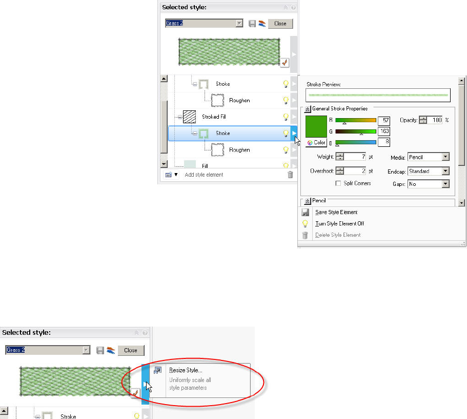
Editing Styles
While numerous styles are provided with Impression, there are an almost infinite number
of graphic styles and methods used to create nonphotorealistic renderings and
illustrations. You may want to create styles that meet your specific technique of rendering
or even create a custom “signature style” for a specific project or your firm as a whole.
You edit styles in the Style Editor. Elements of an appearance style are stacked in the
style tree. Each element has its own opacity setting, so you can accentuate certain
aspects of the style. Numerous controls modify color, hardness, end fade, and other
settings. Keep in mind that there is
no wrong way to make a style, so
you can build unique style libraries
for use on other projects.
To simultaneously scale all the settings in a specific style, click the Resize Style flyout
next to the style preview swatch.
Figure 17: Edit individual
Style elements in the
St
y
le Edito
r
Figure 18. Easily resize styles to match
desired scale
AUTODESK IMPRESSION 2 FEATURE OVERVIEW
17
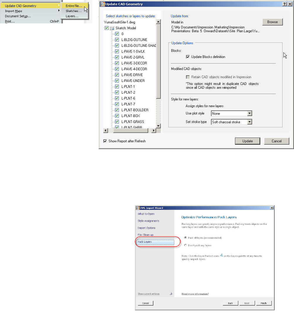
Updating Your CAD Geometry
If your CAD data changes in the original DWG file after you have stylized it in Impression,
you can easily bring the updated geometry into Impression.
As you are working on your illustration in Impression, chances are that you or someone
else is still editing the original CAD file. When you are ready to update your illustration
with the modified CAD geometry, choose Update CAD Geometry on the File menu. You
can update the entire drawing, only a sketch, or individual layers.
Performance Tuning
Impression renders linework with sophisticated effects. As a result, there are certain
things to consider when working with large or complex DWG files in order to extend
system performance.
Layer Packing
When opening a DWG file, the last panel of the
DWG Import wizard enables you to pack certain
objects on a layer into a single object. (To be
packed, they must have the same style and a
sequential draw order.) This not only enhances
performance but can also make managing styled
layers easier. A layer can be unpacked and
repacked at any time on the Layers palette or
Performance Tuner.
Figure 20.
DWG Import wizard
Figure 19.
Update CAD Geometry dialog box
AUTODESK IMPRESSION 2 FEATURE OVERVIEW
18
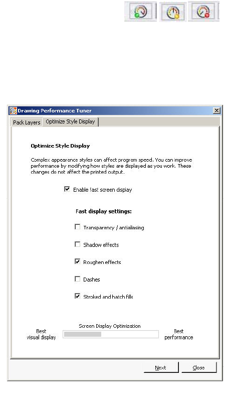
Performance Tuner
It is important to set up a drawing so that it will perform efficiently before you open it.
However, you might also make changes while working in Impression that could degrade
performance as your rendering progresses. The Performance Tuner monitors your
drawing and identifies instances when you can take action to improve performance.
At these times, the Performance Meter urges you to open the Drawing Performance
Tuner, where you can
Get a more informed understanding of what factors may be contributing to slow
performance
Take action to tune performance of the open drawing
Learn what affects performance so you can manage those factors more
successfully
The Drawing Performance Tuner features two tabs: one for
tuning the packed/unpacked state of the layers and one for
setting Fast Display mode, which hides certain elements such
as stroked fills or shadows as you work. Together, the settings
established in the two tabs of this dialog box determine the color
of the Performance Meter button. The Performance Meter is
updated as each setting changes, so you immediately see the
total effect of changes as they are made.
Pack Layers
Indicates the relationship between total objects and
performance
Indicates the importance of managing packing and
unpacking while demonstrating its benefits
Provides a quick way to restore a packed state
Optimize Style Display
Indicates the cost of style complexity
Indicates the performance costs of using styles with
certain characteristics
Hides visual elements as you work (Fast Mode) to
preserve performance (does not affect final output)
Sharing Impression Images
Impression documents are saved in the IRF file format. Impression files include drawing
information from the original CAD drawing, plus the Impression stylizations, layers,
objects, blocks, and so on.
Impression illustrations can be saved as DWF files, viewable with Autodesk® Design
Review and Autodesk® DWF™ Viewer application. They can also be saved into a several
file formats popular in the desktop publishing world, including PSD, the native Adobe®
Photoshop® format; EPS, the standard for embedding graphics in page layout
applications; PDF, for electronic document sharing; and a variety of popular image file
formats such as PNG, JPEG, and BMP.
Figure 21.
Performance Meter
Figure 22. Drawing Performance Tuner
AUTOD
E
Impress
i
to E siz
e
Mo
r
The foll
o
Impr
e
The Imp
becomi
n
the late
s
•
•
•
•
Com
m
Stay inf
o
Commu
n
Occasiona
products a
products,
s
not be ma
d
forward-lo
o
they were
m
and is not
r
Autodesk,
other coun
© 2008 Au
E
SK IMPRES
S
i
on illustration
s
e
sheets, with r
r
e Re
s
o
wing resourc
e
e
ssion Co
ression Com
m
n
g a member o
f
s
t resources a
v
Content sh
a
Member dis
Blogs and
w
Tips submit
t
m
unicatio
o
rmed about e
v
n
ication Cente
r
lly, Autodesk mak
e
nd services. Thes
e
s
ervices, or feature
d
e based upon reli
a
o
king statements t
o
m
ade. Autodesk r
e
r
esponsible for typ
o
AutoCAD, DWF, a
tries. All other bra
n
todesk, Inc. All rig
h
S
ION 2 FEATU
s
can be printe
d
esolutions up
t
s
ource
s
s provide mor
e
mmunity
m
unity website i
f
the Autodesk
v
ailable. Benefi
t
a
ring
cussions
w
ebcasts
t
ed by other I
m
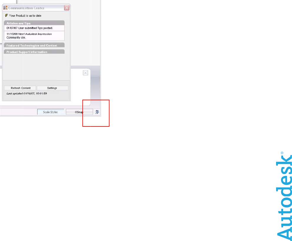
n Center
v
erything from
r
.
e
s statements rega
e
statements are n
o
s but merely refle
c
a
nce on these stat
e
o
reflect events tha
t
e
serves the right to
o
graphical or grap
h
nd DWG are regis
t
n
d names, product
h
ts reserved.
RE OVERVIE
W
d
on all page s
t
o 300 dpi.
s
e
information a
s located at ht
Impression C
o
t
s of members
m
pression user
s
software upda
t
To set
u
Impres
s
your co
prefer f
o
channe
To ope
n
Comm
u
right si
d
rding planned or f
u
o
t intended to be a
c
t our current plans
,
e
ments. The Com
p
t
occur or circumst
alter product offer
i
h
ical errors that m
a
t
ered trademarks o
names, or tradem
a
Fi
g
Th
e
W
izes supporte
d
bout Autodes
k
tp://impressi
o
o
mmunity, you
hip include ac
c
s
t
es to new tut
o
u
p the Commu
s
ion, use the
W
untr
y
or regio
n
o
r updates, an
d
ls you want di
s
n
the Commun
u
nication Cent
e
d
e of the statu
s
u
ture development
promise or guara
n
,
which may chang
p
any assumes no
o
ances that exist or
i
ngs and specificat
i
a
y appear in this d
o
r trademarks of A
u
a
rks belong to thei
r
g
ure 23.
e
Communica
d
by standard
p
k
Impression s
o
o
n.autodesk.c
o
can stay curr
e
c
ess to
o
rials by tuning
nication Cente
W
elcome wizar
d
n
, the frequenc
y
d
the informati
o
s
played.
ication Center
,
e
r icon in the tr
s
bar.
efforts for our exis
t
n
tee of future deliv
e
e. Purchasing dec
i
o
bligation to updat
e
change after the
d
i
ons at any time wi
t
o
cument.
u
todesk, Inc., in the
r
respective holder
s
tion Cente
r
p
lotters up
o
ftware.
o
m. By
e
nt with all
in to the
r in
d
to select
y
you
o
n
,
click the
ay on the
t
ing or new
e
ry of
i
sions should
e
these
d
ate on which
t
hout notice,
USA and/or
s
.
19
