H3 SYSTEM H3G-650 CDMA Gateway User Manual CDMA Gateway Instruction R0 01
H3 SYSTEM Co., Ltd. CDMA Gateway CDMA Gateway Instruction R0 01
Users Manual
CDMA Gateway Instruction
(H3G-650)
H3 System Co., Ltd

< Revision Notes >
No. Date Version Content Author
0. Overview
This document describes instructions regarding the H3 CDMA gateway (H3G-650, H3
System) and the related components. This document includes
- How to install and configure the H3 CDMA gateway
- How to use the H3 CDMA gateway
- How to setup a server system for the H3 CDMA gateways
1. Gateway installation
1) Preparation for deployment
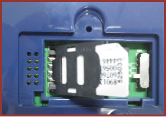
A. SIM card
i. Unscrew and open the bottom cover.
And insert a SIM card.
B. Gateway configuration
i. Turn off the gateway.
ii. Connect a serial cable (provided by H3
System) to a gateway and a PC.
iii. Run the configuration software.
iv. Turn on the gateway.
v. Configure the gateway with the configuration software. For the details, please
see the section below, “Gateway configuration.”
C. Pairing and testing
i. Pair with devices. Please see “Pairing” section below.
ii. Take readings and confirm if the readings are successfully delivered to a server.
Please see “Measurement and data transmission” section.
D. Final inspection
i. Confirm the mode selection switch at “N.” If not, set the switch at “N.”
ii. Prepare dry cells for backup batteries.
iii. Close the bottom cover.
2) Installation at user’s home
A. Place a gateway at a suitable place.
B. Connect a power adapter.
C. Insert dry cells if required.
2. Gateway configuration
1) Components
A. A serial cable provided by H3 System
B. Configuration software
i. For admin: Serial numbers can be modified.
ii. For user: Serial number change is not allowed.
2) Descriptions
Figure 1. SIM card insertion
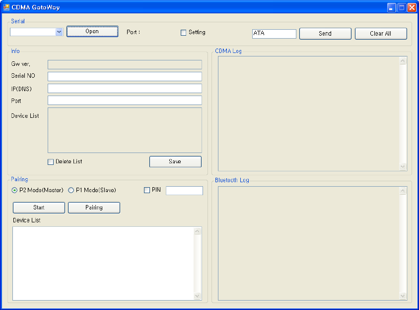
A. Configuration software for an admin: Serial No. modification is enabled.
B. Items
i. Open: Open the serial port
ii. Setting: Shall be checked for changing gateway configurations
iii. Serial No: Serial number of the gateway. It’s only enabled for the Admin
version
iv. IP(DNS): DataCollection Server IP or DNS
v. Port: DataCollection Server port
vi. Devices List: List of paired devices. Types and BT addresses.
vii. Delete List: Delete all pairing info.
viii. Clear Button: Clear window
ix. Send Button: Send a new configuration to the gateway
x. CDMA Log: CDMA AT-command logs
3) Steps
A. Turn off the gateway.
B. Connect a serial cable (provided by H3 System) to a gateway and a PC.
C. Run the configuration software.
D. Select the suitable COM port (You can check the COM port at the device manager.)
and click “Open.”
E. If you want to modify configuration, then check “Setting.” Otherwise uncheck
“Setting.”
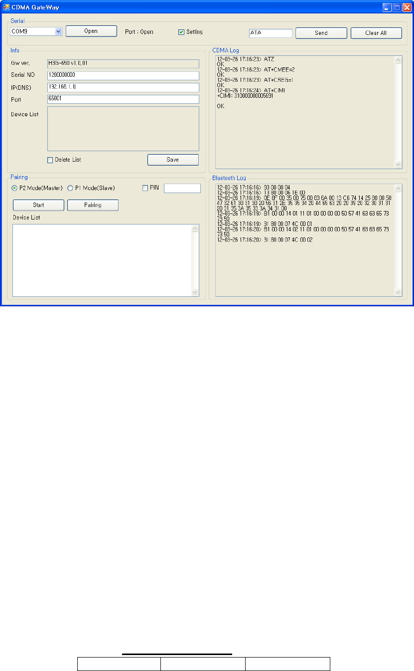
F. Turn on the gateway.
G. The current configuration and paired devices info are shown.
H. Change the parameters and click “Send.”
I. If you want to delete the pairing info, check “Delete List” and click “Send.”
J. Before clicking “Send”, please double check the settings.
K. Turn off the gateway and disconnect the serial cable.
3. Pairing
1) Mode selection switch
A. “N”: Normal operation mode
B. “P1”: Pairing mode as a slave. Used for A&D weighing scale (UC-321PBT) and
blood pressure monitor (UA-767PBT).
C. “P2”: Used for GMA (BA-100) for Lifescan’s blood glucose meter (OneTouch Ultra,
OneTouch Mini/Easy, OneTouch Ultra2), IEM blood pressure monitor (Stabil-O-
Graph), ForaCare’s thermometer (FORA IR20b), and Beijing Choice’s Pulse
Oximeter(MD300C318).
2) Pairing process
A. General process
i. Turn off the gateway.
ii. Set the mode selection switch at suitable mode.
iii. Let the device be at pairing mode.
iv. Turn on the gateway.
v. The gateway shows the number of currently paired devices with LEDs for 5
seconds. (Even at the mode “N”)
Number of paired SENDING LED READING LED

devices
0 Off Red On
1 Green On Off
2 Green On Green On
3 Green On Red On
4 Red On Off
5 Red On Green On
vi. During pairing process, the “Readings” LED turns GREEN.
vii. At successful pairing, the “Readings” LED blinks GREEN 5 times.
viii. At failure, the “Readings” LED blinks RED 5 times.
ix. The gateway goes to the step “v.”
x. You can pair another device at the same pairing mode successively.
xi. After completion of pairing, you should turn off, set the mode selection
switch at “N” and turn on the gateway for normal operation.
xii. It is strongly recommended that you pair all devices even when you want to
pair one device.
xiii. For failure, just let the device at pairing mode and find the result. (Step
“vii” and “viii”) Don’t turn off the gateway and restart the whole
procedure again.
B. Pairing A&D’s blood pressure monitor and weighing scale
i. Turn off the gateway that the measuring device paired with before if exists.
ii. Set the mode selection switch at “P1.”
iii. Turn on the gateway.
iv. The gateway shows the number of currently paired devices with LEDs for 5
seconds.
v. The “Readings” LED turns GREEN.
vi. Take a reading with the blood pressure monitor or weighing scale.
vii. At success, the “Readings” LED blinks GREEN 5 times.
viii. At failure, the “Readings” LED blinks RED 5 times.
ix. The gateway goes to the step “iv.”
x. You can pair another device at P1 mode successively.
xi. After completion of pairing, you should turn off, set the mode selection switch
at “N” and turn on the gateway for normal operation.
C. Pairing GMA (BA-100).
i. Set the mode selection switch at “P2.”
ii. Let the GMA be at pairing mode.
iii. Turn on the gateway.
iv. The gateway shows the number of currently paired devices with LEDs for 5
seconds.
v. The “Readings” LED turns GREEN.
vi. Wait for about a few minutes.
vii. At success, the “Readings” LED blinks GREEN 5 times.
viii. At failure, the “Readings” LED blinks RED 5 times.
ix. The gateway goes to the step “iv.”
x. You can pair another device at P2 mode successively.
xi. After completion of pairing, you should turn off, set the mode selection switch
at “N” and turn on the gateway for normal operation.
D. Pairing IEM’s blood pressure monitor
i. Turn off all mobile devices nearby, especially Bluetooth.
ii. Set the mode selection switch at “P2.”
iii. Let the IEM’s blood pressure monitor at pairing mode.
iv. Count 30 seconds.
v. Turn on the gateway.
vi. The gateway shows the number of currently paired devices with LEDs for 5
seconds.
vii. The “Readings” LED turns GREEN.
viii. Wait for about a few minutes.
ix. At success, the “Readings” LED blinks GREEN 5 times.
x. At failure, the “Readings” LED blinks RED 5 times.
xi. The gateway goes to the step “v.”
xii. You can pair another device at P2 mode successively.
xiii. After completion of pairing, you should turn off, set the mode selection switch
at “N” and turn on the gateway for normal operation.
E. Pairing ForaCare’s thermometer
i. Set the mode selection switch at “P2.”
ii. Take a reading with the thermometer.
iii. Turn on the gateway.
iv. The gateway shows the number of currently paired devices with LEDs for 5
seconds.
v. The “Readings” LED turns GREEN.
vi. Wait for about a few minutes.
vii. At success, the “Readings” LED blinks GREEN 5 times.
viii. At failure, the “Readings” LED blinks RED 5 times.
ix. The gateway goes to the step “iv.”
x. You can pair another device at P2 mode successively.
xi. After completion of pairing, you should turn off, set the mode selection switch
at “N” and turn on the gateway for normal operation.
F. Pairing Beijing Choice’s Pulse oximeter
i. Set the mode selection switch at “P2.”
ii. Take a reading with the oximeter.
iii. When the Bluetooth icon of the oximeter flashes, remove the finger.
iv. Turn on the gateway.
v. The gateway shows the number of currently paired devices with LEDs for 5
seconds.
vi. The “Readings” LED turns GREEN.
vii. Wait for about a few minutes.
viii. At success, the “Readings” LED blinks GREEN 5 times.
ix. At failure, the “Readings” LED blinks RED 5 times.
x. The gateway goes to the step “v.”
xi. You can pair another device at P2 mode successively.
xii. After completion of pairing, you should turn off, set the mode selection switch
at “N” and turn on the gateway for normal operation.
3) Pairing
A. General process
i. P2 Mode(Master): The same mode as “P2” mode with the mode selection
switch
1. Go to configuration mode. Please see the section “2. Gateway
configuration” with “setting” checked.
2. Click “Start” for searching devices. As the result, a list of Bluetooth
devices available is shown in “Device List.”
3. Select one device and click “Pairing.”
4. Information about the process will be shown in “Bluetooth Log.”
ii. P1 Mode(Slave): The same mode as “P1” mode with the mode selection switch
1. Go to configuration mode. Please see the section “2. Gateway
configuration” with “setting” checked.
2. Click “Start” to make gateway be pairing standby mode.
3. Information about the process will be shown in “Bluetooth Log.”
4. Measurement and data transmission
1) How to use
A. Take a reading, and then the reading is transmitted to the gateway by Bluetooth.
B. And the reading is automatically transmitted to the server via mobile networks.
C. At server access failure, it tries 9 more times, in total 10 times at most with 1 hour
period until success.
2) Clock setup
A. Clock of the gateway is automatically set with CDMA connection.
B. Clocks of measuring devices can be set during communication with the gateway.
C. But, regarding the IEM’s blood pressure monitor, clock must be set manually.
3) LED indications
A. During Bluetooth communication, the “Readings” LED turns GREEN.
B. At success, the “Readings” LED blinks GREEN 5 times.
C. At failure, the “Readings” LED blinks RED 5 times.
D. During server connections, the “Sending” LED turns GREEN.
E. At success, the “Sending” LED blinks GREEN 5 times.
F. At failure, the “Sending” LED blinks RED 5 times.
4) Notification for power failure
A. The gateway is supposed to connect to a server when an AC adapter is connected
and disconnected.
B. It sends “Power up” and “Power down” signals, respectively.
C. Backup batteries are required.
5) Heart beat
A. Server access is taken every six hours for indication “I’m alive.”
B. If there is any reading unsent, the reading is sent to a server together.
5. Data collection software
1) Setup
A. Default path :
C:\Program Files\H3SYSTEM\DataCollection_GPRS\DataCollection_GPRS.exe
B. Configuration file name: gprs_config.ini
C. Contents of configuration file (gprs_config.ini)
i. LOG_PATH=C:\gprs\log <= Log file path
ii. DATA_PATH=C:\gprs\data <= Data XML file path
iii. PORT=65001 <= TCP/IP port
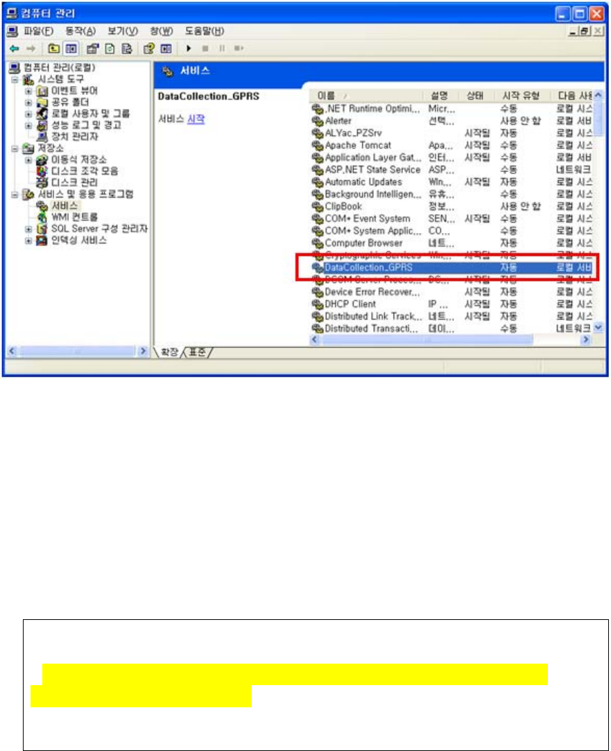
D. Change of configuration
i. Stop the corresponding windows service
ii. Change the configuration file, gprs_config.ini
iii. Re-start the windows service
E. To start the windows service: At “Windows Service”, select “DataCollection_GPRS”
and run.
2) Data files and communication log files
A. Data XML files will be generated at the folder defined at “DATA_PATH.”
B. Log files will be generated at the folder defined at “LOG_PATH.”
C. Examples
Ex) Data XML file name: H3_20101004194422_1111111111.xml
Creation logic of xml file name: Datetime + gateway serial no
Ex) Log file name: H3_20101004194422_156.log
Creation logic of log file name: Datetime
6. XML file
<?xml version="1.0" encoding="utf-8"?>
<Measure serial="1111000002" dc="1" battery="1.2">
<Info servertime="20111221132941" gwtime="20111221132941" sim="310260760561444"
fw="H3G-700 v1.0.28" signal="99,99" />
<Device type="Pressure_AND">
<Data id="5080600120" measuretime="20111109132941" sys="155" dia="98" pul="77"

battery="2.63"
con_gwtime="20111221132941" con_devtime="20111221132941" />
</Device>
<Device type="Weight">
<Data id="2222222201" measuretime="20110901142303" result="068.60" unit="kg" battery="2.3"
con_gwtime="20111221132941" con_devtime="20111221132941" />
</Device>
<Device type="Glucose">
<Data id="ZHZ3064BY" measuretime="20111109142303" result="463" unit="0" model="1"
adapter="1"
con_gwtime="20111221132941" con_devtime="" />
</Device>
<Device type="Glucose">
<Data id="ZHZ3064BY" measuretime="20111109142303" result="463" unit="0" model="1"
adapter="2" battery="3.0" con_gwtime="20111221132941" con_devtime="" />
</Device>
<Device type="Thermometer">
<Data id="00123E0019B5" measuretime="20100101001000" otemp="97.88" btemp="83.66"
unit="F" />
</Device>
<Device type="Pressure_IEM">
<Data id="61102DM2" measuretime="20110215151641" sys="157" dia="100" pul="091"
con_gwtime="20111221132941" con_devtime="20111221132941" />
</Device>
<Device type="OXI">
<Data id="0018E41E7B7F" measuretime="20100116012117" pid="001" temp="000" pr="075"
spo2="90"
battery="10" con_gwtime="20111221132941" con_devtime="" />
</Device>
<Device type="OXI">
<Data id="0018E41E7B7F" measuretime="20100116012117" pid="001" temp="000" pr="075"
spo2="90" battery="10"/>
</Device>
</Measure>
Item Description
Common serial="2222222222" GateWay Serial No
dc="0" Power Adapter Connection Status ( 0 :
Connected ,1 : unconnected)
battery="1.2" Gateway battery
type="glucose" Device
- Glucose : Glucometer
- Pressure_AND : Blood pressure(AND)

- Pressure_IEM : Blood pressure(IEM)
- Weight : weight scale(AND)
- Thermometer : Thermometer
- OXI : Pulse Oximeter
id="ZHZ306CBY" Device Serial No
measuretime="20100101001250" Measurement time
con_gwtime="20111221132941" Gateway's time stamp during communication
between the measuring device and gateway
con_devtime="20111221132941"Measuring device's time stamp during
communication between the measuring device
and gateway
(If the measuring device supports sending
device's current time)
Glucometer result="103" Measurement value
unit="0" Unit (0 : mg/dL, 1 : mmol/L)
model="1" Glucometer Model (0:Ultra, 1:Ultra2,
2:Mini/Easy)
adapter="1" Glucometer Adapter (0 : N/A, 1: BA-100, 2:
BA-110)
battery="3.0" Battery level (only for BA-110)
BP Monitor
(AND)
sys="139" Systolic
dia="091" Diastolic
pul="094" Pulse rate
battery="2.63" Battery
Weight
Scale
result="066.80" Measurement value
unit="kg" Unit (kg or lb)
battery="2.32" Battery
Thermometer otemp=”98.42” Object Temperature (Body temperature)
btemp=”74.84” Back-ground temperature (Outside temperature)
unit=”F” Unit (F : Fhar)
BP Monitor
(IEM)
sys="157" Systolic
dia="100" Diastolic
pul="091" Pulse rate
Oximeter pid="001" PID
temp="000" Temperature
pr="075" Pulse rate
spo2="90" Spo2
battery="10" Battery level (Unit: %)
10 for less than 10%
Gateway
information <Info
servertime="20111221132941"
gwtime="20111221132941"
sim="310260760561444"
fw="H3G-700 v1.0.28"
signal="99,99" />
servertime: timestamp of DataCollection Server
during communication between gateway and
server
gwtime: timestamp of gateway during
communication between gateway and server
sim: SIM card ID including carrier info
fw : GateWay firmware version
signal: signal strength (format : signal=”rssi,
ber”)
Regulatory Statements to be included in the Users Guide for Sputnik
USA-Federal Communications Commission (FCC)
This device complies with part 15 of the FCC Rules. Operation is subject to the following
two conditions: (1) This device may not cause harmful interference, and (2) this device
must accept any interference received, including interference that may cause undesired
operation.
This equipment has been tested and found to comply with the limits for a Class B digital
device, pursuant to Part 15 of FCC Rules. These limits are designed to provide reasonable
protection against harmful interference in a residential installation. This equipment
generates, uses, and can radiate radio frequency energy. If not installed and used in
accordance with the instructions, it may cause harmful interference to radio
communications. However, there is no guarantee that interference will not occur in a
particular installation.
If this equipment does cause harmful interference to radio or television reception, which
can be determined by tuning the equipment off and on, the user is encouraged to try and
correct the interference by one or more of the following measures:
-Reorient or relocate the receiving antenna
-Increase the distance between the equipment and the receiver.
-Connect the equipment to outlet on a circuit different from that to which the receiver is
connected.
-Consult the dealer or an experienced radio/TV technician for help.
Any changes or modifications not expressly approved by the party responsible for
compliance could void the user’s authority to operate the equipment.
Caution: Exposure to Radio Frequency Radiation.
1. This device and its antenna must not be co-located or operating in
conjunction with any other
antenna or transmitter. To maintain compliance with FCC RF exposure
guidelines for bodyworn
operation, do not use accessories that contain metallic components.
2. This equipment complies with FCC RF radiation exposure limits set
forth for an uncontrolled environment. This equipment should be
installed and operated with a minimum distance of 20 centimeters
between the radiator and your body.