HAC Telecom Technology HAC-LBEE Zigbee Module User Manual HAC LBee Manual V3 2 2 3 Rev1
Shenzhen HAC Telecom Technology Co. Ltd. Zigbee Module HAC LBee Manual V3 2 2 3 Rev1
User manual
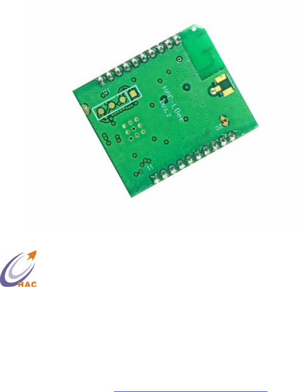
HAC-LBee
2.4G Low Power Consumption
Wireless Data Transmission Module
(ZigBee Protocol)
V 32.23.33 2013/11/07
User Manual
SHENZHEN HAC TELECOM TECHNOLOGY CO., LTD
Add: Fl.6, Building 2, Jiuxiangling New Industry Park, No.4227,
Xilihu Road, Nanshan, Shenzhen, China.
Tel : +86-755-23981078
Fax : +86-755-23981007
Email : webmaster@rf-module-china.com
Web : http://www.rf-module-china.com
¾ High Performance
20dbm, 3.5Km (LOS, light of sight)
¾ Low Power Consumption
Transmitting current: 150mA @ 20dBm
Receiving current: 30mA @ 20dBm
Sleep current: 3µA @ 20dBm
¾ MESH Network
Self-organizing, Self-routing, Self-healing
Point-to-point and Point-to-multipoint Transmission
¾ Simply To Use
AT, API AT, Remote API AT command
Transparent mode, API mode
¾ Standards
Zigbee 2007 PRO
¾ High Reliability
DSSS O-QPSK modulation
CSMA-CA Automatic Backoff Mechanism
Re-transmission and Response Mechanism
¾ High Security
AES Encryption for Network Layer
AES Encryption for Application Layer
Catalog
I.HAC-LBEE MODULE..................................................................................................................5
1 THE SIZE AND PIN ORDER OF LBEE MODULE.....................................................................................5
2 PIN DEFINITION..................................................................................................................................5
3 TECHNICAL PARAMETERS...................................................................................................................6
II.HAC-LBEE MODULE OPERATION .........................................................................................7
1 UART PORT INSTRUCTION...............................................................................................................7
2 COMMUNICATION PROTOCOL .............................................................................................................7
2.1 Transparent Mode ......................................................................................................................7
2.2 API Mode ...................................................................................................................................7
3 AT COMMAND MODE .........................................................................................................................7
3.1 Enter AT Command Mode..........................................................................................................8
3.2 Send AT Command.....................................................................................................................8
3.3 AT Command Response..............................................................................................................8
3.4 Exit AT Command Mode ............................................................................................................8
III.API OPERATION......................................................................................................................9
1 API FRAME FORMAT ..........................................................................................................................9
2. API FRAME .......................................................................................................................................9
2.1. Local AT Command Frame .......................................................................................................9
2.2. Response Frame for Local AT Command................................................................................10
2.3. Request Frame for Remote AT Command ............................................................................... 11
2.4. Response Frame for Remote AT Command.............................................................................12
IV.AT COMMAND .......................................................................................................................14
1 ADDRESS COMMAND........................................................................................................................14
2 NETWORK COMMAND ......................................................................................................................14
3 RF PARAMETER COMMAND..............................................................................................................16
4 SERIAL PORT PARAMETER COMMAND..............................................................................................16
5 I/O PARAMETER COMMAND .............................................................................................................17
6 DIAGNOSTICS PARAMETER COMMAND.............................................................................................17
7 AT COMMAND PARAMETER..............................................................................................................18
8 SLEEP COMMAND.............................................................................................................................18
9 EXECUTE COMMAND........................................................................................................................19
V. LBEE ZIGBEE NETWORK.......................................................................................................20
1 COORDINATOR..................................................................................................................................20
2 ROUTER............................................................................................................................................20
3 ENDDEVICE......................................................................................................................................21
3.1 The Relationship between Father node and Child node...........................................................21
3.2 Child Node Capability..............................................................................................................21
4 WORKING PROCESS FOR CHILD NODE..............................................................................................22
5 WORKING PROCESS FOR FAT HE R NODE............................................................................................22
ANNEX
FCC WARNING STATEMENT.......................................................................... 错误!未定义书签。
FCC RADIATION EXPOSURE STATEMENT................................................ 错误!未定义书签。
...........................................................................................................................................23
I. HAC-LBee Module
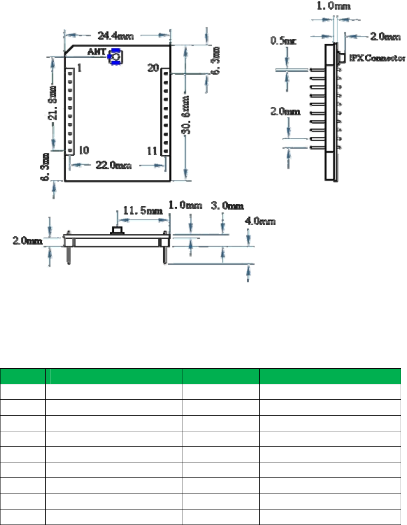
1 The Size and Pin Order of LBee Module
Pin Order: From PIN1 to PIN20, Anticlockwise.
2 Pin Definition
Pin No. Definition Default State Function instruction
1 VCC Power supply
2 TXD Output UART data output
3 RXD Input UART data input
4 DIO1 Input/output GPIO1, RS485 Enable
5 RESET Input Low level reset
6 DIO2 Input/output GPIO2
7 DIO3 Input/output GPIO3
8 DIO4/DD Input/output GPIO4/Programming data
9 DIO5/DC Input/output GPIO5/Programming

Clock/Sleep function enable
10 GND Ground
11 DIO6 Input/output GPIO6
12 DIO7 Input/output GPIO7
13 DIO8 Input/output GPIO8
14 DIO9 Input/output GPIO9
15 DIO10 Input/output GPIO10
16 DIO11 Input/output GPIO11
17 DIO12 / ADC3 Input/output
GPIO12 / Analog Input 3
18 DIO13 / ADC2 Input/output
GPIO13 / Analog Input 2
19 DIO14 / ADC1 Input/output
GPIO14 / Analog Input 1
20 DIO15 / ADC0 Input/output
GPIO15 / Analog Input 0
3 Technical Parameters
HAC-LBee Parameter Name
Minimum Typical Value Maximum
Unit
Electric Performance (25℃)
Power Supply 3.0 3.3 3.6 V
Interface Level -0.3 VCC+0.3≤3.6 V V
Transmitting Current 140 150 160 mA
Receiving Current 29 30 31 mA
Sleeping Current 3 μA
Wireless Performance(25℃)
Working Frequency 2.405 2.485
GHz
Transmitting Power 19.0 19.5 20.2
dBm
Receiving Sensitivity -107 dBm
RF Data Rate 250 Kbps
General Performance
Interface baud rate 1200 9600 115200
bps
Working Temperature -40 80 ℃
Distance (LOS) 3500 m
II. HAC-LBee Module Operation
1 UART Port Instruction
LBee module is controlled through the UART port. Please refer to the pin definition for more
information.
In the actual operation, users need to pay attention to that, the external controller should have
the same setting (including the baud rate, parity and stop bit) as the UART port of LBee module.
The default baud rate is 38400bps, users can use ‘DB’ command to set it. The default parity is
no parity, users can use ‘NB’ command to set it.
2 Communication Protocol
LBee module support transparent mode and API mode.
2.1 Transparent Mode
Under the transparent mode, LBee module will not deal with the data from UART port, i.e. it
transmits any data from the UART_RX port to the air and output the receiving air data from the
UART_TX port.
The transparent mode can be set by AT command, set ‘AP = 0’ and exit the AT command
mode, i.e. it will enter the transparent mode. Please pay attention to that, when it is in the API
mode, the ‘AP = 1’.
2.2 API Mode
When LBee module works under the API mode, its UART port should send or receive the
data according to the definite frame format. The API mode also can be set by AT command, set
‘AP = 1’ and exit the AT command mode, it will enter the API mode. Under this mode, users can
interchange some parameters of network layer.
Under API mode, users can add the destination address and data load info into the sending
data frame, in this way, there is no need to use command to set these parameters. In the same way,
the receiving data frame includes the state info, source address and data load info, which is more
convenient for dealing with.
3 AT Command Mode
Under some cases, users have to use the AT command for operation, for example, convert the
transparent mode into the API mode. AT command can be used to read or set the parameters of
LBee module. Under the AT command mode, the receiving characters from the UART_RX port of
LBee module is interpreted as commands.
The AT command operating steps are shown as follow:
3.1 Enter AT Command Mode
Input 3-character command sequence ‘+++’, LBee module will enter the AT command mode.
When inputting, please pay attention to the ‘+’ interval. Once LBee module enters the AT
command mode, it will active a timeout timer, if there is no effective AT command input within
the timeout, it will exit the AT command mode automatically. So when inputting every effective
AT command, the timer will re-start for calculating.
3.2 Send AT Command
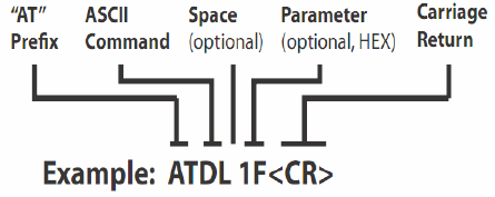
AT command is sent according to the following format.
If the AT command does not include the parameter, it is used to read the parameter value of
this command. If the AT command includes the parameter, it is used to set the parameter value of
this command. In the above example, it means that set the ‘DL’ value as ‘0x1F’. Note: the
parameter is in hex format.
Note: when changing the parameter, to keep using the changed parameter after reset, users
should use the ‘ATWR’ command to write the changed parameter into Flash to avoid value lost
caused by power off.
3.3 AT Command Response
When LBee module receives the AT command, it will analyze and execute the command. If
the command has been executed successfully, it will output ‘OK’ through UART_TX port. Under
the following situations, it will output ‘ERROR’, i.e. a. The parameter setting range is wrong. b.
The reading command goes with parameter value. c. The command is not executed correctly.
3.4 Exit AT Command Mode
Users can use the following ways to exit AT command mode:
A. Send ATCN command
B. There is no effective AT command within the set time.

III. API Operation
API mode is sending or receiving data according to the data frame. The API mode will point
out how to interchange the command, command response and state info through UART port of
LBee module.
1 API Frame Format
When ‘AP = 1’ and exit the AT command mode, LBee module will enter the API mode. The
API frame format is shown as follow:
0x7E: Start Delimiter, the head of frame
Length: 2 bytes, the length of frame data, excluding 0x7E, itself and parity byte.
Frame Data: Different types’ frames have different formats. It is listed in the following.
Checksum: Excluding 0x7E and length, add all bytes of Frame Data, keep only the lowest 8
bits of the result and subtract from 0xFF, then you will get the checksum. When verifying,
excluding 0x7E and length, add all bytes keeping only the lowest 8 bits of the result,
then plus the checksum. If the sum is equal 0xFF, and the checksum is correct.
Note: In the above field, if there are multi bytes, please send by big-endian format.
Every frame should start from 0x7E, so LBee module will discard the data before 0x7E and
will not deal with them. If the receiving data frame is not correct, for example the byte length is
wrong or the parity is wrong, LBee module will not deal with them neither.
2. API Frame
Different frame types have different frame structures. The detailed instruction for various
frame structure are shown as follow:
2.1. Local AT Command Frame
This API frame’s function is same as the AT command under the AT command mode, it is
used to set or check the parameters of local module. Users can use this API frame to set AT
command. The API frame structure is shown as follow:
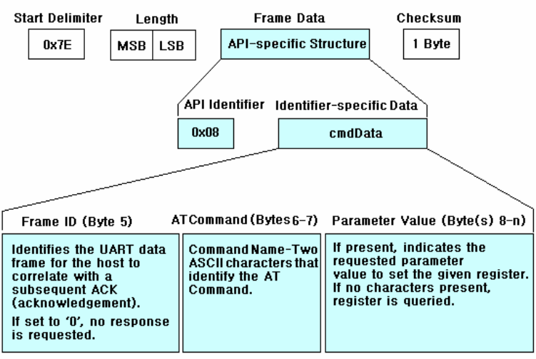
Start Delimiter: 0x7E
Length: Excluding the start delimiter, itself and parity
Frame type: 0x08
Frame ID: When there are many frames, the frame ID can used to indentify the frame. If the
frame ID is ‘0’, the LBee module will not respond.
AT Command: Currently, all AT commands are only 2 characters, for example ‘DL’, ‘ID’ etc.
It is the ASCII value of the AT command letter.
Parameter Value: If AT command goes with parameter, it means to set the parameter, if going
without parameter, and it means to read the parameter.
Checksum: Excluding 0x7E and length, add all bytes of Frame Data, keep only the lowest 8
bits of the result and subtract from 0xFF, then you will get the checksum.
2.2. Response Frame for Local AT Command
When inputting correct AT command frame, LBee module will output the response frame for
AT command. Some commands output multi-frame, such as ND command. The API frame
structure is shown as follow:
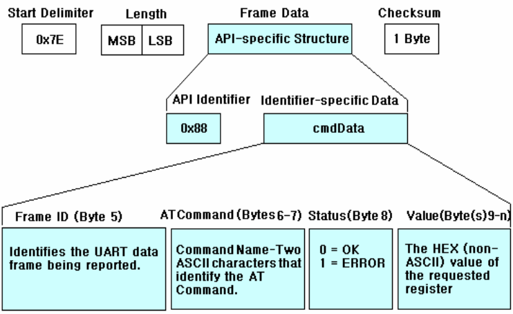
Start Delimiter: 0x7E
Length: Excluding the start delimiter, itself and parity
Frame type: 0x88
Frame ID: This ID is the one in the AT command frame If the frame ID is ‘0’, the LBee
module will not respond.
AT Command: Currently, all AT commands are only 2 characters, for example ‘DL’, ‘ID’ etc.
It is the ASCII value of the AT command letter.
Parameter Value: If the AT command is check command, it goes with parameter. If it is set
command, it goes without parameter.
Checksum: Excluding 0x7E and length, add all bytes of Frame Data, keep only the lowest 8
bits of the result and subtract from 0xFF, then you will get the checksum.
2.3. Request Frame for Remote AT Command
Comparing with AT command frame, the request frame for remote AT command is used to
check or set the parameters of remote module, not the local module. Its frame structure is shown
as follow:
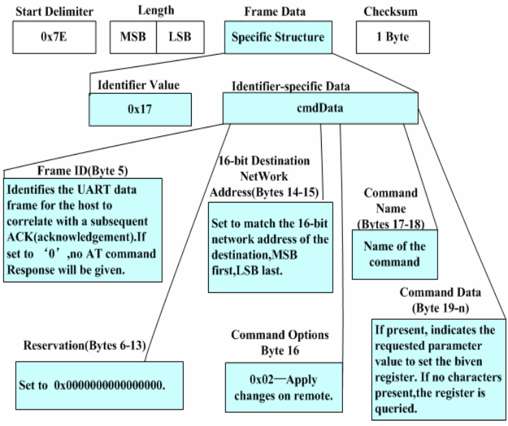
Start Delimiter: 0x7E
Length: Excluding the start delimiter, itself and parity
Frame type: 0x17
Frame ID: When there are many frames, the frame ID can used to indentify the frame. If the
frame ID is ‘0’, the LBee module will not respond.
64-bit Destination Address: The MAC address of the destination device, it is 64 bits. If it is
‘0x000000000000FFFF’, it is the broadcasting address, i.e. broadcast data.
16-bit Destination Address: The network address of the destination device, it is 16 bits. If it is
‘0xFFFF’, it is the broadcasting address, i.e. broadcast data.
AT Command: Currently, all AT commands are only 2 characters, for example ‘DL’, ‘ID’ etc.
It is the ASCII value of the AT command letter.
Parameter Value: If AT command goes with parameter, it means to set the parameter, if going
without parameter, and it means to read the parameter.
Checksum: Excluding 0x7E and length, add all bytes of Frame Data, keep only the lowest 8
bits of the result and subtract from 0xFF, then you will get the checksum.
2.4. Response Frame for Remote AT Command
When LBee module receives the response data of remote AT command from the air, it will
output the data from UART port according to the response frame format for remote AT command.
The frame format is shown as follow:
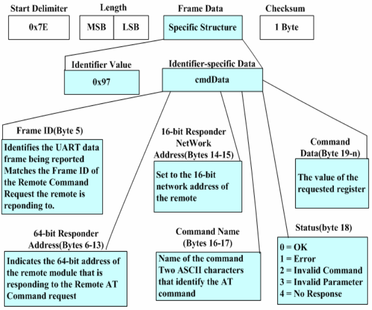
Start Delimiter: 0x7E
Length: Excluding the start delimiter, itself and parity
Frame type: 0x97
Frame ID: This ID is the serial number for the request frame of remote AT command, it can
indentify the response for which request.
64-bit Source Address: The 64-bit MAC address for source address
16-bit Destination Address: The 16-bit network address for source address
AT Command: Currently, all AT commands are only 2 characters, for example ‘DL’, ‘ID’ etc.
It is the ASCII value of the AT command letter.
Parameter Value: If the AT command is check command, it goes with parameter. If it is set
command, it goes without parameter.
Checksum: Excluding 0x7E and length, add all bytes of Frame Data, keep only the lowest 8
bits of the result and subtract from 0xFF, then you will get the checksum.

IV. AT Command
1 Address Command
AT Command Command Description Parameter Range Default Value
MY Read the 16-bit network address of module,
‘0xFFFE’ means the module has not
entered the network.
0-0xFFFE
(Read Only)
0xFFFE
MP Read the 16-bit network address of father
node, ‘0xFFFE’ means this node doesn’t
have father node.
0-0xFFFE
(Read Only)
0xFFFE
NH Feedback the next Router node address that
the current node shoud pass to the specified
node. The parameter is an effective 16-bit
destination address.
0-0xFFFF
SH Read the high 32-bit of the 64-bit MAC
address
0-0xFFFFFFFF
(Read Only)
Fixed value
SL Read the low 32-bit of the 64-bit MAC
address
0-0xFFFFFFFF
(Read Only)
Fixed value
NI Node indentifier, it is a character string, it
should be printable ASCII character. The max
length should not more than 20 characters.
no more than 20
characters
0x20
2 Network Command
AT Command Command Description Parameter Range Default Value
CH Read the working channel. Using the channel
No. defined by 802.15.4. ‘0’ means the
module has not enter the network.
0,0x0B-0x19。
(Read Only)

CE Set the module type, set the device as
Coordinator or Router (Note: EndDevice can
not be set).
0 - Coordinator
1 - Router
1
ID PAN ID, it is 16 bits. If it is ‘0xFFFF’, the
Coordinator will select a ID randomly,
Router and EndDevice will enter the network
with any PAN ID that can be entered.
0-0xFFFF 29AC
PI The gained 16-bit PAN ID, this value is the
module PAN ID distributed in the
network.
0-0xFFFF
(Read Only)
NT Node inquiry time, when execute the ND
command, the NT value will be broadcasted
together. After other nodes receive the
broadcating data, they will delay in a random
time (< NT) and send the response to avoid
network congestion.
0x20-0xFF
(×100ms)
0x3C
NO Network search option, when execute the
NDcommand, whether display the local
node info or not.
0 – Not display
1 - Display
1
RL Inquiry the Router info
Parameter format:
1. No parameter, inquiry all the Router
info saved in the local node.
2. ATRL srcAddr-dstAddr
Inquiry the routing way for sending
message from srcAddr to dstAddr
NL Inquiry the neighbour’s table, return the
neighbour node info of the current node
No parameter
SC Set the working channel. When Coordinator 1-0xFFFF 0x0001

builds the network or Router (EndDevice)
enthers the network, they only search these
channels.
This value uses the bit definition for
selection, i.e. if one bit is ‘1’, and the
corresponding channel is chosen.
0(0x0B) 1(0x0C) 2(0x0D)
3(0x0E) 4(0x0F) 5(0x10)
6(0x11) 7(0x12) 8(0x13)
9(0x14) 10(0x15) 11(0x16)
12(0x17) 13(0x18) 14(0x19)
15(0x1A)
3 RF Parameter Command
AT Command Command Description Parameter Range Default Value
PL Transmitting Power Level 0=12 dBm
1=14 dBm
2=16 dBm
3=18dBm
4=20 dBm
4
4 Serial Port Parameter Command
AT Command Command Description Parameter Range Default Value
AP API enable, set whether use API mode
or not.
0 – API disable
1-API enable
0
BD UART port baud rate setting
0-1200bps
1-2400
5

2-4800
3-9600
4-19200
5-38400
6-57600
7-115200
NB Parity bit setting of UART port 0 – no parity
1 – even parity
2 – odd parity
0
5 I/O Parameter Command
AT Command Command Description Parameter Range
PT Collect/set the DIO2 (6th pin) state None – Digital input
0 - Digital output, low level
1 - Digital output, high level
S1 Collect voltage value, 20th pin
S2 Collect voltage value, 19th pin
S3 Collect voltage value, 18th pin
S4 Collect voltage value, 17th pin
6 Diagnostics Parameter Command
AT Command Command Description Parameter Range
VR/SV Firmware version Read Only
VL Read the detailed version info
of module
ASCII character string.
Only can be read by local AT
command.
Read Only

HV Read the hardware version Read Only
FV Read the protocol stack version Read Only
AI Read the network state 0 – in the network
1 – not in the network
Read Only
7 AT Command Parameter
AT Command Command Description Parameter Range Default Value
CN Exit AT command mode. When execute
this command, the module will exit AT
command mode immediately.
--- ---
8 Sleep Command
AT Command Command Description Parameter Range Default Value
SN The times for EndDevice scans the
network. The default state: doesn’t scan
the network and stay in the sleep state all
the time.
0-9 0
SS The sleep period before EndDevice
enters the network. Before entering the
newtork, if EndDevice still doesn’t enter
the network after scan ‘SN’ times
network, it will enter the sleep state. ‘SS’
is used to define the time for sleep.
0x01-0xFFFF
(× 1ms)
0xFFFE
SM Sleep mode, this value for Coordinator
and Router should be ‘0’, EndDevice
is ‘1’.
0 – Disable Sleep
1- Periodic sleep, but
it can be waken up

forcibly through
pin.
SP Sleep period, it defined the sleep time for
of EndDevice. For the father node, this
value defines how long does it save the
information for its child node.
0x01-0xFFFF
(× 10ms)
0x012C
ST After receiving the data, EndDevice will
enter into sleep after ‘ST’ time.
After receiving the air data, EndDevice
will start a timer, if there is no data
within ‘ST’ time, it will enter into
sleep.
1-0xFFFE
(× 1ms)
0x32
(5s)
9 Execute Command
AT Command Command Description Parameter Range Default Value
WR Save the parameter value into Flash
to keep the value even after power
off.
--- ---
RE Restore to default value --- ---
FR Firmware restart. After receive this
command, the module will execute
firmware restart after 2s.
--- ---
RN Network reset 0- Don’t reset
1- Reset without any cases
2- If the network layer
parameters have been
changed, reset the
network. Otherwise do
0

not reset the network.
ND Search all nodes in the network.
After execute this command, the
module will broadcast the data frame
for finding network node and output
the responses of all nodes from
UART port.
--- ---
V. LBee Zigbee Network
The Physical layer and MAC layer of Zigbee are based on the IEEE802.15.4. The Zigbee
Alliance defines the Network Layer and Application layer based on the IEEE802.15.4. LBee
module can be compatible with all these layers completely. In the LBee Zigbee network, there are
three kinds of modules, i.e. Coordinator, Router and EndDevice. Please refer to the following info
about these module types.
1 Coordinator
The Coordinator is responsible for choosing a channel and a PAN ID to build the network.
And it is the only device to build the network, so every network should have a Coordinator. After
the Coordinator builds the network, it allows new devices for entering network, route data package
and communication with other device types.
The Coordinator selects the channel by scanning different channels. When Coordinator scans
one channel and finds that channel level is larger than a certain value, it will consider as that this
channel has been occupied by other networks, give up this channel and continue to scan until it
finds the unoccupied channel. Users can use SC command to set the Coordinator work on a
definite channel.
After the Coordinator finishes channel and network scanning, it will select a usable channel
and PAN ID to build the network. Users can use ATMY command to check whether the network is
built or not. When the command response is ‘0x0000’, it means the network is already built. Users
also can use ID command to appoint 16-bit PAN ID for Coordinator.
2 Router
Before entering the network, the Router needs to find and enter the network. After entering
the network, Router can help other modules to enter the network, route data package and
communication with other nodes.
The Router finds the network by using network scanning, it is almost same as the way of
Coordinator. When Router sends out a beacon request frame on a definite channel, the
Coordinators or Routers in the nearby network will reply a beacon response. The beacon response
includes the network PAN ID and the info whether it allows other modules for entering. Router
selects a suitable network for entering. The selection condition is that the PAN ID is same as ID
command (when ID = 0xFFFF, it doesn’t need to meet this condition), and the network should
allow other modules for entering. If this channel can not meet these conditions, it will select next
channel for network scanning.
Users can set the SC command value to make that the Router only scans on some channels.
Users also can set ID value to appoint the Router only enters the network with appointed PAN ID.
After Router enters the network, it will get a 16-bit network address for network communication,
which can be read by MY command.
3 EndDevice
Same as Router, before entering the network, EndDevice needs to find and enter the network.
After it enters the network, it can communicate with other nodes. Because it is powered by
battery, it has strict limits for power consumption, so it can not route data package and allow
other nodes for entering.
The networking scanning of EndDevice is similar to Router. The standards for judging
whether a node is allowed for entering are shown as follow:
(1)If its ID command is not ‘0’, and the PAN ID should be same as the ID value.
(2)Whether this node allows other nodes for entering or not.
(3)Whether this node can contain the child node or not.
After EndDevice enters the network, it will get a 16-bit network address for network
communication from its father node, which can be read by MY command. Users can use AI
command to check whether the EndDevice enters the network successfully or not. If the return
value for AI command is ‘0’, it means that the EndDevice enters the network successfully.
Note: Because EndDevice has strict limits for power consumption, so the default setting is
‘Do not scan network’. Users can use SN command to set the times for network scanning.
3.1 The Relationship between Father node and Child node
The power saving of EndDevice is achieved by the periodical sleep. When there are some
coming data packages, the EndDevice is still in sleep state, its father node who help it enter the
network will save the data packages until it wakes up and forward to it after waking up. This is
the relationship between father node and child node.
3.2 Child Node Capability
Router and Coordinator have a child node table, it is used to maintain its child nodes. The
size of the table determines its ability to accommodate child nodes. If there is still space for child
nodes, Router (or Coordinator) will allow other child nodes for entering.
EndDevice
The working principle and operation of EndDevice is the most complicated. It is described
separately here.
When EndDevice enters the network, the node who help it to enter the network is called its
father node.
For power saving purpose, EndDevice sleeps periodically. During the sleep period, it can not
receive data, its father node helps to save the coming data, wait and send to it after waken up.
About the working process for child node and father node, please refer to the following points for
more info.
4 Working Process for Child Node
EndDevice sleeps periodically. When EndDevice wakes up, it will send the request frame to
its father node. After the father node receives the request, it will check whether it has saved the
data for the child node or not, then it will reply a response frame to tell the child node whether it
has data. If the child node receives the father node’s response and finds that there is no data, it will
enter into sleep state. When waking up again, it will send the request frame again to its father node.
The sleep period can be set by SP command.
If the child node receives the father node’s response and finds that there is data, it will
prepare to receive data and will not enter sleep state. After receiving every data package, it will
start a Timer and ask its father node whether there is data for it timely until the Timer is overtime,
i.e. reach the time set by ST command, it will enter sleep.
If EndDevice wants to send data to other nodes in the network, it only could send the data to
its father node first, then execute routing query and finding destination address etc, after that send
out the data, report the sending state to it finally.
When EndDevice is in the sleep state, users can use 9th pin to force it wake up.
5 Working Process for Father Node
If father node receives the data from child node, it will help to save the data, wait the child
node wake up, then send a request frame to child node, after that send the data to child node.
If the child node doesn’t request data from father node within the required time, father node
will delete the data. The required time is called SP, it can be set by SP command. Usually, every
node’s SP value in the same network should be the same.
Annex
This device complies with part 15 of the FCC Rules. Operation is subject to the following
two conditions: (1) This device may not cause harmful interference, and (2) this device
must accept any interference received, including interference that may cause undesired
operation.
Changes or modifications not expressly approved by the party responsible for compliance
could void the user's authority to operate the equipment.
FCC Radiation Exposure Statement
The modular can be installed or integrated in mobile or fix devices only. This modular
cannot be installed in any portable device, for example, USB dongle like transmitters is
forbidden.
This modular complies with FCC RF radiation exposure limits set forth for an
uncontrolled environment. This transmitter must not be co-located or operating in
conjunction with any other antenna or transmitter. This modular must be installed and
operated with a minimum distance of 20 cm between the radiator and user body.
If the FCC identification number is not visible when the module is installed inside another
device, then the outside of the device into which the module is installed must also display
a label referring to the enclosed module. This exterior label can use wording such as the
following: “Contains Transmitter Module FCC ID: WMUHAC-LBEE
When the module is installed inside another device, the user manual of this device must
contain below warning statements;
1. This device complies with Part 15 of the FCC Rules. Operation is subject to the
following two conditions:
(1) This device may not cause harmful interference.
(2) This device must accept any interference received, including interference that may
cause undesired operation.
2. Changes or modifications not expressly approved by the party responsible for
compliance could void the user's authority to operate the equipment.