HAC Telecom Technology HAC-UBEEV3X Zigbee Module User Manual HAC UBee Specification V3 X
Shenzhen HAC Telecom Technology Co. Ltd. Zigbee Module HAC UBee Specification V3 X
User Manual
HAC-UBee
2.4G Low Power Data Radio Module
(Based on ZigBee protocol)
V3.X
SHENZHEN HAC TELECOM TECHNOLOGY CO., LTD
Address : 3rd Area, 19th Fl, Tower A, HaiSong Building, Tai Ran 9th Rd,
Futian, ShenZhen, China.
Tel : +86-755-23981078 23981077
Fax : +86-755-23981007
E-mail : webmaster@rf-module-china.com
Website : http://www.rf-module-china.com

HAC-Ubee manual V3.X SHENZHEN HAC TECHNOLOGY CO., LTD.
FAX:+86-755-23981007 E-MAIL:webmaster@rf-module-china.com www.rf-module-china.com - 2
-
Catalogue
I. Features of HAC-Ubee Wireless Module ..................................................................................3
II. Applications of HAC-Ubee Wireless Module ..........................................................................4
III. Using Methods of HAC-Ubee Wireless Module .......................................................................4
IV. Development Kit for HAC-Ubee Wireless Module...................................................................8
V. Working Mode of HAC-Ubee Wireless Module.......................................................................13
VI. Assistant Software .....................................................................................................................34
VII. Appendix ..................................................................................................................................35

HAC-Ubee manual V3.X SHENZHEN HAC TECHNOLOGY CO., LTD.
FAX:+86-755-23981007 E-MAIL:webmaster@rf-module-china.com www.rf-module-china.com - 3
-
I Features of HAC-Ubee Wireless Module
HAC-Ubee is a kind of low power wireless module based on Zigbee protocol stack. The features
are shown as follow:
1. Low power transmission with 2.5mW(4dBm), and receiving sensitivity is -105dBm
(BER=10-2).
2. ISM frequency band with no require of applying frequency. The carrier frequency is 2.4GHz.
3. High anti-interference and Low BER (Bit error Rate)
Based on the Quadrature Phase Shift Keying (QPSK) modulation, the high-efficiency forward
error correction channel encoding technology is used to enhance data’s resistance to both
transient interference and random interference. Narrowband interference of the same frequency
can be suppressed by Direct Sequence Spread Spectrum. The 16 CRC verify bits can be used to
check mistake.
4. The transmitting speed in the air can reach up to 250kbps.
5. Transmission Distance
Within the visible range, the reliable transmission distance is 300m.
6. Multi-channels
HAC-Ubee offers 16 channels. It will select the suitable and reliable communication channel
automatically according to the user’s environment.
7. UART interface
HAC-Ubee provides a UART interface of TTL level. The default interface baud rate is 38400bps
ex-factory , and the parity is no-parity (8N1).
8. Low power consumption
The receiving current is less than or equal to 27mA, and the transmitting current is less than or
equal to 40mA.
9. Small size and light weight
10. By using SoC , the transceivers have less peripheral circuits, higher reliability,and lower failure
rate.
11. Offering many kinds of antenna connecting methods, such as PCB antenna, Chip antenna, IPX
antenna connecting base and so on.
12. It can meet for the protocol of IEEE 802.15.4 for 2.4GHz and the application of ZigBee, it can
make network automatically.
13. This device complies with part 15 of the FCC rules. Operation is subject to the following two

HAC-Ubee manual V3.X SHENZHEN HAC TECHNOLOGY CO., LTD.
FAX:+86-755-23981007 E-MAIL:webmaster@rf-module-china.com www.rf-module-china.com - 4
-
conditions:
(1) This device may not cause harmful interference, and
(2) This device must accept any interference received, including interference that may cause
undesired operation.
Changes or modifications not expressly approved by the party responsible for compliance could
void the user’s authority to operate the equipment.
RF Exposure warning statement:
The device has been evaluated to meet general RF exposure requirement. The device can be
used in portable exposure condition without restriction.
II. Applications of HAC-Ubee Wireless Module
HAC-Ubee low power wireless module is suitable for:
﹡Home appliances intelligent control.
﹡Auto Meter Reading system.
﹡Industry telemetry and automatic data collection system.
﹡Security and alarm.
﹡Wireless monitor for hotel and equipment of computer room, door’s security, personnel
orientation.
﹡Traffic and the control for street lamp.
﹡Logistics, active RFID, POS system and wireless handheld terminal.
III. Using Methods of HAC-Ubee Wireless Module
3.1 Technical Parameter of HAC-Ubee
Parameter Name
Minimum Typical Value Maximum
Unit
Electric Performance (25℃)
Power Supply 3.0 3.3 3.6 V
Interface Level -0.3 VCC + 0.3≤3.6 V
Transmitting Current 36 38 40 mA
Receiving Current 25 26 27 mA
Sleeping Current 3 μA
Wireless Performance(25℃)
HAC-Ubee manual V3.X SHENZHEN HAC TECHNOLOGY CO., LTD.
FAX:+86-755-23981007 E-MAIL:webmaster@rf-module-china.com www.rf-module-china.com - 5
-
Working Frequency 2.405 2.480 GHz
Transmitting Power 3.8 4.0 4..2 dBm
Receiving Sensitivity -97 dBm
Transmitting Rate 250 Kbps
General Performance
Interface baud rate 2400 38400 115200 bps
Working Temperature -40 80 ℃
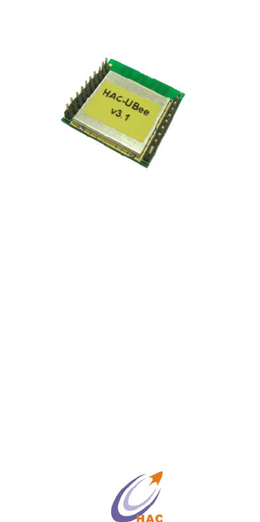
Size 25.5 X 24.4 X 4 mm
Table 1 Technical Parameter of HAC-Ubee
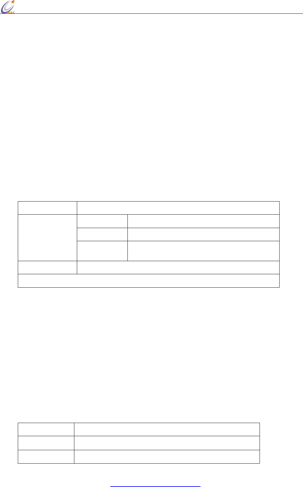
3.2 The Size of HAC-Ubee
Picture 1 The Size of HAC-Ubee
3.3 Pin Definition of HAC-Ubee
Pin Definition Input/Output Function Instruction
1 VCC IN Power Supply, +3.0~3.6V
2 TXD OUT Output serial data
3 RXD IN Input serial data
HAC-Ubee manual V3.X SHENZHEN HAC TECHNOLOGY CO., LTD.
FAX:+86-755-23981007 E-MAIL:webmaster@rf-module-china.com www.rf-module-china.com - 6
-
4 DIO1 IN/OUT Data I/O1
5 RESET IN Low level reset
6 DIO2 IN/OUT Data I/O2
7 DIO3 IN/OUT Data I/O3
8 DIO4/DD IN/OUT Data I/O4 / Program data
9 DIO5/DC IN/OUT Data I/O5 / Program clock
10 GND Power supply (Negative),Ground
11 DIO6 IN/OUT Data I/O6
12 DIO7 IN/OUT Data I/O7
13 DIO8 IN/OUT Data I/O8
14 DIO9 IN/OUT Data I/O9
15 DIO10 IN/OUT Data I/O10
16 DIO11 IN/OUT Data I/O11
17 DIO12/ADC3 IN/OUT Data I/O12/Analog Input 3
18 DIO13/ADC2 IN/OUT Data I/O13/Analog Input 2
19 DIO14/ADC1 IN/OUT Data I/O14/Analog Input 1
20 DIO15/ADC0 IN/OUT Data I/O15/Analog Input 0
Table 2 Pin Definition of HAC-Ubee
3.1 HAC-Ubee Optional fittings
1)Standard fittings
Standard Ubee V3.0 always goes with PCB antenna, excluding IPX antenna base.
2)There is an optional Chip antenna called HAC-Antenna-CH2400 for customers。
When using Chip antenna, it needs to cut down the PCB antenna connection and connect
with pad of Chip antenna. In such fittings, it doesn’t include antenna base.
HAC-Ubee manual V3.X SHENZHEN HAC TECHNOLOGY CO., LTD.
FAX:+86-755-23981007 E-MAIL:webmaster@rf-module-china.com www.rf-module-china.com - 7
-
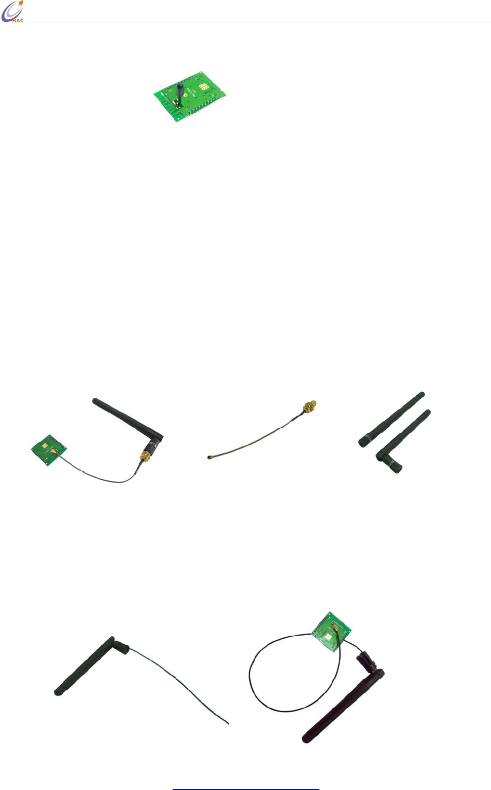
3)Using antenna cable to connect with external antenna
Such a connecting method is suitable for the products with the enclosure that has strong
shield for wireless signal. The module has been soldered with IPX antenna base, at the same
time, it needs to cut down the PCB antenna and lead the signal to IPX antenna base. If the IPX
antenna base isn’t needed, it can solder antenna cable directly. In this way, the connecting
method is much firmer, but it is not suitable for transportation and assembly, because the pad
for soldering antenna cable is easy to fall off if there is a force during the process of
transportation and assembly.
A Using antenna cable with two ends connector called KX-IPEX-10G1-SMA-F to connect
with an 10cm external folding helical antenna called HAC-Antenna-LX2400-10-ZSMA-M。
HAC-KX-IPEX-10G1-SMA-F HAC-Antenna-LX2400-10-ZSMA-M
B Using antenna called LX2400Z-10-KX-10G1-IPEX to connect with the HAC-Ubee module
directly.
HAC-Ubee manual V3.X SHENZHEN HAC TECHNOLOGY CO., LTD.
FAX:+86-755-23981007 E-MAIL:webmaster@rf-module-china.com www.rf-module-china.com - 8
-
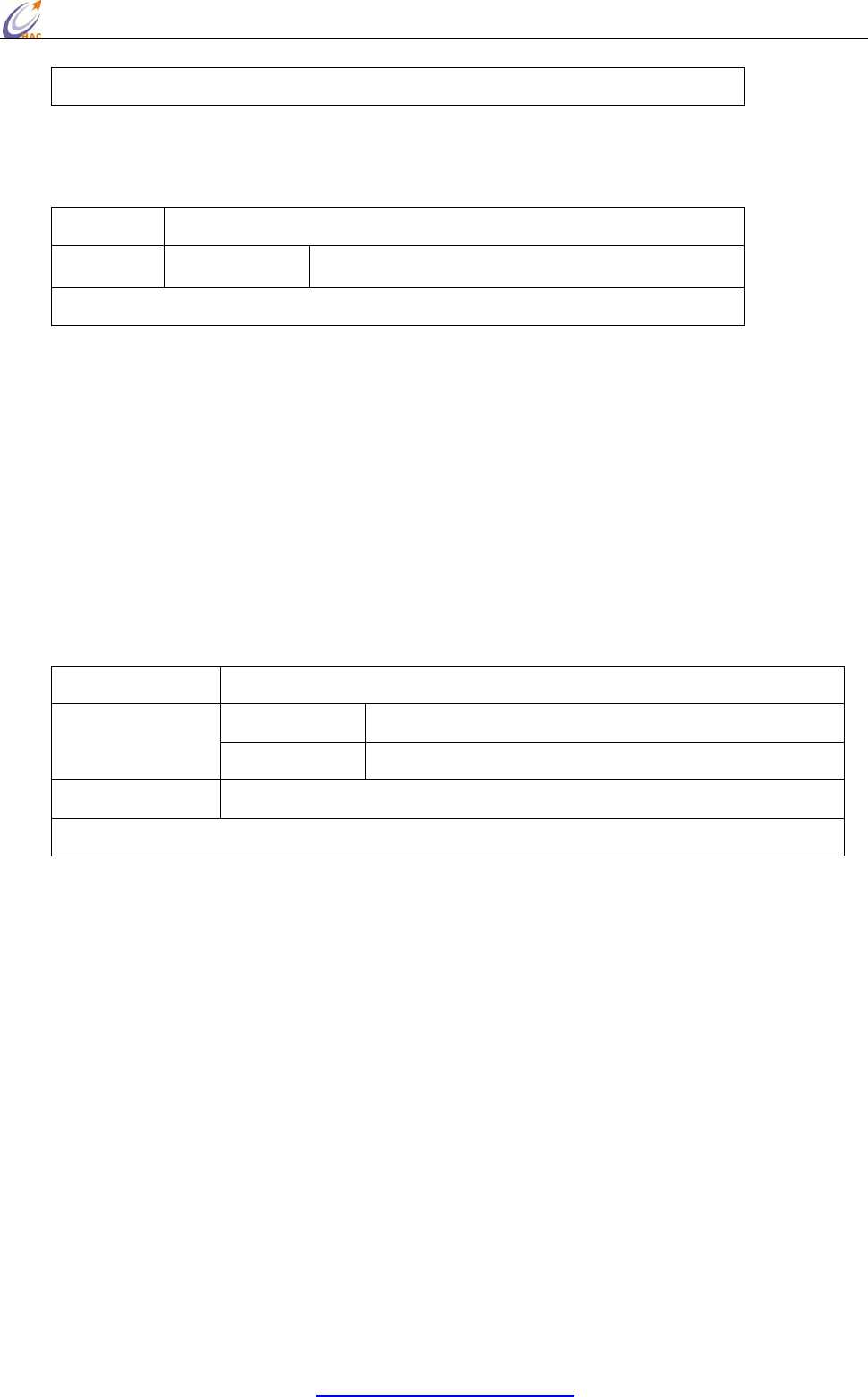
IV. Development Kit for HAC-Ubee Wireless Module
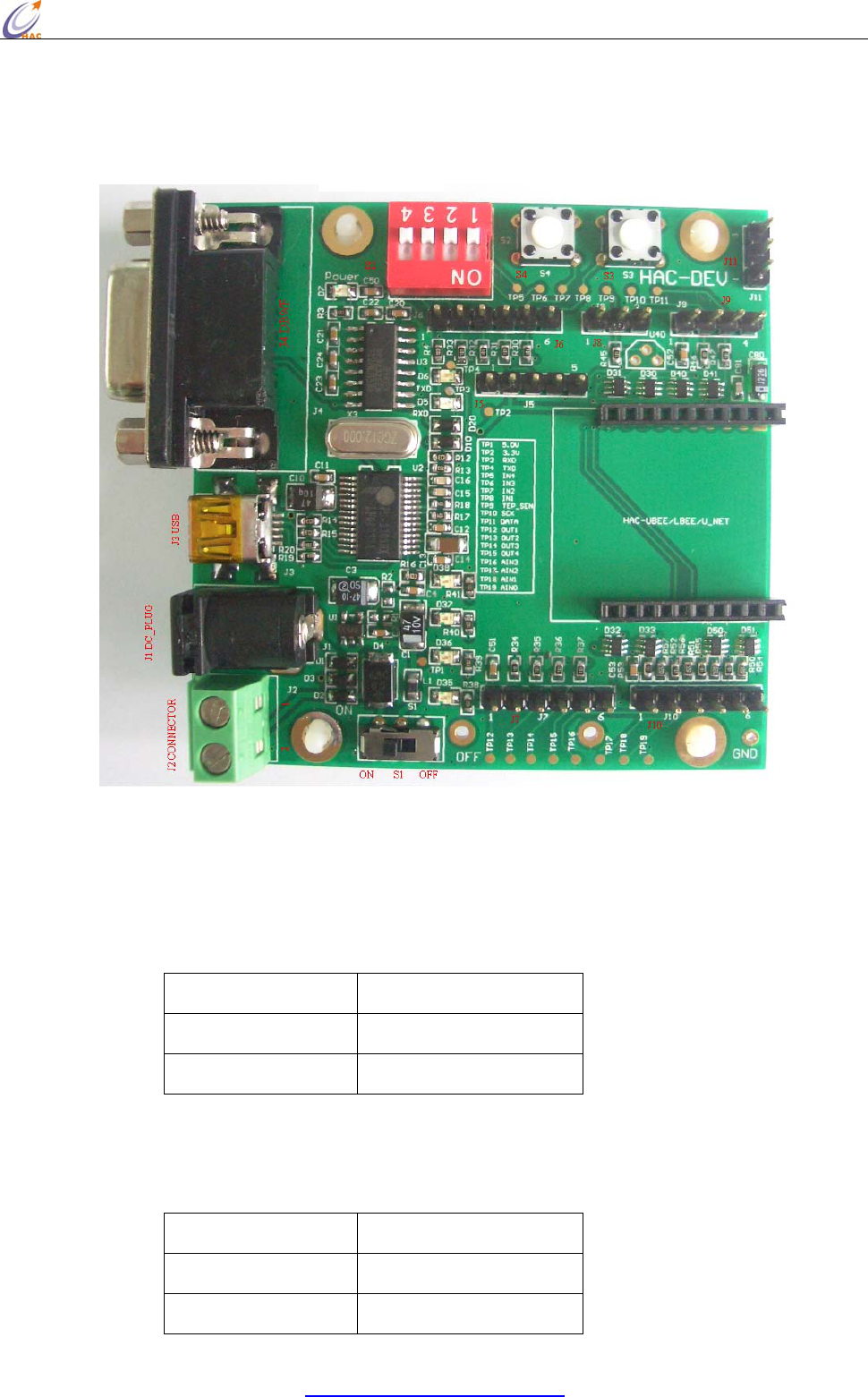
4.1 General Information for HAC-DEV Development Kit
Picture 2 HAC-DEV
Connector Definition:
a. J1 (DC_PLUG ) 5V power supply input
b. J2 (DC_CONNECTOR) 5V power supply input
Pin Name Definition
Pin1 GND
Pin2 5V
c. J3 (USB_ PLUG) USB port, USB to Serial port. Please refer to the Appendix 2 for the
installation for USB Driver.
d. J4 (DB9/F) RS232 data port
Pin Name Definition
Pin2 TXD
Pin3 RXD

HAC-Ubee manual V3.X SHENZHEN HAC TECHNOLOGY CO., LTD.
FAX:+86-755-23981007 E-MAIL:webmaster@rf-module-china.com www.rf-module-china.com - 9
-
Pin5 GND
Other pins No Definition
e. J5 (Programming) CC2530F256 Program Port
Pin Name Definition
Pin1 GND
Pin2 3.3V Input
Pin3 DD
Pin4 DC
Pin5 RESET
If there is a external power supply, don’t connect the Pin2: 3.3V.
f. J6 (DA_IN) Digital Level Input
Pin Name Definition
Pin1 3.3V input
Pin2 IN4 Digital Input 4th way
Pin3 IN3 Digital Input 3rd way
Pin4 IN2 Digital Input 2nd way
Pin5 IN1 Digital Input 1st way
Pin6 GND
g. J7 (DA_OUT) Digital Level Output
Pin Name Definition
Pin1 3.3V Output
Pin2 OUT1 Digital Output 1st way
Pin3 OUT2 Digital Output 2nd way
Pin4 OUT3 Digital Output 3rd way
Pin5 OUT4 Digital Output 4th way
Pin6 GND
h. J8 (DS18B20) Temperature Sensor DS18B20 port
Pin Name Definition
Pin1 GND
Pin2 TEP_SEN
Pin3 GND
i. J9 (SENSOR) I2C port, connect with sensor
HAC-Ubee manual V3.X SHENZHEN HAC TECHNOLOGY CO., LTD.
FAX:+86-755-23981007 E-MAIL:webmaster@rf-module-china.com www.rf-module-china.com -
10 -
Pin Name Definition
Pin1 3.3V
Pin2 SCK
Pin3 DATA
Pin4 GND
j. J10(Analog Signals IN)4~20mA current signal input
Pin Name Definition
Pin1 3.3V Output
Pin2 AIN3 Current Signal Input 3rd way
Pin3 AIN2 Current Signal Input 2nd way
Pin4 AIN1 Current Signal Input 1st way
Pin5 AIN0 Current Signal Input 0 way
Pin6 GND
k. J11 (UART_TTL) Serial Port for TTL Level
Pin Name Definition
Pin1 TXD
Pin2 RXD
Pin3 GND
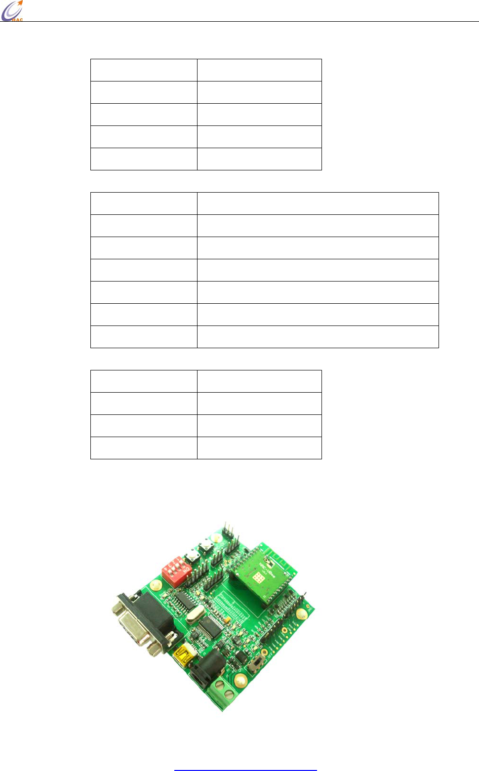
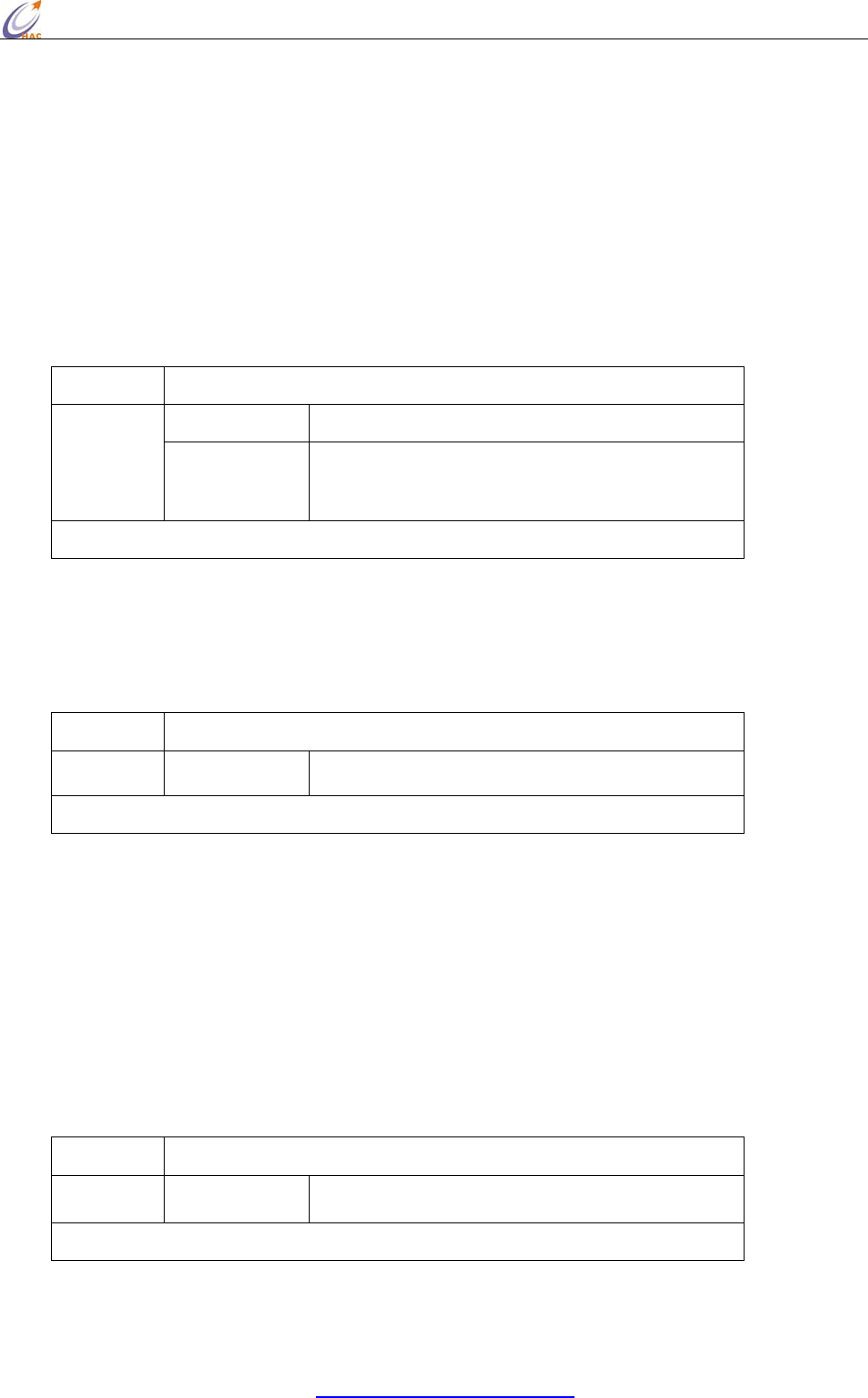
4.2 Connecting Methods between HAC-Ubee and HAC-DEV

HAC-Ubee manual V3.X SHENZHEN HAC TECHNOLOGY CO., LTD.
FAX:+86-755-23981007 E-MAIL:webmaster@rf-module-china.com www.rf-module-china.com -
11 -
Picture 3 Connecting Methods between HAC-Ubee and HAC-DEV
4.3 Schematic Diagram for HAC-DEV
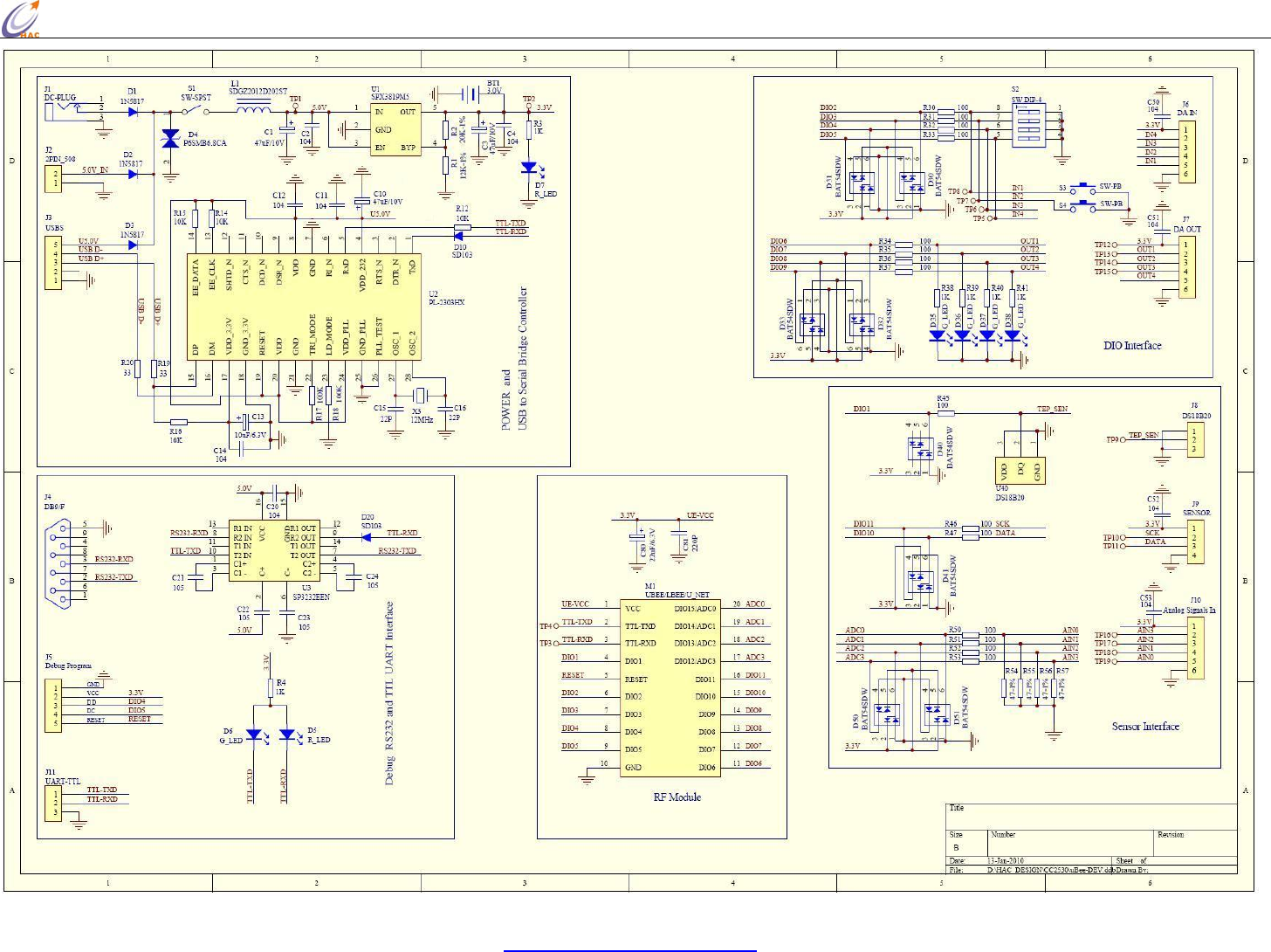
HAC-Ubee manual V3.X SHENZHEN HAC TECHNOLOGY CO., LTD.
FAX:+86-755-23981007 E-MAIL:webmaster@rf-module-china.com www.rf-module-china.com - 12 -

HAC-Ubee manual V3.X SHENZHEN HAC TECHNOLOGY CO., LTD.
FAX:+86-755-23981007 E-MAIL:webmaster@rf-module-china.com www.rf-module-china.com -
13 -
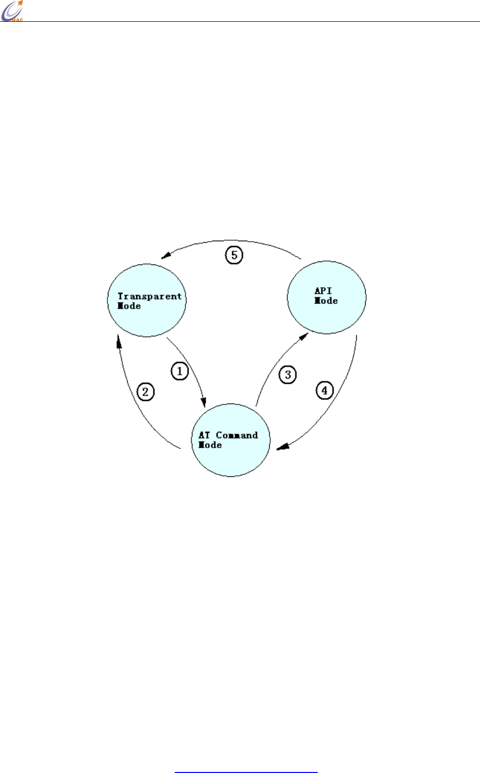
V. Working Mode of HAC-Ubee Wireless Module
5.1. Working Mode of HAC-Ubee Wireless Module
There are three working modes for HAC-Ubee. They are: Transparent Mode, API Mode, AT
Command Mode.
5.1.1 Transparent Mode
By default, Modules operate in Transparent Mode. When operating in this mode, the modules act as
a serial line replacement - all UART data received through the RXD pin is queued up for RF
transmission. When RF data is received, the data is sent out the TXD pin.
z No serial characters are received for the amount of time determined.
z The maximum number of characters that will fit in an RF packet (85) is received.
Serial-to-RF Packetization
Data is buffered in the RXD buffer until one of the following causes the data to be packetized and
transmitted: If the module cannot immediately transmit (for instance, if it is already receiving RF
data), the serial data is stored in the RXD Buffer. The data is packetized and sent at timeout or when
85 bytes (maximum packet size) are received.
5.1.2 API Mode
API (Application Programming Interface) Operation is an alternative to the default Transparent
Operation. The frame-based API extends the level to which a host application can interact with the
networking capabilities of the module.
When in API mode, all data entering and leaving the module is contained in frames that define
operations or events within the module.
Transmit Data Frames (received through the RXD pin (pin 3)) include:
• RF Transmit Data Frame
• Command Frame (equivalent to AT commands)
Receive Data Frames (sent out the TXD pin (pin 2)) include:
• RF-received data frame
• Command response
• Event notifications such as reset, associate, disassociate, etc.
The API provides alternative means of configuring modules and routing data at the host application
layer. A host application can send data frames to the module that contain address and payload
information instead of using command mode to modify addresses. The module will send data
frames to the application containing status packets; as well as source, RSSI and payload information
from received data packets. The API operation option facilitates many operations such as the
examples cited below:
HAC-Ubee manual V3.X SHENZHEN HAC TECHNOLOGY CO., LTD.
FAX:+86-755-23981007 E-MAIL:webmaster@rf-module-china.com www.rf-module-china.com -
14 -
• Transmitting data to multiple destinations without entering Command Mode
• Receive success/failure status of each transmitted RF packet
• Identify the source address of each received packet
* How to let the module work under the API mode after power up?
User can use AT command to enter the API mode. The setup steps are shown as follow:
Enter the AT Command page
Input the 3-character command sequence “+++” and wait for the reply “OK” from module.
Input “ATAP 1<CR>” command, the module will reply “OK”. It is used to set the module working
under API mode.
Input “ATWR<CR>” command, the module will reply “OK”. It is used to save the setting. So the
module will enter API mode automatically when restart the module next time.
Input “ATCN<CR>” command to exit from the AT Command mode. Now, the module works under
the API mode. Even power up the module again, it still enters the API mode directly.
5.1.3 AT Command Mode
To modify or read RF Module parameters, the module must first enter into Command Mode - a state
in which incoming characters are interpreted as commands. Two Command Mode options are
supported: AT Command Mode [refer to section below] and API Command Mode
Send the 3-character command sequence “+++” and observe guard times before and after the
command characters.
NOTE: Failure to enter AT Command Mode is most commonly due to baud rate mismatch. Ensure
the ‘Baud’ setting on the “PC Settings” tab matches the interface data rate of the RF module. By
default, the BD parameter = 5 (38400 bps).
To read a parameter value stored in the RF module’s register, omit the parameter field.
The preceding example would change the RF module Channel to “0x0B”. To store the new value to
non-volatile (long term) memory, subsequently send the WR (Write) command.
For modified parameter values to persist in the module’s registry after a reset, changes must be
saved to non-volatile memory using the WR (Write) Command. Otherwise, parameters are restored
to previously saved values after the module is reset.
System Response: When a command is sent to the module, the module will parse and execute the
HAC-Ubee manual V3.X SHENZHEN HAC TECHNOLOGY CO., LTD.
FAX:+86-755-23981007 E-MAIL:webmaster@rf-module-china.com www.rf-module-china.com -
15 -
command. Upon successful execution of a command, the module returns an “OK” message. If
execution of a command results in an error, the module returns an “ERROR” message.
NOTE: Some parameters will validate at once after setting, but some parameters will validate after
restart the module. So please read every AT command very carefully.
To Exit AT Command Mode:
Send the ATCN (Exit Command Mode) command (followed by a carriage return). [OR]
If no valid AT Commands are received within 10 seconds.
5.1.4 How to select the working mode
The default setting in the factory is transparent working mode.
1. Under the transparent mode, input 3-character command sequence “+++” from serial port, it will
change for the AT Command mode.
2. When you select the transparent working mode (ATAP 0), inputting “ATCN” command can exit
from the AT Command mode and enter the transparent mode. Or when you select the transparent
working mode (ATAP 0), if there is no input in 10 seconds, the module will exit from the AT
Command mode and enter the transparent mode.
3. When you select the API working mode (ATAP 1), inputting “ATCN” command can exit from the
AT Command mode and enter the API mode. Or when you select the API working mode (ATAP 1),
if there is no input in 10 seconds, the module will exit from the AT Command mode and enter the
API mode.
4. Under the API mode, input 3-character command sequence “+++” will let the module switch to
AT Command mode.
5. Under API mode, when using AT Command to setup transparent mode (ATAP 0), the module will

HAC-Ubee manual V3.X SHENZHEN HAC TECHNOLOGY CO., LTD.
FAX:+86-755-23981007 E-MAIL:webmaster@rf-module-china.com www.rf-module-china.com -
16 -
switch to transparent mode.
5.2 AT Command
AT
Command Command
Category Name and Description Parameter Range Default Firmware
Version
WR Special Write. Write all configurable parameter
values to non-volatile memory so that
parameter modifications persist through
subsequent power-up or reset.
- - >=0x19
RE Special Restore Defaults. Restore module
parameters to factory defaults. - - >=0x19
FR Special Software Reset. Immediately performs a
hard reset. - - >=0x19
MT Networking Module Mode. Read the device type of
module. 0-2
0-Coordinator
1-Router
2-EndDevice
- >=0x19
CH Networking Channel. Set/Read the channel number used
for transmitting and receiving data between
RF modules (uses 802.15.4 protocol channel
numbers).
0x0B - 0x1A 0x0B >=0x19
ID Networking PAN ID. Set/Read the setup PAN (Personal
Area Network) ID. 0 - 0xFFFF 0x19AC >=0x19
PI Networking PAN ID. Read the PANID in the network. 0 - FFFF
(Read only) - >=0x19
DH Networking 64-bit Destination Address High. Set/Read
the upper 32 bits of the 64-bit destination
address. When combined with DL, it defines
the destination address used for
transmission. 0x000000000000FFFF is the
broadcast address for the PAN.
0 - 0xFFFFFFFF 0x00 >=0x19
DL Networking 64-bit Destination Address Low. Set/Read
the lower 32 bits of the 64-bit destination
address. When combined with DH, DL
defines the destination address used for
transmission. 0x000000000000FFFF is the
broadcast address for the PAN.
0 - 0xFFFFFFFF 0xFFFF >=0x19
MY Networking 16-bit Source Address. Read the RF module
16-bit source address. 0-0xFFFF
(Read only) - >=0x19
SH Networking Serial Number High. Set/Read high 32 bits
of the RF module's unique IEEE 64-bit
address.
0 - 0xFFFFFFFF - >=0x19
SL Networking Serial Number Low. Set/Read low 32 bits of
the RF module's unique IEEE 64-bit
address.
0 - 0xFFFFFFFF - >=0x19
DS Networking 16-bit Destination Address. Set/Read the
lower 16 bits destination address. 0xFFFF is
the broadcast address for the PAN.
0 - 0xFFFF 0xFFFF >=0x19
DT Networking Destination Address Type. Set/Read the
destination address type. 0-1
0- 64bit
1-16bit
1 >=0x19
RN Networking Reset Network. Reset network, search the
network again after restart the module.
Note: after reset network and search
network again, the 16-bit address may
change.
0-1
0 = Disabled
1 = Enabled
0 >=0x19
AP Serial
Interfacing API Enable. Disable/Enable API Mode. 0 - 1
0 = Disabled
1 = API enabled
0 >=0x19
BD Serial
Interfacing Interface Data Rate. Set/Read the serial
interface data rate for communications
between the RF module serial port and host.
1 = 2400
2 = 4800
3 = 9600
4 = 19200
5 = 38400
5 >=0x19
HAC-Ubee manual V3.X SHENZHEN HAC TECHNOLOGY CO., LTD.
FAX:+86-755-23981007 E-MAIL:webmaster@rf-module-china.com www.rf-module-china.com -
17 -
6 = 57600
7 = 115200
CN AT Command
Mode Options Exit Command Mode. Explicitly exit the
module from AT Command Mode. - - >=0x19
HV Diagnostics Hardware Version. Read hardware version
of the RF module. 0 - 0xFFFF
(Read only) - >=0x19
VR Diagnostics Firmware Version. Read firmware version
of the RF module. 0 - 0xFF
(Read only) - >=0x19
5.2.1 AP
<Serial Interfacing> The AP command is used to enable the RF module to operate using a
frame-based API instead of using the default Transparent (UART) mode.
Comman
d
ATAP (API Enable)
Range 0-1
Default Value 0
Parameter
Va lu e 0: Disabled (Transparent operation)
1: API enabled
Effective Conditions
V
alidate at once after the comman
d
Minimum Firmware Version Require
d
:0x19
The examples for changing the working mode:
Input 3-character command sequence “+++” and switch to the AT Command mode.
Using ATAP command to setup the working mode you want, such as ATAP 0<CR> or ATAP
1<CR>.
If the setting is still needed to be validated after restart the module next time, using ATWR<CR>
command to write the setting into Non-volatile memory.
Input “ATCN<CR> command to exit from AT Command mode, the module will enter the setting
working mode.
5.2.2 BD
<Serial Interfacing> The BD command is used to set and read the serial interface data rate used
between the RF module and host. This parameter determines the rate at which serial data is sent to
the module from the host. To validate the setting parameters,it needs to write the data to
non-volatile memory after modifying interface data rates. And Modified interface data rates do not
take effect until restart the module next time. When parameters 1-7 are sent to the module, the
respective interface data rates are used (as shown in the table on the right). The RF data rate is not
affected by the BD parameter. We recommend that users don’t select too low interface data rate, or
it will cause the serial port data communication overflow.
Comman
d
ATBD (Interface Data Rate)

HAC-Ubee manual V3.X SHENZHEN HAC TECHNOLOGY CO., LTD.
FAX:+86-755-23981007 E-MAIL:webmaster@rf-module-china.com www.rf-module-china.com -
18 -
Range 1-7
Default Value 5
Parameter
Va lu e 1 = 2400
2 = 4800
3 = 9600
4 = 19200
5 = 38400
6 = 57600
7 = 115200
Effective Conditions Use WR command to save setting, it will be effective after restart the module again.
Minimum Firmware Version Require
d
:0x19
The examples for changing the serial port baud rate:
Input 3-character command sequence “+++” and switch to the AT Command mode.
Using ATBD command to setup the serial port baud rate you want, such as ATBD 6<CR>.
Using ATWR command to write the setting into Non-volatile memory
Input “ATFR<CR> command, the module will restart at once.
5.2.3 CH
<Networking {Addressing}> The CH command is used to set/read the operating channel on which
RF connections are made between RF modules. The channel is one of three addressing options
available to the module. The other options are the PAN ID (ID command) and destination addresses
(DL, DH & DS commands). In order for modules to communicate with each other, the modules
must share the same channel number. Different channels can be used to prevent modules in one
network from listening to trans-missions of another. Adjacent channel rejection is 23 dB. The
module uses channel numbers of the 802.15.4 standard. Center Frequency = 2.405 + (CH - 11d) * 5
MHz (d = decimal)
To validate setting parameters, when setting the channel, at the same time, using the RN command
to setup the module as that reset the network after restart next time, then write the settings to the
non-volatile memory. In this way, the module will work on the new channel after restart the
module next time.
Command ATCH (Channel)
Range 0x0B - 0x1A Parameter
Default Value 0x0B
Effective Conditions RN=1, Use WR command to save setting, it will be effective after restart the module again.
Minimum Firmware Version Required:0x19
The examples for changing the channel:
HAC-Ubee manual V3.X SHENZHEN HAC TECHNOLOGY CO., LTD.
FAX:+86-755-23981007 E-MAIL:webmaster@rf-module-china.com www.rf-module-china.com -
19 -
Input 3-character command sequence “+++” and switch to the AT Command mode.
Using ATCH command to setup the channel you want, such as ATCH 0E<CR>.
Using ATRN command to setup the module reset the network after restart the module next time,
ATRN 1<CR>.
Using ATWR command to write the setting into Non-volatile memory
Input “ATFR<CR> command, the module will restart at once.
5.2.4 CN
<AT Command Mode Options> The CN command is used to explicitly exit the RF module from AT
Command Mode.
Command ATCN(Exit Command Mode)
Parameter None
Effective Conditions Validate at once
Minimum Firmware Version Required:0x19
5.2.5 DH
<Networking {Addressing}> The DH command is used to set and read the upper 32 bits of the RF
module's 64-bit destination address. When combined with the DL (Destination Address Low)
parameter, it defines the destination address used for transmission. An module will only
communicate with other modules having the same channel (CH parameter), PAN ID (ID parameter)
and destination address (DH + DL parameters). 0x000000000000FFFF (DL concatenated to DH) is
the broadcast address for the PAN.
Only under the transparent mode, and DT=0, the setting will be effective.
Command ATDH (Destination Address High)
Range 0x00 - 0xFFFFFFFF Parameter
Default Value 0x00
Effective Conditions Validate at once
Minimum Firmware Version Required:0x19
The examples for changing the upper 32-bit of destination address:
Input 3-character command sequence “+++” and switch to the AT Command mode.
Using ATDH command to setup the upper 32-bit of destination address you want, such as ATDH
0<CR>.
Using ATWR command to write the setting into Non-volatile memory
Input “ATCN<CR> command to exit from the AT Command mode.
HAC-Ubee manual V3.X SHENZHEN HAC TECHNOLOGY CO., LTD.
FAX:+86-755-23981007 E-MAIL:webmaster@rf-module-china.com www.rf-module-china.com -
20 -
5.2.6 DL
<Networking {Addressing}> The DL command is used to set and read the lower 32 bits of the RF
module's 64-bit destination address. When combined with the DH (Destination Address High)
parameter, it defines the destination address used for transmission. A module will only communicate
with other mod-ules having the same channel (CH parameter), PAN ID (ID parameter) and
destination address (DH + DL parameters). 0x000000000000FFFF (DL concatenated to DH) is the
broadcast address for the PAN.
Only under the transparent mode, and DT=0, the setting will be effective.
Command ATDL (Destination Address Low)
Range 0x00 - 0xFFFFFFFF Parameter
Default Value 0xFFFF
Effective Conditions Validate at once
Minimum Firmware Version Required:0x19
The examples for changing the lower 32-bit of destination address:
Input 3-character command sequence “+++” and switch to the AT Command mode.
Using ATDL command to setup the lower 32-bit of destination address you want, such as ATDL
FFFF<CR>.
Using ATWR command to write the setting into Non-volatile memory
Input “ATCN<CR> command to exit from the AT Command mode.
5.2.7 DS
<Networking {Addressing}> The DS command is used to set and read the RF module's 16-bit
destination address. A module will only communicate with other modules having the same channel
(CH parameter), PAN ID (ID parameter) and destination address (64bit or 16bit). 0xFFFF is the
broadcast address for the PAN.
Only under the transparent mode, and DT=1, the setting will be effective.
Command ATDS (Short Destination Address/ 16bit Destination Address)
Range 0x00 - 0xFFFF Parameter
Default Value 0xFFFF
Effective Conditions Validate at once
Minimum Firmware Version Required:0x19
The examples for changing the 16-bit of destination address:
HAC-Ubee manual V3.X SHENZHEN HAC TECHNOLOGY CO., LTD.
FAX:+86-755-23981007 E-MAIL:webmaster@rf-module-china.com www.rf-module-china.com -
21 -
Input 3-character command sequence “+++” and switch to the AT Command mode.
Using ATDS command to setup the 16-bit of destination address you want, such as ATDS
FFFF<CR>.
Using ATWR command to write the setting into Non-volatile memory
Input “ATCN<CR> command to exit from the AT Command mode.
5.2.8 DT
<Networking {Addressing}> The DT command is used to set and read the RF module's destination
address type,64-bit or 16-bit. A module will only communicate with other modules having the same
channel (CH parameter), PAN ID (ID parameter) and destination address (64bit or 16bit).
This parameter only validates under the transparent mode. Under the transparent mode, all UART
data received through the RXD pin is queued up for RF transmission,when DT is equal to 0, the
destination address for transmitting is 64-bit address which is the combination of DH and DL.
When DT is equal to 1, the destination address for transmitting is 16-bit address assigned by DS.
Command ATDT(Destination Address Type 64-bit or 16bit)
Range 0-1
Default Value 1
Parameter
Va lu e 0 = 64-bit Destination Address
1 = 16-bit Destination Address
Effective Conditions Validate at once
Minimum Firmware Version Required:0x19
The examples for changing the type of destination address:
Input 3-character command sequence “+++” and switch to the AT Command mode.
Using ATDT command to setup the destination address you want, such as ATDT 1<CR>.
Using ATWR command to write the setting into Non-volatile memory
Input “ATCN<CR> command to exit from the AT Command mode.
5.2.9 FR
<Special> The FR command is used to force a software reset on the RF module. The reset simulates
powering off and then on again the module.
Command ATFR(Software Reset)
Parameter None
Effective Conditions Validate at once
HAC-Ubee manual V3.X SHENZHEN HAC TECHNOLOGY CO., LTD.
FAX:+86-755-23981007 E-MAIL:webmaster@rf-module-china.com www.rf-module-china.com -
22 -
Minimum Firmware Version Required:0x19
5.2.10 HV
<Diagnostics> The HV command is used to read the hardware version of the RF module.
Command ATHV(Hardware Version)
Parameter Range 0-0xFFFF[Read-only]
Minimum Firmware Version Required:0x19
5.2.11 ID
<Networking {Addressing}> The ID command is used to set and read the PAN (Personal Area
Network) ID of the RF module. Only modules with matching PAN IDs can communicate with each
other. Unique PAN IDs enable control of which RF packets are received by a module.
To validate the setting PAN ID, when setting the PAN ID, at the same time, using the RN command
to setup the module as that reset the network after restart next time, then write the settings to the
non-volatile memory. In this way, the PAN ID will be effective after restart the module next time.
Command ATID (PAN ID)
Range 0x00 - 0xFFFF Parameter
Default Value 0x19AC
Effective Conditions RN=1, Use WR command to save setting, it will be effective after restart the module again.
Minimum Firmware Version Required:0x19
The PAN ID of all the modules in a network should be the same. If users want to assign PAN ID
for a module, it can be set as 0x00-0xFFFE. If the PAN ID of module is 0xFFFF, and there will
be different results according to different module types. If it is Coordinator, when power up, it
will select one value from 0x00-0xFFFE as its PAN ID in random. If it is Router or EndDevice,
when power up, they will search the PAN ID of Zigbee network that is nearby, assign the same
value for PAN ID and try to enter the Zigbee network. When there are some Zigbee networks
around, they will select the network with best RSSI value.
When the PAN ID is 0xFFFF, the actual PAN ID value after enter the network can be read by
ATPI command. When assign PAN ID value (0x00-0xFFFE) for the module, the PAN ID value
read by ATPI command is the same as the value read by ATID command.
The examples for changing the PAN ID of module:
HAC-Ubee manual V3.X SHENZHEN HAC TECHNOLOGY CO., LTD.
FAX:+86-755-23981007 E-MAIL:webmaster@rf-module-china.com www.rf-module-china.com -
23 -
Input 3-character command sequence “+++” and switch to the AT Command mode.
Using ATID command to setup the PAN ID you want, such as ATID 12AB<CR>.
Using ATRN command to setup the module reset the network after restart the module next time, i.e.
ATRN 1<CR>.
Using ATWR command to write the setting into Non-volatile memory
Input “ATFR<CR>” command to restart the module at once.
5.2.12 MT
<Networking > The MT command is used to read the type of RF modules.
Command ATMT(Type)
Range 0-2 Parameter
Va lu e 0 = Coordinator
1 = Router
2 = EndDevice
Minimum Firmware Version Required:0x19
5.2.13 MY
<Networking {Addressing}> The MY command is used to read the 16-bit source address of the RF
module.
Command ATMY (16-bit Source Address)
Parameter Range 0x00 - 0xFFFE
Minimum Firmware Version Required:0x19
If the 16-bit Source Address of module is 0xFFFE, it means that the module doesn’t enter any
Zigbee network. Whereas, if the 16-bit Source Address is less than 0xFFFE, it means it has been in
a Zigbee network.
5.2.14 PI
<Networking {Addressing}> The PI command is used to read the PAN ID of module after enter the
network. Only when the PAN ID is set as 0xFFFF, the PAN ID in the network is different from the
PAN ID value read by “ATID” command. About this, please read “ATID” command for more
information.
Command ATPI (PAN ID)
Parameter Range 0x00 - 0xFFFE
Minimum Firmware Version Required:0x19
5.2.15 PL
<RF Interfacing> The PL command is used to select and read the power level at which the RF
HAC-Ubee manual V3.X SHENZHEN HAC TECHNOLOGY CO., LTD.
FAX:+86-755-23981007 E-MAIL:webmaster@rf-module-china.com www.rf-module-china.com -
24 -
module transmits conducted power.
If the parameter is not 4 (maximum power), it will take effect to the module communication. So we
don’t recommend the users to change this parameter.
Command ATPL(Power Level)
Range 0-4
Default Value 4
Parameter
Va lu e 0 = Min Power
4 = Max Power
Effective Conditions Use WR command to save setting, it will be effective after restart the module again.
Minimum Firmware Version Required:0x19
The examples for changing the power level:
Input 3-character command sequence “+++” and switch to the AT Command mode.
Using ATPL command to setup the power level you want, such as ATPL 4<CR>.
Using ATWR command to write the setting into Non-volatile memory
Input “ATFR<CR>” command to restart the module at once.
5.2.16 RE
<(Special)> The RE command is used to restore all configurable parameters to their factory default
settings. The RE command will write restored values to non-volatile (persistent) memory and force
a software reset on the RF module.
This command will make the module drop out of the network and may change some settings like
PAN ID, 16-bit address and so on.
Command ATRE(Restored defaults)
Parameter None
Effective Conditions Validate at once
Minimum Firmware Version Required:0x19
The examples for changing the power level:
Input 3-character command sequence “+++” and switch to the AT Command mode.
Using ATRE command to restore the factory default setting, ATRE<CR>
5.2.17 RN
<Networking > The RN command is used to read and setup whether reset the network when restart

HAC-Ubee manual V3.X SHENZHEN HAC TECHNOLOGY CO., LTD.
FAX:+86-755-23981007 E-MAIL:webmaster@rf-module-china.com www.rf-module-china.com -
25 -
the module next time. If yes, when restart the module next time, the module will search the Zigbee
network again and try to enter. It means if the module has entered a Zigbee network, it will lose
the network. After restart, the settings such as PAN ID, channel, 16-bit address and so on may
change.
Command ATRN(reset network when restart the module next time)
Range 0-1
Default Value 0
Parameter
Va lu e 0 = Disable
1 = Enable
Effective Conditions Use WR command to save setting, it will be effective after restart the module again.
Minimum Firmware Version Required:0x19
The examples for changing whether reset the network when restart the module next time:
Input 3-character command sequence “+++” and switch to the AT Command mode.
Using ATRN command to setup whether reset the network when restart the module next time, such
as ATRN 1<CR>.
Using ATWR command to write the setting into Non-volatile memory
Input “ATFR<CR>” command to restart the module at once.
5.2.18 SH
<Diagnostics> The SH command is used to set and read the high 32 bits of the RF module's unique
IEEE 64-bit address.
Note: The 64-bit address has been set by the chip manufactory of the module in the factory. The
chip manufacture ensures the unique 64-bit address for each chip. In a Zigbee network, the 64-bit
address of each module is unique, otherwise, it will cause communication chaos. So we don’t
recommend the users to change the 64-bit address (Serial Number).
If the high 32-bit and low 32-bit are set as 0xFFFFFFFF, it can make the 64-bit address (Serial
Number) restore to the factory default setting.
To validate the 64-bit address, when setting the 64-bit address, at the same time, using the RN
command to setup the module as that reset the network after restart next time, then write the settings
to the non-volatile memory. In this way, the new 64-bit address will be effective after restart the
module next time.
Command ATSH(Serial Number High)
Parameter Range 0-0xFFFFFFFF

HAC-Ubee manual V3.X SHENZHEN HAC TECHNOLOGY CO., LTD.
FAX:+86-755-23981007 E-MAIL:webmaster@rf-module-china.com www.rf-module-china.com -
26 -
Default Value 0
Effective Conditions RN=1, Use WR command to save setting, it will be effective after restart the module again.
Minimum Firmware Version Required:0x19
The examples for changing the high 32-bit address:
Input 3-character command sequence “+++” and switch to the AT Command mode.
Using ATSH command to setup the high 32-bit address, such as ATSH 0<CR>
Using ATRN command to setup whether reset the network when restart the module next time, such
as ATRN 1<CR>.
Using ATWR command to write the setting into Non-volatile memory
Input “ATFR<CR>” command to restart the module at once.
5.2.19 SL
<Diagnostics> The SL command is used to set and read the low 32 bits of the RF module's unique
IEEE 64-bit address.
Note: The 64-bit address has been set by the chip manufactory of the module in the factory. The
chip manufacture ensures the unique 64-bit address for each chip. In a Zigbee network, the 64-bit
address of each module is unique, otherwise, it will cause communication chaos. So we don’t
recommend the users to change the 64-bit address (Serial Number).
If the high 32-bit and low 32-bit are set as 0xFFFFFFFF, it can make the 64-bit address (Serial
Number) restore to the factory default setting.
To validate the 64-bit address, when setting the 64-bit address, at the same time, using the RN
command to setup the module as that reset the network after restart next time, then write the settings
to the non-volatile memory. In this way, the new 64-bit address will be effective after restart the
module next time.
Command ATSL(Serial Number Low)
Range 0-0xFFFFFFFF Parameter
Default Value 0
Effective Conditions RN=1, Use WR command to save setting, it will be effective after restart the module again.
Minimum Firmware Version Required:0x19
The examples for changing the low 32-bit address:
Input 3-character command sequence “+++” and switch to the AT Command mode.
Using ATSL command to setup the low 32-bit address, such as ATSL 0<CR>
HAC-Ubee manual V3.X SHENZHEN HAC TECHNOLOGY CO., LTD.
FAX:+86-755-23981007 E-MAIL:webmaster@rf-module-china.com www.rf-module-china.com -
27 -
Using ATRN command to setup whether reset the network when restart the module next time, such
as ATRN 1<CR>.
Using ATWR command to write the setting into Non-volatile memory
Input “ATFR<CR>” command to restart the module at once.
5.2.20 VR
<Diagnostics> The VR command is used to read which firmware version is stored in the module.
Command ATVR (Firmware Version)
Parameter Range 0x00 - 0xFF
Minimum Firmware Version Required:0x19
5.2.21 WR
<(Special)> The WR command is used to write all configurable parameters to the RF module's
non-volatile memory. Parameter values remain in the module's memory until overwritten by
subsequent use of the WR Command. If changes are made without writing them to non-volatile
memory, the module reverts back to previously saved parameters the next time the module is
powered-on.
Command ATWR (Write)
Parameter None
Minimum Firmware Version Required:0x19
5.3 API Operation
By default, RF Modules act as a serial line replacement (Transparent Operation) - all UART data
received through the RXD pin is queued up for RF transmission. When the module receives an RF
packet, the data is sent out the TXD pin with no additional information.
Inherent to Transparent Operation are the following behaviors:
• If module parameter registers are to be set or queried, a special operation is required for
transitioning the module into Command Mode.
• In point-to-multipoint systems, the application must send extra information so that the receiving
module(s) can distinguish between data coming from different remotes.
As an alternative to the default Transparent Operation, API (Application Programming Interface)
Operations are available. API operation requires that communication with the module be done
HAC-Ubee manual V3.X SHENZHEN HAC TECHNOLOGY CO., LTD.
FAX:+86-755-23981007 E-MAIL:webmaster@rf-module-china.com www.rf-module-china.com -
28 -
through a structured interface (data is communicated in frames in a defined order). The API
specifies how commands, command responses and module status messages are sent and received
from the module using a UART Data Frame.
5.3.1 API Frame Specifications
API mode can be enabled using the AP (API Enable) command. Use the following AP parameter
values to configure the module to operate in a particular mode:
• AP = 0 (default): Transparent Operation (UART Serial line replacement) API modes are disabled.
• AP = 1: API Operation
Any data received prior to the start delimiter is silently discarded. If the frame is not received
correctly or if the checksum fails, the data is silently discarded.
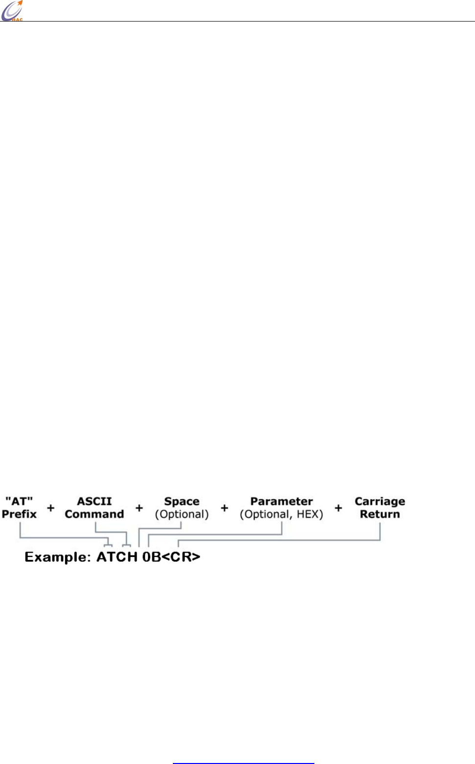
API Operation (AP parameter = 1)
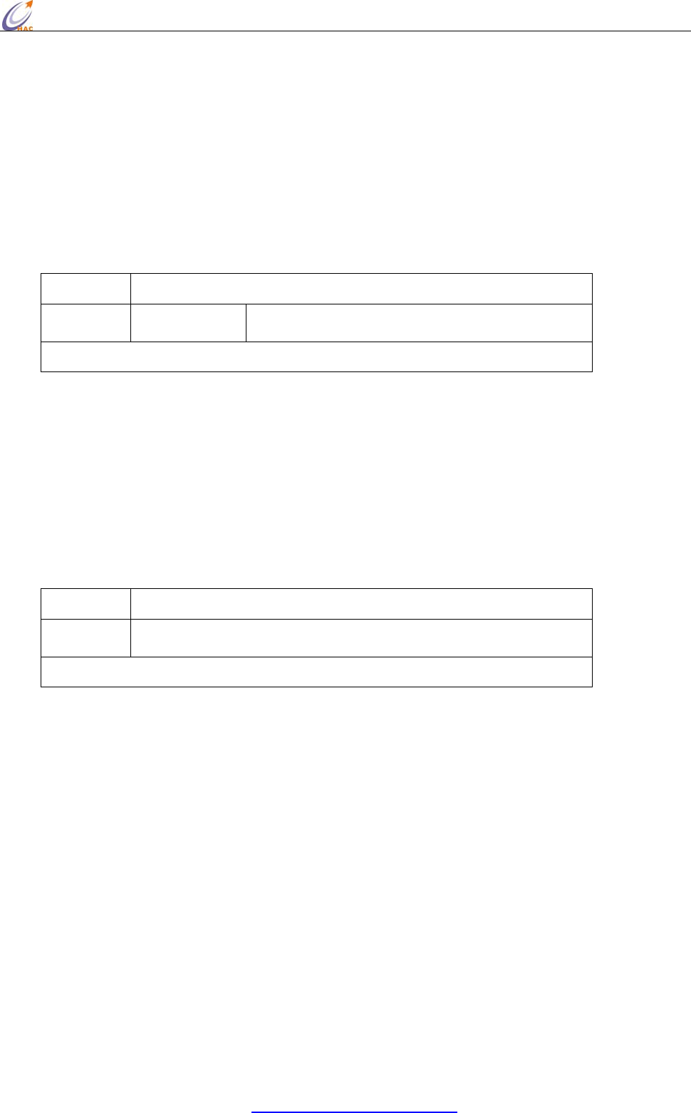
When this API mode is enabled (AP = 1), the UART data frame structure is defined as follows:
Figure UART Data Frame Structure:
MSB = Most Significant Byte, LSB = Least Significant Byte
Checksum
To test data integrity, a checksum is calculated and verified.
To calculate: Not including frame delimiters and length, add all bytes keeping only the lowest 8
bits of the result and subtract from 0xFF.
To verify: Add all bytes (include checksum, but not the delimiter and length). If the checksum is
correct, the sum will equal 0xFF.
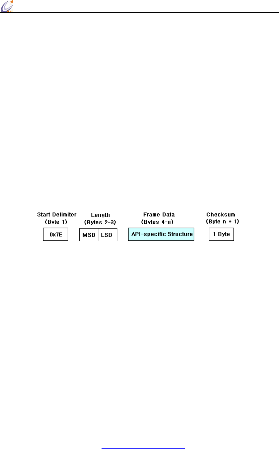
5.3.2 API Types
Frame data of the UART data frame forms an API-specific structure as follows:
HAC-Ubee manual V3.X SHENZHEN HAC TECHNOLOGY CO., LTD.
FAX:+86-755-23981007 E-MAIL:webmaster@rf-module-china.com www.rf-module-china.com -
29 -
Figure. UART Data Frame & API‐Specific Structure:
The cmdID frame (API-identifier) indicates which API messages will be contained in the cmdData
frame (Identifier-specific data). Refer to the sections that follow for more information regarding the
supported API types. Note that multi-byte values are sent big endian.
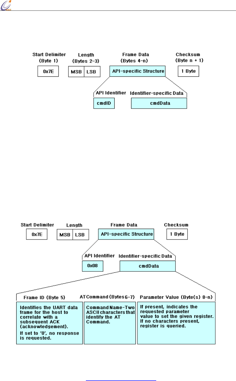
AT Command
API Identifier Value: 0x08
The “AT Command” API type allows for module parameters to be queried or set. When using this
command ID, whether the new parameter values validate at once or restart next time, it is up to the
different AT Commands. Register queries (reading parameter values) are returned immediately.
Figure. AT Command Frames
(Note that frames are identical to the “AT Command” API type except for the API identifier.)
HAC-Ubee manual V3.X SHENZHEN HAC TECHNOLOGY CO., LTD.
FAX:+86-755-23981007 E-MAIL:webmaster@rf-module-china.com www.rf-module-china.com -
30 -
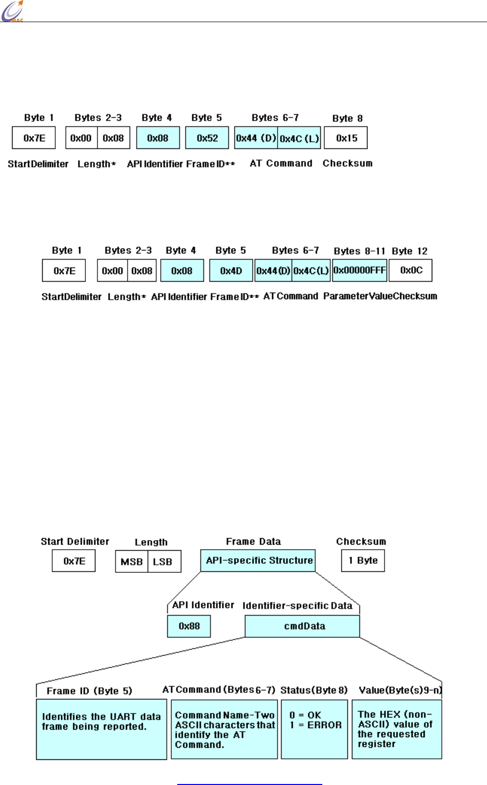
Figure. Example: API frames when reading the DL parameter value of the module.
* Length [Bytes] = API Identifier + Frame ID + AT Command
** “R” value was arbitrarily selected.
Figure . Example: API frames when modifying the DL parameter value of the module.
* Length [Bytes] = API Identifier + Frame ID + AT Command + Parameter Value
** “M” value was arbitrarily selected.
AT Command Response
API Identifier Value: 0x88
Response to previous command
In response to an AT Command message, the module will send an AT Command Response
mes-sage. Some commands will send back multiple frames. These commands will end by sending a
frame with a status of ATCMD_OK and no cmdData.
Figure . AT Command Response Frames.
HAC-Ubee manual V3.X SHENZHEN HAC TECHNOLOGY CO., LTD.
FAX:+86-755-23981007 E-MAIL:webmaster@rf-module-china.com www.rf-module-china.com -
31 -
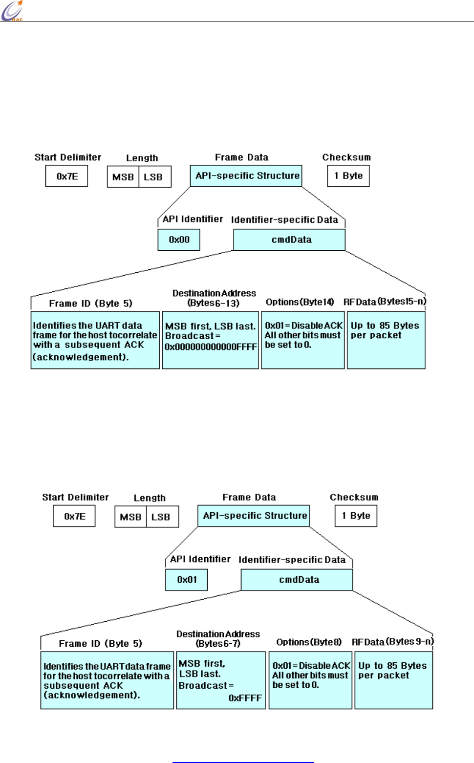
TX (Transmit) Request: 64-bit address
API Identifier Value: 0x00
A TX Request message will cause the module to send RF Data as an RF Packet.
Figure. TX Packet (64‐bit address) Frames
TX (Transmit) Request: 16-bit address
API Identifier Value: 0x01
A TX Request message will cause the module to send RF Data as an RF Packet.
Figure . TX Packet (16‐bit address) Frames
HAC-Ubee manual V3.X SHENZHEN HAC TECHNOLOGY CO., LTD.
FAX:+86-755-23981007 E-MAIL:webmaster@rf-module-china.com www.rf-module-china.com -
32 -
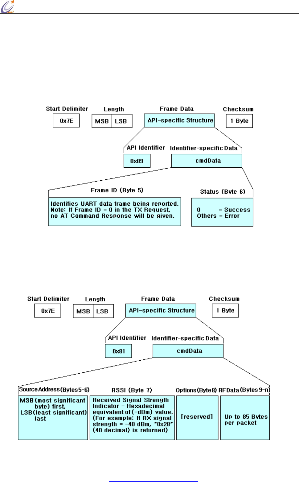
TX (Transmit) Status
API Identifier Value: 0x89
When a TX Request is completed, the module sends a TX Status message. This message will
indicate if the packet was transmitted successfully or if there was a failure.
Figure . TX Status Frames
RX (Receive) Packet: 16-bit Address
API Identifier Value: 0x81
When the module receives an RF packet, it is sent out the UART using this message type.
Figure . RX Packet (16‐bit address) Frames
5.4 Frequently Asked Questions.
5.4.1 How to broadcast transmission?

HAC-Ubee manual V3.X SHENZHEN HAC TECHNOLOGY CO., LTD.
FAX:+86-755-23981007 E-MAIL:webmaster@rf-module-china.com www.rf-module-china.com -
33 -
First users need to note that the broadcast is restricted to avoid the broadcast storm in the network.
In a Zigbee network, all the broadcast items for all the nodes should not be more than 9 items
(default value) in 3 seconds. If it exceeds the default value, the network will shield broadcast
automatically.
Broadcast under transparent mode
Under the transparent mode, if the type of destination address which can be set by ATDT command
is 16-bit address, set the 16-bit destination address as 0xFFFF which can be set by ATDS command,.
If the type of destination address is 64-bit address, set the high 32-bit destination address as
0x00000000 which can be set by ATDH command. And set the low 32-bit destination address as
0x0000FFFF which can be set by ATDL. In this way, under the transparent mode, all the data input
from the serial port of module can be transmitted by broadcast.
Broadcast under the API mode
Under the API mode, if users want to send data by 64-bit destination address, users only need to set
the address as 0x000000000000FFFF. If by 16-bit destination address, users need to set the address
as 0xFFFF. In this way, under the API mode, data can be transmitted by broadcast.
When the module transmits data by broadcast, all the other online modules in the network can
receive the data.
5.4.2 How to know a module that has been in the network?
Read the short address or 16-bit address (AT Command is ATMY.) can confirm the module
whether it is in the network. If its short address is 0xFFFE, it means it is not in the network. If its
short address is less than 0xFFFE, it means it is in the network.
Need to know that the Coordinator is always in the network. For one module, if the module has
been in a network, it will always be in the network, even the module has been restarted again, and
the short address can not be changed. Only when using the ATRN command to initialize the
network, the module will lose the network.
5.4.3 How to make the module work under the API mode after power up?
Users can use AT command to make the module enter API mode:
Enter the AT Command page of HAC Studio.
Input 3-character command sequence “+++” and wait the module returns “OK”
Input “ATAP 1<CR>” command, the module returns “OK”, it is used to setup the module work
under the API mode.
Input “ATWR <CR>” command, the module returns “OK”, it is used to save the setting to keep the

HAC-Ubee manual V3.X SHENZHEN HAC TECHNOLOGY CO., LTD.
FAX:+86-755-23981007 E-MAIL:webmaster@rf-module-china.com www.rf-module-china.com -
34 -
working mode as API mode after restart the module.
Input “ATCN <CR>” to exit from the AT Command mode. Now, the module is working on the API
mode. Even restart the module, it also enters the API mode directly.
5.4.4 Keep the 64-bit address of every module in the network has a unique address
In a Zigbee network, the 64-bit address of every module should be unique to ensure that every
module works normally in the network. If there are two modules which have the same 64-bit
address in the Zigbee network, it will cause some communication chaos. This is very important.
The 64-bit address has been set by the chip manufactory of the module in the factory. The chip
manufacture ensures the unique 64-bit address for each chip. So, we don’t recommend change the
64-bit address.
Except change 64-bit address intentionally can make that two modules have the same 64-bit address,
there are some other involuntary operations that can cause this phenomena. For example, when you
are using “Setup (API)” page of HAC-Studio setting software to setup, you read the setting of one
module, after change the module, you don’t read the 64-bit address again and setup the module
directly. In this way, the 64-bit address of last module is still in the page, so it will be written into
the new module. So it will cause two modules have the same 64-bit address.
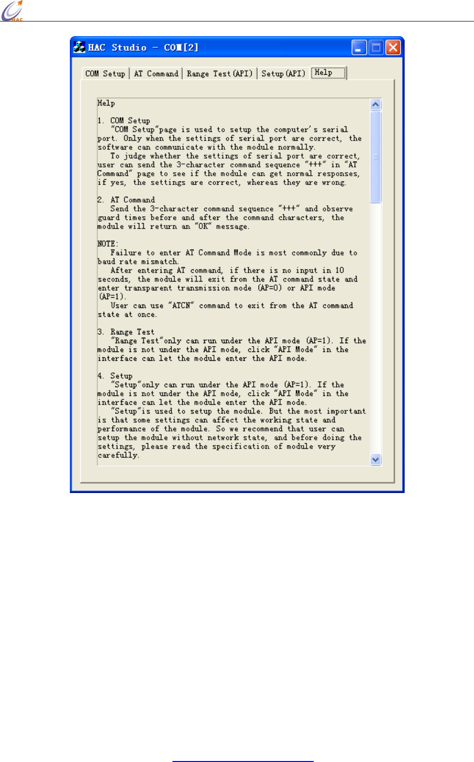
VI. Assistant Software
We offer a upper software called HAC Studio to help users to test, evaluate and setup the
HAC-Ubee module. There are 5 parts in total.
"COM Setup" page is used to setup the computer’s serial port. Only when the settings of serial port
are correct, the software can communicate with the module normally.
"AT Command" page is used to input and output AT Command.
"Range Test" is used for the communication test of module, it only can run under the API mode
(AP=1).
"Setup" is used to setup the module. But the most important is that some settings can affect the
working state and performance of the module. "Setup" only can run under the API mode (AP=1).
"Help" is the help for software. Before using the software, please read the “Help” at first.
HAC-Ubee manual V3.X SHENZHEN HAC TECHNOLOGY CO., LTD.
FAX:+86-755-23981007 E-MAIL:webmaster@rf-module-china.com www.rf-module-china.com -
35 -
VII. Appendix
Appendix 1:
1. What is Zigbee?
The ZigBee Alliance based on an open global standard is an association of companies working
together to enable reliable, cost-effective and low-power Wireless communications solutions.
ZigBee launched by ZigBee Alliance is a short-distance, low-power and low-cost wireless
communication technology. Some International well-known companies are members of ZigBee
Alliance, such as TI, Motorola, Siemens, Philips.
HAC-Ubee manual V3.X SHENZHEN HAC TECHNOLOGY CO., LTD.
FAX:+86-755-23981007 E-MAIL:webmaster@rf-module-china.com www.rf-module-china.com -
36 -
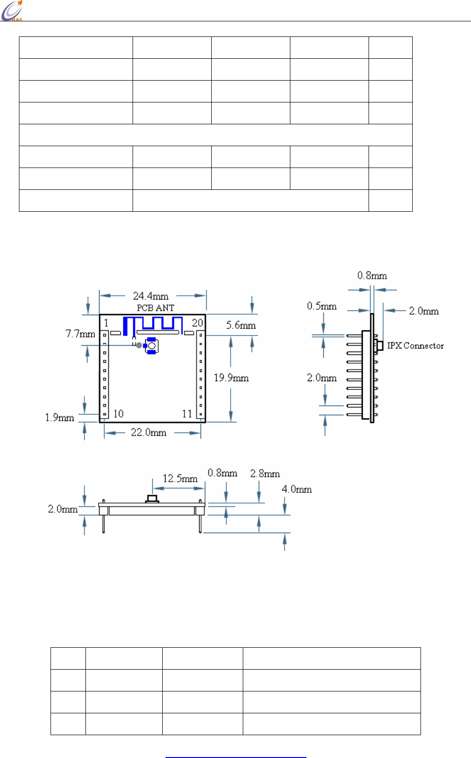
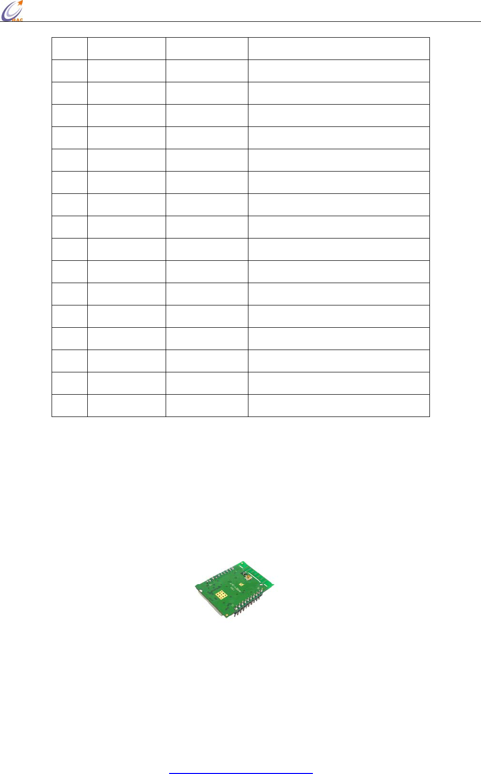
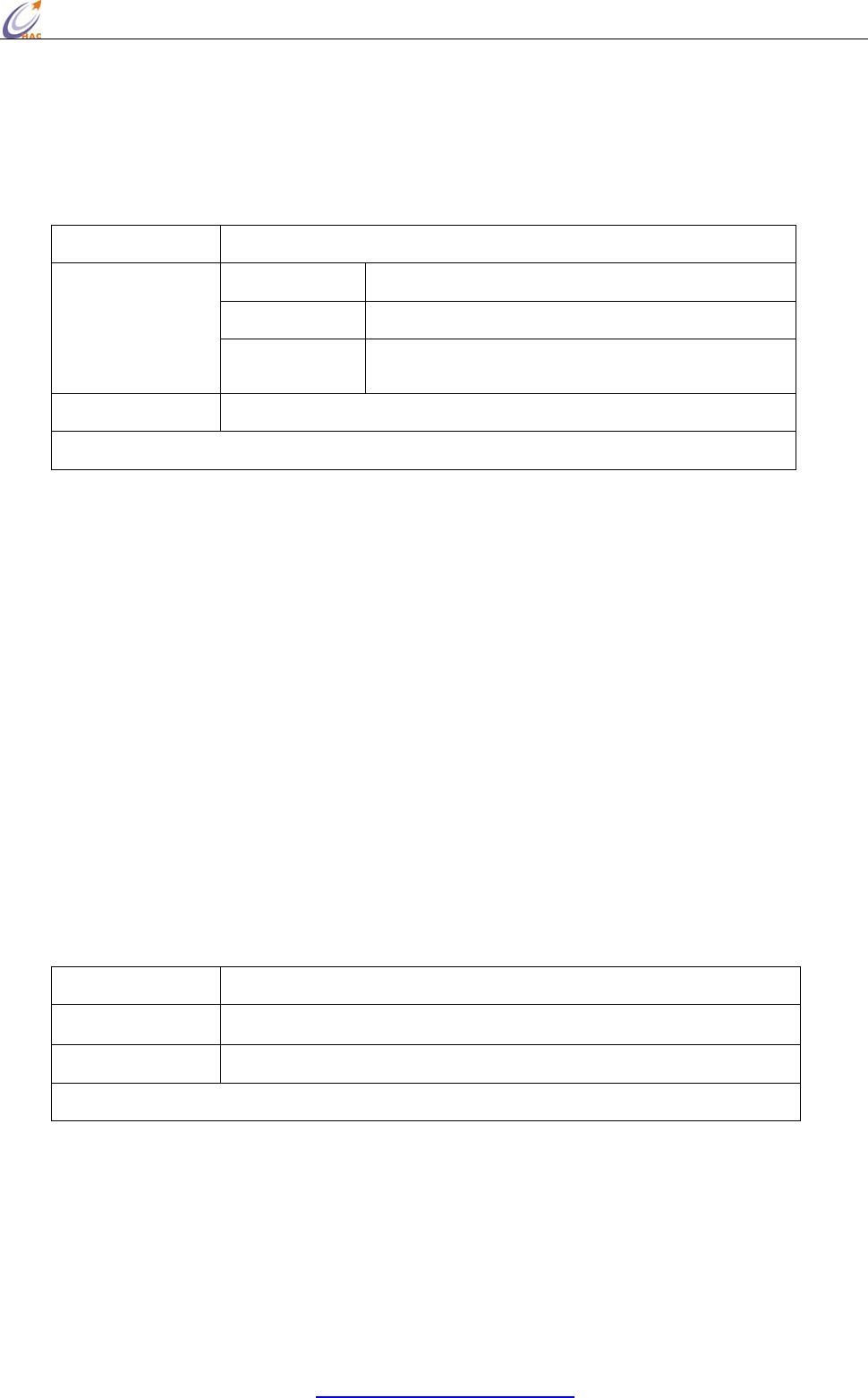
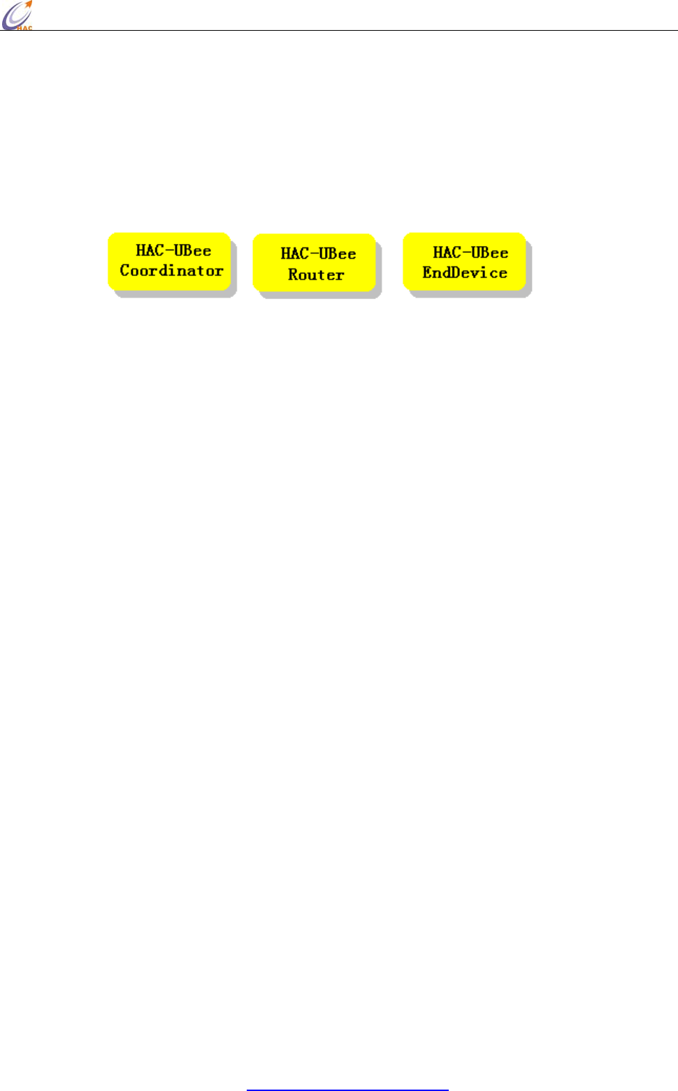
2. The sort of Zigbee module
Our ZigBee module is based on ZigBee protocol stack of TI company. According to different
functions in the network, module can be divided into three types, one is Coordinator, another one is
Router, the rest one is end device. The appearance and interface of three types are the same. Users
can distinguish them by label or by the upper software.
Picture Module Label
3. Zigbee Network
One Zigbee network only have one Coordinator, it is useed for the establishment of the network.
Only after Coordinator has been electrified for a few seconds, the network can be startup.
Coordinator is the first node in the network. Then Router can connect with Coordinator and enter
into the network. At the same time, Router in the network allows the other Router enter the network
by connecting with it. Any two nodes in the network can do point-to-point communication. At the
same time, any node can broadcast to the other nodes.
Whether a module can enter the network depends on whether it has node that has enter network in
its communication distance. If the distance between the module and its nearest node in the network
is more than its communication distance (seen in the module specification), and the node will not
communicate with any nodes in the network.
The establishment of ZigBee network can finish automatically after the module has been electrified,
User doesn’t need to operate. The order for the module’s power doesn’t seem particularly important.
After Coordinator has been electrified, ZigBee network can be built. Once a Router has entered the
network, even if the Coordinator’s power is off, the network can also work normally.
The networking for Coordinator needs to search the suitable channel. And Router enter the network
also need to search channel and network and connect. It needs some time to deal with these
processes. For Coordinator and Router, once the module enters the network, except initializing the
network, or the module will still in the network.
All modules in one network should have the same PAN ID and channel.
HAC-Ubee manual V3.X SHENZHEN HAC TECHNOLOGY CO., LTD.
FAX:+86-755-23981007 E-MAIL:webmaster@rf-module-china.com www.rf-module-china.com -
37 -
4. The 64-bit address and 16-bit address of module
The 64-bit address has been set by the chip manufactory of the module in the factory. The chip
manufacture ensures the unique 64-bit address for each chip. Before entering one Zigbee network,
its 16-bit address is 0xFFFE, it is unmeaning. Once the module enters the Zigbee network, it will
get a 16-bit address that is less than 0xFFFE. In this network, the 16-bit address is unique, except
reset the network, or 16-bit address will always belong to this module. The 16-bit address of
Coordinator in the network is fixed, it is always 0x0000.
Appendix 2:
Installation instruction for USB driver
MU series (USB to RS232)
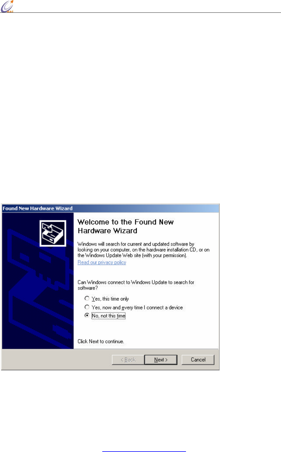
1. Connect MU USB port to the USB port of your computer. A dialog box popups as
follow. Select ‘ No, not this time’ and click ‘Next’.
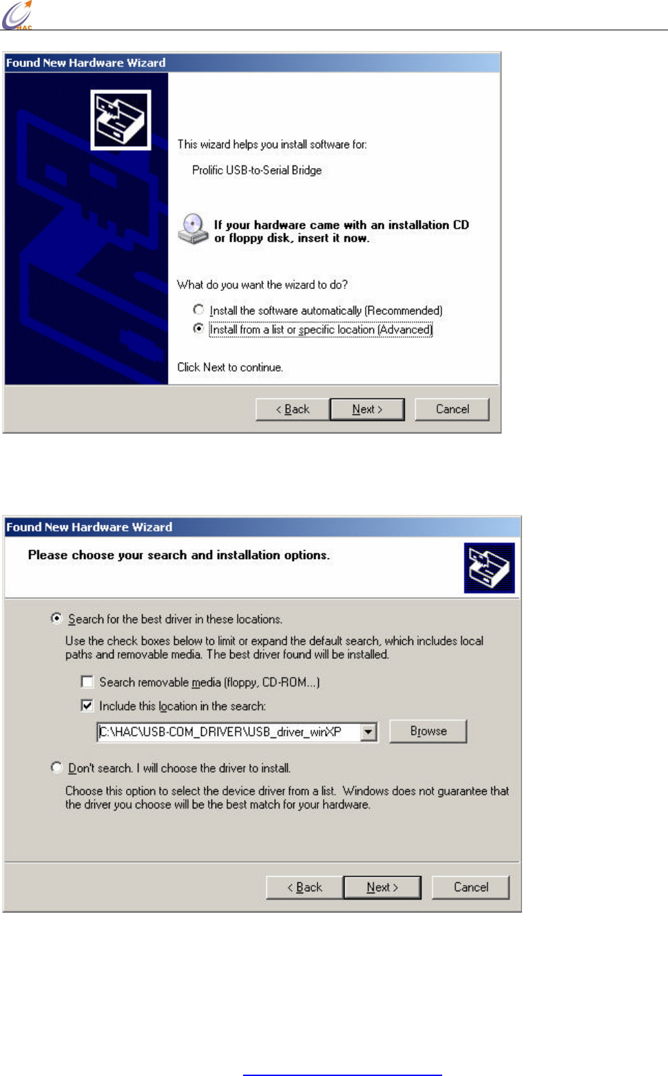
2. The next wizard box will show as below. Select ‘Advanced’ installation and click on
‘Next’ button.
HAC-Ubee manual V3.X SHENZHEN HAC TECHNOLOGY CO., LTD.
FAX:+86-755-23981007 E-MAIL:webmaster@rf-module-china.com www.rf-module-china.com -
38 -
3. In the next dialog box, please specify the path where your Windows XP driver
located, and click next after the correct path is selected.
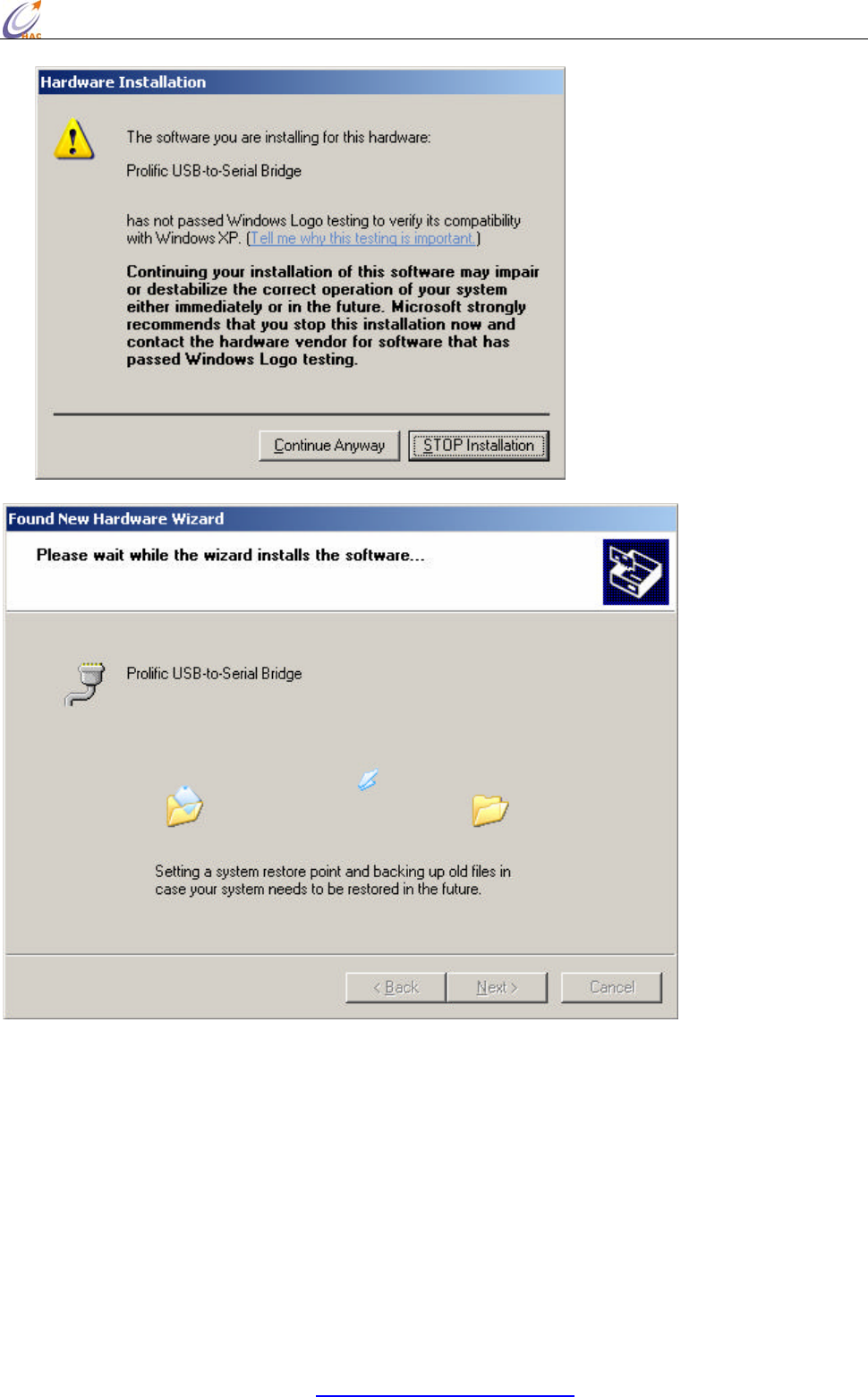
4. A warning message dialog box will appeared as below. Click ‘Continue Anyway’
button to start the installation.
HAC-Ubee manual V3.X SHENZHEN HAC TECHNOLOGY CO., LTD.
FAX:+86-755-23981007 E-MAIL:webmaster@rf-module-china.com www.rf-module-china.com -
39 -
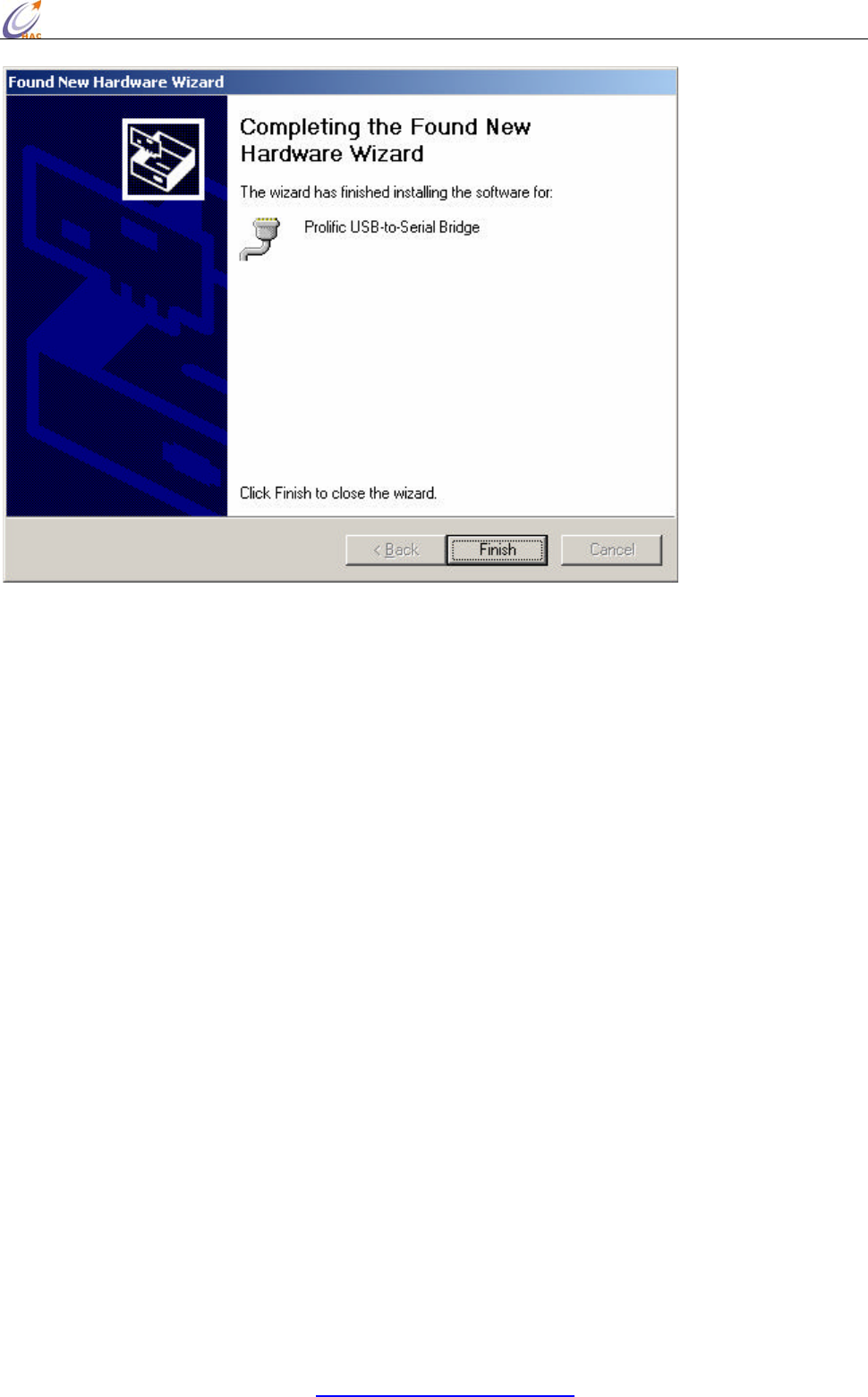
5. After the installation is completed, the following dialog box will appear. Click on the
‘Finish’ button to complete the installation.
HAC-Ubee manual V3.X SHENZHEN HAC TECHNOLOGY CO., LTD.
FAX:+86-755-23981007 E-MAIL:webmaster@rf-module-china.com www.rf-module-china.com -
40 -
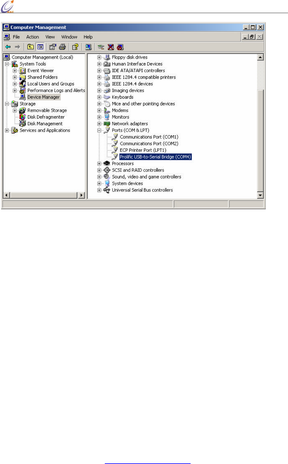
6. To verify and set the parameters of the serial port, open the Computer Manager
window and select on Device Manager on the left window. Open the COM port field
in the right window.
HAC-Ubee manual V3.X SHENZHEN HAC TECHNOLOGY CO., LTD.
FAX:+86-755-23981007 E-MAIL:webmaster@rf-module-china.com www.rf-module-china.com -
41 -
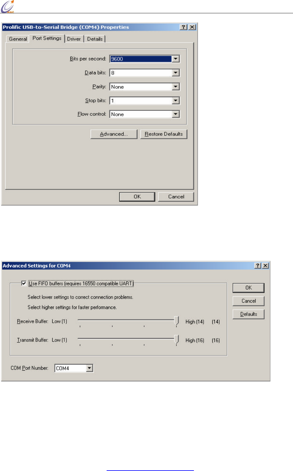
7. Right click on ‘ Prolific USB-to-Serial Bridge (COMx)’ and select on Properties. Make
sure that the parameters of the properties dialog box has all the fields set as below.
HAC-Ubee manual V3.X SHENZHEN HAC TECHNOLOGY CO., LTD.
FAX:+86-755-23981007 E-MAIL:webmaster@rf-module-china.com www.rf-module-china.com -
42 -
8. Open additional setting by click on ‘Advanced’ button on the properties dialog box.
Double check and make sure that the advanced setting for selected COM ports has
the following settings. Click OK when it’s done.
Now, the configuration of the serial port has been done. You may use the COM4 or whatever the
COM port you have installed to transmit data. One last thing for using the radio modem is that,
remember to check the baud rate and parity bit of COM port must be the same as the Smart device.