HACH LANGE LXG440 Probe for water analysis with rfid interface User Manual DOC023 53 90137
HACH LANGE GmbH Probe for water analysis with rfid interface DOC023 53 90137
LXG440_UsMan

DOC023.53.90137
AN-ISE sc ammonium and nitrate combination sensor
USER MANUAL
07/2010, Edition 1
© HACH Company, 2010. All rights reserved. Printed in Germany

3
Table of Contents
Section 1 Specifications..................................................................................................................... 5
1.1 Dimensions ........................................................................................................................................ 6
Section 2 General Information.......................................................................................................... 7
2.1 Safety information............................................................................................................................... 7
2.1.1 Hazard information in these operating instructions.................................................................... 7
2.1.2 Precautionary labels .................................................................................................................. 7
2.2 General information about the probe .................................................................................................. 8
2.3 Theory of operation............................................................................................................................. 9
Section 3 Installation......................................................................................................................... 11
3.1 Unpack the probe ............................................................................................................................. 11
3.2 Unpacking the sensor cartridge........................................................................................................ 12
3.2.1 Assembling the storage container including sensor cartridge.................................................. 13
3.2.2 Removing the cartridge from the transport container............................................................... 14
3.3 Probe assembly................................................................................................................................ 15
3.4 Installation of the cleaning unit (optional) ......................................................................................... 17
3.5 Installation of the probe in the sample flow....................................................................................... 18
3.5.1 Position of the probe on the mount.......................................................................................... 19
3.5.2 Probe installation example....................................................................................................... 19
3.6 Connect the probe to the sc controller (non-hazardous location) with screw fittings........................ 20
Section 4 Operation........................................................................................................................... 21
4.1 How to use an sc controller .............................................................................................................. 21
4.2 Sensor setup..................................................................................................................................... 21
4.3 Sensor data logger ........................................................................................................................... 21
4.4 Sensor diagnostics menu ................................................................................................................. 21
4.5 Sensor setup menu........................................................................................................................... 22
4.6 Calibration/Matrix correction............................................................................................................. 25
4.6.1 Sensor code calibration ........................................................................................................... 26
4.6.2 Matrix correction via LINK2SC................................................................................................. 26
4.6.3 Matrix correction overview ....................................................................................................... 26
4.6.4 Performing the matrix correction.............................................................................................. 27
4.6.4.1 MATRIX 1 correction (1 point matrix correction)............................................................. 27
4.6.4.2 Value correction 1 ........................................................................................................... 28
4.6.4.3 Value correction 2 ........................................................................................................... 29
4.6.4.4 MATRIX 2 correction (2 point matrix correction)............................................................. 30
Section 5 Maintenance ..................................................................................................................... 31
5.1 Maintenance schedule...................................................................................................................... 31
5.2 Clean the sensor............................................................................................................................... 31
5.2.1 Polish the chloride electrode.................................................................................................... 31

4
Table of Contents
5.3 Replace the sensor cartridge ............................................................................................................32
5.4 Storage..............................................................................................................................................34
Section 6 Troubleshooting ...............................................................................................................35
6.1 Error messages.................................................................................................................................35
6.2 Warnings ...........................................................................................................................................36
6.3 Troubleshooting ..............................................................................................................................37
6.3.1 Troubleshooting during operation.............................................................................................37
6.3.2 Troubleshooting during calibration ...........................................................................................38
Section 7 Replacement parts and accessories .......................................................................39
7.1 Replacement Parts............................................................................................................................39
7.2 Accessories.......................................................................................................................................39
7.3 Validation accessories.......................................................................................................................39
7.4 Corresponding documentation ..........................................................................................................39
Section 8 Contact ..............................................................................................................................41
Section 9 Limited warranty ..............................................................................................................43
Section 10 Certification.....................................................................................................................45
10.1 Certification .....................................................................................................................................45
Appendix A Modbus Register ........................................................................................................47
Index ......................................................................................................................................................49

5
Section 1 Specifications
These are subject to change without notice.
General Information
Measuring method Potentiometric measurement using ion-selective electrodes (ISE) for ammonium,
potassium, nitrate and chloride, reference system
Measuring range
0 to 1000 mg/L [NH4–N]
0 to 1000 mg/L [K+]
0 to 1000 mg/L [NO3–N]
0 to 1000 mg/L [Cl–]
Precision 5% of the measured value + 0.2 mg/L1 (ammonium and nitrate)
Reproducibility 5% of the measured value + 0.2 mg/L1 (ammonium and nitrate)
Response time (90 %) < 3 minutes (5 to 50 mg/L NO3–N/NH4–N)
Measuring interval Continuous
pH range pH 5 to pH 9
Calibration methods Sensor code for sensor cartridge
1 and 2 point value correction or matrix correction
Power consumption 1 W
Power supply Via sc controller
Data transfer Via sc controller
Ambient data
Typical environment Used in the biological phase of municipal wastewater treatment
Storage temperature Sensor: –20 to 60 °C (–4 to 140 °F)
Sensor cartridge: 5 to 40 °C (41 to 104 °F)
Operating temperature Air: –20 to 45 °C (–4 to 113 °F)
Sample temperature +2 to 40 °C (35 to 104 °F)
Max. Flow velocity < 4 m/s
Max. sensor immersion
depth/pressure
Can be immersed at a depth of 0.3 to 3.0 m [1 to 10 ft];
maximum pressure: 0.3 bar (4.4 psi).
Max. Compressed air output during
cleaning unit operation 3.1 bar (45 psi)
General information about the probe
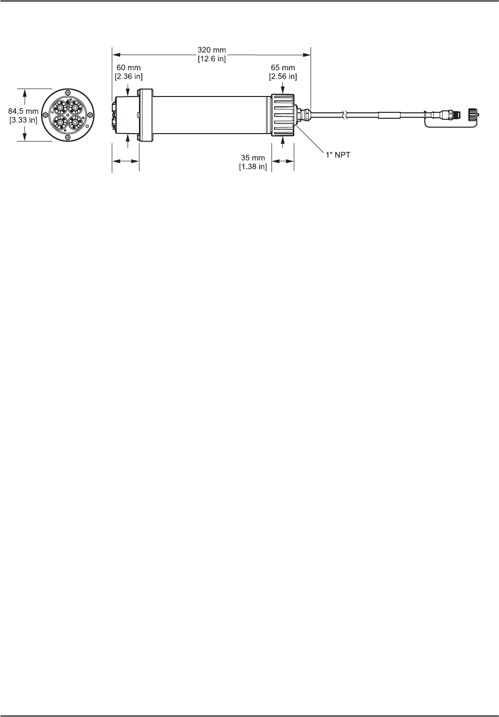
Probe dimensions 320 mm × 84.5 mm (12.6 × 3.3 in.) (Length × Ø)
Refer to Figure 1, Page 6.
Length of probe cable
Standard: 10 m [33.8 ft]
Extension cables are available as an option in the following lengths:
5, 10, 15, 20, 30, 50 m [16.4, 33.8, 49.2, 65.6, 98.4, 164 ft].
Maximum overall length: 100 m [328 ft]
Probe weight Approximately 2380 g (63.6 oz)
Wetted materials
Only for immersed installations:
Probe: stainless steel (1.4571), ASA + PC, silicon, PVC and PU
Sensor cartridge: PVC, POM, ABS, stainless steel (1.4571), NBR
Optional cleaning unit: TPE, PUR, stainless steel (1.4571)
Installation angle 45° +/– 15° vertical in flow direction
1 With standard solutions and ISE electrodes under laboratory conditions
6
Specifications
1.1 Dimensions
Figure 1 Dimensions of stainless steel probe
DANGER
WARNING
CAUTION
NOTICE
7
Section 2 General Information
2.1 Safety information
Please read the entire operating instructions before the instrument is unpacked, set up or
put into operation. Pay attention to all danger and caution statements. Failure to do so
could result in serious injury to the operator or damage to the equipment.
To make sure that the protection provided by this instrument is not impaired, do not use or
install this instrument in any manner other than that specified in these operating
instructions.
2.1.1 Hazard information in these operating instructions
Note: Information that supplements points in the main text.
2.1.2 Precautionary labels
Read all labels and tags attached to the instrument. Personal injury or damage to the
instrument could occur if not observed. A symbol, if noted on the instrument, will be
included with a danger or caution statement in the operating instructions.
Indicates a potentially or imminently hazardous situation that, if not avoided, results in death or
serious injury.
Indicates a potentially or imminently hazardous situation that, if not avoided, could result in death
or serious injury.
Indicates a potentially hazardous situation that may result in minor or moderate injury.
Indicates a situation that, if not avoided, could result in damage to the instrument. Information that
requires special emphasis.
This symbol, if noted on the instrument, references the user manual for operation and/or safety information.
Electrical equipment marked with this symbol may not be disposed of in European domestic or public disposal
systems after 12 August 2005. In conformity with European local and national regulations (EU Directive
2002/96/EC), European electrical equipment users must now return old or end-of life equipment to the manufacturer
for disposal at no charge to the user.
Note: For return for recycling, please contact the equipment manufacturer or supplier for instructions on how to
return end-of-life equipment, manufacturer-supplied electrical accessories, and all auxiliary items for proper disposal.
8
General Information
2.2 General information about the probe
The probe was developed for use in municipal wastewater applications.
The AN-ISE sc probe (please refer to Figure 2) with ion-selective electrodes (ISE probe) is
a continuously operating online process probe for directly measuring ammonium and
nitrate in reservoirs. It operates without reagents and requires no further processing of the
sample. The ammonium/nitrate ions are measured using an ion-selective electrode.
The only wearing part is the sensor cartridge (please refer to Figure 3, Page 9) (order
number LZY694). The sensor cartridge consists of the ion-selective electrodes for
ammonium and potassium (compensation electrode for ammonium) or nitrate and chloride
(compensation electrode for nitrate), a pHD reference system and a temperature sensor
for temperature compensation.
An additional cleaning unit designed for automatically cleaning the sensor cartridge
membranes can be ordered separately. Refer to the instruction sheet supplied with the
cleaning unit.
The manufacturer recommends using the High Output Air Blast system for the
compressed air supply (refer to 7.2 Accessories, page 39); this is a compressor in
weather-proof plastic housing.
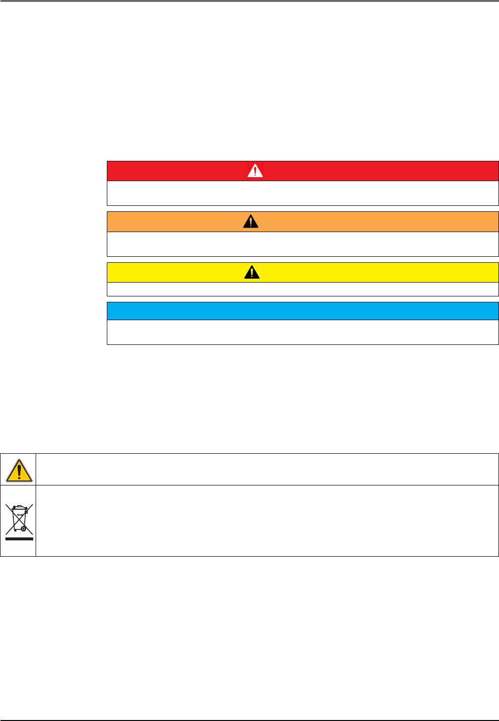
Figure 2 AN-ISE sc probe
1Sensor cartridge 3Probe body
2Fixing bolt for sensor cartridge 4Union nut
4
1
2
3
9
General Information
2.3 Theory of operation
The AN-ISE sc probe uses the ion-selective electrode to measure ammonium ions (NH4+)
and nitrate ions (NO3–) in a wastewater sample. Common interfering factors due to
potassium, chloride and temperature are compensated for by means of the relevant
built-in electrodes. The reference system is designed using pH-differential technology and
is therefore particularly stable in terms of drift and contamination.
Ion-selective electrodes have a special membrane to which only a specific type of ion can
adhere. As a result an ion-specific potential forms on the membrane surface. To measure
a potential difference, a reference system is required that will not be affected by the
sample to be measured.
The CARTRICALTM technology reduces cross sensitivity by calibrating not only the
individual electrodes against each other, but also the measuring electrodes with the
compensation electrodes and the reference; this is carried out at the factory.
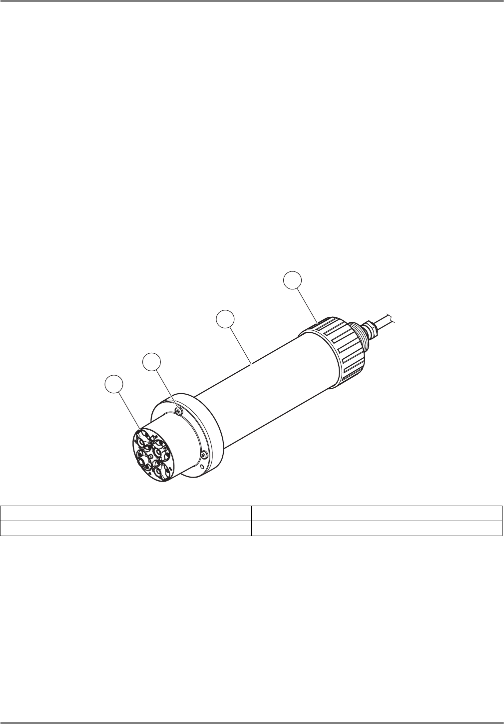
Figure 3 Sensor cartridge
1Ammonium electrode 5Reference system
2Nitrate electrode 6Temperature sensor
3Potassium electrode 7Marker hole for assembling the probe
4Chloride electrode

10
General Information
NOTICE
11
Section 3 Installation
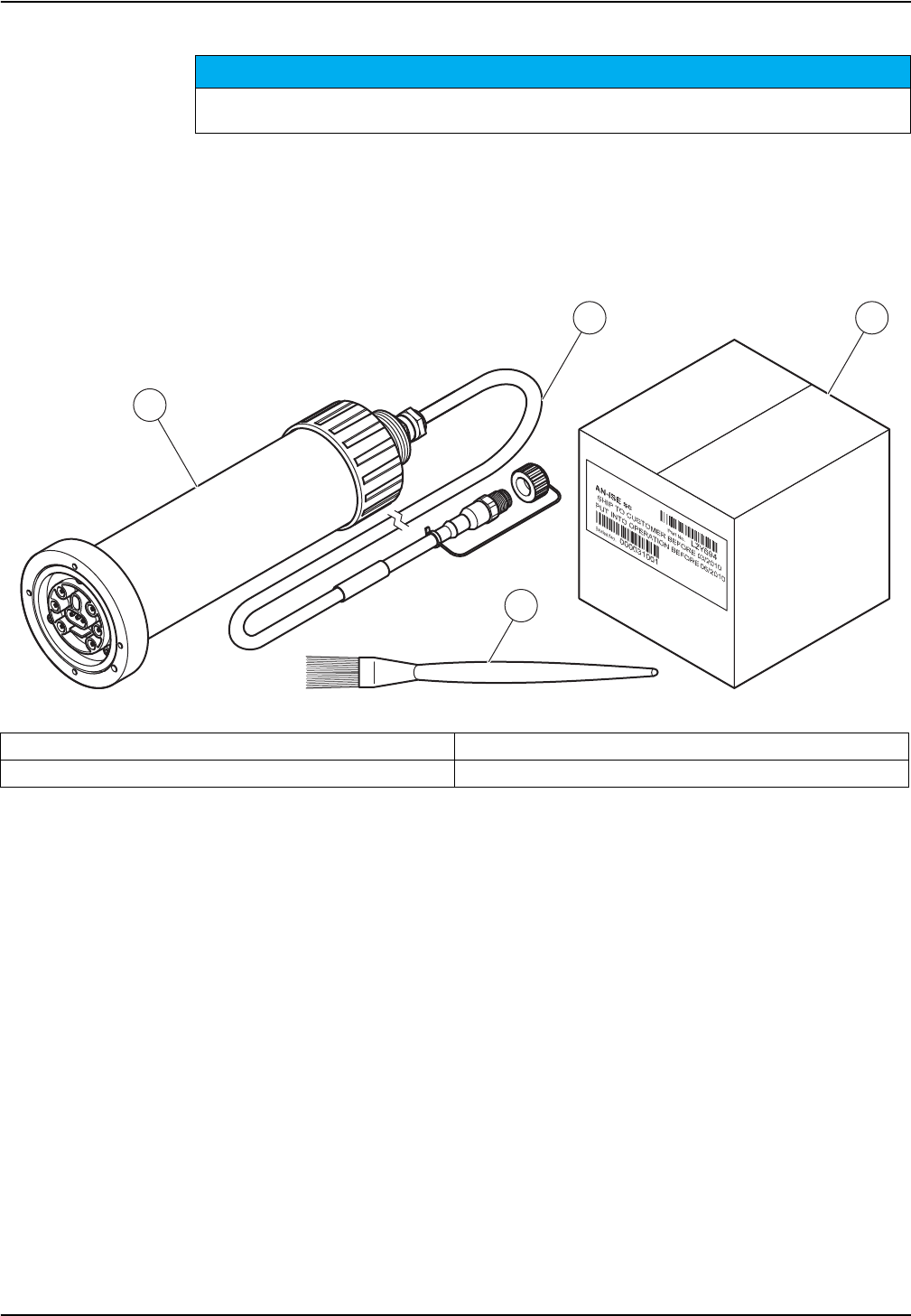
3.1 Unpack the probe
Remove the probe from the shipping container and inspect it for damage. Verify that all
items listed in Figure 4 are included. If any items are missing or damaged, contact the
manufacturer or distributor.
Only qualified personnel should conduct the tasks described in this section of the operating
manual.
Figure 4 Product contents
1Probe 3Sensor cartridge packaging
2Probe cable 4Cleaning brush
1
23
4
NOTICE
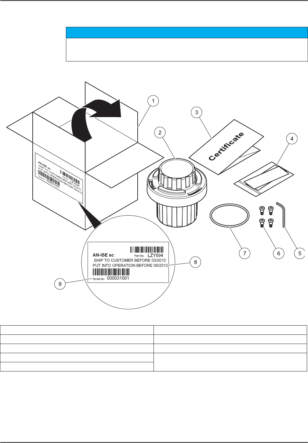
Figure 5 Storage container packaging
12
Installation
3.2 Unpacking the sensor cartridge
Avoid touching the membrane on the sensor cartridge or damage to the sensor may occur.
Make a note of the date on the sensor cartridge certificate. It is not an expiration date, but indicates
the optimum date to put the sensor cartridge into operation to ensure a maximum service life.
1Sensor cartridge packaging 6Socket head screws
2Storage container for sensor cartridge 7Black gasket
3Test certificate for cartridge with sensor code 8Latest date to put into operation
4Polishing paper for chloride electrode 9Serial Number
5Socket head wrench
2
3
4
5
1
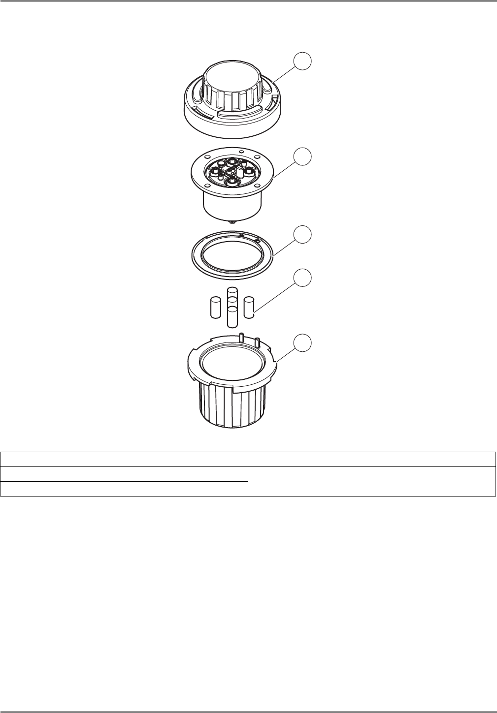
Figure 6 Storage container for sensor cartridge1
13
Installation
3.2.1 Assembling the storage container including sensor cartridge
1Storage container 4Sensor cartridge
2Sponges soaked in storage solution 5Lid with bayonet coupling
3Black gasket
1 Save items 1, 2, 3 and 5 for subsequent storage of the sensor cartridge.
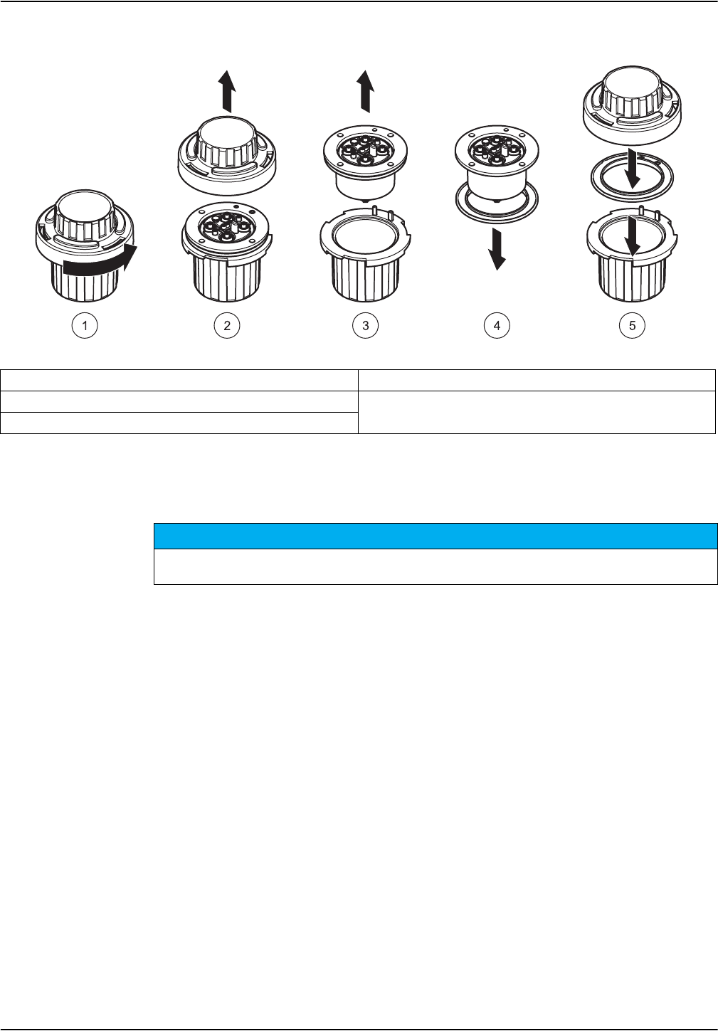
Figure 7 Opening the storage container
NOTICE
14
Installation
3.2.2 Removing the cartridge from the transport container
Note: This black gasket is not required for installation. It is advisable to keep the black gasket in
the sensor cartridge storage container.
1Release bayonet coupling 4Remove black gasket
2Remove lid 5Insert black seal in storage container and close the lid.
3Take out sensor cartridge
The sensor cartridge must not be in contact with the air for more than 30 minutes. Make sure that
the electrodes do not dry out.
NOTICE
NOTICE
15
Installation
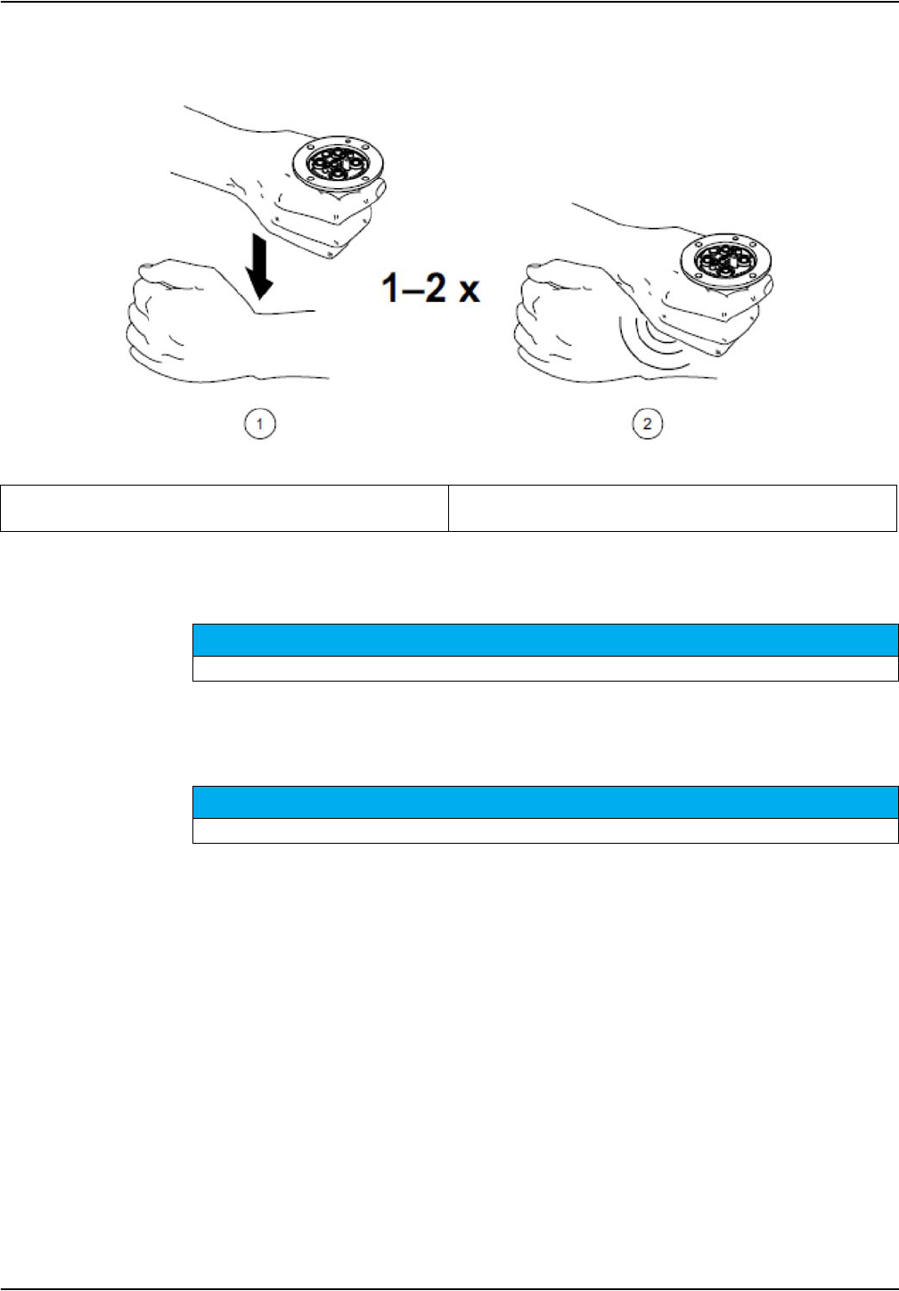
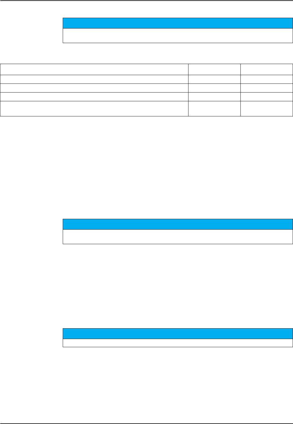
Please complete the following movement when you have unpacked the cartridge in order
to moisten the inside of the membranes.
3.3 Probe assembly
1. Place the black gasket Figure 10, Page 17 in the recess on the sensor body.
2. Make sure that the black gasket is correctly positioned.
Figure 8 Knocking the air out of the sensor cartridge
1Hold the sensor cartridge in one hand with the
membranes facing downward.
2Now hit sharply downward over your other hand.
Avoid touching the membranes on the sensor cartridge or damage to the sensor may occur.
The black gasket prevents sensor damage caused by moisture penetration.
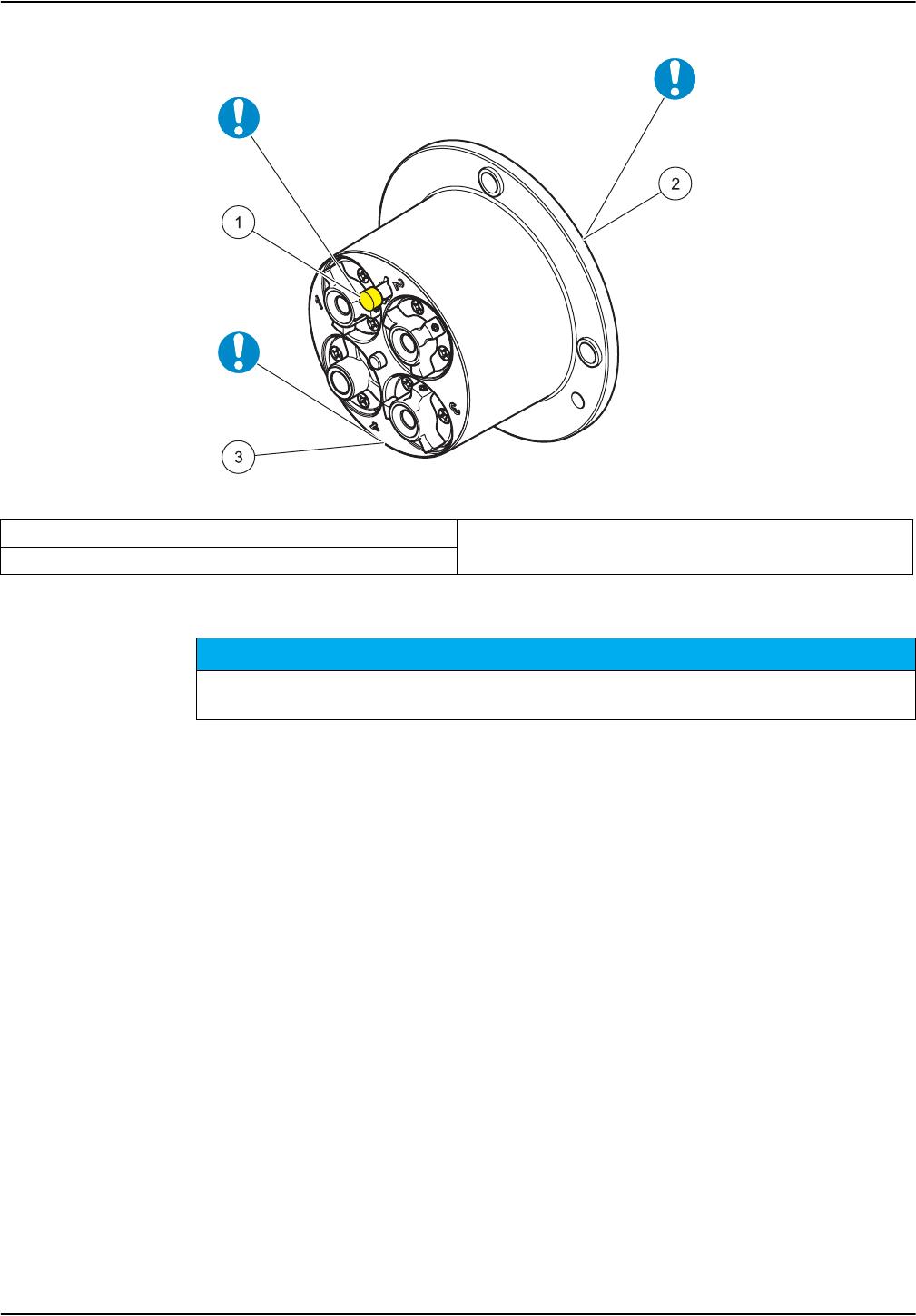
Figure 9 Sensor cartridge
NOTICE
16
Installation
3. Align the marker hole on the sensor cartridge with the marker hole on the probe
adapter (refer to Figure 10, Page 17)
4. Place the 4 socket head screws in the corresponding screw holes and tighten gently
with the long side of the wrench. Then cross-tighten the screws by hand with the short
side of the wrench. Only use the screws supplied.
1Reference system cap 3Front side with membranes
2Rear side with contacts
The sensor cartridge must not be in contact with the air for more than 30 minutes.
The contacts in the sensor cartridge must be dry and must not become contaminated.
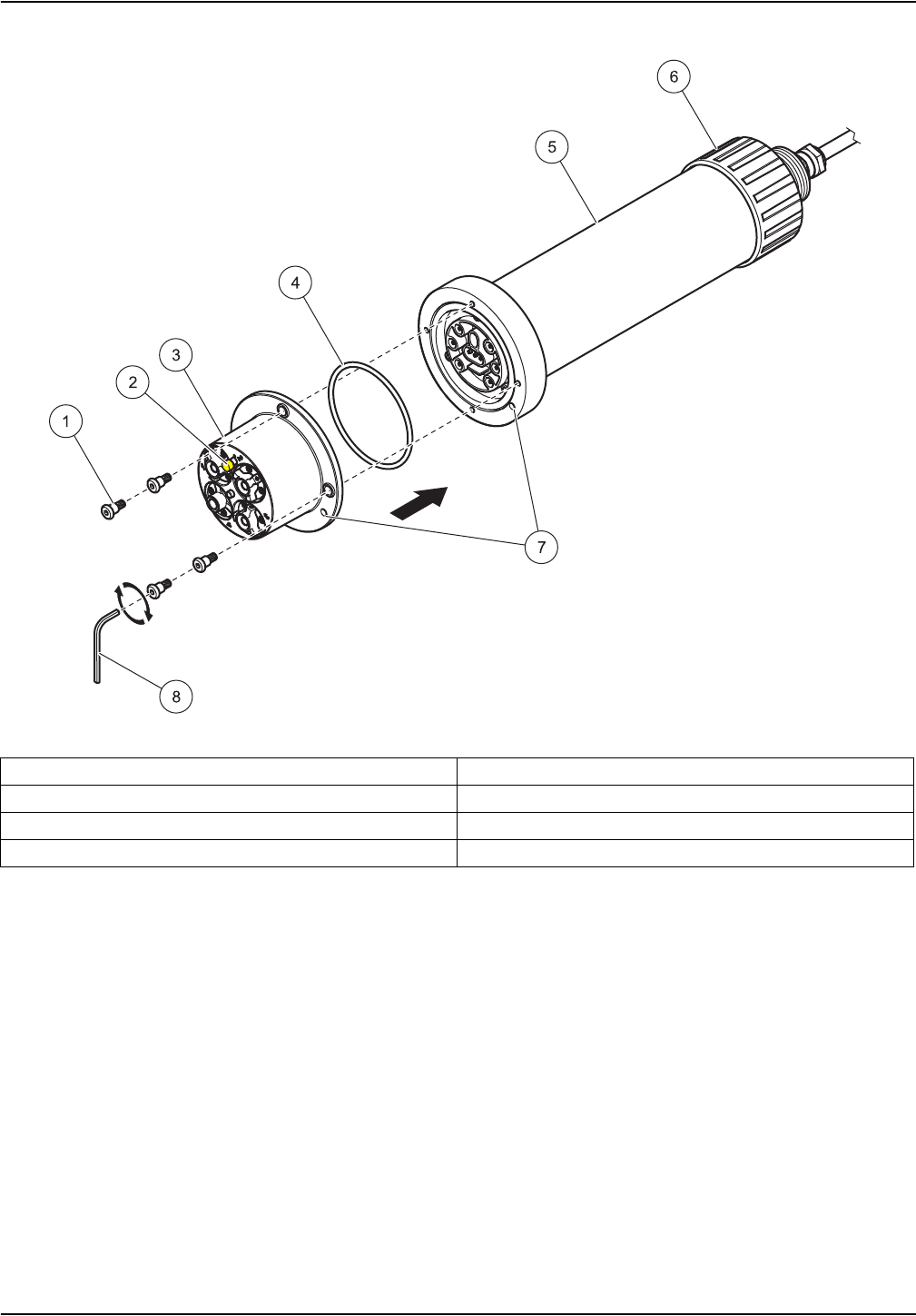
Figure 10 Probe assembly
17
Installation
3.4 Installation of the cleaning unit (optional)
Please refer to the installation instructions for the cleaning unit for information on how to
install this on the probe.
Use the relay control on the sc controller to set the cleaning interval.
Select RTC (Real Time Clock) as the signal source. For details on more advanced relay
configuration, please refer to the User Manual for the relevant sc controller.
1Socket head screw 5Probe housing
2Reference system cap 6Union nut
3Sensor cartridge 7Marker hole
4Black gasket 8Socket head wrench

NOTICE
18
Installation
3.5 Installation of the probe in the sample flow
There are mounts with separate installation instructions available for installation of the
probe, with or without a cleaning unit, to suit a number of different requirements.
Always observe the following prior to installation:
•The probe must be aligned with the bracket, as described in section 3.5.1, page 19.
•Position the probe at a distance of at least 200 mm (7.87 in.) from the tank wall.
•When the probe is attached with a chain mount, make sure that the probe cannot
strike the tank wall.
•Immerse the probe at an angle of approx. 45° ± 15°.
•Make sure that the probe is fully immersed.
•When using the cleaning unit refer to the supplied Instruction Sheet.
Please handle the sensor cartridge carefully and avoid contact with the membranes when installing
the sensor.
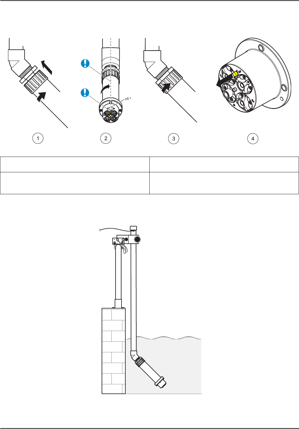
Figure 11 Installing the probe
Figure 12 Example of probe installation with rail mount
19
Installation
3.5.1 Position of the probe on the mount
The probe must be attached in a specific position on the mount:
3.5.2 Probe installation example
1Installation of the AN-ISE sc in the bracket. 45° adapter
and transition piece should be preassembled.
3Attaching the aligned probe to the bracket using the
union nut
2Aligning the probe using the colored reference system
cap. The salt bridge should be oriented upward (12 o'
clock, +/- 5°).
4Removing the reference system cap
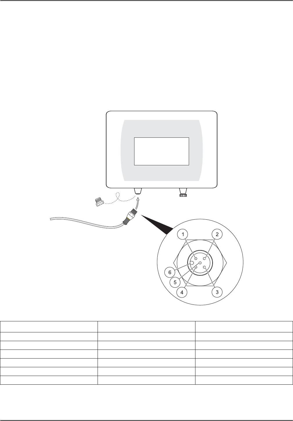
Figure 13 Connecting the probe to the sc controller with the screw fitting
Number Description Cable color
1+12 VDC Brown
2Ground Black
3Data (+) blue
4Data (–) White
5Shield Shield (gray)
6Guide
20
Installation
3.6 Connect the probe to the sc controller (non-hazardous location) with
screw fittings
The probe cable is supplied with a screw fitting with reverse polarity protection (refer to
Figure 13, Page 20). Retain the connector cap to seal the connector opening in case the
probe ever needs to be removed. Additional extension cables are available to increase the
probe cable length.
1. Unscrew the protective cap from the socket on the controller.
2. Insert the connector in the socket and hand-tighten the union nut.
Note: The middle connection on the sc1000 controller must not be used for probes as this is
reserved for the display module.
SENSOR STATUS
21
Section 4 Operation
4.1 How to use an sc controller
The probe can be used with all sc controllers. Become familiarized with the controller's
functions before using the probe.
4.2 Sensor setup
When the sensor is connected for the first time, the sensor serial number is displayed as
the name of the sensor. To change the sensor name.
1. Open the MAIN MENU.
2. Select SENSOR SETUP and confirm.
3. Select the corresponding sensor and confirm.
4. Select CONFIGURE and confirm.
5. Select EDIT and confirm.
6. Edit the name and confirm to return to the CONFIGURE menu.
7. Check the sensor configuration and adjust as needed to meet requirements.
8. Go back to the MAIN MENU or the Measurement mode display.
4.3 Sensor data logger
Every sc-sensor provides a data memory and event memory within the sc controller. The
data memory is used to store measurement data at preset intervals; the event memory
stores events such as configuration changes, alarms and warning conditions. Both
memories can be read in CSV format (refer to the operating instructions for the sc
controller).
4.4 Sensor diagnostics menu
AN-ISE sc
ERROR LIST Displays all actual error codes.
WARNING LIST Displays all actual warnings.
22
Operation
4.5 Sensor setup menu
SENSOR SETUP
AN-ISE sc
CALIBRATE
MATRIX CORR
Matrix correction options.
The most recently used menu is displayed.
The currently active corrections are shown in Information.
NONE No MATRIX CORR. is activated
MATRIX 1 1 point matrix correction
NH4 + NO3 1 point matrix correction for ammonium and nitrate
NH4 1 point matrix correction for ammonium
NO3 1 point matrix correction for nitrate
NH4 + K 1 point matrix correction for ammonium and potassium
NO3 + CL 1 point matrix correction for nitrate and chloride
NH4+K NO3+CL 1 point matrix correction for ammonium, potassium, nitrate and chloride
TAKE SAMPLE IMMEDIATELY AND
ANALYSE IN LABORATORY
Information window: When this window appears, the sample must be
taken immediately and then analyzed in the laboratory.
VALUE CORR. 1
Perform 1 point value correction.
The most recently used menu is displayed.
The currently active corrections are shown in Information.
NH4–N Select parameter for the 1 point value correction
NO3–N
VALUE POINT Enter the values for the 1 point value correction
(below for the example of NH4)
AN-ISE SC NH4–N Enter the displayed ammonium value
AN-ISE SC K Enter the displayed potassium value
LAB NH4–N Enter the laboratory ammonium value
ENTRY COMPLETE Confirm the values entered
CORR-RESULT Display the correction results
VALUE CORR. 2 Perform 2 point value correction
NH4–N Select parameter for the 2 point value correction
NO3–N
VALUE POINT 1 Enter the values for the 2 point value correction (first point) (below for
the example of NH4)
AN-ISE SC NH4–N Enter the displayed ammonium value
AN-ISE SC K Enter the displayed potassium value
LAB NH4–N Enter the laboratory ammonium value
ENTRY COMPLETE Confirm the values entered
VALUE POINT 2 Enter the values for the 2 point value correction (second point) (below
for the example of NH4)
AN-ISE SC NH4–N Enter the displayed ammonium value
AN-ISE SC K Enter the displayed potassium value
LAB NH4–N Enter the laboratory ammonium value
ENTRY COMPLETE Confirm the values entered
CORR-RESULT Display the correction results

23
Operation
SENSOR SETUP
FURTHER CORR. Other matrix correction options
None No FURTHER CORR. is activated
MATRIX 2 A 2 point matrix correction can be performed here
NH4 Parameter selection for the MATRIX2 correction.
NO3
MEAS CONC 1 Saves the currently measured measurement for the first point
DATE Displays the date of the current correction of the first point
CONC. LABVALUE 1 Entry and display of reference value for the first point
MEAS CONC 2 Saves the currently measured measurement for the second point
DATE Displays the date of the current correction of the second point
CONC. LABVALUE 2 Entry and display of the reference value for the second point
HIST. CORR. Selection of one of the last corrections performed
SENSOR CODE The sensor code can be activated or entered here
INPUT Entry of the sensor code
ACTIVATION Activates the sensor code for the individual channels
NH4 + K Activate the sensor code for ammonium and potassium
NO3 + CL Activate the sensor code for nitrate and chloride
NH4+K NO3+CL Activate the sensor code for ammonium, potassium, nitrate and
chloride
FACTORY CALIBRATION Activates factory calibration
ENTER CORR. The laboratory values of the last matrix correction can be changed
ENTER LABVALUE (displayed when MATRIX 1
or MATRIX 2 is performed)
Enter the laboratory values if MATRIX 1 or MATRIX 2 has been
selected
AMMONIUM Enter the labatory value for ammonium
NITRATE Enter the laboratory value for nitrate
POTASSIUM Enter the laboratory value for potassium
CHLORIDE Enter the laboratory value for chloride
ENTRY COMPLETE Confirm the values entered
CORR-RESULT Display the correction results
NH4–N Displays whether or not the ammonium correction was successful
NO3–N Displays whether or not the nitrate correction was successful
K+ Displays whether or not the potassium correction was successful
CL Displays whether or not the chloride correction was successful
INFORMATION Information on the matrix correction used per parameter
NH4–N Matrix correction used for ammonium
NO3–N Matrix correction used for nitrate
K+ Matrix correction used for potassium
CL Matrix correction used for chloride
4.5 Sensor setup menu (Continued)

24
Operation
SENSOR SETUP
CONFIGURE
EDIT NAME Enter or edit the name.
Up to 10 alphanumeric characters
MEAS UNITS Select either mg/L or ppm as the measurement unit
PARAMETERS Select NH4–N/NO3–N or NH4/NO3
TEMP UNITS Selection of °C or °F as temperature unit
TEMP OFFSET Enter a temperature offset
RESPONSE TIME Entry of the response time (30 sec to 300 sec)
DATALOG INTRVL Select the data log interval (OFF, 30 sec, 1 min, 2 min, 5 min, 10 min,
15 min and 30 min), 5 min is the factory setting
K+ COMPENSATE
Select automatic potassium compensation:
On
Off
0 = compensation OFF
0.1–2000 mg/L K+ = Fixed compensation value
SET K+ CONC Only shown when K+ COMPENSATE is OFF
CL COMPNSATE
Select automatic chloride compensation:
On
Off
0 = compensation OFF
0.1–2000 mg/L CL = Fixed compensation value
SET CL CONC Only shown when CL COMPNSATE is OFF
FACTORY CONFIG Resets the configuration on the factory setting
DIAG/TEST
SENSOR INFO Information on the connected sensor
SENSOR NAME Name of the connected sensor
EDIT NAME Serial number or name of the measurement location
SERIAL NUMBER Serial number of the connected sensor
SENSOR TYPE Instrument designation of the connected sensor
CODE VERS Software version
CAL DATA Data of the selected MATRIX correction and information about slope
and offset of the individual channels, for example
NH4–N Matrix correction selected for ammonium
NO3–N Matrix correction selected for nitrate
K+ Matrix correction selected for potassium
CL Matrix correction selected for chloride
SIGNALS Signals and measurements of the individual measurement channels
AMMONIUM Display the signals and measurement results for ammonium
NITRATE Display the signals and measurement results for nitrate
POTASSIUM Display the signals and measurement results for potassium
CHLORIDE Display the signals and measurement results for chloride
REF. ELECTRODE Displays the signals and measurement results for the reference system
MV RAW Display the signals and measurement results for MV RAW
IMPED STATUS Display the signals and measurement results for impedance
4.5 Sensor setup menu (Continued)
25
Operation
4.6 Calibration/Matrix correction
The four electrodes with the reference system of the compact sensor cartridge were
calibrated with one another at the factory using special standard solutions (CARTICALTM).
However, the membranes on the ion-selective electrodes are not 100% selective due to
other substances that may affect the measurement. Perform a matrix correction (refer to
4.6.4 on page 27) to compensate for other ions present on the ISE electrodes.
Potassium has the largest interference effect on the ammonium membrane, while chloride
has the largest effect on the nitrate membrane. The AN-ISE sc sensor compensates for
this with the aid of a built-in potassium/chloride electrode.
Cross sensitivities between ammonium, potassium/nitrate and chloride are automatically
eliminated. Solids do not interfere with the measurement. Due to matrix effects, correction
and validation cannot be performed with standard solutions. A matrix correction can be
carried out quickly and easily at any time.
SENSOR SETUP
TEMP Display the signals and measurement results for temperature
HUMIDITY Display the signals and measurement results for humidity
RFID Display the signals and measurement results for RFID
CAL DAYS Display the age of the last matrix correction for ammonium and nitrate
AMMONIUM Display the age of the last matrix correction for ammonium
NITRATE Display the age of the last matrix correction for nitrate
SERVICE
TEST CARTRIDGE Perform a sensor check with the test cartridge
TEST CARTRIDGE FERTIG? DRÜCKE ENTER
TEST CARTRIDGE Display whether the individual sensor channels are OK or not
DIAG/TEST Displays whether or not DIAG/TEST is OK
GNDROD Displays whether or not GNDROD is OK
REF Displays whether or not REF channel is OK
NO3 Displays whether or not NO3 channel is OK
NH4 Displays whether or not NH4 channel is OK
ORP Displays whether or not ORP channel is OK
CL Displays whether or not CL channel is OK
K+Displays whether or not K channel is OK
TEMP Displays whether or not temperature channel is OK
CHANGE CARTR. Follow the menu process
CLEANING
NOTICE
Follow the menu process
4.5 Sensor setup menu (Continued)
A matrix correction may only be performed if the sensor has been immersed in the corresponding
wastewater matrix for over 12 hours. This is the minimum time required to adapt the ISE
membranes to the wastewater matrix.

26
Operation
4.6.1 Sensor code calibration
The sensor code is a calibration code and is delivered with the sensor cartridge certificate.
It contains the factory calibration described in section 4.6 on page 25 for the sensor
cartridge.
Instruments with automatic sensor code recognition (LXG440.99.0000x) read this
automatically and assume the Cartrical calibration.
Instruments without automatic sensor code recognition (LXG440.99.0001x) require the
sensor code to be entered during the initial setup and whenever a new sensor cartridge is
activated. If the sensor code certificate has been lost, please carry out factory calibration
(under the sensor code menu) as a temporary solution.
After activating the code, the sensor is fully calibrated but not yet adapted to the specific
matrix of the relevant application on a wastewater treatment plant. At least 12 hours must
elapse before a matrix correction is performed to allow the cartridge to adapt to the
specific matrix.
To change the sensor code:
1. Select SENSOR MENU>AN-ISE SC>CALIBRATE>FURTHER CORR.>SENSOR
CODE>ENTER
2. Enter the sensor code.
3. Press ENTER to confirm and activate the sensor code. The day meter for the cartridge
is set to zero.
All old calibration data are now overwritten with the new calibration data from the sensor
code. The sensor code data are checked by the system. If an error is indicated, check the
sensor code and if necessary repeat the entry of the sensor code.
4.6.2 Matrix correction via LINK2SC
The LINK2SC procedure offers a secure method of data exchange between process
probes and LINK2SC-compatible photometers using an SD memory card or via a local
area network (LAN). There are two different options are available:
a. The pure laboratory control measurement
b. A matrix correction that involves the measurement data generated in the
laboratory being used to correct the probe
During a pure control measurement, the measurement data is transferred from the prove
to the photometer where it is then archived together with the photometric reference data
that has been recorded.
During a matrix correction, the reference data generated in the laboratory is transferred to
the probe where is used for the correction.
The matrix correction process requires operating steps to be completed on the sc
controller and on a LINK2SC-compatible photometer.
Please refer to the LINK2SC user manual for a detailed description of the LINK2SC
procedure.
When using the LINK2SC software, sections 4.6.3 and 4.6.4 are not relevant.
4.6.3 Matrix correction overview
The AN-ISE sc sensor offers different options
(refer to Table 1) for correcting the sensor value with laboratory values (as a reference
value).

Table 1 AN-ISE sc sensor correction options
Correction Option Application
MATRIX 1
VALUE CORR. 1
VALUE CORR. 2
MATRIX 2
HIST. CORR.
27
Operation
The laboratory value of the water sample is entered as nitrate-nitrogen (NO3–N) or as
ammonium-nitrogen (NH4–N). This laboratory value replaces the prior value measured by
the sensor.
4.6.4 Performing the matrix correction
Note: Take laboratory value measurements or reference values promptly or, alternatively, take these
from the stabilized sample. This will prevent changes in sample concentration, as time is a factor in
comparative tests.
Refer to 7.3 Validation accessories, page 39 for recommended laboratory measurement
tests.
4.6.4.1 MATRIX 1 correction (1 point matrix correction)
Proceed as follows to perform MATRIX 1:
1. Select SENSOR MENU>AN-ISE SC>CALIBRATE>MATRIX CORR.
2. Select MATRIX 1 from the selection window and press ENTER.
3. Select the parameters you wish to correct and confirm by pressing ENTER. Selection
options:
NH4 + NO3; NH4; NO3; NH4 + K;
NO3 + Cl; NH4 + K NO3 + Cl.
A MATRIX 1 is the most commonly used correction option and performs a 1 point matrix
correction for ammonium and/or nitrate (4.6.4.1 on page 27). It is advisable to perform a MATRIX1 as
the first correction. The Matrix1 correction can be performed both with and without correction of the
compensation electrodes (potassium or chloride); in most cases, it is sufficient to perform it without
correction of the compensation electrodes. A correction featuring potassium and chloride is only
necessary if a high level of accuracy is required. With a MATRIX1, a sample must be taken when the
correction is triggered and analyzed in the laboratory. The MATRIX1 is activated when the laboratory
value is entered.
Value correction 1 (correction at one concentration point) corresponds to a MATRIX1 correction
with an alternative entry format.
Comparison values between AN-ISE sc and the laboratory can be collected over a period of around
a week with this correction. The correction can be performed at a later stage.
Value correction 2 (correction at 2 different concentration points) should be performed if dynamic
concentration fluctuations are present over at least half a decade1 and a MATRIX1 or VALUE
CORR. 1 does not achieve a sufficiently accurate result.
Comparison values between AN-ISE sc and the laboratory can be collected over a period of around
a week with this correction. The correction can be performed at a later stage.
The MATRIX 2 correction corresponds to a VALUE CORR.2, but uses an alternative entry
format and is recommended if there is a dynamic process with a large nitrate/ammonium fluctuation
over at least half a decade1. With a MATRIX2, a sample must be taken for both points when the
correction is triggered and analyzed in the laboratory. The MATRIX2 is activated when the laboratory
value is entered.
Return to one of the last matrix and value corrections performed if a correction has not produced
a successful result.
1 Examples of half a decade: The concentration of nitrogen nitrate shifts between 1 and 5 mg NO3–N or
between 5 and 25 mg/L NO3–N. (conc2 = (conc1 x 10)/2)
CALIBRATE
MATRIX CORR
FURTHER CORR.
INFORMATION

28
Operation
The sensor saves the current values of the selected parameters at this point.
4. Take a water sample immediately from the closest point possible to the sensor. Filter
the sample as quickly as possible and carry out a prompt laboratory analysis of the
selected parameters, as the measurement value can change quickly.
When the laboratory value has been determined, proceed as follows:
5. Select SENSOR MENU>AN-ISE SC>CALIBRATE>ENTER LABVALUE
6. The laboratory values for the parameters can only be entered if the MATRIX1
correction has been selected beforehand. Once the laboratory values have been
entered, select ENTRY COMPLETE to confirm.
When the entered laboratory value is confirmed, the matrix correction is activated.
7. Once the correction is activated, the result CORR-RESULT is shown.
Note: This process must always be carried out in full to make sure the matrix correction is
completed successfully.
If a correction does not produce a successful result, calculations are made with the previous
correction.
4.6.4.2 Value correction 1
The one-point value correction VALUE CORR. 1 offers the option of retrospectively
performing a matrix correction at one point (MATRIX1).
1. Take several samples with different concentrations on various days, preferably within
one week. Analyze the samples in the laboratory. During the time the samples are
being taken, the sample temperature should be around a maximum of 5 °C, as
temperature changes are not taken into account in the value correction.
2. Make a note of the two values measured in the samples and displayed for the
parameters to be corrected (ammonium and potassium values, or nitrate and chloride
values)
3. Also note the laboratory values measured for ammonium or nitrate.
These three values form the correction point.
4. From the values taken, select a correction point that lies in the middle of the expected
concentration range.
5. Go to the sensor menu and select CALIBRATE>MATRIX CORR>VALUE CORR. 1 and
confirm by pressing ENTER.
6. Select the parameter (NH4–N or NO3–N) that requires correction.
7. Enter the three values for the sought correction point and confirm with ENTRY
COMPLETE to activate the correction.
Correction result CORR-RESULT is shown.
Note: If a correction does not produce a successful result, calculations are made with the previous
correction.
After successful completion of value correction, the corrected value is shown as the display value for
ammonium or nitrate the next time the menu is opened.
MATRIX 1
TAKE SAMPLE
IMMEDIATELY
AND ANALYSE
IN LABORATORY
CALIBRATE
MATRIX CORR
FURTHER CORR.
ENTER LABVALUE
INFORMATION
CALIBRATE
MATRIX CORR
FURTHER CORR.
INFORMATION
VALUE POINT
AN–ISE SC NH4–N
AN–ISE SC K
LAB NH4–N
ENTRY COMPLETE

29
Operation
4.6.4.3 Value correction 2
The two-point value correction VALUE CORR. 2 makes it possible to perform a subsequent
2-point correction (MATRIX2) to achieve higher accuracy for a larger concentration range.
Note: Value correction 2 and MATRIX 2 are comparable from a calculation perspective.
1. Take several samples on various days with different concentrations, preferably within
a week, and perform an analysis of the samples in the laboratory. During the time the
samples are being taken, the sample temperature should be around a maximum of 5
°C, as temperature changes are not taken into account in the value correction.
Note: The VALUE CORR. 2 concentrations should be within a range of over half a decade. The
following formula can assist in the calculation of the half decade:
2. Make a note of the two values measured with the sensor in the samples and displayed
for the parameters to be corrected (ammonium and potassium values, or nitrate and
chloride values).
3. Also note the laboratory value measured for ammonium or nitrate.
All three values form one of the two correction points.
4. Look for two correction points where the laboratory values are at least half a decade
apart and display typical operating conditions for the installation.
5. Go to the sensor menu and select CALIBRATE>MATRIX CORR>VALUE CORR. 2 then
confirm with ENTER.
6. Select the parameter (NH4–N or NO3–N) that requires correction.
Note: Only one parameter can be corrected at a time. If both need to be corrected, the procedure
must be performed again.
7. Enter the three values for the first correction point and confirm with ENTRY
COMPLETE.
8. To activate the correction, enter the three values for the second correction point and
confirm with ENTRY COMPLETE.
Correction result CORR-RESULT is shown.
Note: If a correction does not produce a successful result, calculations are made with the previous
correction. After successful completion of value correction, the corrected value is shown as the
display value for ammonium or nitrate the next time the menu is opened.
CALIBRATE
MATRIX CORR
FURTHER CORR.
INFORMATION
Conc2 >= Conc1 × 10
2
VALUE POINT 1
AN–ISE SC NH4–N
AN–ISE SC K
LAB NH4–N
ENTRY COMPLETE
VALUE POINT 2
AN–ISE SC NH4–N
AN–ISE SC K
LAB NH4–N
ENTRY COMPLETE

30
Operation
4.6.4.4 MATRIX 2 correction (2 point matrix correction)
Proceed as follows to perform MATRIX 2:
1. Select SENSOR MENU>AN-ISE SC>CALIBRATE>FURTHER CORR..
2. Select MATRIX 2 from the selection window and press ENTER.
3. Select the parameters requiring a two point matrix correction.
4. Select the point to be corrected first.
5. SELECT MEAS CONC 1 or MEAS CONC 2
6. Take a water sample from the closest point possible to the sensor. Filter this sample
promptly and perform an immediate laboratory analysis of the selected parameters.
The measurement value can change very quickly:
When the laboratory value has been determined, proceed as follows:
7. Select SENSOR MENU>ANISE SC>CALIBRATE>FURTHER CORR.>MATRIX 2
8. Select the parameters to be corrected with the laboratory value entry:
9. Enter the laboratory reference value and confirm.
The MATRIX2 CORR. is activated when the entry is confirmed for both points.
AMMONIUM
CONC MEAS1
DATE
CONC. LABVALUE.1
MEAS CONC 2
DATE
CONC. LABVALUE 2
NOTICE
Maintenance task 30 days112 months
NOTICE
NOTICE
31
Section 5 Maintenance
Note: Do not test the sensor with the usual NH4-N or NO3-N standard solutions as the ion strength
of normal solutions is not high enough.
5.2 Clean the sensor
1. Clean the sensor cartridge with the soft brush supplied.
2. Clean the probe body (not the sensor cartridge) with a sponge or brush.
3. Rinse the sensor with clean, lukewarm water.
5.2.1 Polish the chloride electrode
Polish the chloride electrode if it looks heavily coated/contaminated.
After polishing, a new nitrate + chloride MATRIX1 correction should be performed after
12 hours.
Only qualified personnel should conduct the tasks described in this section of the operating
manual.
5.1 Maintenance schedule
Clean the probe2 x
Replace the sensor cartridge3, 4x
Check probe for damage x
Compare the measured value with a reference laboratory analysis and correct
the values as required via a matrix correction3 x
1 Recommended: Weekly during the first month of operation
2 The frequency of cleaning depends on the application. Some applications may require cleaning to take place more or less
frequently.
3 In typical operating conditions, a different interval may be required depending on the specific application and local conditions.
4 Sensor cartridges are wear parts and are not covered by the instrument warranty.
Do not touch the membranes with fingers. Do not clean the sensor cartridge with sharp objects that
may cause scratches and do not use any chemical cleaning agent.
Only use the LZY671 polishing paper supplied.
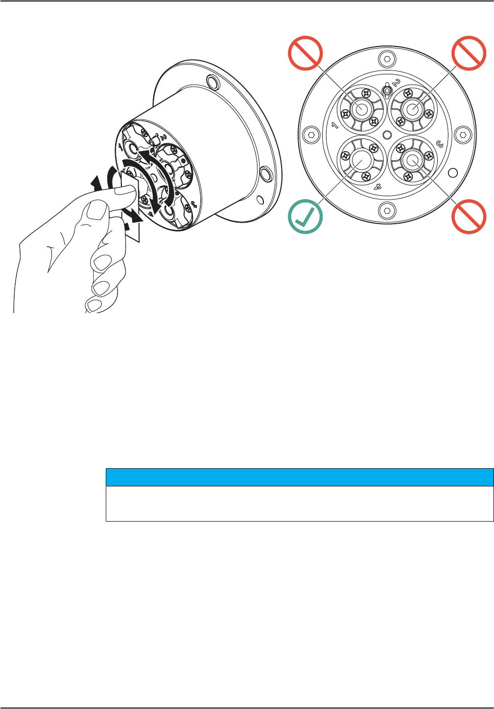
Figure 14 Chloride electrode
NOTICE
32
Maintenance
5.3 Replace the sensor cartridge
The sensor cartridge is replaced as described below and in Figure 15, Page 33.
1. Replace the cartridge using menu point ANISE SC>DIAG/TEST>SERVICE>CHANGE
CARTR..
2. Clean the probe and thoroughly dry the sensor cartridge and probe adapter.
3. Loosen the 4 socket head screws.
.
4. Pull the sensor cartridge out of the probe adapter and dispose of the old sensor
cartridge as per the applicable regulations.
5. Make sure that a new black gasket is installed every time the sensor cartridge is
replaced. Before the gasket is installed, clean the surface that faces the cartridge and
the groove for the gasket.
6. Insert the new sensor cartridge into the probe adapter. Observe the marker hole on
the sensor cartridge flange and the probe adapter.
7. Secure the sensor cartridge with the 4 socket head screws.
8. The sensor code (calibration data) is automatically read for instruments with automatic
recognition (LXG440.99.0000x). For instruments with non-automatic recognition
(LXG440.99.0001x), enter the new sensor code manually (refer to certificate).
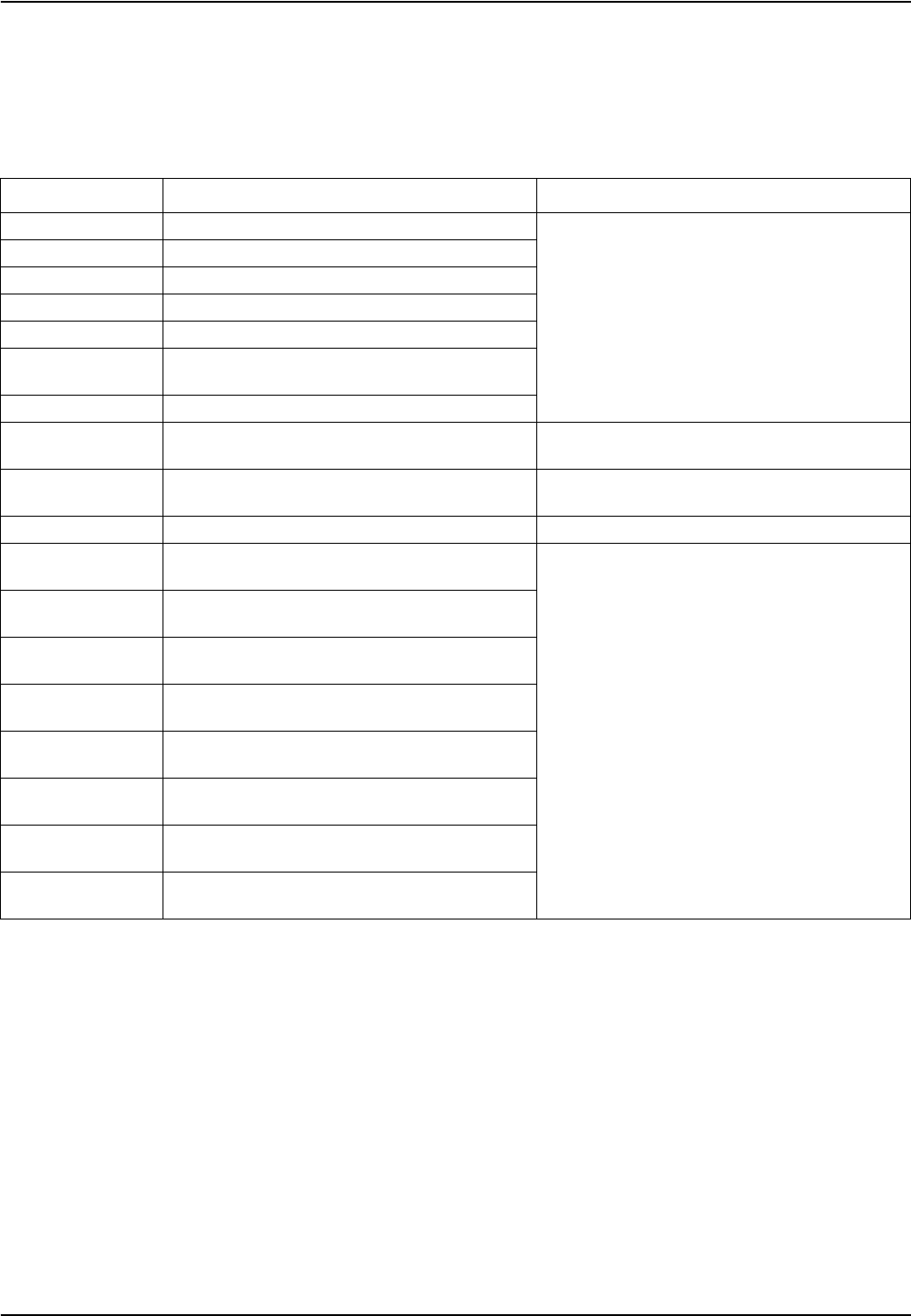
The sensor cartridge must point downward such that no water can run into the probe adapter. Pay
attention to the contacts between the probe and the sensor cartridge. The contacts have to remain
dry.
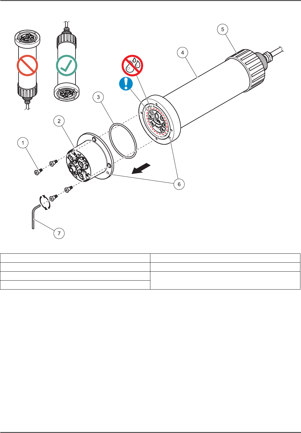
Figure 15 Replace the sensor cartridge
33
Maintenance
1Socket head screw 5Union nut
2Sensor cartridge 6Marker hole
3Gasket 7Socket head wrench
4Sensor

NOTICE
NOTICE
34
Maintenance
5.4 Storage
Take the probe out of the sample flow and clean thoroughly.
Short term storage
Keep the membranes and the reference system wet (DO NOT USE DISTILLED OR
DEMINERALIZED WATER). Drinking water is advised.
This will help avoid long response times when the probe is placed back in the sample flow.
Otherwise, the correct operation of the probe is no longer guaranteed.
Long term storage
Check the membranes and ensure they are still moist every 2–4 weeks, depending on
environmental conditions.
Note: A storage container is supplied to keep the sensor cartridge moist. Keep sensor cartridge
capped within the storage container during short and long term storage. Refer to
Section 1 Specifications, Page 5 for storage temperatures.
Probe and sensor cartridge
Detach the cartridge and use the supplied storage container in the event of long-term storage.
Moisten the little sponge in the storage container with drinking water (DO NOT USE DISTILLED
OR DEMINERALIZED WATER) and make sure that the ISE membranes of the sensor cartridge
remain wet. Attach the reference system cap.
Pay attention to the contacts between the probe and the sensor cartridge. The contacts must be
dry.
35
Section 6 Troubleshooting
6.1 Error messages
When the sensor is experiencing an error condition, the sensor reading on the
measurement screen will flash and the relays and analog outputs associated with this
sensor will be held. Errors are defined in Table 2.
Table 2 Error messages
Displayed errors Definition Resolution
NH4 mV RANGE! Ammonium mV value is out of measuring range
See 6.3.1 Troubleshooting during operation,
Page 37.
K+ mV RANGE! Potassium mV value is out of measuring range
NO3 mV RANGE! Nitrate mV value is out of measurement range
CL mV RANGE! Chloride mV value is out of measurement range
REF1 mV RANGE! REF1 reference value is out of measuring range
REF2 mV RANGE! ORP electrode mV value is out of measuring
range
TEMP RANGE Temperature value out of measurement range
NO CARTRIDGE No sensor cartridge connected Connect sensor cartridge, see section 3.3,
page 15.
SENSOR CODE Sensor code calibration failed See 6.3.2 Troubleshooting during calibration,
Page 38
HUMIDITY Humidity in the probe Inform service engineer
NH4-N CONC HIGH Ammonium concentration value exceeds
measuring range
See 6.3.1 Troubleshooting during operation,
Page 37.
NH4-N CONC LOW Ammonium concentration value is below
measuring range
NO3-N CONC HIGH Nitrate concentration value exceeds measuring
range
NO3-N CONC LOW Nitrate concentration value is below measuring
range
K+ CONC HIGH Potassium concentration value exceeds
measuring range
K+ CONC LOW Potassium concentration value is below
measuring range
CL CONC HIGH Chloride concentration value exceeds measuring
range
CL CONC LOW Chloride concentration value is below measuring
range

36
Troubleshooting
6.2 Warnings
In the event of a sensor warning, all menus, relays and outputs continue to function as
normal but a warning symbol lights up.
Warnings may be used to trigger a relay and users can set warning levels to define the
severity. Warnings are defined in Table 3.
Table 3 Warnings
Displayed warnings Definition Resolution
RFID DATA Cartridge faulty, read process failed Replace cartridge, check probe with test
cartridge
NH4 mV RANGE! Ammonium mV value is close to measuring range
limit
See 6.3.1 Troubleshooting during operation,
Page 37.
K+ mV RANGE! Potassium mV value is close to measuring range
limit
NO3 mV RANGE! Nitrate mV value is close to measurement range
limit
CL mV RANGE! Chloride mV value is close to measurement range
limit
REF1 mV RANGE! 1st reference value is close to limit
REF2 mV RANGE! 2nd reference value is close to limit
TEMPERATURE Temperature is close to limit
CARTRIDGE OLD Sensor cartridge more than 1 year old Replace the sensor cartridge
NH4-N CONC HIGH Ammonium concentration value exceeds
measuring range
See 6.3.1 Troubleshooting during operation,
Page 37.
NH4-N CONC LOW Ammonium concentration value is below
measuring range
NO3-N CONC HIGH Nitrate concentration value exceeds measuring
range
NO3-N CONC LOW Nitrate concentration value is below measuring
range
K+ CONC HIGH Potassium concentration value exceeds
measuring range
K+ CONC LOW Potassium concentration value is below
measuring range
CL CONC HIGH Chloride concentration value exceeds measuring
range
CL CONC LOW Chloride concentration value is below measuring
range
AMMONIUM
See 6.3.2 Troubleshooting during calibration,
Page 38.
OFFSET Ammonium offset is out of measuring range
SLOPE Ammonium slope is out of measuring range
POTASSIUM
OFFSET Potassium offset is out of measuring range
SLOPE Potassium slope is out of measuring range
NITRATE
OFFSET Nitrate offset is out of measurement range
SLOPE Nitrate slope is out of measurement range
CHLORIDE
OFFSET Chloride offset is out of measurement range
SLOPE Chloride slope is out of measurement range
37
Troubleshooting
6.3 Troubleshooting
6.3.1 Troubleshooting during operation
Symptom Possible cause Corrective actions
Incorrect measurement
values
Calibration too old; calibration was not suitable for
the particular case; big change in the wastewater
matrix
Perform a suitable calibration.
See 4.6 Calibration/Matrix correction,
Page 25
Strongly contaminated membranes and/or
reference electrode
Clean the sensor cartridge using a brush
and/or rinse the sensor cartridge with clean
water (without cleaning agents), and wipe the
sensor cartridge carefully with a soft, clean
cloth.
Clean all components (membranes/reference
electrode/temperature sensor).
Install the cleaning unit
Increase the cleaning interval
Sensor membrane damaged Check the sensor installation/
replace the sensor cartridge
Reference element damaged
NO3 mV RANGE! (Nitrate mV value is out of
measurement range)
Replace the sensor cartridge
CL mV RANGE! (Chloride value is out of
measurement range)
REF1 RANGE! (measuring range exceeded on
1st reference value)
REF2 RANGE! (measuring range exceeded on
2nd reference value)
TEMPERATURE (Temperature value is out of
measurement range)
Replace the sensor cartridge/check the
wastewater temperature
CARTRIDGE OLD (sensor cartridge more than
1 year old) Replace the sensor cartridge
Dampness at the contacts of the sensor cartridge
Dry the contact with a cloth or paper
Check the black gasket for damage and
make sure it is in the correct position.
Screw the 4 socket head screws tight.
Incorrect measurement
values
Dampness inside the measuring probe/faulty
sensor electronics
Check the sensor electronics by using the test
cartridge (section 7.2, page 39).
1Select SENSOR MENU>DIAG/TEST>
SERVICE>TEST CARTRIDGE>
Test Cartridge ready? Press ENTER
2If all channels are confirmed with OK, the
sensor electronics are operational:
Test cartridge
OK
ENTER
If the test cartridge data are not within this
range or if the test cartridge check is not
successful, contact our service department.
Potassium concentrations too high (e.g.: >700
mg/L with small ammonium concentrations) or
chloride concentrations too high (e.g.: >1000 mg/L
with small nitrate concentrations)
Switch off potassium/chloride compensation
(in the configuration menu - then potentially
enter a fixed value for potassium/chloride)

38
Troubleshooting
Unstable measurement
values
Air bubbles, depth of immersion Check the sensor installation
Check the cleaning unit configuration
Dampness at the contacts of the sensor cartridge
Dry the contacts with a cloth or paper.
Check the black gasket for damage and
make sure it is in the correct position.
Screw the 4 socket head screws tight
Sensor membrane damaged Check the sensor installation/
replace the sensor cartridge
Reference element damaged
6.3.2 Troubleshooting during calibration
Symptom Possible cause Corrective actions
SENSOR CODE Sensor code entered incorrectly Using the certificate, check whether the
sensor code was entered correctly.
AMMONIUM
OFFSET
Error during the last ammonium correction, sensor
cartridge too old, contaminated, faulty
Repeat the correction.
Use the previous correction.
Clean or replace the sensor cartridge.
SLOPE
POTASSIUM
OFFSET
Error during the last potassium correction, sensor
cartridge too old, contaminated, faulty
Repeat the correction.
Use the previous correction.
Clean or replace the sensor cartridge.
SLOPE
NITRATE
OFFSET
Error during the last nitrate correction, sensor
cartridge too old, contaminated, faulty
Repeat the correction.
Use the previous correction.
Clean or replace the sensor cartridge.
SLOPE
CHLORIDE
OFFSET
Error during the last chloride correction, sensor
cartridge too old, contaminated, faulty
Repeat the correction.
Use the previous correction.
Clean or replace the sensor cartridge.
SLOPE
6.3.1 Troubleshooting during operation (Continued)
Symptom Possible cause Corrective actions

39
Section 7 Replacement parts and accessories
7.1 Replacement Parts
Description Catalog Number
AN-ISE sc (probe with built-in 10-m cable and a pre-calibrated sensor cartridge) LXV440.99.000x1
AN-ISE sensor cartridge, calibrated1
1 Sensor cartridges are wearing parts that are not covered by the instrument warranty.
LZY694
Cleaning brush LZY589
Black gasket LZY713
Cartridge screw set (4 screws and socket head wrench) LZY715
Protective cap for reference system LZY588
Cable clip for AN-ISE sc LZY717
7.2 Accessories
Description Catalog Number
Cleaning Unit LZY706
Rail Mount Kit 6184900
Chain Mount Kit LZX914.99.12400
Stainless Steel Basin Edge Mounting LZX414.00.80000
High Output Air Blast compressor 115 V/50 Hz 6860003.99.0001
High Output Air Blast compressor 230 V/50 Hz 6860103.99.0001
Test cartridge LZY720
Polishing paper for chloride electrode LZY671
7.3 Validation accessories
Description Catalog Number
Nitrate cuvette test (measurement range: 0.23–13.5 mg/L NO3–N/1–60 mg/L NO3)LCK 339
Nitrate cuvette test (measurement range: 5–35 mg/L NO3–N/22–155 mg/L NO3)LCK 340
Chloride cuvette test (measurement range: 1–1000 mg/L Cl) LCK 311
Chloride test strips (measurement range: 30–600 mg/L Cl) 27449-40
Ammonium cuvette test (measurement range: 2–47 mg/L NH4–N/2.5–60.0 mg/L NH4)LCK 303
Ammonium cuvette test (measurement range 1–12 mg/L NH4-N/1.3–15.0 mg/L NH4)LCK 305
Potassium cuvette test (measurement range: 5–50 mg/L K) LCK 228
7.4 Corresponding documentation
Description Catalog Number
Instruction sheet Cleaning Unit DOC273.99.90203
Instruction sheet Rail Mounting DOC273.99.90201
Instruction sheet Chain Mounting DOC273.99.90322
Compressor operating instructions ("HOAB") DOC023.53.00811
sc100 operating instructions DOC023.53.00032
sc1000 operating instructions DOC023.53.03260

40
Replacement parts and accessories

41
Section 8 Contact
HACH Company
World Headquarters
P.O. Box 389
Loveland, Colorado
80539-0389 U.S.A.
Tel (800) 227-HACH
(800) -227-4224
(U.S.A. only)
Fax (970) 669-2932
orders@hach.com
www.hach.com
Repair Service in the
United States:
HACH Company
Ames Service
100 Dayton Avenue
Ames, Iowa 50010
Tel (800) 227-4224
(U.S.A. only)
Fax (515) 232-3835
Repair Service in Canada:
Hach Sales & Service
Canada Ltd.
1313 Border Street, Unit 34
Winnipeg, Manitoba
R3H 0X4
Tel (800) 665-7635
(Canada only)
Tel (204) 632-5598
Fax (204) 694-5134
canada@hach.com
Repair Service in
Latin America, the
Caribbean, the Far East,
Indian Subcontinent, Africa,
Europe, or the Middle East:
Hach Company World
Headquarters,
P.O. Box 389
Loveland, Colorado,
80539-0389 U.S.A.
Tel +001 (970) 669-3050
Fax +001 (970) 669-2932
intl@hach.com
HACH LANGE GMBH
Willstätterstraße 11
D-40549 Düsseldorf
Tel. +49 (0)2 11 52 88-320
Fax +49 (0)2 11 52 88-210
info@hach-lange.de
www.hach-lange.de
HACH LANGE LTD
Pacific Way
Salford
GB-Manchester, M50 1DL
Tel. +44 (0)161 872 14 87
Fax +44 (0)161 848 73 24
info@hach-lange.co.uk
www.hach-lange.co.uk
HACH LANGE LTD
Unit 1, Chestnut Road
Western Industrial Estate
IRL-Dublin 12
Tel. +353(0)1 46 02 5 22
Fax +353(0)1 4 50 93 37
info@hach-lange.ie
www.hach-lange.ie
HACH LANGE GMBH
Hütteldorferstr. 299/Top 6
A-1140 Wien
Tel. +43 (0)1 9 12 16 92
Fax +43 (0)1 9 12 16 92-99
info@hach-lange.at
www.hach-lange.at
HACH LANGE
Rorschacherstrasse 30 a
CH-9424 Rheineck
Tel. +41 (0)71 886 91 11
Fax +41 (0)71 886 91 66
info@hach-lange.ch
www.hach-lange.ch
HACH LANGE FRANCE
S.A.S.
8, mail Barthélémy Thimonnier
Lognes
F-77437 Marne-La-Vallée
cedex 2
Tél. +33 (0)8 20 20 14 14
Fax +33 (0)1 69 67 34 99
info@hach-lange.fr
www.hach-lange.fr
HACH LANGE SA
Motstraat 54
B-2800 Mechelen
Tél. +32 (0)15 42 35 00
Fax +32 (0)15 41 61 20
info@hach-lange.be
www.hach-lange.be
DR. LANGE NEDERLAND
B.V.
Laan van Westroijen 2a
NL-4003 AZ Tiel
Tel. +31(0)344 63 11 30
Fax +31(0)344 63 11 50
info@hach-lange.nl
www.hach-lange.nl
HACH LANGE APS
Åkandevej 21
DK-2700 Brønshøj
Tel. +45 36 77 29 11
Fax +45 36 77 49 11
info@hach-lange.dk
www.hach-lange.dk
HACH LANGE AB
Vinthundsvägen 159A
SE-128 62 Sköndal
Tel. +46 (0)8 7 98 05 00
Fax +46 (0)8 7 98 05 30
info@hach-lange.se
www.hach-lange.se
HACH LANGE S.R.L.
Via Riccione, 14
I-20156 Milano
Tel. +39 02 39 23 14-1
Fax +39 02 39 23 14-39
info@hach-lange.it
www.hach-lange.it
HACH LANGE S.L.U.
Edif. Arteaga Centrum
C/Larrauri, 1C- 2ª Pl.
E-48160 Derio/Vizcaya
Tel. +34 94 657 33 88
Fax +34 94 657 33 97
info@hach-lange.es
www.hach-lange.es
HACH LANGE LDA
Av. do Forte nº8
Fracção M
P-2790-072 Carnaxide
Tel. +351 214 253 420
Fax +351 214 253 429
info@hach-lange.pt
www.hach-lange.pt
HACH LANGE SP.ZO.O.
ul. Krakowska 119
PL-50-428 Wrocław
Tel. +48 801 022 442
Fax +48 717 174 088
info@hach-lange.pl
www.hach-lange.pl
HACH LANGE S.R.O.
Lešanská 2a/1176
CZ-141 00 Praha 4
Tel. +420 272 12 45 45
Fax +420 272 12 45 46
info@hach-lange.cz
www.hach-lange.cz
HACH LANGE S.R.O.
Roľnícka 21
SK-831 07 Bratislava –
Vajnory
Tel. +421 (0)2 4820 9091
Fax +421 (0)2 4820 9093
info@hach-lange.sk
www.hach-lange.sk
HACH LANGE KFT.
Vöröskereszt utca. 8-10.
H-1222 Budapest XXII. ker.
Tel. +36 (06)1 225 7783
Fax +36 (06)1 225 7784
info@hach-lange.hu
www.hach-lange.hu
HACH LANGE S.R.L.
Str. Căminului nr. 3
Sector 2
RO-021741 Bucureşti
Tel. +40 (0) 21 205 30 03
Fax +40 (0) 21 205 30 17
info@hach-lange.ro
www.hach-lange.ro
HACH LANGE
8, Kr. Sarafov str.
BG-1164 Sofia
Tel. +359 (0)2 963 44 54
Fax +359 (0)2 866 15 26
info@hach-lange.bg
www.hach-lange.bg
HACH LANGE SU
ANALİZ SİSTEMLERİ
LTD.ŞTİ.
Hilal Mah. 75. Sokak
Arman Plaza No: 9/A
TR-06550 Çankaya/ANKARA
Tel. +90 (0)312 440 98 98
Fax +90 (0)312 442 11 01
bilgi@hach-lange.com.tr
www.hach-lange.com.tr

42
Contact
HACH LANGE D.O.O.
Fajfarjeva 15
SI-1230 Domžale
Tel. +386 (0)59 051 000
Fax +386 (0)59 051 010
info@hach-lange.si
www.hach-lange.si
ΗΑCH LANGE E.Π.Ε.
Αυλίδος 27
GR-115 27 Αθήνα
Τηλ. +30 210 7777038
Fax +30 210 7777976
info@hach-lange.gr
www.hach-lange.gr
HACH LANGE E.P.E.
27, Avlidos str
GR-115 27 Athens
Tel. +30 210 7777038
Fax +30 210 7777976
info@hach-lange.gr
www.hach-lange.gr
HACH LANGE D.O.O.
Ivana Severa bb
42 000 Varaždin
Tel. +385 (0) 42 305 086
Fax +385 (0) 42 305 087
info@hach-lange.hr
www.hach-lange.hr
HACH LANGE MAROC
SARLAU
Villa 14 – Rue 2 Casa
Plaisance
Quartier Racine Extension
MA-Casablanca 20000
Tél. +212 (0)522 97 95 75
Fax +212 (0)522 36 89 34
info-maroc@hach-lange.com
www.hach-lange.ma

43
Section 9 Limited warranty
Hach Company warrants its products to the original purchaser against any defects that are
due to faulty material or workmanship for a period of one year from date of shipment
unless otherwise noted in the product manual.
In the event that a defect is discovered during the warranty period, Hach Company agrees
that, at its option, it will repair or replace the defective product or refund the purchase price
excluding original shipping and handling charges. Any product repaired or replaced under
this warranty will be warranted only for the remainder of the original product warranty
period.
This warranty does not apply to consumable products such as chemical reagents; or
consumable components of a product, such as, but not limited to, lamps and tubing.
Contact Hach Company or your distributor to initiate warranty support. Products may not
be returned without authorization from Hach Company.
Limitations
This warranty does not cover:
• Damage caused by acts of God, natural disaster, labor unrest, acts of war (declared or
undeclared), terrorism, civil strife or acts of any governmental jurisdiction
• Damage caused by misuse, neglect, accident or improper application or installation
• Damage caused by any repair or attempted repair not authorized by Hach Company
• Any product not used in accordance with the instructions furnished by Hach Company
• Freight charges to return merchandise to Hach Company
• Freight charges on expedited or express shipment of warranted parts or product
• Travel fees associated with on-site warranty repair
This warranty contains the sole express warranty made by Hach Company in connection
with its products. All implied warranties, including without limitation, the warranties of
merchantability and fitness for a particular purpose, are expressly disclaimed.
Some states within the United States do not allow the disclaimer of implied warranties and
if this is true in your state the above limitation may not apply to you. This warranty gives
you specific rights, and you may also have other rights that vary from state to state.
This warranty constitutes the final, complete, and exclusive statement of warranty terms
and no person is authorized to make any other warranties or representations on behalf of
Hach Company.
Limitation of Remedies
The remedies of repair, replacement or refund of purchase price as stated above are the
exclusive remedies for the breach of this warranty. On the basis of strict liability or under
any other legal theory, in no event shall Hach Company be liable for any incidental or
consequential damages of any kind for breach of warranty or negligence.

44
Limited warranty

45
Section 10 Certification
10.1 Certification
FCC ID: YCB – LXG440
IC ID: 5879A – LXG440
This device complies with Part of the FCC and Industry Canada license exempt RSS
standard(s).
Operation is subject to the following two conditions:
1. this device may not cause interference, and
2. this device must accept any interference, including interference that may cause
undesired operation of the device."
Le présent appareil est conforme aux CNR d'Industrie Canada applicables aux appareils
radio exempts de licence. L'exploitation est autorisée aux deux conditions suivantes :
1. l'appareil nedoit pas produire de brouillage, et
2. l'utilisateur de l'appareil doit accepter tout brouillage radioélectrique subi, même si le
brouillage est susceptible d'en compromettre le fonctionnement."
Changes or modifications to this equipment not expressly approved by the party
responsible for compliance could void the user's authority to operate the equipment.
This equipment has been tested and found to comply with the limits for a Class A digital
device, pursuant to Part 15 of the FCC rules. These limits are designed to provide
reasonable protection against harmful interference when the equipment is operated in a
commercial environment. This equipment generates, uses and can radiate radio
frequency energy and, if not installed and used in accordance with the instruction manual,
may cause harmful interference to radio communications. Operation of this equipment in
a residential area is likely to cause harmful interference, in which case the user will be
required to correct the interference at their expense. The following techniques can be
used to reduce interference problems:
1. Disconnect the equipment from its power source to verify that it is or is not the source
of the interference.
2. If the equipment is connected to the same outlet as the device experiencing
interference, connect the equipment to a different outlet.
3. Move the equipment away from the device receiving the interference.
4. Reposition the receiving antenna for the device receiving the interference.
5. Try combinations of the above.

46
Certification

47
Appendix A Modbus Register
Tag Name Register # Data Type Length R/W Discrete
Range
Min/Max
Range Description
AMMONIUM NH4-N 40001 Float 2 R 0/1500 AMMONIUM as NH4-N [mg/l]
AMMONIUM NH4 40003 Float 2 R 0/1932 AMMONIUM as NH4 [mg/l]
Nitrate NO3-N 40005 Float 2 R 0/1500 Nitrate as NO3-N [mg/l]
Nitrate NO3 40007 Float 2 R 0/6643 Nitrate as NO3 [mg/l]
Potassium 40009 Float 2 R 0/1500 Potassium [mg/l]
Chloride 40011 Float 2 R 0/1500 Chloride [mg/l]
TEMPERATURE [C] 40013 Float 2 R 0/60 TEMPERATURE [C]
TEMPERATURE [F] 40015 Float 2 R -54/180 TEMPERATURE [F]
Location 40025 String 8 R/W Location
MEAS UNITS 40033 Unsigned
Integer 1 R/W U0/2 MEAS UNITS mg/l;ppm
SET PARAMETER 40034 Unsigned
Integer 1 R/W 0/1 NH4-N&NO3-N; NH4&NO3
TEMP UNITS 40035 Unsigned
Integer 1 R/W U25/26 °C; °F
TEMP ADJUST [C] 40036 Float 2 R/W -1.5/1.5 TEMP ADJUST [C]
TEMP ADJUST [F] 40038 Float 2 R/W -2.7/2.7 TEMP ADJUST [F]
Response Interval 40040 Unsigned
Integer 1 R/W 10/1800 Response Interval
Logger Interval 40041 Unsigned
Integer 1R/W
0/1/2/3/4/
5/6/7
Logger Interval
K+ compensation 40042 Unsigned
Integer 1 R/W 0/1 K+ compensation on/off
K+ subsitute value 40043 Float 2 R/W 0/1500 K+ subsitute value if
compensation is off
Chlorine
compensation 40045 Unsigned
Integer 1 R/W 0/1 Chlorine compensation on/off
Cl subsitute value 40046 Float 2 R/W 0/1500 Cl subsitute value if
compensation is off
SERIAL NUMBER 40049 String 6 R/W SERIAL NUMBER
AC Code Version 40055 Float 2 R
0/3.402823
47E+38
AC Code Version
BC Code Version 40057 Float 2 R
0/3.402823
47E+38
BC Code Version
Structure DD 40059 Unsigned
Integer 1 R 0/255 Structure DD
Content DD 40060 Unsigned
Integer 1 R 0/255 Content DD
Firmware DD 40061 Unsigned
Integer 1 R 0/255 Firmware DD
Moist [%] 40062 Unsigned
Integer 1 R 0/100 Moist [%] moisture in probe,
OK<5%
Ammonium mV 40063 Float 2 R
-2000/2000 Ammonium mV

48
Modbus Register
Ammonium Drift 40065 Float 2 R
-2000/2000 Ammonium Drift
Ammonium Noise 40067 Float 2 R
-2000/2000 Ammonium Noise
Nitrate mV 40069 Float 2 R
-2000/2000 Nitrate mV
Nitrate Drift 40071 Float 2 R
-2000/2000 Nitrate Drift
Nitrate Noise 40073 Float 2 R
-2000/2000 Nitrate Noise
Potassium mV 40075 Float 2 R
-2000/2000 Potassium mV
Potassium Drift 40077 Float 2 R
-2000/2000 Potassium Drift
Potassium Noise 40079 Float 2 R
-2000/2000 Potassium Noise
Chloride mV 40081 Float 2 R
-2000/2000 Chloride mV
Chloride Drift 40083 Float 2 R
-2000/2000 Chloride Drift
Chloride Noise 40085 Float 2 R
-2000/2000 Chloride Noise
Reference mV 40087 Float 2 R
-2000/2000 Reference mV
Reference Drift 40089 Float 2 R
-2000/2000 Reference Drift
Reference Noise 40091 Float 2 R
-2000/2000 Reference Noise
Reference 2 [mV] 40093 Float 2 R
-2000/2000 Reference 2 [mV]
CART. NO. 40102 Unsigned
Integer 2R
0/4294967
295
CART. NO.
SENSORCODE 40104 String 8 R/W SENSORCODE
Tag Name Register # Data Type Length R/W Discrete
Range
Min/Max
Range Description

49
Index
A
Accessories ............................................................. 39
C
Calibration ................................................................ 25
D
Data log ................................................................... 21
Dimensions ................................................................ 5
Documentation ......................................................... 39
E
Error messages ....................................................... 35
I
Installation ................................................................ 11
M
Maintenance ............................................................ 31
Maintenance schedule ............................................. 31
Materials .................................................................... 5
Matrix correction ...................................................... 25
Modbus .................................................................... 47
P
Power supply ............................................................. 5
R
Replacement of the sensor cartridge ....................... 31
Replacement parts ................................................... 39
S
Sensor
Data logger ........................................................ 21
Diagnostics menu .............................................. 21
Installation ......................................................... 18
Setup ................................................................. 21
Unpacking ...... 11, 12, 14, 15, 16, 25, 31, 32, 34
Sensor cartridge ......................................................... 8
Installation ......................................................... 12
Replacement ..................................................... 31
Sensor code ............................................................. 25
Sensor setup ............................................................ 21
Setting up the probe ................................................. 21
Specifications ............................................................. 5
Storage .................................................................... 31
T
Temperature sensor ................................................... 8
Theory of operation .................................................... 9
Troubleshooting ....................................................... 35
W
Warnings ............................................................35, 36
Wearing part ........................................................8, 31
Weight ........................................................................ 5

50