HANA Micron HMVD-01GB VoIP DONGLE User Manual
HANA Micron Inc. VoIP DONGLE
ENGLISH MANUAL

User’s Manual
(Model Name: HMVD-01GB, HMVD-512B)
< Introductions for Bluetooth & Hidden Area Testing>
Preparation
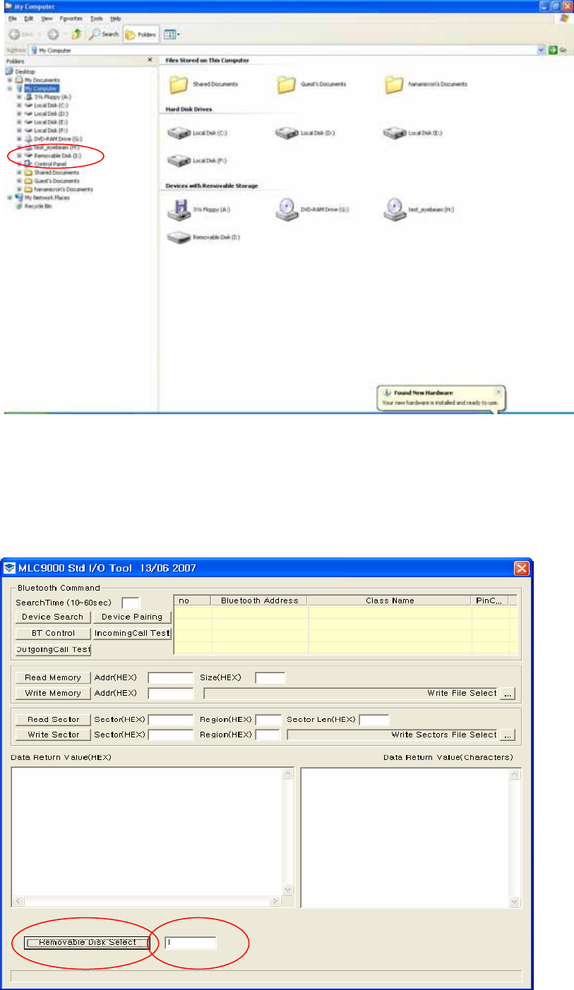
1. Plug the device into the USB port of PC.
2. Check if the device has been successfully installed and connected. And run the StdDTool.exe.
(Make sure that connection is properly working first then, run the StdDTool.exe)
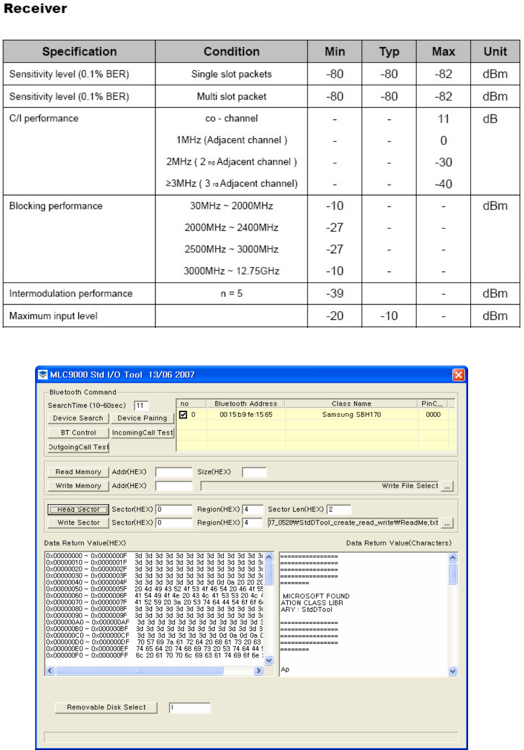
3. Enter the drive letter of the installed removable disk(‘I’” as an example) into the blank at the bottom of the software as following,
then click the ‘Removable Disk Select’ button. Then, this software becomes available to access to the hidden area and also
available to use BT functions.

BT TEST
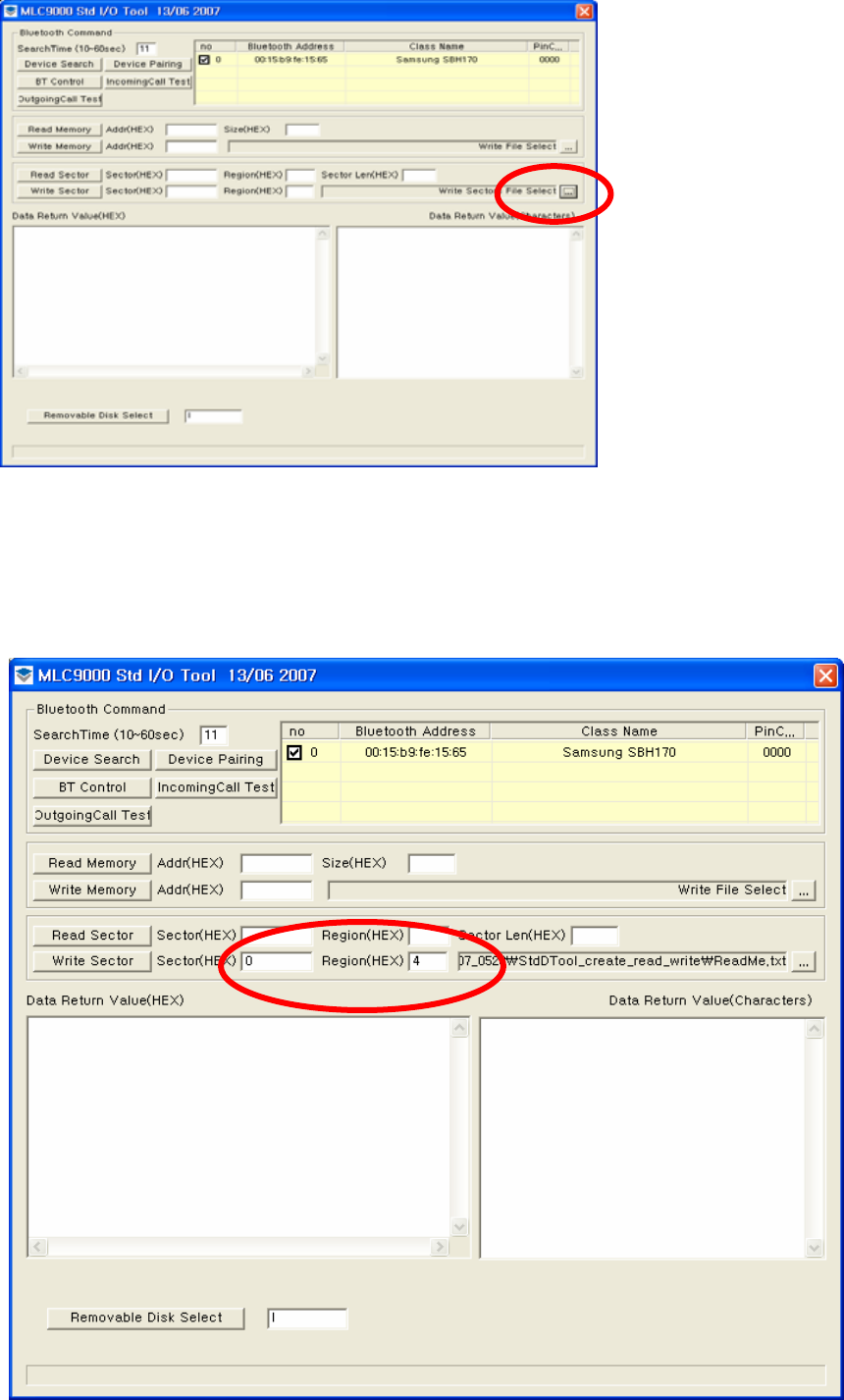
1. Enter the preferred search time (’11 as an example) at the top of the software as following, then click the ‘Device Search’
button.
(Before performing this stage, make sure that the BT headset is set to ‘paring ready’ mode)
2. If a device appear in the right pane, check the device vice which you want to pair, then click the ‘Device Paring’ Button. Then
‘Paring OK’ pop-up will appear as following picture.
3. Play any audio(music) file like MP3 to test if you can hear any sound.
4. When you are able to listen to sound properly, click ‘incoming call test’ button. At this stage, you will be able to make voice call
tests. (When clicking the ‘incoming call test button’, you will found that the quality of the sound becomes a little worse. This
happens because the BT profile mode is changed from Stereo Audi’ to Mono Headset. - ** Note: This version doesn’t support
Mono headsets directly yet’)
5. You can also test with ‘recorder’ in the Windows or can control the volumes in the control panel if it’s not loud enough.
Hidden Area TEST
1. Perform the ‘Preparation’ stage as mentioned above.
2. Click the ‘File Select’ button on reselect the file to write in hidden area.
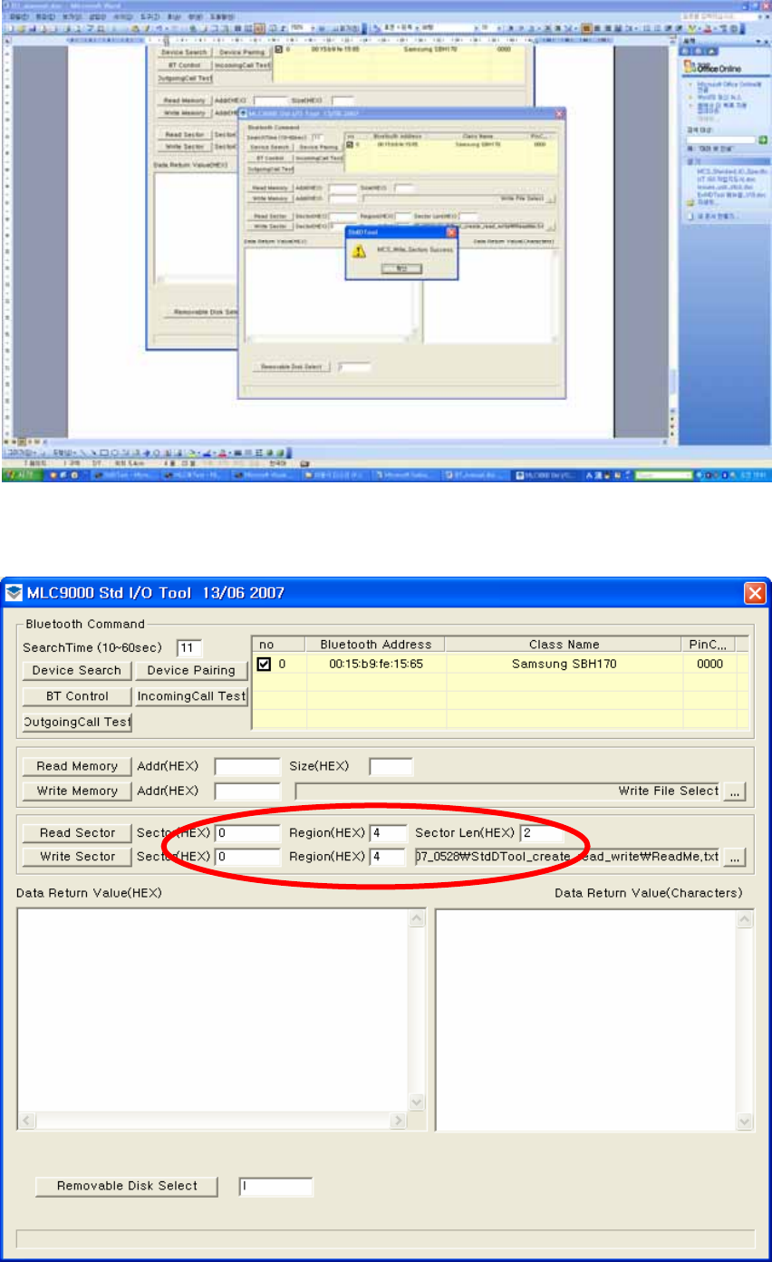
3. Select a Sector (‘0’ as an example. Sector=Address)
1 sector is 512 bytes. Basically starts from 1024 bytes.
(Range: 0~ max sector)
Select a Region (‘4’ as an example)
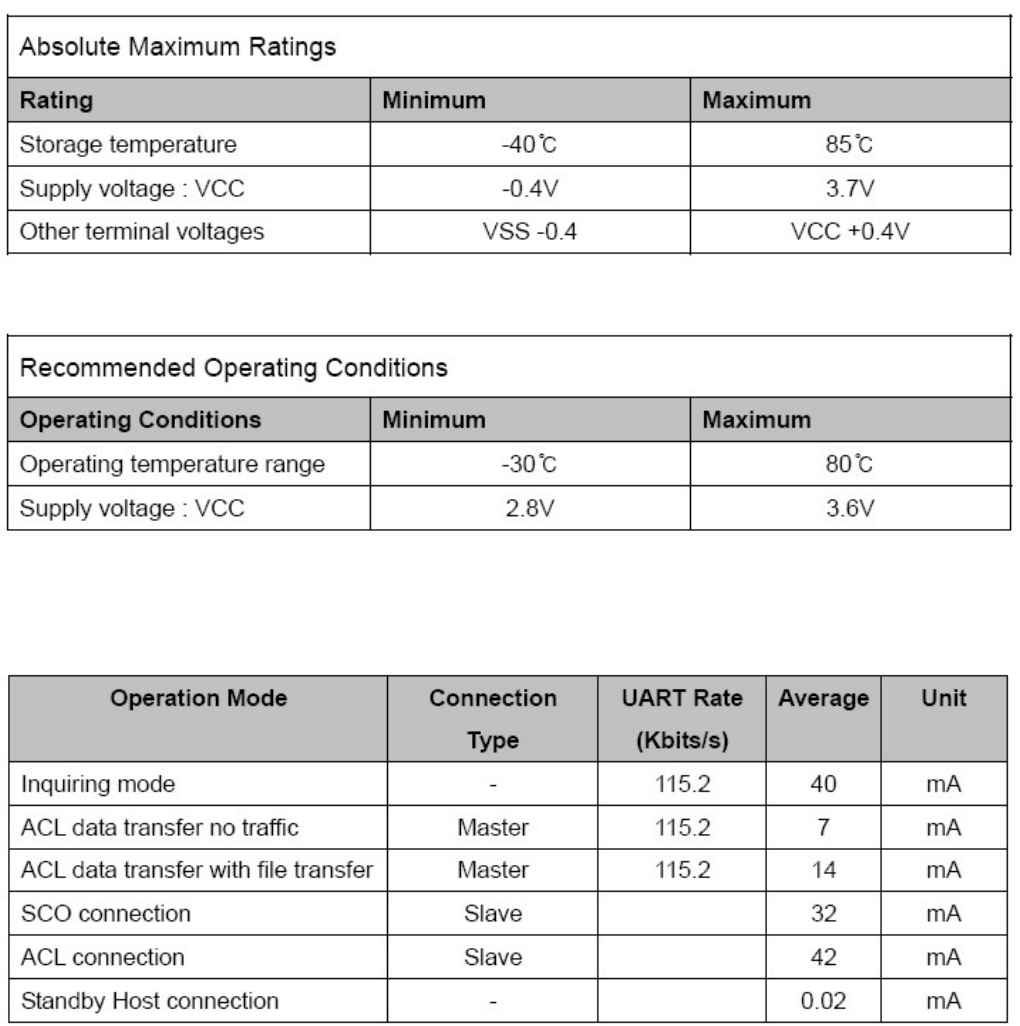
4. Click the ‘Write Sector’ button, then ‘MCS_Write_Sectors Success’ pop-up will appear as following picture.
5. In order to read the hidden area, set the options as followings;

if set the Sector Len to ‘2’, 1024(0x400) bytes will be read.
if set the Sector Len to ‘4’, 2048 (0x800) bytes will be read.
6. Click the ‘Read Sector’ button. (The below is an example when succeeded)

Features
Fully Qualified Bluetooth System
Bluetooth 2.0 Specification Compliant
Kalimba DSP Open Platform Co-Processor
Full Speed Bluetooth Operation with Full Piconet Support
Operating Voltage 2.8~3.6V
UART Interface With programmable baud rate up to 1.5Mbaud
with an optional bypass mode
Full Speed USB v1.1 Interface Supports OHCI And UHCI Host
Interfaces
16-bit Resolution Stereo Audio Codec, Standard Sample Rates
of 8kHz, 11.025kHz, 16kHz, 2.05kHz, 32kHz, 44.1kHz And
48kHz (DAC Only)
Integrated Amplifiers For Driving Microphone And Speakers
With Minimum External Components
Standard HCI (UART and USB) support
Fully Embedded RFCOMM
External 8Mbit Flash Memory
Integrated 26MHz Reference Clock
Competitive Size (9.0mm x 10.0mm x 1.5mm : LGA 44Pin)
Application
Stereo Headphones
Automotive Hands-Free Kits
Echo Cancellation
High Performance Telephony Headsets
A/V Profile Support
Cellular Handsets
Characteristics
Electrical Characteristics
Power Consumption
Note :
Conditions : 25°C, 3.3V supply
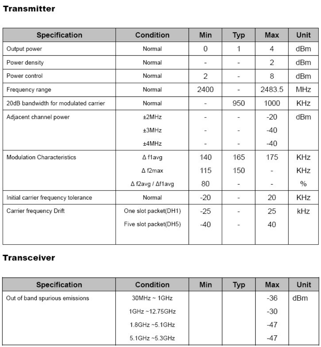
RF Characteristics
FCC Information
This device complies with Part 15 of the FCC Rules.
Operation is subject to the following two conditions: (1) this device may not cause harmful interference, and
(2) this device must accept any interference received, including interference that may cause undesired
operation.
Note:
This equipment has been tested and found to comply with the limits for a class B digital device, pursuant to
Part 15 of the FCC Rules. These limits are designed to provide reasonable protection against harmful
interference in a residential installation. This equipment generates, uses and can radiate radio frequency
energy and if not installed and used in accordance with the instructions, may cause harmful interference to
radio communications. However, there is no guarantee that interference will not occur in a particular
installation. If this equipment does cause harmful interference to radio or television reception, which can be
determined by turning the equipment off and on, the user is encouraged to try to correct the interference by
one or more of the following measures: -Reorient or relocate the receiving antenna -Increase the separation
between the equipment and receiver -Connect the equipment into an outlet on a circuit different from that to
which the receiver is connected -Consult the dealer or an experienced radio/TV technician for help.
CAUTION:
Changes or modifications not expressly approved by the party responsible for compliance could void the
user's authority to operate the equipment.