HANGZHOU ZENO VIDEOPARK IMPORT and EXPORT IPC IPC/Wi-Fi IPC User Manual The Manual of Digital Video Recorder
HANGZHOU ZENO-VIDEOPARK IMPORT & EXPORT CO.,LTD. IPC/Wi-Fi IPC The Manual of Digital Video Recorder
UserManual.wiki
>
HANGZHOU ZENO VIDEOPARK IMPORT and EXPORT
>
IPC User Manual
Users manual
Navigation menu
Upload a User Manual
Namespaces
Wiki Guide
HTML
PDF
Info
Views
User Manual
Discussion / Help
Navigation
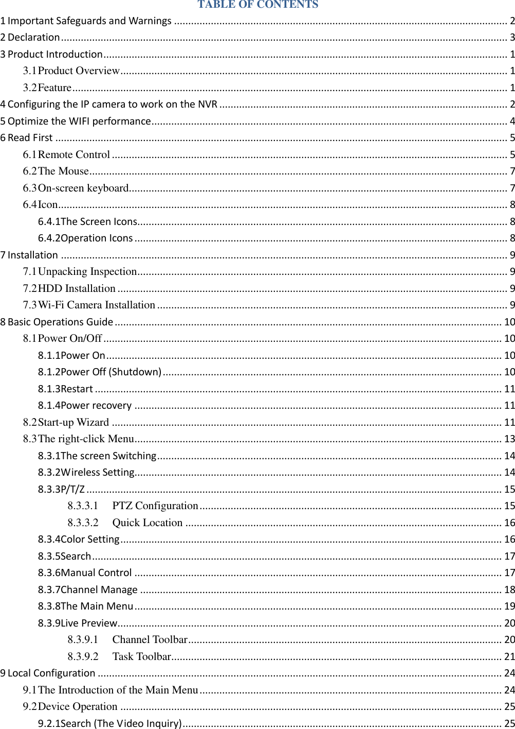
![1) Power on the NVR and WIFI camera, then take the network cable out of the accessories box, and connect camera and NVR via this cable. The light of NVR on the wan port interface should be on, if the light is off, then can’t match code, please check if the cable or device can work well or not. 2) Go to menu [MAIN MENU] > [Wireless Setting], click match button to match code. 3) If match code successfully, the network status will show “OK” and video coming out. Then you can disconnect the network cable.](https://usermanual.wiki/HANGZHOU-ZENO-VIDEOPARK-IMPORT-and-EXPORT/IPC/User-Guide-3953627-Page-9.png)
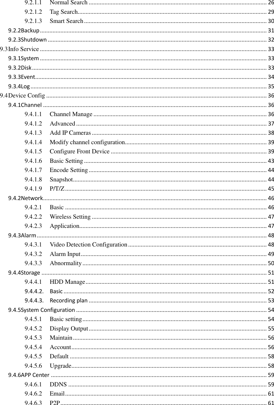
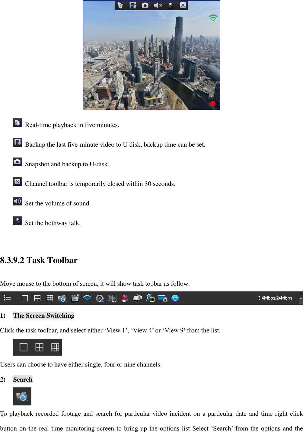
![monitoring area. As far as possible, the installation position of IPC and NVR avoid obstacles (the coverage is affected by the physical properties and surrounding environment of obstacles). 3) To confirm the IPC’s placement: Install the camera in the wireless signal effective coverage area, and provide 12V power. Power on after 1min, the NVR will display the video. If no video, the distance is too far to connect, please shorten the distance. 8 Basic Operations Guide 8.1 Power On/Off 8.1.1 Power On Install the system correctly (as above) and then connect the power, the system will boot automatically. The NVR will then automatically detect any connected hardware (cameras, monitors, etc.), this process should last about 30 seconds. When this process has been completed the NVR will enter the multi-screen real-time surveillance mode. If your hard drive is not properly connected, the following message will appear on your screen. Note:Please do not use any type of power supply which is different from the power supply included in this kit. 8.1.2 Power Off (Shutdown) Right mouse click -[Main Menu]-[Shutdown]](https://usermanual.wiki/HANGZHOU-ZENO-VIDEOPARK-IMPORT-and-EXPORT/IPC/User-Guide-3953627-Page-16.png)
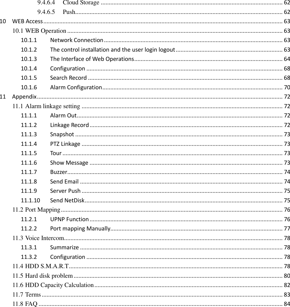
![Note: Only change or attempt to reconnect the hard disk drive after shutting down the NVR. 8.1.3 Restart Right mouse click -[Main Menu]-[Shutdown]-[Restart system] 8.1.4 Power recovery Reboot after an outage or forceful shutdown, DVR will save the record before outage and return to the normal operation mode. 8.2 Start-up Wizard Quick configuration includes System Generic Config, network configuration,etc. System Generic Config System Generic Config includes System Time, DST, Time Zone, NTP enable, Language, Video Standar. [System Time] Set the current time. [Daylight Saving Time (DST)] Enable the function, and enter the local DST starting and ending time. [Time Zone] Current local time in cities worldwide. [NTP] Turn the NTP On/Off. The network time protocol allows the NVR to sync with NTP server time automatically. [Language] Select language. [Video Standard] PAL/NTSC.](https://usermanual.wiki/HANGZHOU-ZENO-VIDEOPARK-IMPORT-and-EXPORT/IPC/User-Guide-3953627-Page-17.png)
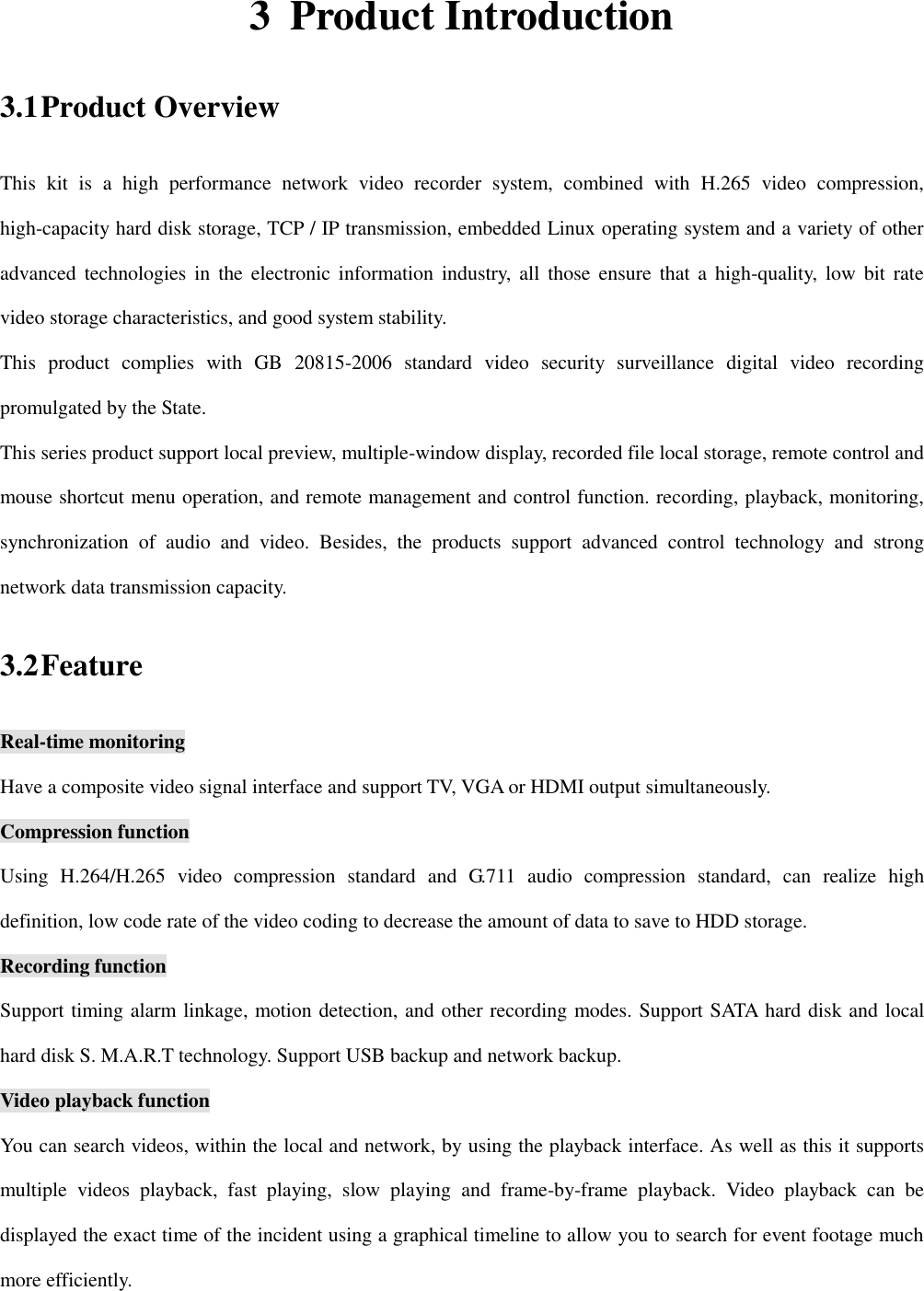
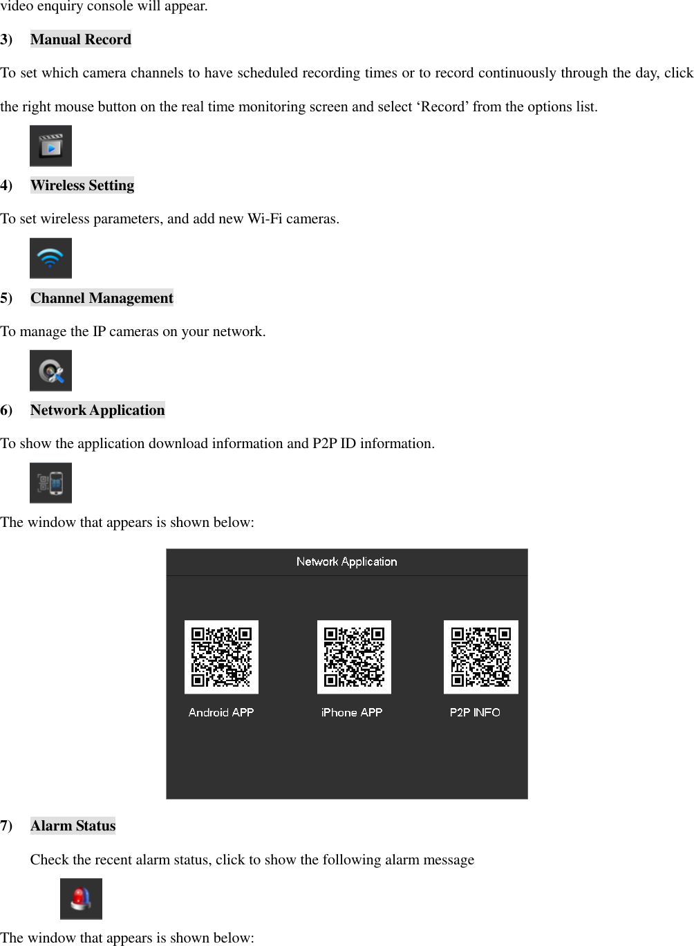
![Network config [DHCP] Enable the NVR to obtain an IP address automatically. If it is enabled, the NVR will reboot and search for a DHCP server, and then assign a dynamic IP address. The dynamic IP address will be displayed in the menu. Enter a static IP address if there is no DHCP service available. If you are using the advanced feature PPPOE, then the IP/mask/gateway and DHCP are unable to be changed. [IP address] Use(▲▼)or input numbers to modify IP, then set [subnet mask] and [gateway] for this IP. [AUTO DNS] Enable the NVR to obtain a DNS address automatically. [DNS 1] DNS server IP address. [DNS 2] DNS alternate IP address. [Test] To test whether the NVR connect internet successfully. Network Application 1) Show the download information, includes P2P WEB, android app and iPhone app.](https://usermanual.wiki/HANGZHOU-ZENO-VIDEOPARK-IMPORT-and-EXPORT/IPC/User-Guide-3953627-Page-18.png)
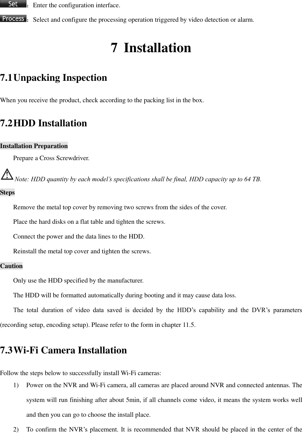
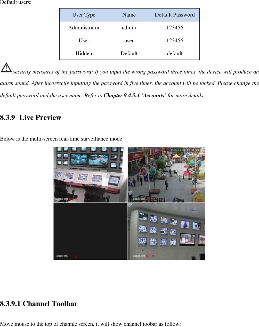
![2) Show the P2P information, scan the QR code by app, then can remote control the NVR. Hard disk management [Format] It is possible to format an individual HDD. Hard disk format operation result in the loss of video data. 8.3 The right-click Menu Enter the real-time channel browsing interface. Click the right button on the mouse to bring up the pop-up menu as shown in the figure below.](https://usermanual.wiki/HANGZHOU-ZENO-VIDEOPARK-IMPORT-and-EXPORT/IPC/User-Guide-3953627-Page-19.png)
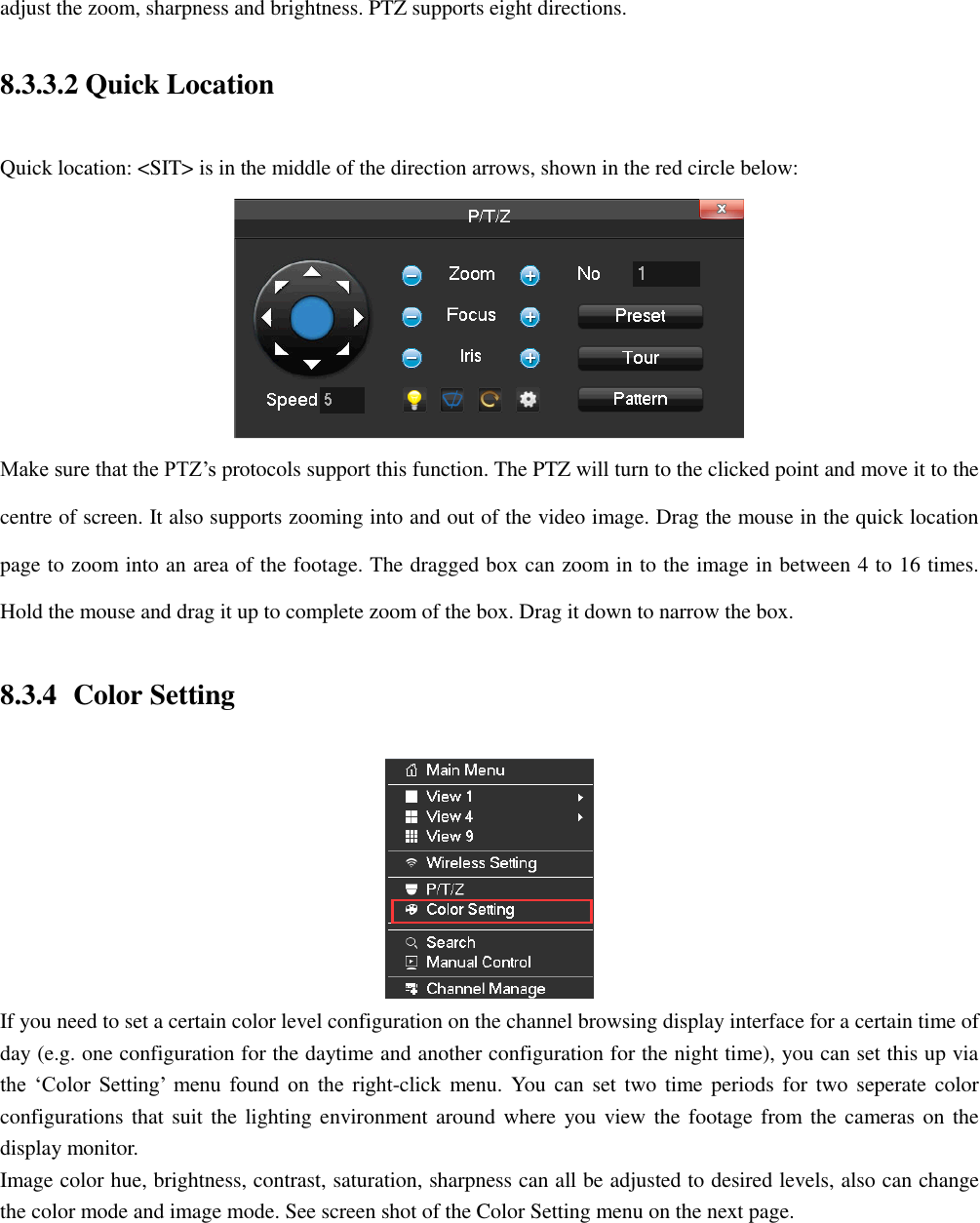
![8.3.3 P/T/Z Click the right mouse button on the real time monitoring screen to bring up the options list, and select ‘P/T/Z’ from the list. When the NVR is connected with a network PTZ camera, right click the corresponding network channel and select [PTZ] to enter into the PTZ interface. The PTZ control interface is shown in the following image: Click to enter the PTZ configuration page: 8.3.3.1 PTZ Configuration The direction of the PTZ camera, steps, zoom, focusing, iris, preset points, cruising between points, patrols, sweeping the boundary, calling an auxiliary switch, light switch, horizontal rotation are controlled using the directional arrow keys. The [Step] is mainly used to control directions. The figure can be set from 1 to 8. Directly click or to](https://usermanual.wiki/HANGZHOU-ZENO-VIDEOPARK-IMPORT-and-EXPORT/IPC/User-Guide-3953627-Page-21.png)
![[Period] Two periods can be set according to ambient light during the day and night, device will automatically switch configuration time. Need to select the Enable box. [Hue] Adjust the image color cast. [Brightness] Visual image brightness (according to the environment), reduces or increases the brightness of the image to try to make it clearer. [Contrast] Adjusts the black and white color the image (the greater the ratio, the brighter the image). [Saturation] Image color purity. The greater the value the more colorful the images will become. [Color Mode] Support Standard mode and Gorgeous mode. [Image Mode] Support Real mode and Transparent mode. Different mode different function. 8.3.5 Search To playback recorded footage and search for particular video incident on a particular date and time right click button on the real time monitoring screen to bring up the options list Select ‘Search’ from the options and the video enquiry console will appear. See Chapter 9.2.1 Search (The Video Inquiry) for further instructions. 8.3.6 Manual Control To set which camera channels to have scheduled recording times or to record continuously through the day, click](https://usermanual.wiki/HANGZHOU-ZENO-VIDEOPARK-IMPORT-and-EXPORT/IPC/User-Guide-3953627-Page-23.png)
![the right mouse button on the real time monitoring screen and select ‘Record’ from the options list. You will see this winodw appear: [Manual] The tick boxes in this row have the highest priority and when you have ticked the corresponding channels the NVR will record continuously. [Schedule] Record footage from the cameras at customized times during the week. [Stop] Stop recording on that channel. 8.3.7 Channel Manage To manage the IP cameras on your network, click the right mouse button on the real time monitoring screen and select ‘Channel Management’ from the options list. The window that appears is shown below:](https://usermanual.wiki/HANGZHOU-ZENO-VIDEOPARK-IMPORT-and-EXPORT/IPC/User-Guide-3953627-Page-24.png)
![[Add] Add the IP Camera(s) into the Net channels, which you have selected. [Delete] Delete the IP cameras you have selected from NET channel list [Protocol] The protocol used by the IP camera(s). [Search] Search for the online IP Camera(s) in the network. [Ping] Input the remote IP address and check the connection status. To setup an IP camera with the NVR please go to Chapter 9.4.1.1 Channel Manage for future instructions. 8.3.8 The Main Menu To go to the Main Menu of the NVR, click the right mouse button on the real time monitoring screen and select ‘Main Menu’ from the options list. Input a user name and a password.](https://usermanual.wiki/HANGZHOU-ZENO-VIDEOPARK-IMPORT-and-EXPORT/IPC/User-Guide-3953627-Page-25.png)
![8) PTZ control Brings up the PTZ control Menu. 9) Event List When the system is face/perimeter analysis status, click to switch show/hide the intelligent window in the right side of real-time monitoring screen. The window that appears is shown below: [Filter] Events filter: Face detection, Line Crossing detection, Instrusion detection, Object abandoned, Object missing, Density alarm, Crossing the fence, Loitering detection, Retrograde detection. Tag the event. 10) Taskbar Config](https://usermanual.wiki/HANGZHOU-ZENO-VIDEOPARK-IMPORT-and-EXPORT/IPC/User-Guide-3953627-Page-29.png)
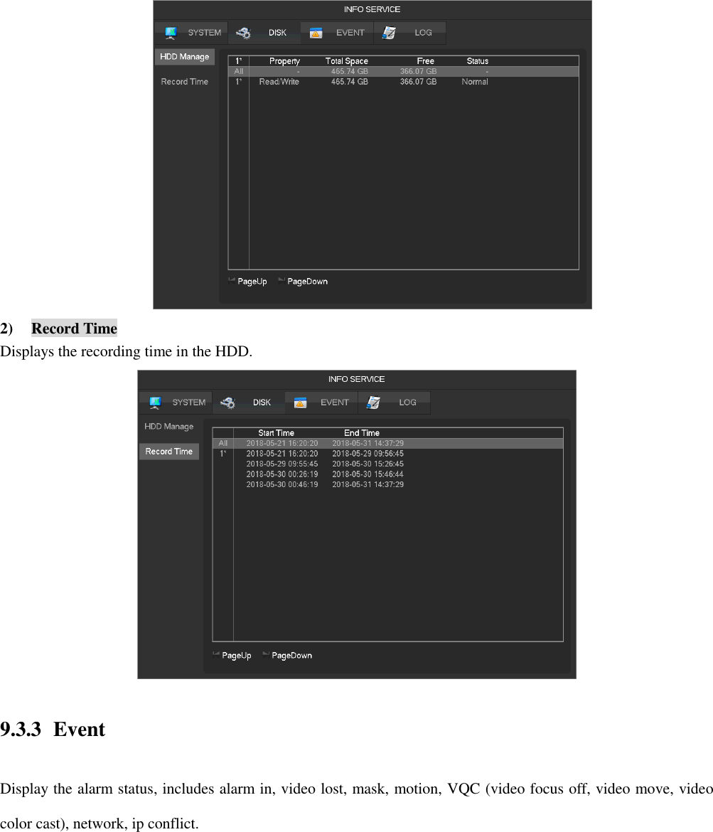
![Chose the taskbar resident or automatically, and display at Bottom or TOP. The window that appears is shown below: 11) Shutdown Menu logout, device shutdown, system reboot. 9 Local Configuration 9.1 The Introduction of the Main Menu The main menu is shown in the image below: 1) DEVICE OPERATION [Search] Search recorded footage by types, channels, time and playback records. [Backup] Backup records. [Shut Down] Takes you to the Shutdown menu. 2) INFO SERVICE](https://usermanual.wiki/HANGZHOU-ZENO-VIDEOPARK-IMPORT-and-EXPORT/IPC/User-Guide-3953627-Page-30.png)
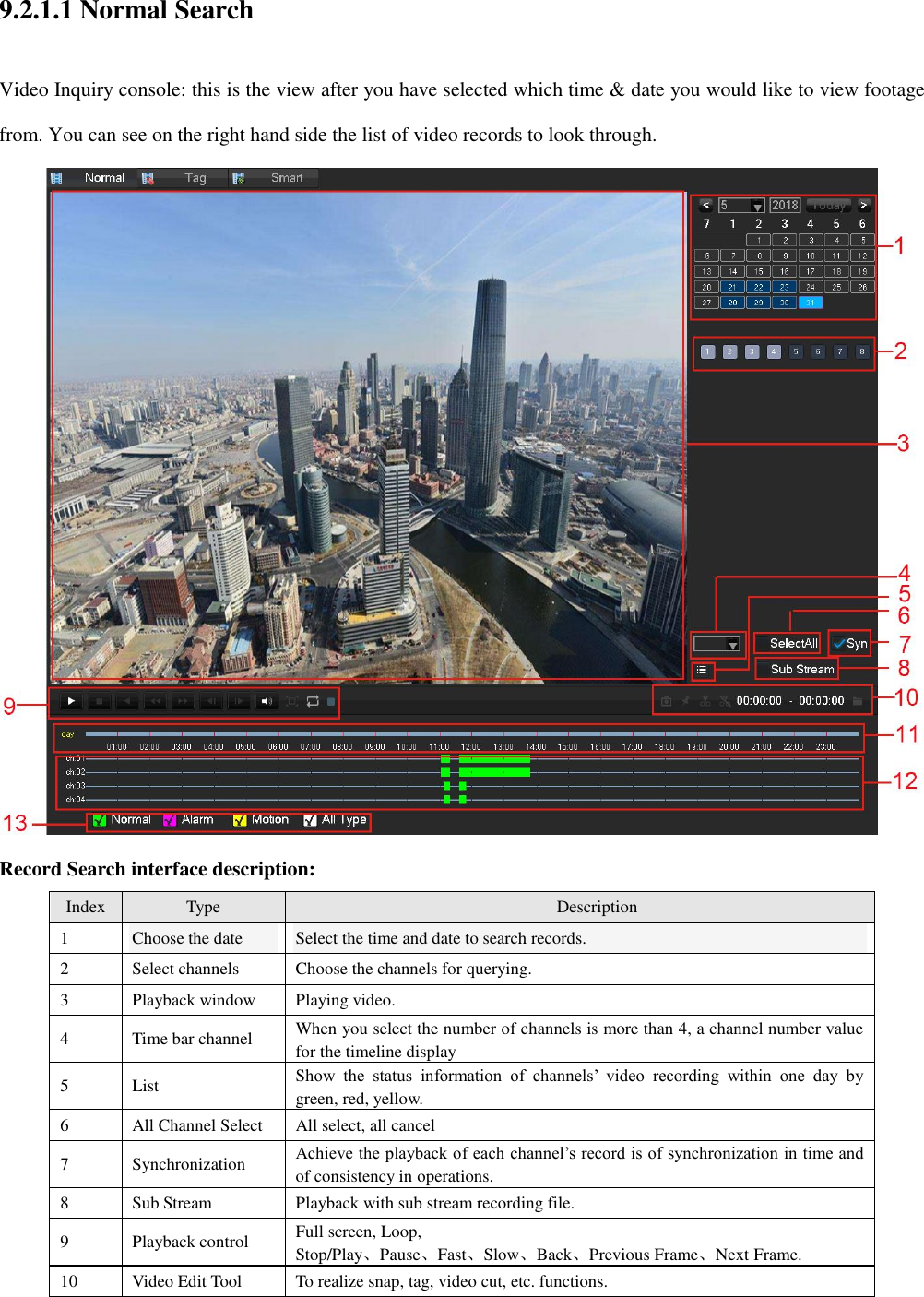
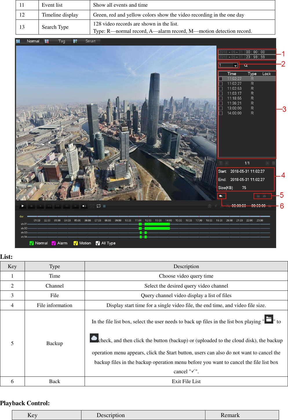
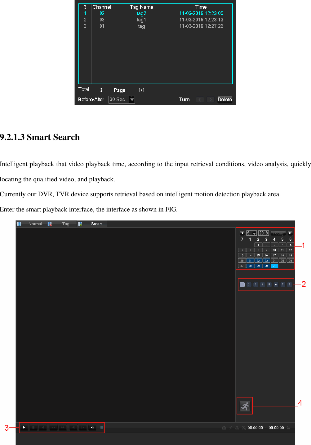
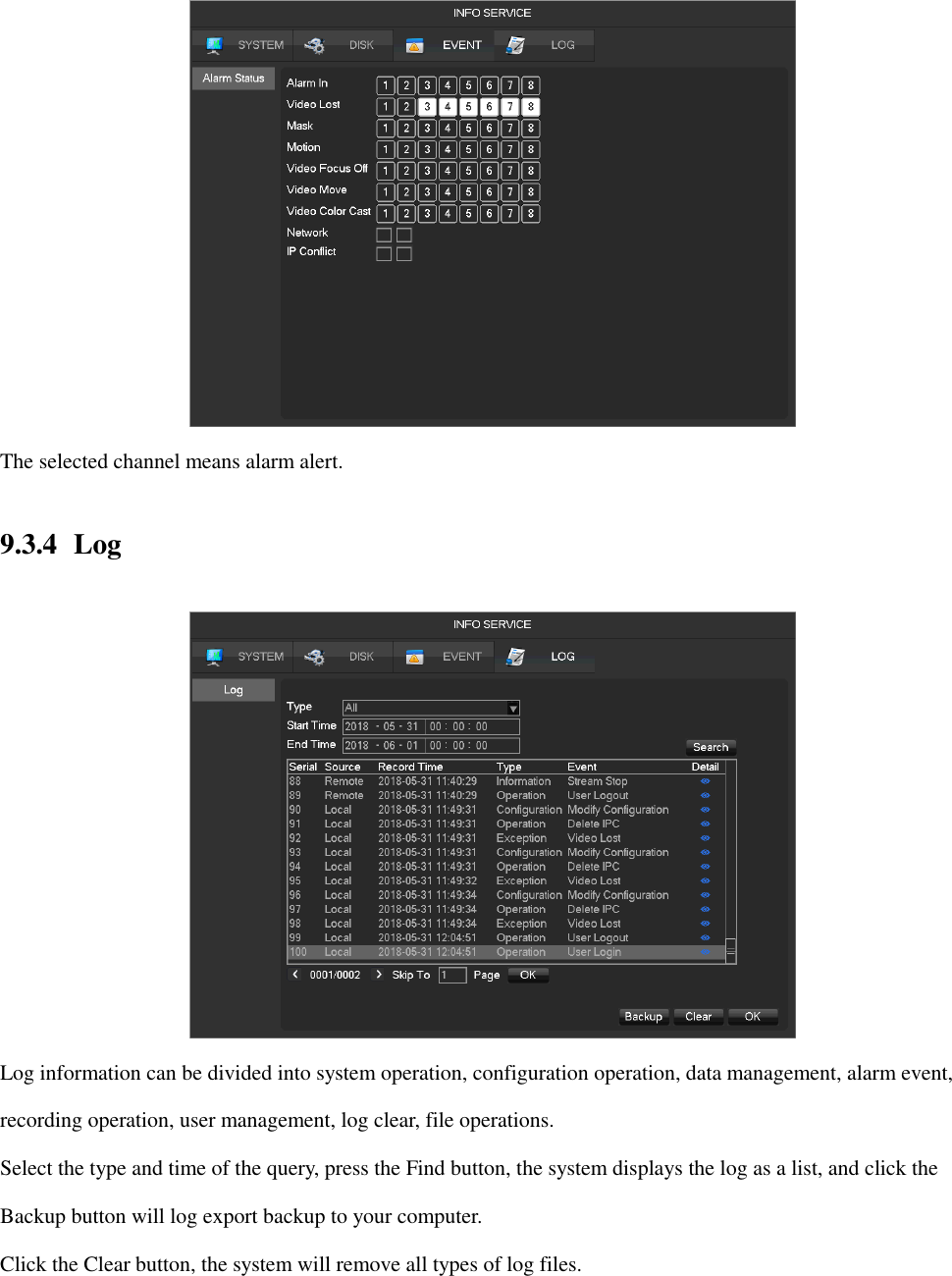
![[System] Displays the system status, version information. [Disk] Displays the HDD information. [Event] Display the alarm information. [Log] System log information. 3) Device Config [Channel] Add / Remove the camera, the camera parameters, the basic parameters of the channel configuration, channel mode switch, channel events and joint management parameters. [Network] Basic network configuration parameters settings, manage network interfaces, configure advanced network services. [Alarm] External alarm events and abnormal events of the configuration parameters of the device and joint management. [Storage] Hard disk storage configuration management, video parameter settings, set the record schedule. [System] Configuration System parameters time, date, language configuration, management and video output parameters polling settings. [APP]E-mail, P2P, cloud storage, mobile phones and other common functions push settings. 9.2 Device Operation 9.2.1 Search (The Video Inquiry) You can access the Video Inquiry either right clicking the mouse button In the real-time monitoring screen and selecting [search] or you can select the ‘Search’ option in the main menu.](https://usermanual.wiki/HANGZHOU-ZENO-VIDEOPARK-IMPORT-and-EXPORT/IPC/User-Guide-3953627-Page-31.png)
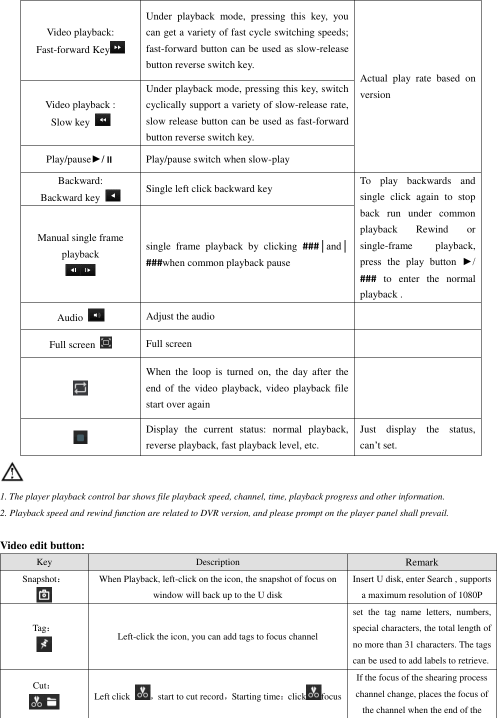
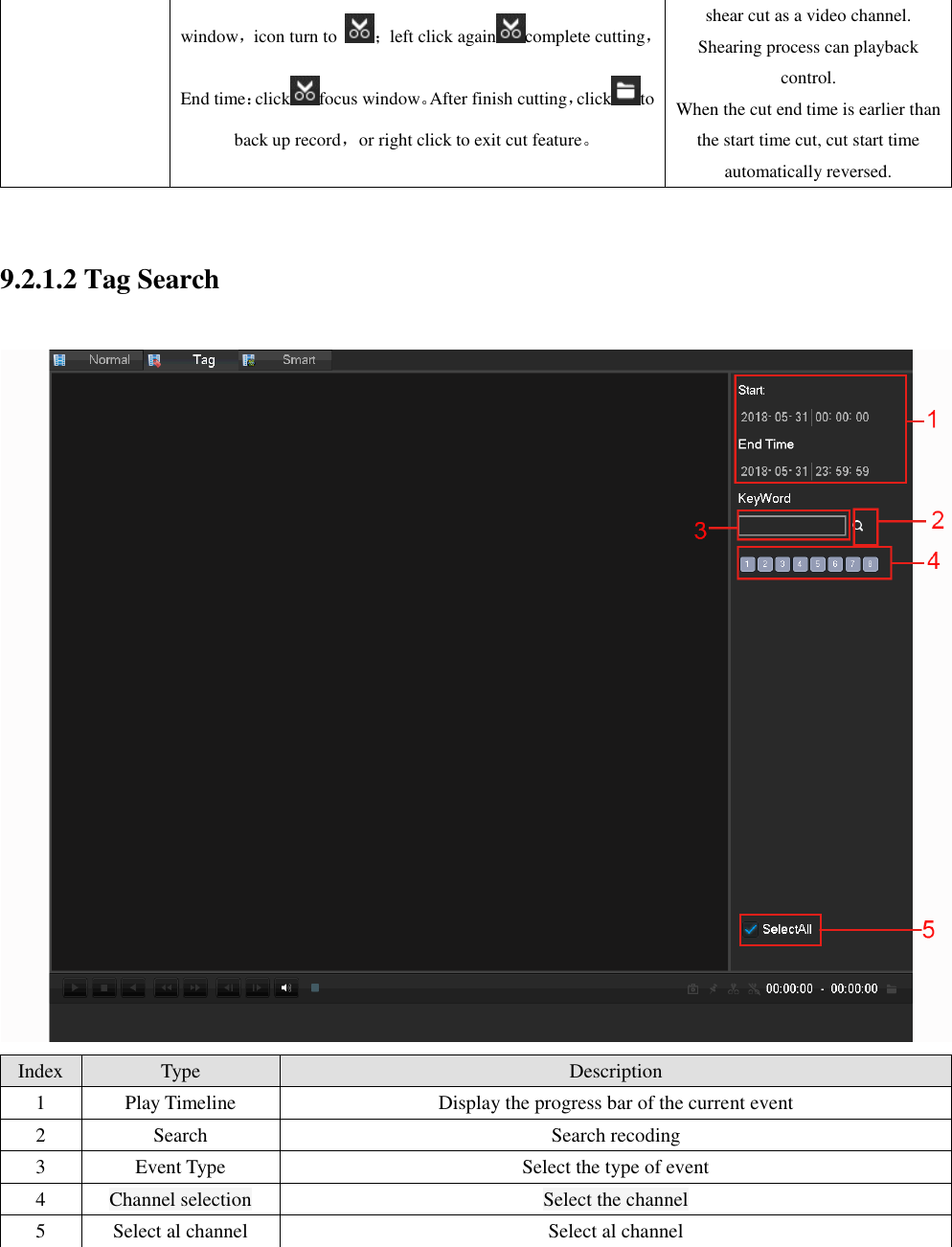
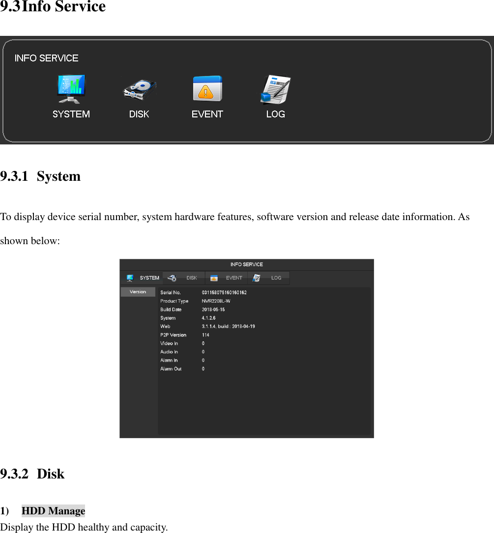
![Intelligent playback using the following process 1. Position 1, select the desired search date. 2. Position 2, select the desired search channel (radio). 3. Left-click on the third position to start playback. 4. Left-click on the icon position 4, select dynamic inspection area. 5. Full-screen setting area is completed, the right mouse button to exit the configuration. Complete search, video recording shall be the date the presence of all the moving subject information of the channel region is configured to display on the timeline. 9.2.2 Backup 1) Interface Description Connect an External USB device with the USB port to backup file in the [Record Backup] menu. [Detect] Identify external USB device and display the device information. [Backup] Tick the external device and click [Backup] to enter the backup menu .](https://usermanual.wiki/HANGZHOU-ZENO-VIDEOPARK-IMPORT-and-EXPORT/IPC/User-Guide-3953627-Page-37.png)
![[Cancel] Delete all data in USB backup device 2) Backup Operations Connect an External USB device with the USB port, click [Detect] to Identify external USB device, click [Backup] to enter the backup menu, select the record start -stop time and click to add files in list, click [Start] to backup and display time remaining. USB backup carry player automatically. This operation probably will cause permanent data loss. 9.2.3 Shutdown Takes you to the Shutdown menu.](https://usermanual.wiki/HANGZHOU-ZENO-VIDEOPARK-IMPORT-and-EXPORT/IPC/User-Guide-3953627-Page-38.png)
![9.4 Device Config 9.4.1 Channel 9.4.1.1 Channel Manage You can use channel management to add or delete IP devices and set the front-end configuration. There are three ways to log in [Channel Manage] 1) Living preview,click the button in the task toolbar. 2) Right click the mouse on the living preview, click the button in the right-click menu. 3) [Main Menu]-[Channel]-[Channel Manage]. Channel management menu as the following page: [Check Box] Click the check channel, double click can deselect channel, Click the title bar to achieve selection, double click can deselect all. [Serial Number] Display the network channel number to add equipment serial number. [Add、Delete] Click to delete the current IP camera. Click to add new cameras. [Status] Show the current channel connection status:Connection is normal,ID or Password is wrong,the equipment is offline,User is lock。 [IP Address/Domain Name] Display the equipment’s IP address/domain name. [Edit] Configure the channel information,see Chapter 9.4.1.3 Modify channel configuration for further instructions.](https://usermanual.wiki/HANGZHOU-ZENO-VIDEOPARK-IMPORT-and-EXPORT/IPC/User-Guide-3953627-Page-42.png)
![ [Advanced] Configure the camera’s parameters, see Chapter 9.4.1.2 Advanced for further instructions. 9.4.1.2 Advanced Click the advanced setting button, will show the Advanced Setting menu. The front-end device has been added into IP channel: [Front Set] See 9.4.1.5 Configure Front Device for further instructions. [Automatic Detection] Check connection status of the current channel. [ShortCut PING] Check the current channel network whether is connected. [Alarm Output] Set the front-end device alarm output mode. [Channel exchange] Exchange position of channels. [Upgrade] Upgrade the Wi-Fi camera. The front-end device has not been added into IP channel: [ShortCut PING] Check the current equipment whether is connected. [Add To] Add device into the special channel.](https://usermanual.wiki/HANGZHOU-ZENO-VIDEOPARK-IMPORT-and-EXPORT/IPC/User-Guide-3953627-Page-43.png)
![9.4.1.3 Add IP Cameras There are three ways to add IPCs. 1) Automatically Add No configuration, the device is automatically added. Click [Open UPNP] in [Channel Management] menu page. Note:The device should support UPNP and should be in the same LAN. 2) Searching Add Search all the IPCs in the network environment and then choose one or mass to add. To do the following steps in [Channel Management] menu page: Click [Filter] to select the protocol; Click [Search] to search devices; Click + to add device or Right click [Add to] to choose the channel you want or tick the devices you want to add, then click [Group Add]. Need to update the password by manually after connecting the camera. 3) Manual Add [Channels] Choose one channel. [Protocol] Choose protocol supported by the device. [IP/ Domain Name] Input front device IP address or domain name. [Port] Input front device TCP port.](https://usermanual.wiki/HANGZHOU-ZENO-VIDEOPARK-IMPORT-and-EXPORT/IPC/User-Guide-3953627-Page-44.png)
![[Username] Input front device username. [Password] Input front device password. [Remote Detect]After completing the above settings, click detect button to check connection status. [Remote Channel]When the front device includes multiple channels, choose one channel for it. Click “App” button to finish. 9.4.1.4 Modify channel configuration 1) Click “Edit” button in the Channel list. 2) Modify the information table, the table details as follow: 9.4.1.5 Configure Front Device Modify the IPC’s Basic configuration, encoding configuration, snapshot, network and motion detection in NVR. Click “Front Setting” button of device in [Channel Management] –[Advance] menu. 1) Basic](https://usermanual.wiki/HANGZHOU-ZENO-VIDEOPARK-IMPORT-and-EXPORT/IPC/User-Guide-3953627-Page-45.png)
![[Channel Choose] Choose a channel. [IP Channel Name] Modify current channel name. [IPC Current Time] Set IPC time. [Time Zone] Set time zone. [Time Sync] Enable IPC time sync with NVR. [IPC Control] Click the prompt whether restart the IPC,[OK]Restart the IPC,[Cancel]Return. 2) Encoding [Channels Choose] Choose one channel. [Audio coding] Select the current audio encoding [Code Level] H.264/H.265 [Resolution] Choose main resolution and sub resolution. [Frame Rate] 1~20FPS [Bit Rate Control] Choose CBR or VBR. When choose CBR, bit rate can be set. When choose VBR, image quality can be set.](https://usermanual.wiki/HANGZHOU-ZENO-VIDEOPARK-IMPORT-and-EXPORT/IPC/User-Guide-3953627-Page-46.png)
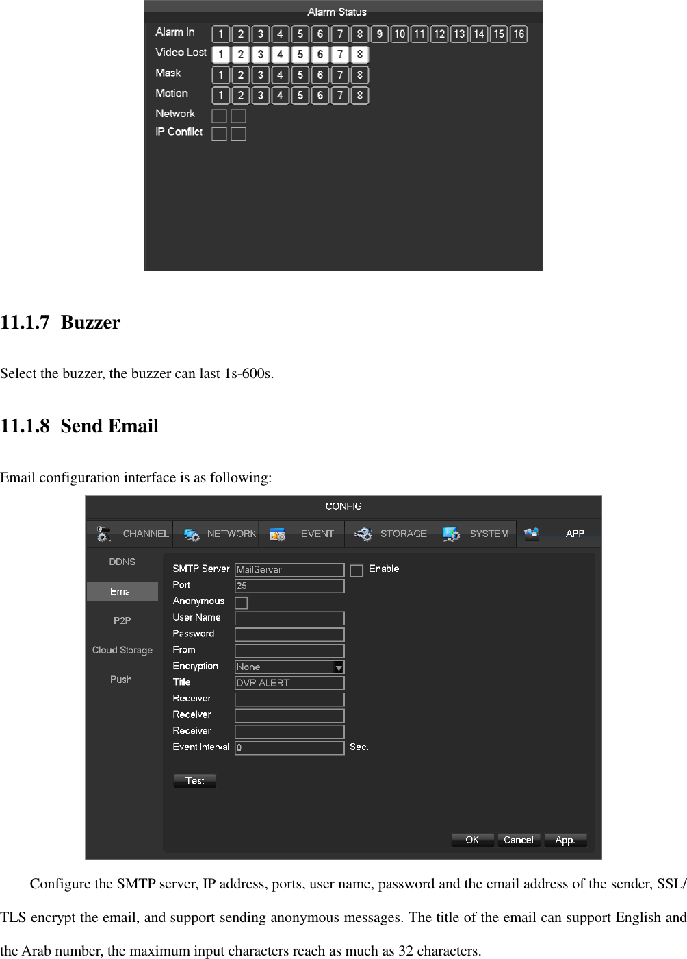
![[Picture Quality] Choose the picture quality by the Variable stream,there are 6 range to choose. [I frame interval] Set interval of adjacent frames. Max is 150. [Bit Rate] Choose 1280,1536,1792,2048,3072,4096,5120,6144,7168,8192 or set by yourself. The range of resolution and frame rate subject to the actual device. 3) Snapshot [Choose Channel] Choose the channel to be modified. [Snapshot Mode] Support two modes: trigger snapshot and timing snapshot, the timing snapshot must tick the checkbox. [Picture Resolution] Set the captured picture resolution. [Image Quality]Choose the picture quality,there are 6 range to choose. [Snapshot Frequency] Support 1sec./pcs.~8sec./pcs 8 ranges of snapshot to choose. 4) Network Wi-Fi camera supports both Wi-Fi network and LAN network, this page is for Wi-Fi. [Channels Choose] Choose one channel.](https://usermanual.wiki/HANGZHOU-ZENO-VIDEOPARK-IMPORT-and-EXPORT/IPC/User-Guide-3953627-Page-47.png)
![[DHCP] Automatic get the IP address. [IP Version] Choose the internet protocol version, IPV4 /IPV6. [IP Address][Subnet Mask][Gateway] Set IP address, subnet mark and gateway for the device. [First DNS Server] Set DNS server IP address. [Alternate DNS Server] Set standby DNS server IP address. [MAC/Serial] Show MAC address of front device. 5) Detection [Channels Choose] Choose one channel. [Motion Enable] Enable the motion detection alarm or not. [Dejitter] Only record one alarm event in this time, the default is 5sec. [Set Area] Set the motion detection area. There are 396 (22*18) regions can be set. There are 6 sensitivity levels for motion detection.](https://usermanual.wiki/HANGZHOU-ZENO-VIDEOPARK-IMPORT-and-EXPORT/IPC/User-Guide-3953627-Page-48.png)
![The network protocol selected when connecting the IPC must supporting to configurate this feature. All the settings are for front device. [Blind Enable] Enable the blind detection alarm or not. 6) Account To get the IPC’s account list. If the current account is administrator will get the whole account list, or can’t get the other accounts information. 9.4.1.6 Basic Setting [Channel] Select the desired channel. [Channel name] Select the channel name. [Channel display] Set the position of the channel title. [Time display] The position of the time title on the screen.](https://usermanual.wiki/HANGZHOU-ZENO-VIDEOPARK-IMPORT-and-EXPORT/IPC/User-Guide-3953627-Page-49.png)
![[Time Synchronization] Time synchronization of network channels and the device. [Custom Title] Customized title and location. [Video cover] Set protected area of previewing and recording. 9.4.1.7 Encode Setting [Channel] Select the desired channel. [Compression] H.264 / H.265. [Resolution] The resolution of main stream and sub stream. Different channels correspond to different resolutions. Frame rate setting range is also different. [Frame Rate] 1fps-20fps. Resolution and frame rate are vary depending on NVR model. [Bitrate Control] Constant Bit rate or Variable Bitrates. Bit rate can be set as Constant Bit Rate (CBR). There are 6 levels for image quality in Variable Bit Rate (VBR), 6 is the best but it has to be fixed to Constant Bit Rate when selected. 9.4.1.8 Snapshot Store an image snapshot from the camera(s) when the alarm has been triggered.](https://usermanual.wiki/HANGZHOU-ZENO-VIDEOPARK-IMPORT-and-EXPORT/IPC/User-Guide-3953627-Page-50.png)
![[Channel] Select a channel. [Mode] Trigger: When this option is set the NVR with capture an image snapshot as the alarm gets triggered. [Image size] Choose different resolution for snapshot. [Image Quality] There are 6 levels of quality. [Snapshot frequency]set highest capture rate for single channel, 1/2/3/4/5/6/7/8 s/pc. 9.4.1.9 P/T/Z [Channel] Select the PTZ channel to set. [Control Type] NET, based on the channel type. [Protocol] Select the PTZ protocol (e.g.Net Protocol). [Address] The PTZ’s address. [Baudrate] The PTZ’s baudrate, can find it in the PTZ OSD, the default is 9600.](https://usermanual.wiki/HANGZHOU-ZENO-VIDEOPARK-IMPORT-and-EXPORT/IPC/User-Guide-3953627-Page-51.png)
![[Data Bits] Default is 8. [Stop Bits] Default is 1. [Parity] Default is none. [DVR Control] Enable it can virtual the PTZ features. [Frequency] Default is 3sec. The value range is 1~30secs. 9.4.2 Network This menu section allows you to configure the network settings of the NVR. It is recommended that an experienced network technician should only be able to configure settings in this menu section. 9.4.2.1 Basic [DHCP] Enable the NVR to obtain an IP address automatically. If it is enabled, the NVR will reboot and search for a DHCP server, and then assign a dynamic IP address. The dynamic IP address will be displayed in the menu. Enter a static IP address if there is no DHCP service available. If you are using the advanced feature PPPOE, then the IP/mask/gateway and DHCP are unable to be changed. [IP Address] Use () or input numbers to modify IP, then set [mask] and [gateway] for this IP. [AUTO DNS] Get the DNS from the DNS server automatically. [First DNS Server] DNS server IP address. [Alternate DNS Server] DNS alternate IP address. [Physical Address] Physical address of current net port. [HTTP Port]/[TCP Port] Most is used for net connection.](https://usermanual.wiki/HANGZHOU-ZENO-VIDEOPARK-IMPORT-and-EXPORT/IPC/User-Guide-3953627-Page-52.png)
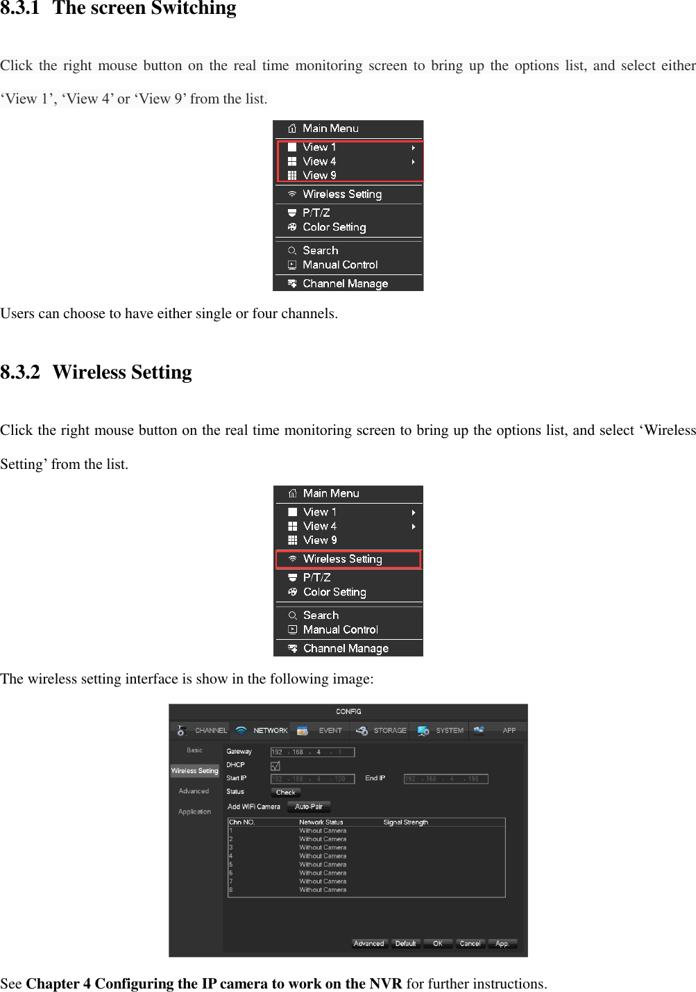
![9.4.2.2 Wireless Setting [Gateway] Wi-Fi gateway, default is 192.168.4.1, you can change the segment. [DHCP] Enable the DHCP, then will assign IP address to Wi-Fi camera automatically. [Start IP]/[End IP] The IP address pool which Wi-Fi cameras can use. [Status] Wireless channels healthy. [Add WiFi Camera] Add new Wi-Fi camera into the kit, see Chapter 4 Configuring the IP camera to work on the NVR for further instructions. 9.4.2.3 Application [NTP]Select Enable switch to turn on the NTP protocol support, can be with SNTP communication server to realize automatic calibration function.](https://usermanual.wiki/HANGZHOU-ZENO-VIDEOPARK-IMPORT-and-EXPORT/IPC/User-Guide-3953627-Page-53.png)
![ [Host IP] Enter the IP of NTP service NTP, default is windows NTP server. [Port] Supports TCP transport only, port is limited only 123. [Update Period] Interval time is 1 minute or more, the maximum update period is set to 65,535 minutes. [IP Permissions] For permission to access the DVR IP rights management. When choosing the white list, the list indicates that only the IP to connect this DVR. Up to 64 IPs. If the selected item is not ticked, no restrictions on accessing to the device's IP. 9.4.3 Alarm Support video detect, external alarm detect, and abnormality alarm. 9.4.3.1 Video Detection Configuration The video detection includes motion detection, video lost, video blind and VQD (video quality detectio).](https://usermanual.wiki/HANGZHOU-ZENO-VIDEOPARK-IMPORT-and-EXPORT/IPC/User-Guide-3953627-Page-54.png)
![[Channel] Select a channel. [Alarm Type] Motion detection, video lost, video blind and VQD. [Motion Detection] Detect the motion in the picture, and send alarm according to setting. [Video Lost] Detect the video loss and send alarm according to setting. [Video Blind] Detect the video which was covered and send alarm according to setting. [VQD] Analysis the video quality, if virtual, camera move or color cast, then will alarm based on the alarm plan. [Anti-Dither] Will only alarm one time during this time, the default is 5sec. [Enable] Enable the alarm or not. [Set Area] There are totally 22*18=396 area can be set, support 4 kinds of sensitivity. [Sensitivity] Highest, higher, middle, low, lower, lowest. [Working Period] Set the alarming schedule. [Linkage Config] Set the alarm linkage and the handling method. [Preferences End] It will show a test on the current setting. [Copy] Copy the setting to other channels. 9.4.3.2 Alarm Input Alarm come from IP cameras.](https://usermanual.wiki/HANGZHOU-ZENO-VIDEOPARK-IMPORT-and-EXPORT/IPC/User-Guide-3953627-Page-55.png)
![[Alarm Input Channel No] Select a channel. [Enable] Control the open and close of alarm. [Type] Choose Normal open and Normal close. [Working Period] Set the alarming schedule. [Linkage Config] Set the alarm linkage and the handling method. [Anti-Dither] Will only alarm one time during this time, the default is 1sec. [Front-end alarm Channel] If IP camera supports more than 1 alarm in, then should choose which for this net channel. [Copy] Copy the setting to other channels. 9.4.3.3 Abnormality Provide multiple equipment abnormal monitoring function, and it can do the corresponding alarm linkage of equipment abnormal events. [Main Menu]-[Alarm]-[Abnormality] Enter the configuration interface as shown in the figure below:](https://usermanual.wiki/HANGZHOU-ZENO-VIDEOPARK-IMPORT-and-EXPORT/IPC/User-Guide-3953627-Page-56.png)
![[Exception type] [No HDD] Alarm when HDD is not present or cannot be detected. [HDD No Space] Alarm when hard disk capacity is lower than setting. [Off Network Events] Alarm when network is not connected. [IP Conflict] Alarm when IP address conflict. [HDD Error] Alarm when there is error in reading and writing hard disk. [Alarm Output], [linkage record], [snapshot], [Send Email], [show message], [Send to network drive], [buzzer] Regarding linkage setting, see Chapter 11.1 ‘Alarm Linkage Setting’ for future instructions. 9.4.4 Storage 9.4.4.1 HDD Manage Show the HDD space and status.](https://usermanual.wiki/HANGZHOU-ZENO-VIDEOPARK-IMPORT-and-EXPORT/IPC/User-Guide-3953627-Page-57.png)
![Hard disk format operation results in the loss of video data. [Set] Set HDD as read-write, read only or redundancy mode. Video data can be protected from covering under read only mode. It supports HDD S.M.A.R.T smart detection at the same time. 9.4.4.2. Basic](https://usermanual.wiki/HANGZHOU-ZENO-VIDEOPARK-IMPORT-and-EXPORT/IPC/User-Guide-3953627-Page-58.png)
![[Record Mode] Support three modes, ‘record automatically’, ‘manually’ or ‘not record’. [Record Overlay] The range is 0~31. [Video Package Time] The figure is between 5 to 120 minutes. [HDD Full] Overwrite or stop recording. [Sub Record] Sub-stream recording switch. Enable it, then will recording with sub-stream and main stream. [Channel] Select a channel. [Video Redundancy] Open or close the redundant recording. [Pre-recorded]The figure is between 0 to 30 seconds, default is 4 seconds. 9.4.4.3. Recording plan [Channel] Select a channel. Green shows normal recording, Yellow shows motion detection, and Red shows Alarm. Users can set or change setting according to date. [Setting] Select recoding method.](https://usermanual.wiki/HANGZHOU-ZENO-VIDEOPARK-IMPORT-and-EXPORT/IPC/User-Guide-3953627-Page-59.png)
![ [Period] Set the recording period, there will be 6 period to choose. [Regular] Regular recording. [MD] Motion detection recording. [Alarm] Alarm recording. [Copy] Copy the setting to other channels. 9.4.5 System Configuration 9.4.5.1 Basic setting Get into the [Basic] menu under [Device Config] [System Time] Set the HD record system time.](https://usermanual.wiki/HANGZHOU-ZENO-VIDEOPARK-IMPORT-and-EXPORT/IPC/User-Guide-3953627-Page-60.png)
![please click the”save” button to save the time after setting. [Daylight Saving Time (DST)] Enable the function and click “Set” to enter the local DST starting and ending time setting. [Date Format]Modify the date display format. [Date Separator]Select the separator for date. [Time Format] 24 hour or 12 hour display mode. [Time Zone] Select the time zone. [Language] Select language (different models have different language choice). 9.4.5.2 Display Output [Display] HDMI&VGA [Resolution] Select the VGA output resolution and refresh rate. [Enable Tour] Enable switch. [Interval] Tour interval time is 5-120s. [View] It includes single screen, four-, nine-, sixteen-screen. [Motion Tour] Set the motion detection tour mode. [Alarm Tour] Set the alarm tour mode.](https://usermanual.wiki/HANGZHOU-ZENO-VIDEOPARK-IMPORT-and-EXPORT/IPC/User-Guide-3953627-Page-61.png)
![9.4.5.3 Maintain [Auto maintain] Set the desired the project of automatic maintenance. 9.4.5.4 Account [Add User] Increase users within the group and settings user access control. [Modify User] Modify the user and settings user access control. [Add Group] Add group and settings group access control. Enter into the menu interface of Increase the group, determine the group name, select 83 access control, left click mouse button to confirm, save the new user group. [Modify Group] To modify the group attribute which already exists. [Modify Password] To modify password.](https://usermanual.wiki/HANGZHOU-ZENO-VIDEOPARK-IMPORT-and-EXPORT/IPC/User-Guide-3953627-Page-62.png)
![ Select the user,enter old password then enter new password and confirm Click [confirm] button to make sure modify password. The password can be set 1-6. Beginning and ending spaces is invalid password, you can have a space in the middle. Users which has User Account Control permission can change their own passwords, can also modify other users' passwords. The following user names and user group names, etc., character and length consisting up to six bytes, the invalid string is trailing spaces. Legal characters: letters, numbers, underscores, minus sign, point, other characters are not allowed to use. the number of users and groups is not limited,User Group increased or delete according to user-defined::The factory settings are user \ admin two groups. Users can set their own related group, the group of users can be freely re-assign permissions at the group permissions. user management using two methods of user and group,,Group name and the user name cannot be repeated,,each user must belong to a group, a user can belong to only one group. There are three users: admin, user, and hidden default initialization. The factory password for first two are 123456. Admin default user permissions are high at the factory, and the factory default user as a low privileged user, only for monitoring, playback. Hidden default: This user system for internal use and cannot be deleted. When local is in "no user is logged" state, the system will automatically log in with this account. Users can modify this account permission to do what free login can do. Enter to the menu interface of increase user, Enter your user name and password, select belongs to which group, and select whether to reuse this user. Reuse means that the account can be used simultaneously, multiple clients can use the account.。 Once the group belongs selected, the user's permissions only a subset of the group, not ultra vires the properties of the group.](https://usermanual.wiki/HANGZHOU-ZENO-VIDEOPARK-IMPORT-and-EXPORT/IPC/User-Guide-3953627-Page-63.png)
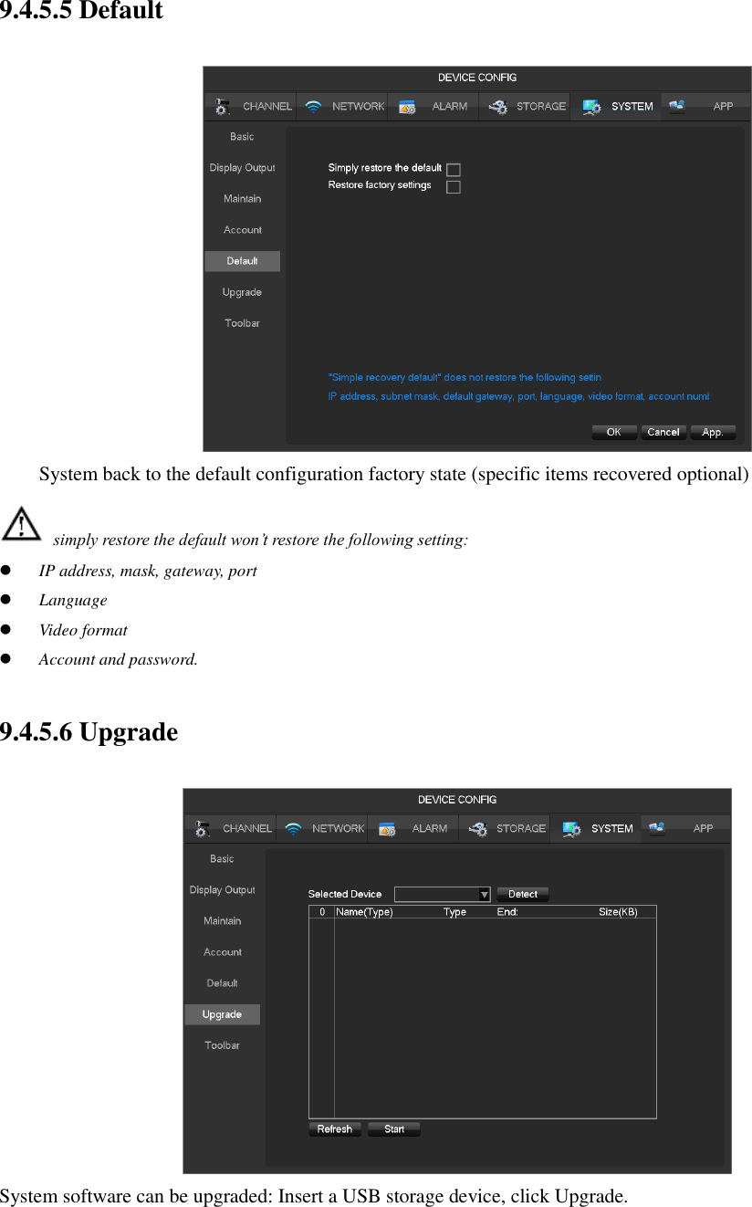
![System upgrade may cause the NVR can not start properly, please Operation under the guidance of the company's technical staff. 9.4.6 APP Center 9.4.6.1 DDNS Dynamic DNS is a kind of system which point internet domain name to variable IP. According to the rule of internet domain name, domain name must associate with the fixed IP address. Dynamic DNS provide a fixed Name server for the dynamic domain, and then guide the domain search to the IP address of dynamic user through Name server, which can make the outside user connect to the dynamic user’s URL. 1) FNT DDNS FNT DDNS is built-in professional dynamic DNS service in our network DVR. You can register directly in the device .Specific steps are as following. [Main menu]-[APP]-[DDNS], choose FNT DDNS. Select FNT DDNS and Enabled it. Input one user name, there will be a domain name generated auto. Domain name = user name.faceaip.net. Input the password Click “Register” button. If the domain name is not registered, it will pop up a message that connect DDNS server successfully otherwise it will prompt that the registration is failed.](https://usermanual.wiki/HANGZHOU-ZENO-VIDEOPARK-IMPORT-and-EXPORT/IPC/User-Guide-3953627-Page-65.png)
![Suggestion: you’d best change the DNS server in basic configuration to the router's DNS server Click the “ok” button to complete the settings. 2) No-IP DDNS Register new account at www.no-ip.com. Embedded NVR Setting: Open [Main Menu]-[APP Centre]-[DDNS], choose NO-IP DDNS. Refer to the following configuration: Name Configuration DDNS type NO-IP DDNS Host IP dynupdate.no-ip.com port 80 Domain name xxx.xxx.org(xxx:domain name created) User name xxx(user name registered) password xxxxxx(password registered) 3) Dyndns DDNS Register new account at www.dyndns.com. Embedded NVR Setting: Open [Main Menu]-[APP Centre]-[DDNS], choose NO-IP DDNS. Refer to the following configuration: Name Configuration DDNS type Dyndns DDNS Host IP Members.dyndns.org port 80 Domain name xxx.xxx.com(xxx:domain name created) User name xxx(user name registered) password xxxxxx(password registered)](https://usermanual.wiki/HANGZHOU-ZENO-VIDEOPARK-IMPORT-and-EXPORT/IPC/User-Guide-3953627-Page-66.png)
![9.4.6.2 Email See Chapter 11.1.8 ‘Send Mail’ for future instructions. 9.4.6.3 P2P [Enable] Open/Close P2P function. [Transfer Mode] Network transfer strategy, choose Quality priority or Fluency priority. [Account Reuse] Enable it supports multiple users log in the same device. [Device ID] Display device ID. [Password] Device password. [Local Port] Set local port. [P2P Server URL] P2P server URL.](https://usermanual.wiki/HANGZHOU-ZENO-VIDEOPARK-IMPORT-and-EXPORT/IPC/User-Guide-3953627-Page-67.png)
![[State] Current connection state. 9.4.6.4 Cloud Storage See Chapter 11.1.10 ‘Send NetDisk’ for future instructions. 9.4.6.5 Push See Chapter 11.1.9 ‘Server Push’ for future instructions.](https://usermanual.wiki/HANGZHOU-ZENO-VIDEOPARK-IMPORT-and-EXPORT/IPC/User-Guide-3953627-Page-68.png)
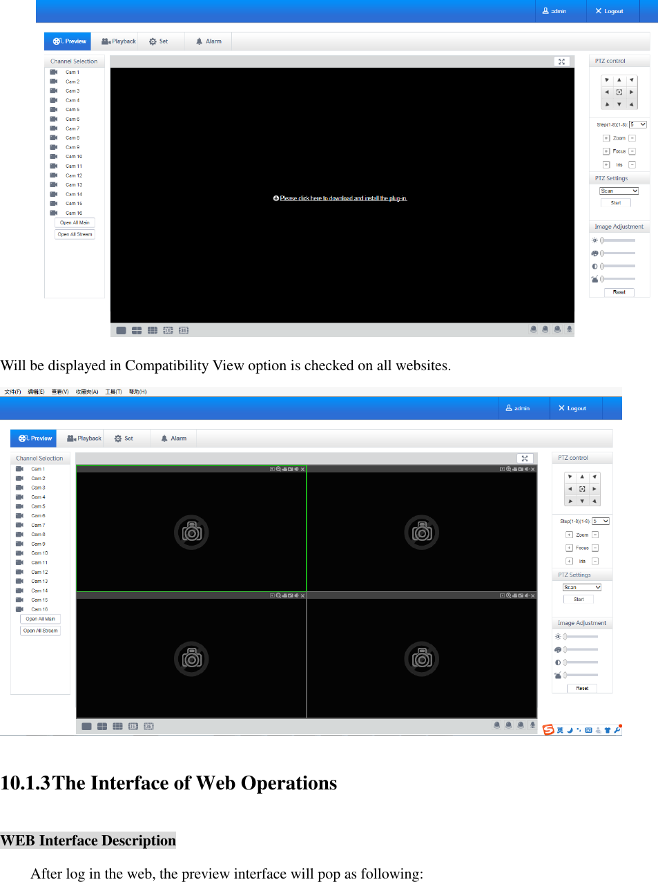
![10 WEB Access 10.1 WEB Operation 10.1.1 Network Connection Check whether the DVR is on the network by checking B-Lamp on front panel, light indicates connection, otherwise connection error. Set IP, subnet mask and gateway for computer and DVR. Please assign the same segment IP address without router, need to set the appropriate subnet mask and gateway with router. The detail of DVR network configuration please see [Configuration]-[Network Setting]. Ensure the IP is correct and check whether the DVR is on the network by using the Windows command “ping”. 10.1.2 The control installation and the user login logout Users can remote access to DVR by Internet Explorer, assuming you have a correct network configuration. The following interface will pop up when you access the IP address in Internet Explorer. The following interface will pop up when you log in.](https://usermanual.wiki/HANGZHOU-ZENO-VIDEOPARK-IMPORT-and-EXPORT/IPC/User-Guide-3953627-Page-69.png)
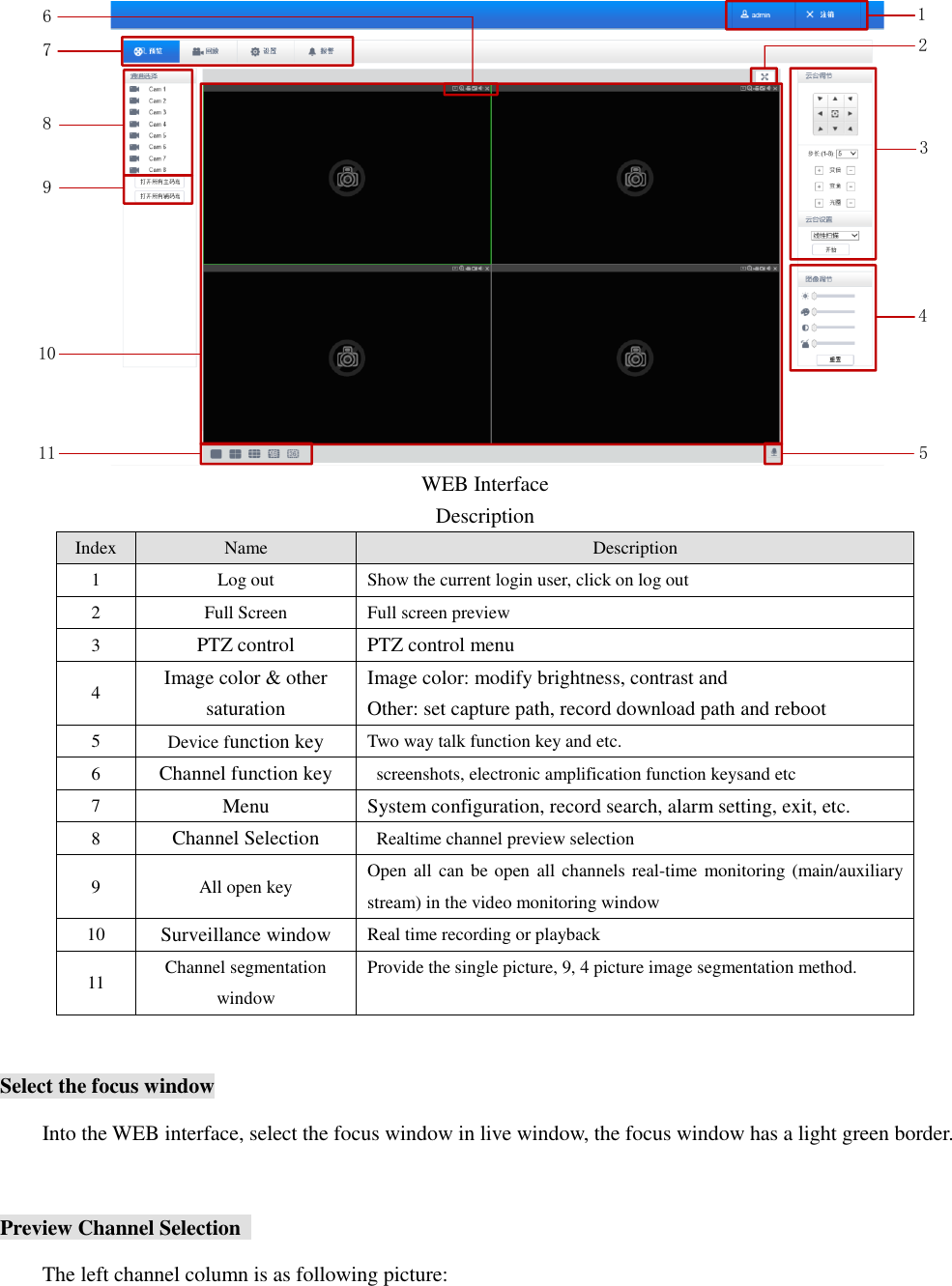
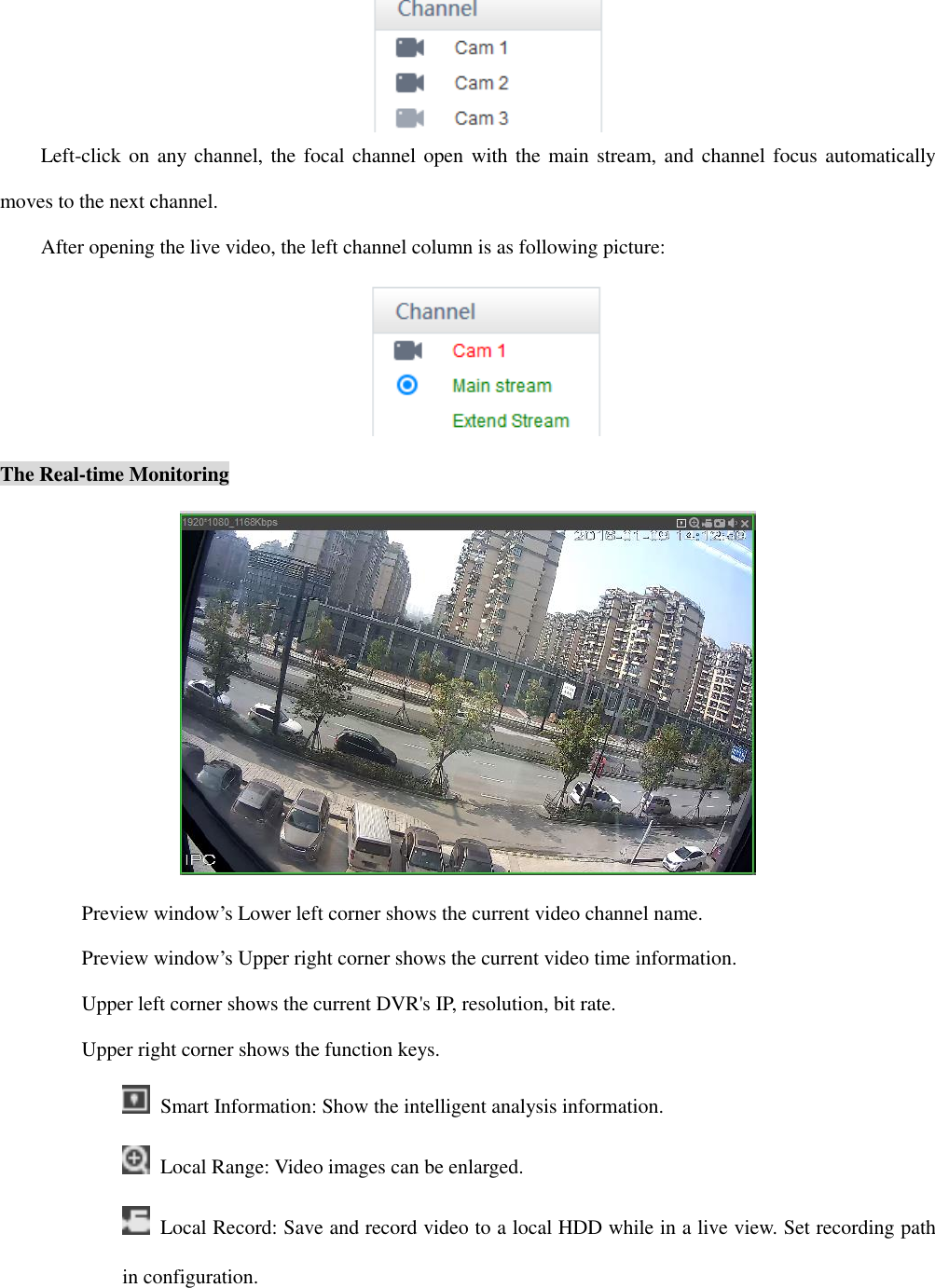
![Capture: capture of the present channel, set the path in “other. Audio: on/off sound. Close video: off the focus window video. Screen split Click “ ”(Lower left corner of the display window)to switch between single screen and multi-screen. PTZ Control Set protocol(see [Setting]-[PTZ]) Control PTZ direction, step size, zoom, IRIS, preset, tour, pattern, border scan, light, wiper, auto pan, etc. Step size controls PTZ direction and speed, e.g. step size 8 is moved faster than step size 1. Eight direction rotations: up, down, right, left, up-left, up-right, lower left, lower right. Border scan Operation: select the camera line scan of the left/right margin by direction button, and click the Settings button in the left /right margin position to determine the left border.](https://usermanual.wiki/HANGZHOU-ZENO-VIDEOPARK-IMPORT-and-EXPORT/IPC/User-Guide-3953627-Page-73.png)
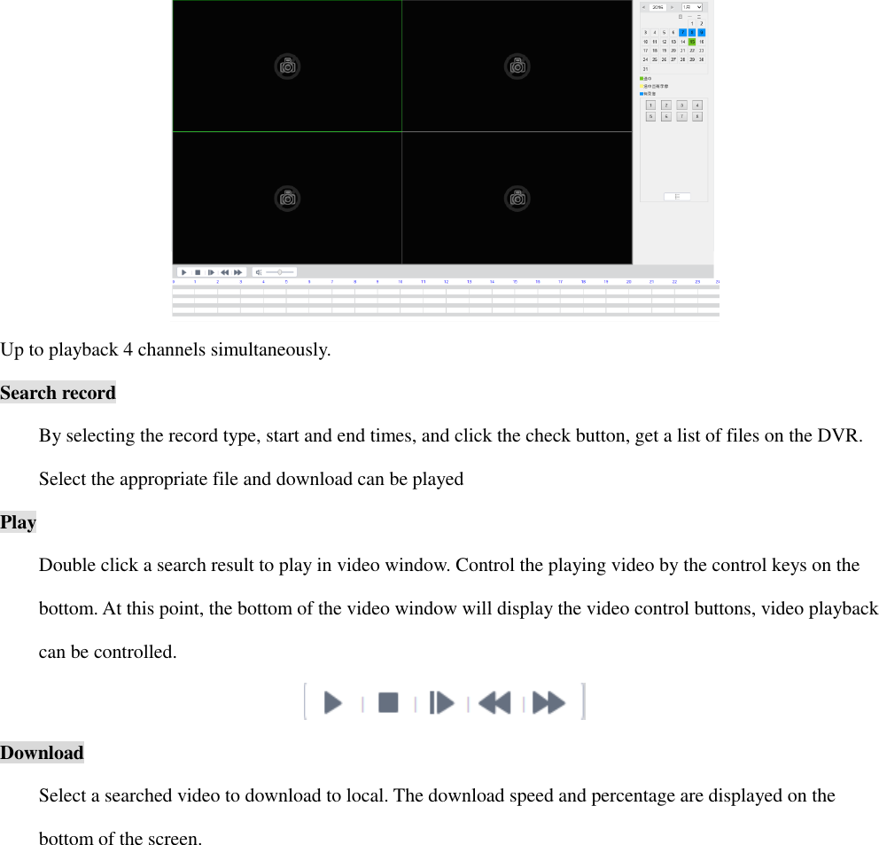
![Preset Operation: modify preset position by direction button and inputting a preset number, then click “Add” to save. Tour Operation: select “Tour”; Point between the first cruise line cruise input box value. And input numbers in “Path” and “preset”. Click[Add Preset]to add one preset in the cruise path, and repeat to add additional presets. Click [Clear Preset]to delete a preset, repeat to delete more. Pattern Operation: Click “Pattern” in order to record an automated pattern. Then, go back to the PTZ controls in order to modify the zoom, focus and IRIS, etc. Stop recording in “Pattern” setting to save the pattern. AUX On/off one of AUX. Wiper On/off wiper under protocol. 10.1.4 Configuration Access DVR local configuration menu by click “System Setting”, the further details please refer. [Local operation guide] 10.1.5 Search Record Click [Playback] to open the search interface:](https://usermanual.wiki/HANGZHOU-ZENO-VIDEOPARK-IMPORT-and-EXPORT/IPC/User-Guide-3953627-Page-74.png)
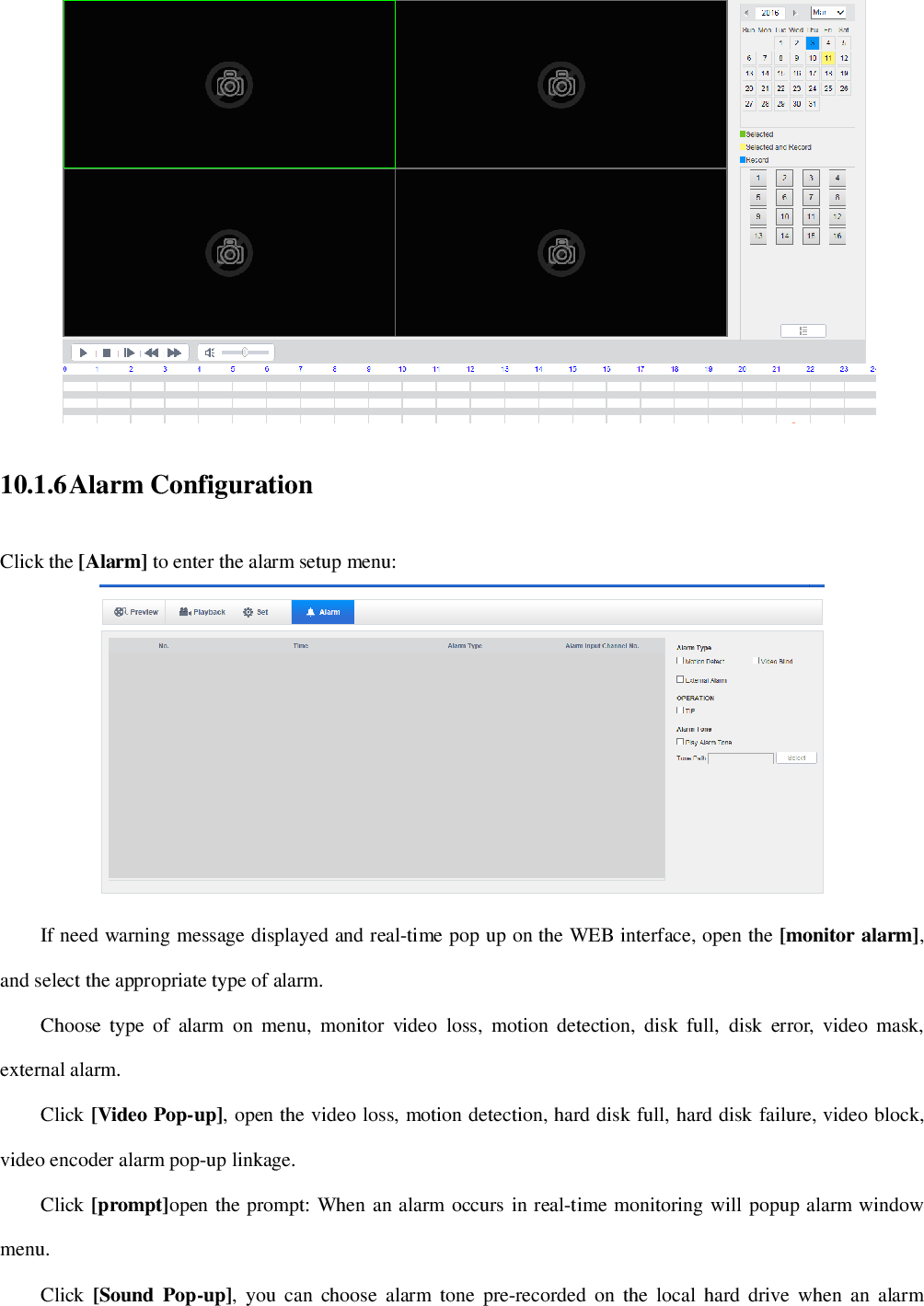
![10.1.6 Alarm Configuration Click the [Alarm] to enter the alarm setup menu: If need warning message displayed and real-time pop up on the WEB interface, open the [monitor alarm], and select the appropriate type of alarm. Choose type of alarm on menu, monitor video loss, motion detection, disk full, disk error, video mask, external alarm. Click [Video Pop-up], open the video loss, motion detection, hard disk full, hard disk failure, video block, video encoder alarm pop-up linkage. Click [prompt]open the prompt: When an alarm occurs in real-time monitoring will popup alarm window menu. Click [Sound Pop-up], you can choose alarm tone pre-recorded on the local hard drive when an alarm](https://usermanual.wiki/HANGZHOU-ZENO-VIDEOPARK-IMPORT-and-EXPORT/IPC/User-Guide-3953627-Page-76.png)
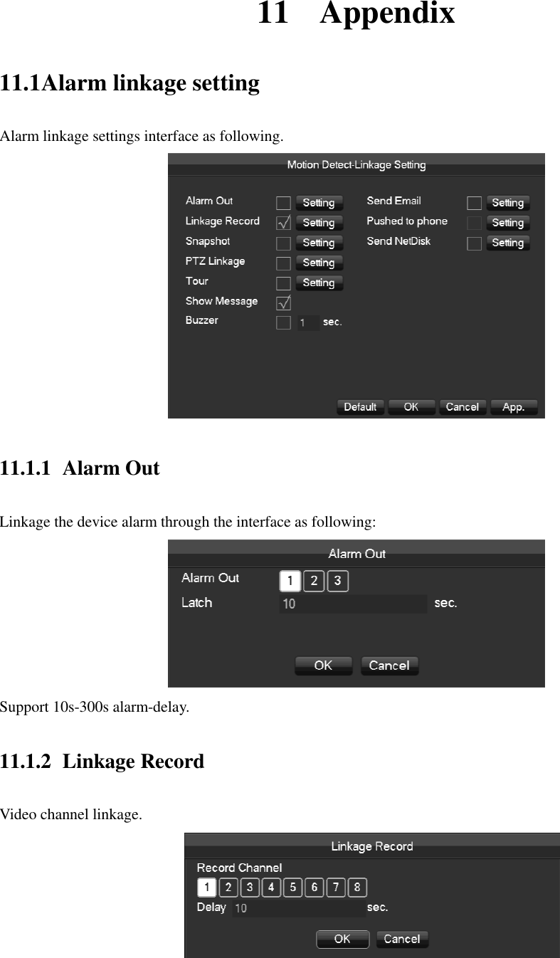
![Support 10s-300s alarm-delay. 11.1.3 Snapshot Screenshots through channel linkage as the interface following: Configure the screenshots by setting [main menu]-[screenshot setting]. If the access channel is the network channel , please check if the screenshot function is open of the camera. 11.1.4 PTZ Linkage Preset position, cruise, trace by setting the PTZ linkage. Preset position, cruise, trace by setting the PTZ configuration. See details on page 6.6.2. 11.1.5 Tour Select the round tour channel when the alarm occurs, select the single channel to the round tour. 11.1.6 Show Message Select the prompt to open the screen, if it occurs alarm, the preview screen will pop up the prompt as following:](https://usermanual.wiki/HANGZHOU-ZENO-VIDEOPARK-IMPORT-and-EXPORT/IPC/User-Guide-3953627-Page-79.png)
![11.1.9 Server Push Server push configuration interface as following: [Send Message] Open or close the mobile phone message sending. [Image Attachment]Open the function of image attachment. [Time Lag] Set the time lag of the message sending, 60s/90s/120s is optional. [Test] Click Send to test the message sending function [Event] Open or close the event sending, the events including external alarm, face detection, perimeter intrusion detection. [Device exception] Open and close the device exceptional sending, the exception including the device startup, no hard dick, error hard dick, start recording/stop recording. [Urgency Degree] The message sending level can be divided into High/Medium/Low level. 11.1.10 Send NetDisk Choose Dropbox, Google drive, according to clew for binding. Support motion detection, video occlusions, local alarm(face/perimeter )alarm and other alarm types. Can linkage other channels to upload the captured pictures](https://usermanual.wiki/HANGZHOU-ZENO-VIDEOPARK-IMPORT-and-EXPORT/IPC/User-Guide-3953627-Page-81.png)
![Function. Routers made by different manufacturers may have some difference, please refer to the specification carefully before setting the Router. The second step Connect the Embedded DVR to the Router; the configuration will automatically gain the IP address or static IP. After setting up the IP, click the Advanced. And get to the XXX, ports and multicast etc. choose to open the Enable at the [UPnP port mapping] The third step Enter into the Router management interface; detect the port if there is already a Port mapping. If there is, it shows UPnP setting’s finished. The forth step Input the IP address in IE, and add port number of the Embedded DVR, for example: 155.157.12.227:81. If you want to enter by the Client Software, use the TCP port offered by the outer net. If there are a few embedded DVRs need to set the UPnP function, in order to avoid IP conflict, set the ports of embedded DVR into different ports numbers. Otherwise, it will choose the embedded DVR port set preceded as the first choice. 11.2.2 Port mapping Manually The first step Connect the Embedded DVR to the Router, set the static IP. The second step Log in Router, enter into the configuration menu of Router, and set the menu. Then get to port, set the IP distributed by the Embedded DVR, and set the rule of port mapping, add HTTP and TCP port into mapping list. Default access ports of Embedded DVR include HTTP port 80 and TCP port 8000, if the ports are occupied by the other device, please modify the default port of the Embedded DVR into other vacant ports. The third step Input the public net IP address in the IE, and add the port number of the Embedded DVR you want to access after the IP, for example: http://155.157.12.227:81. If you want to access by Client Software, you can use the outer net TCP port directly.](https://usermanual.wiki/HANGZHOU-ZENO-VIDEOPARK-IMPORT-and-EXPORT/IPC/User-Guide-3953627-Page-83.png)