HANK ELECTRONICS MS02 MOTION SENSOR User Manual
HANK ELECTRONICS CO., LTD. MOTION SENSOR
UserManual.wiki
>
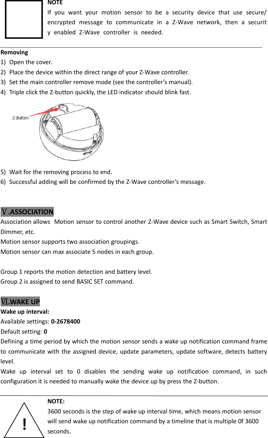
HANK ELECTRONICS
>
MS02 User Manual
User Manual
Navigation menu
Upload a User Manual
Namespaces
Wiki Guide
HTML
PDF
Info
Views
User Manual
Discussion / Help
Navigation

![Setting examples:0~3599 = 0 second, the device will not wake up by itself.3600~7199 = 3600 seconds, the device will wake up every 3600 seconds.Ⅶ.RESETTINGReset procedure clears the motion sensor's memory, including Z-Wavenetwork controller information. To reset Motion sensor:1) Power on the device,2) Press and hold the Z button for more than 20 seconds,3) If holding time more than 20seconds, the LED indicator will keep on for 2 seconds, whichmeans resetting is complete.NOTEUse this procedure only in the event that the network primary controller ismissing or otherwise inoperable.Ⅷ.ADVANCED CONFIGURATIONMotion sensor offers a wide variety of advanced configuration settings. Below parameters can beaccessed from main controllers configuration interface.Parameter NO. 12 MOTION SENSOR’S SENSITIVITYThe higher the value, the more sensitive the PIR sensor.Available settings: 1-8Default setting: 8Parameter size: 1 [byte]Parameter No.14 ENABLE/DISABLE BASIC SET COMMANDMotion sensor can send BASIC SET command to nodes associated with group 2 when motion istriggered.0– Disable.1– Enable.Default setting: 0Parameter size: 1 [byte]](https://usermanual.wiki/HANK-ELECTRONICS/MS02/User-Guide-3666509-Page-6.png)
![Parameter No.15 VALUE OF THE BASIC SETMotion Sensor can reverse its value of BASIC SET when motion is triggered.0–Send BASIC SET VALUE = 255 to nodes associated with group 2 when motion alarm istriggered.Send BASIC SET VALUE = 0 to nodes associated with group 2 when motion alarm is canceled.1–Send BASIC SET VALUE = 0 to nodes associated with group 2 when motion alarm is triggered.Send BASIC SET VALUE = 255 to nodes associated with group 2 when motion alarm iscanceled.Default setting: 0Parameter size: 1[byte]Parameter No.18 MOTION ALARM CANCELLATION DELAYMotion alarm will be canceled in the main controller after 3 seconds, the alarm cancellation canbe delay by this parameter. Any motion detected during the cancellation delay time countdownwill result in the countdown being restarted.Available settings: 0-65535 (seconds)Default setting: 30 (seconds)Parameter size: 2[byte]Parameter No.32 LEVEL OF LOW BATTERYDefine a battery level as the “low battery”.Available settings: 10-50 (10- 50%)Default setting: 20 (20%)Parameter size: 1[byte]Ⅸ.FCC NOTICEThis device complies with part 15 of the FCC Rules. Operation is subject to the following twoconditions:(1) This device may not cause harmful interference, and(2) This device must accept any interference received, including interference that may causeundesired operation.The manufacturer is not responsible for any radio or tv interference caused by unauthorizedmodifications or change to this equipment. Such modifications or change could void the user’sauthority to operate the equipment.This equipment has been tested and found to comply with the limits for a Class B digital device,pursuant to part 15 of the FCC Rules. These limits are designed to provide reasonable protection](https://usermanual.wiki/HANK-ELECTRONICS/MS02/User-Guide-3666509-Page-7.png)