HARRIS BBPBM100 700 MHz LTE Wireless Module User Manual 14221 6200 6000RevCx
Harris Corporation 700 MHz LTE Wireless Module 14221 6200 6000RevCx
HARRIS >
Users Manual
Product Manual
14221-6200-6000
Rev. C, Jan/12
Harris® LTE
PBM-100 Band 14 PCI Express Mini Module
PBM-102 Band 14/12 PCI Express Mini Module
14221-6200-6000, Rev. C
2
MANUAL REVISION HISTORY
REV DATE REASON FOR CHANGE
- Nov/11 Initial release.
A Dec/11 Minor corrections.
B Jan/12 Modified sections 2.2.2 and 2.2.3.
C Jan/12 Modified Section 3.3.
CREDITS
Harris and assuredcommunications are registered trademarks of Harris Corporation. All other brand and product names are
trademarks, registered trademarks, or service marks of their respective owners.
NOTICE!
The material contained herein is subject to U.S. export approval. No export or re-export is permitted without written approval
from the U.S. Government. Rated: EAR99; in accordance with U.S. Dept. of Commerce regulations 15CFR774, Export
Administration Regulations.
Information and descriptions contained herein are the property of Harris Corporation. Such information and descriptions may
not be copied or reproduced by any means, or disseminated or distributed without the express prior written permission of
Harris Corporation, PSPC Business, 221 Jefferson Ridge Parkway, Lynchburg, VA 24501.
Repairs to this equipment should be made only by an authorized service technician or facility designated by the supplier. Any
repairs, alterations or substitutions of recommended parts made by the user to this equipment not approved by the
manufacturer could void the user's authority to operate the equipment in addition to the manufacturer's warranty.
This product conforms to the European Union WEEE Directive 2002/96/EC. Do not dispose of this
product in a public landfill. Take it to a recycling center at the end of its life.
This manual is published by Harris Corporation without any warranty. Improvements and changes to this manual
necessitated by typographical errors, inaccuracies of current information, or improvements to programs and/or equipment,
may be made by Harris Corporation at any time and without notice. Such changes will be incorporated into new editions o
f
this manual. No part of this manual may be reproduced or transmitted in any form or by any means, electronic or mechanical,
including photocopying and recording, for any purpose, without the express written permission of Harris Corporation.
Copyright © 2011, 2012 Harris Corporation. All rights reserved.
14221-6200-6000, Rev. C
3
TABLE OF CONTENTS
Section Page
1 INTRODUCTION .......................................................................................................................... 4
1.1 DESCRIPTION ......................................................................................................................... 4
1.2 SCOPE .................................................................................................................................... 4
2 REGULATORY AND SAFETY INFORMATION .................................................................... 5
2.1 REGULATORY APPROVALS ............................................................................................ 5
2.1.1 Transmitter ............................................................................................................... 5
2.1.2 Receiver .................................................................................................................... 5
2.1.3 FCC Compliance ...................................................................................................... 5
2.1.4 Industry Canada ........................................................................................................ 5
2.1.5 Labeling .................................................................................................................... 6
2.2 RF ENERGY EXPOSURE INFORMATION ....................................................................... 6
2.2.1 Maximum Permissible Exposure Limits .................................................................. 6
2.2.2 MPE Calculation for Mobile Device Installation ..................................................... 7
2.2.3 Maximum Allowed Antenna Gain ........................................................................... 7
3 INSTALLATION GUIDELINES ................................................................................................. 8
3.1 INTRODUCTION ...................................................................................................................... 8
3.2 MOBILE HOST ........................................................................................................................ 8
3.3 PORTABLE HOST .................................................................................................................... 8
3.4 COLLOCATED TRANSMITTERS ............................................................................................... 8
4 SPECIFICATIONS ........................................................................................................................ 9
4.1 GENERAL SPECIFICATIONS ............................................................................................ 9
4.2 TRANSMITTER SPECIFICATIONS ................................................................................... 9
4.3 RECEIVER SPECIFICATIONS ........................................................................................... 9
5 CUSTOMER SERVICE .............................................................................................................. 10
5.1 CUSTOMER CARE ................................................................................................................. 10
5.2 TECHNICAL ASSISTANCE ...................................................................................................... 10
FIGURES
Figure 1-1: PCI Express Mini (PEM) Module ....................................................................................... 4
Figure 2-1: FCC Labeling ...................................................................................................................... 6
TABLES
Table 2-1: MPE Limits .......................................................................................................................... 7
Harris Corporation, Public Safety and Professional Communications (PSPC) Business continually evaluates its technical
publications for completeness, technical accuracy, and organization. You can assist in this process by submitting your
comments and suggestions to the following:
Harris Corporation fax your comments to: 1-434-455-6851
PSPC Business or
Technical Publications e-mail us at: PSPC_TechPubs@harris.com
221 Jefferson Ridge Parkway
Lynchburg, VA 24501
14221-6200-6000, Rev. C
4
1 INTRODUCTION
1.1 DESCRIPTION
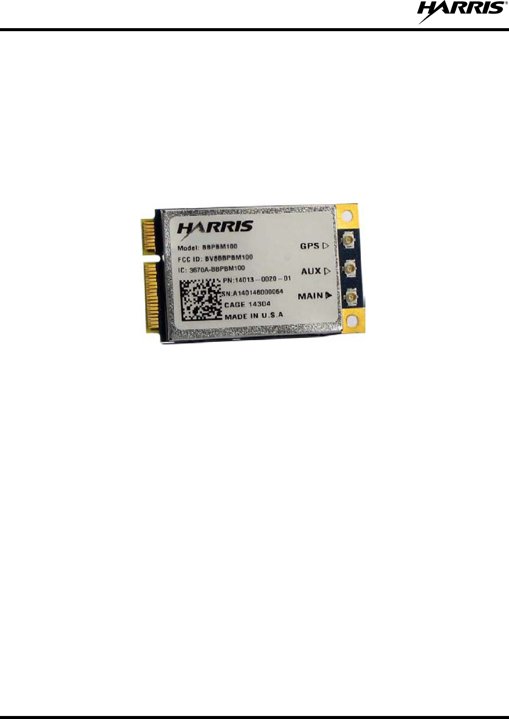
The PCI Express Mini (PEM) module functions as LTE User Equipment (UE) capable of interoperating
with the Harris LTE network and is deployed by integrating into the current generation of laptop
computers and mobile data terminals. The PEM is capable of dual-band operation supporting UMTS
bands 14 and 12, and conforms to the PCI Express Mini specification as a Type F1 Full-Mini (50.9 × 30.0
× 5.0 mm³), as shown below, for integration into devices as a USB modem. The PEM card is a modular
transmitter and is not shipped with antennas.
Figure 1-1: PCI Express Mini (PEM) Module
The module is supplied under two part product codes:
The PBM-100 is a single LTE band device operating in 3GPP band 14 in the spectrum dedicated to
public safety.
The PBM-102 is a dual LTE band device which has the capability of operation in 3GPP band 14 and
band 12.
1.2 SCOPE
This document outlines the use and installation guidelines for the PEM module into host devices.
14221-6200-6000, Rev. C
5
2 REGULATORY AND SAFETY INFORMATION
2.1 REGULATORY APPROVALS
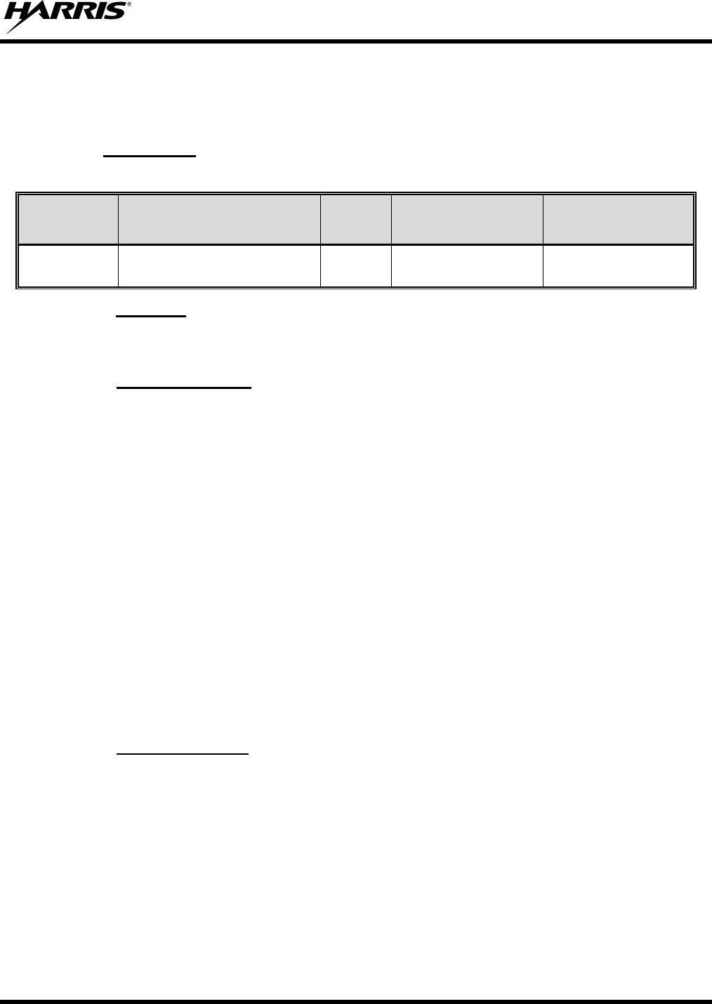
2.1.1 Transmitter
The transmitting devices listed below have been tested and meet the following regulatory requirements:
MODEL DESCRIPTION BW
(MHz) FCC ID
(PART 90)
INDUSTRY
CANADA
(RSS-119)
PBM-100
PBM-102
700 MHz LTE B14 PEM Module
700 MHz LTE B14/12 PEM Module
5
5 or 10 BV8BBPBM100 3670A-BBPBM100
2.1.2 Receiver
The receiver associated with this transmitting device has been tested and declared to meet the regulatory
requirements.
2.1.3 FCC Compliance
This device complies with Part 15 of the FCC Rules. Operation is subject to the condition that this device
does not cause harmful interference.
The user should take caution that changes or modifications not expressly approved by Harris could void
the user’s authority to operate this equipment. All required software and operating conditions must not be
violated by the installer/user and is an express condition of use for this equipment.
This equipment has been tested and found to comply with the limits for a Class B digital device, pursuant
to Part 15 of the FCC Rules. These limits are designed to provide reasonable protection against harmful
interference in a residential installation. This equipment generates, uses, and can radiate radio frequency
energy and, if not installed and used in accordance with the instructions, may cause harmful interference
to radio communications. However, there is no guarantee that interference will not occur in a particular
installation. If this equipment does cause harmful interference to radio or television reception, which can
be determined by turning the equipment off and on, the user is encouraged to try to correct the
interference by one or more of the following measures:
Reorient or relocate the receiving antenna.
Increase the separation between the equipment and receiver.
Consult an experienced radio/TV technician for help.
2.1.4 Industry Canada
This Class B digital apparatus complies with Canadian ICES-003.
Cet appareil numérique de la classe B est conforme à la norme NMB-003 du Canada.
The installer of this radio equipment must ensure that the antenna is located or pointed such that it does
not emit RF field in excess of Health Canada limits for the general population; consult Safety Code 6,
obtainable from Heath Canada’s website www.hc-sc.gc.ca/rpb.
14221-6200-6000, Rev. C
6
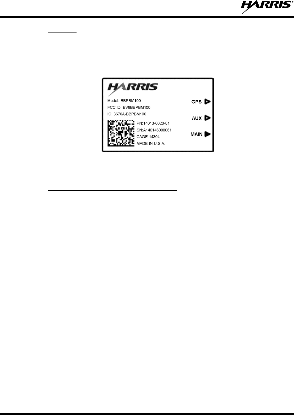
2.1.5 Labeling
The FCC labeling of the PEM module is shown below. When integrating the module into a host, the label
must be visible through a window, visible through an access panel that is easily removed, or a second
label must be placed on the outside of the host device that contains the following text: Contains FCC ID:
BV8BBPBM100. Labelling for Canada must include the following text: Contains IC: 3670A-
BBPBM100.
Figure 2-1: FCC Labeling
2.2 RF ENERGY EXPOSURE INFORMATION
2.2.1 Maximum Permissible Exposure Limits
Mobile devices are defined by the FCC as transmitters with a separation distance of at least 20
centimeters between radiating structures and the body of the user. At least 20 centimeters of separation
between the antenna and the users body must be maintained at all times.
The FCC defines portable devices as transmitters whose radiating structures are designed to be used
within 20 centimeters of the body of the user. These portable devices are to be evaluated with respect to
limits for specific absorption rate (SAR) and requires separate approval.
The Maximum Permissible Exposure (MPE) is based on a mobile device installation and is based on
“Limits for General Population/Uncontrolled Exposure” as specified in FCC rules 47 CFR 1.1310. The
limit for Uncontrolled Exposure Power Density (Pd ) is 0.527 mW/cm2 for UMTS Band 14 operation. .
The limit for Uncontrolled Exposure Power Density (Pd ) is 0.467 mW/cm2 for UMTS Band 12
operation.
14221-6200-6000, Rev. C
7
2.2.2 MPE Calculation for Mobile Device Installation
Given the limit for power density, we can calculate the maximum antenna gain allowed for use in a
mobile installation. This MPE Maximum Gain Calculation is based on a mobile device antenna at a
distance of 20 cm or greater between the radiating structure and the user. Friis transmission equation is
used to perform the calculation.
Friis Transmission Equation:
4
Rearranging the equation to solve for gain and substituting, the calculation indicates that the maximum
gain allowed when operating in Band 14 is:
0.527
316 ·420
9.23
Where:
GT is the Maximum Antenna Gain
PT is the Maximum Transmitted Power = 316 mW
pr is the Maximum Received Power Density = 0.527 W/cm²
R is the Minimum Distance between User and Antenna = 20 cm
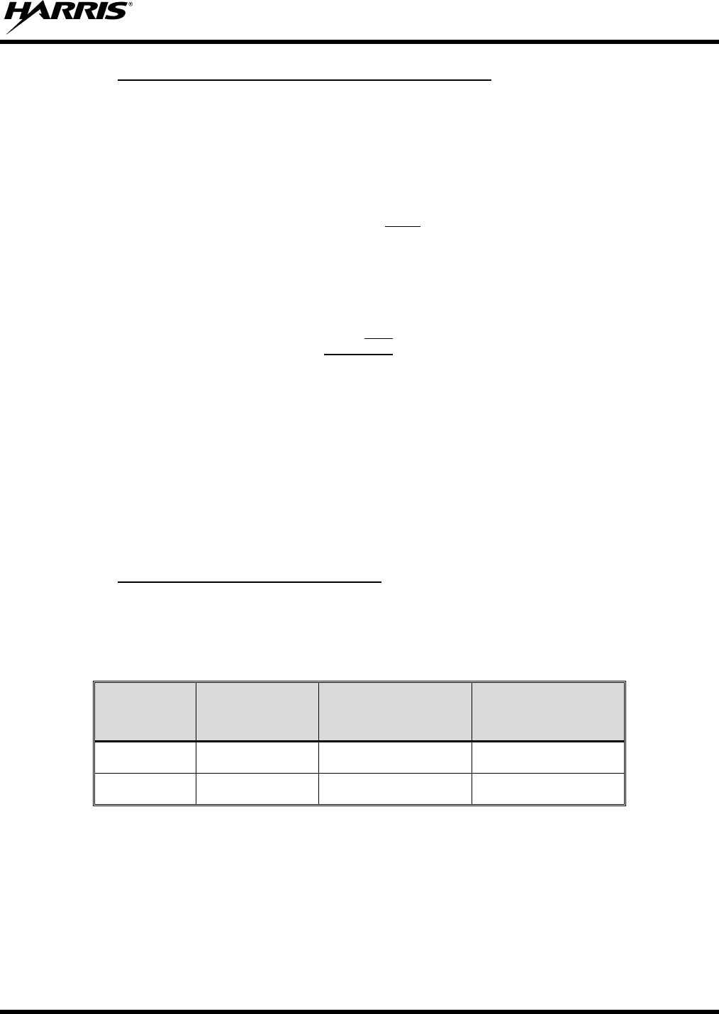
2.2.3 Maximum Allowed Antenna Gain
The following table summarizes the maximum gain allowed for use in mobile installations at each band of
operation. When designing the antenna system for the PEM, the gain of the host antenna must not exceed
these values.
Table 2-1: MPE Limits
UMTS
Operating
Band
Transmitter
Frequency
Uncontrolled Exposure
Power Density
Maximum
Antenna Gain
12 700.5 MHz 0.467 mW/cm² 8.71 dBi
14 790.5 MHz 0.527 mW/cm² 9.23 dBi

14221-6200-6000, Rev. C
8
3 INSTALLATION GUIDELINES
3.1 INTRODUCTION
Careful planning and preparation of any installation will always benefit the end result; always read and
follow all installation instructions. Follow ESD precautions and prepare an ESD safe workspace for
installation. Turn the power to the host off and ground yourself to dissipate static charge.
Mount only in sockets and locations intended for Type F1 Full-Mini cards and consult Harris on thermal
management recommendations for the PEM mounted within the host.
All instructions relating to the integration of the module described on the FCC Grant notes must be
followed.
3.2 MOBILE HOST
The PEM can be installed in host devices as a standalone transmitter where the distance between the
antenna and the body of the user is greater than 20 centimeters and the antenna gain is less than the value
shown in section 2.2.3. Labeling requirements are given in section 2.1.5.
3.3 PORTABLE HOST
In host devices where the distance between the antenna and the body of the user is equal to or less than 20
centimeters, the device must be evaluated using specific FCC and Industry Canada test procedures for
SAR and requires separate approval. Users are required to consult with Harris for all portable
installations.
3.4 COLLOCATED TRANSMITTERS
This module can be incorporated in mobile host devices containing other transmitters if:
The separation among all simultaneous transmitting antennas is ≥ 20 cm.
OR
Antennas comply with MPE limits as specified in the application filing and simultaneously
transmitting antennas must be ≥ 5 cm from each other.
As with any mobile installation, all antennas must be at least 20 cm from users and nearby persons.
All collocated transmitter installations must be evaluated by Harris.

14221-6200-6000, Rev. C
9
4 SPECIFICATIONS
4.1 GENERAL SPECIFICATIONS
Model Number:
PBM-100/PBM-102
Physical Characteristics:
Electrical Power: 3.3 Vdc
Power Consumption: 3.5 Watts maximum
Size (H x W x D): 50.9 × 30.0 × 4.2 mm (2.0 x 1.18 x .17 in)
Weight: 13 g (.46 oz)
Environmental Specifications:
Operating Temperature: -30°C to +60°C (-22°F to +140°F)
Storage Temperature: -40°C to +85°C (-40°F to +185°F)
Altitude: 15,000 ft. (operational)
System Interfaces:
Host PCI Express Mini (USB)
LTE U.FL-R connector
4.2 TRANSMITTER SPECIFICATIONS
Frequency: 788 – 798 MHz, 698 – 716 MHz
Channel Bandwidth: 5 or 10 MHz
RF Power Output: +23 dBm maximum
Output Power Control: 50 dB
FCC ID: BV8BBPBM100
Industry Canada: 3670A-BBPBM100
4.3 RECEIVER SPECIFICATIONS
Frequency 758 – 768 MHz, 728 – 746 MHz
Channel Bandwidth: 5 or 10 MHz
Sensitivity (5MHz QPSK) -97 dBm
Max RX Input Power: -25 dBm
Max RX Input Power (no damage): 0 dBm
14221-6200-6000, Rev. C
10
5 CUSTOMER SERVICE
5.1 CUSTOMER CARE
If any part of the system equipment is damaged on arrival, contact the shipper to conduct an inspection
and prepare a damage report. Save the shipping container and all packing materials until the inspection
and the damage report are completed. In addition, contact the Customer Care center to make
arrangements for replacement equipment. Do not return any part of the shipment until you receive
detailed instructions from a Harris representative.
Contact the Customer Care center at http://www.pspc.harris.com/CustomerService or:
North America:
Phone Number: 1-800-368-3277
Fax Number: 1-321-409-4393
E-mail: PSPC_CustomerFocus@harris.com
International:
Phone Number: 1-434-455-6403
Fax Number: 1-321-409-4394
E-mail: PSPC_InternationalCustomerFocus@harris.com
5.2 TECHNICAL ASSISTANCE
The Technical Assistance Center's (TAC) resources are available to help with overall system operation,
maintenance, upgrades and product support. TAC is the point of contact when answers are needed to
technical questions.
Product specialists, with detailed knowledge of product operation, maintenance and repair provide
technical support via a toll-free (in North America) telephone number. Support is also available through
mail, fax and e-mail.
For more information about technical assistance services, contact your sales representative, or call the
Technical Assistance Center at:
North America: 1-800-528-7711
International: 1-434-385-2400
Fax: 1-434-455-6712
E-mail: PSPC_tac@harris.com

14221-6200-6000, Rev. C
11
NOTES

Public Safety and Professional Communications | www.pspc.harris.com
221 Jefferson Ridge Parkway | Lynchburg, VA USA 24501 | 1-800-528-7711