HARRIS CS803 Digital Trunked Control Station User Manual CS 803 Operators Manual Rev C
Harris Corporation Digital Trunked Control Station CS 803 Operators Manual Rev C
HARRIS >
Manual
Operator’s Manual
OpenSky CS-803/
SP-103/TRCM-103
Digital Trunked Control Station
OpenSky is a registered trademark of M/A-COM, Inc.
NOTICE!
This manual covers M/A-COM products manufactured and sold by M/A-
COM, Inc.
NOTICE!
Repairs to this equipment should be made only by an authorized service
technician or facility designated by the supplier. Any repairs, alterations
or substitutions of recommended parts made by the user to this equipment
not approved by the manufacturer could void the user's authority to
operate the equipment in addition to the manufacturer's warranty.
This manual is published by M/A-COM, Inc., without any warranty. Improvements and
changes to this manual necessitated by typographical errors, inaccuracies of current
information, or improvements to programs and/or equipment, may be made by M/A-COM,
Inc., at any time and without notice. Such changes will be incorporated into new editions of
this manual. No part of this manual may be reproduced or transmitted in any form or by any
means, electronic or mechanical, including photocopying and recording, for any purpose,
without the express written permission of M/A-COM, Inc.
Copyright 2003 M/A-COM, Inc. All rights reserved.
3
Proper Radio Use, Installation, and Service
Introduction Use, installation, and service of the CS-803 radio
as summarized below will ensure the safe
performance of this equipment. Use of this radio as
described below will result in user exposure
substantially below the FCC recommended limits
for human exposure to Radio Frequency
Electromagnetic energy.
Proper Use Do not operate this radio if any of the RF connectors
are not secure or if open connections are not properly
terminated.
Proper
Installation
and Service
The CS-803 radio and antenna must be
professionally installed by experienced antenna
installation professionals. During the installation of
directional antennas, the installer must not point the
main beam of the antenna to locations occupied by
persons within the distance of maximum permissible
exposure limits specified in Part 2 of the FCC
regulations. Failure to follow these instructions will
void the product warranty and may expose the end
user and others to excessive Radio Frequency hazard.
All antennas are intended to be installed outdoors and
at distances from personnel well beyond the
minimum allowable distance.
Proper grounding is necessary, not only for correct
functionality and maximum performance, but for
minimizing damage that may occur from lightning
strikes. The CS-803 radio and the SP-103 do not
include a lightning-protection device, but it is
recommended and only effective if the connection is
made as the design intended. Follow the installation
instructions to ensure a properly grounded unit.
FCC regulations This device complies with Part 15 of the FCC
Rules. Operation is subject to the following
two conditions: (1) this device may not cause
harmful interference; and (2) this device must
accept any interference received, including
interference that may cause undesired
operation.
This device is not required to comply with the
FCC RF exposure limits for Uncontrolled
Exposure (General Population) and
Occupational Exposure, because it is assumed
that neither uncontrolled nor occupational
exposure is applicable in the general
installation configuration. The installation of
the antenna for the CS-803 is to be performed
such that no person is within 10 meters during
normal operation, and the CS-803 must be
disabled before maintenance to the antenna is
attempted.
The Federal Communications Commission
(FCC) requires the user to obtain a station
license for this radio equipment before
operating it.
The operator is responsible at all times for the
proper operation and maintenance of the
equipment.
FCC regulations state that the frequency,
deviation, and power of a radio transmitter
must be maintained within specified limits. It
is recommended, therefore, that these three
parameters be checked before the station is
placed in service.
5
Important
Safety
Instructions
1) Read these instructions.
2) Keep these instructions.
3) Heed all warnings.
4) Follow all instructions.
5) Do not use this apparatus near water.
6) Clean only with dry cloth.
7) Do not block any ventilation openings.
Install in accordance with the
manufacturer’s instructions.
8) Do not install near any heat sources such
as radiators, heat registers, stoves, or
other apparatus (including amplifiers)
that produce heat.
9) Do not defeat the safety purpose of the
polarized or grounding-type plug. A
polarized plug has two blades with one
wider than the other. A grounding type
plug has two blades and a third
grounding prong. The wide blade or the
third prong is provided for your safety. If
the provided plug does not fit into your
outlet, consult an electrician for
replacement of the obsolete outlet.
10) Protect the power cord from being
walked on or pinched particularly at
plugs, convenience receptacles, and the
point where they exit from the apparatus.
11) Only use attachments/accessories
specified by the manufacturer.

12) Use only with the cart, stand, tripod,
bracket, or table specified by the
manufacturer, or sold with the apparatus.
When a cart is used, use caution when
moving the cart/apparatus combination
to avoid injury from tip-over.
13) Unplug this apparatus during lightning
storms or when unused for long periods
of time.
14) Refer all servicing to qualified service
personnel. Servicing is required when
the apparatus has been damaged in any
way, such as power-supply cord or plug
is damaged, liquid has been spilled or
objects have fallen into the apparatus,
the apparatus has been exposed to rain or
moisture, does not operate normally, or
has been dropped.
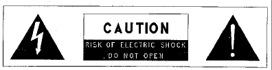
15) Warning: The lightning bolt signifies an
alert to the user of the presence of
uninsulated “dangerous voltage” within
the product’s enclosure that may be of
significant magnitude to constitute a risk
of electric shock to persons.
7
16) Warning: The exclamation point alerts
the user to the presence of important
operation and maintenance (service)
instructions in the literature
accompanying the product.
17) Outdoor Use Warning: To reduce the
risk of Fire or Electric Shock, Do Not
Expose This Apparatus to Rain or
Moisture.
18) Wet Location Warning: Apparatus shall
not be exposed to dripping or splashing
and no objects filled with liquids, such
as vases, shall be placed on the
apparatus.

TABLE OF CONTENTS
1 PRODUCT DESCRIPTION................................................................10
1.1 VOICE AND DATA OPERATION........................................................ 11
1.2 REAR PANEL...................................................................................... 11
2 OPERATION...........................................................................................12
2.1 OPERATION WITH THE SP-103 OR CH-103................................... 12
2.1.1 User Interface Components...................................................12
2.1.2 Display Screen Overview.......................................................15
2.1.3 Operating the Control Station with an SP-103 or CH-10318
2.1.4 Lock Out Talkgroup................................................................28
2.1.5 Select Scan Mode....................................................................30
2.1.6 Emergency Communications.................................................33
2.1.7 Selective Call...........................................................................34
2.1.8 Dynamic Regrouping..............................................................35
2.2 OPERATION WITH THE TRCM-103 AND THIRD PARTY TONE REMOTE DESK
SET 35
2.2.1 How to turn the Control Station/TRCM-103 on................35
2.2.2 How to Log on to the Network..............................................36
2.2.3 Self-Test ....................................................................................37
2.2.4 How to Turn the Control Station/TRCM-103 Off ..............37
2.2.5 How to Change the Volume...................................................37
2.2.6 Voice Calls...............................................................................38
2.2.7 Radio Tones..............................................................................38
FIGURES
FIGURE 1-1: REAR PANEL................................................................................. 11
FIGURE 2-1: CH-103 CONTROL HEAD............................................................ 12
FIGURE 2-2: SP-103 SKYPORT......................................................................... 13
FIGURE 2-3: SAMPLE DISPLAY SCREEN.......................................................... 16
FIGURE 2-4: SIDE TONES MENU....................................................................... 24
FIGURE 2-5: PROFILE SELECTION MENU........................................................ 26
FIGURE 2-6: TALKGROUP SELECTION MENU ................................................. 27

9
TABLES
TABLE 2-1: USER INTERFACE CONTROLS AND FUNCTIONS......................... 14
TABLE 2-2: DISPLAY PARTS AND FUNCTIONS............................................... 17
TABLE 2-3: SAMPLE SETUP : DWELL DISPLAY HIERARCHY........................ 18
TABLE 2-4: SIDE TONES MENU COMPONENTS.............................................. 25
TABLE 2-5: BRIGHTNESS SELECTION MENU COMPONENTS........................ 25
TABLE 2-6: PROFILE SELECTION MENU COMPONENTS................................ 26
TABLE 2-7: TALKGROUP SELECTION MENU COMPONENTS......................... 27
TABLE 2-8: LOCKOUT SELECTION MENU....................................................... 29
TABLE 2-9: SCAN MODES................................................................................. 30
1 Product Description
Your CS-803 Digital Control Station is a hardware component of
the OpenSky network, an integrated voice and data
communications system that delivers end-to-end digital
transmissions over a single wireless network to various subscriber
units.
The CS-803 is intended to operate in an office environment,
typically for dispatch purposes. The radio operates over both the
Specialized Mobile Radio (SMR) and National Public Safety
Planning Advisory Committee (NPSPAC) frequency bands. These
bands provide a total of over 830 possible channels spread over
the 806-824 MHz transmission and 851-869 MHz reception bands.
The CS-803 operates full duplex with an 18W (typical) transmit
output power.
The CS-803 uses Time Division Multiple Access (TDMA)
technology to allow multiple users to share a single RF channel. In
addition, a single 25kHz RF channel can support simultaneous
digital voice and data communications. Depending on the user
configuration of the network or agency, the radio supports the
OpenSky digital protocol as well as Conventional FM.
The CS-803 provides voice and data services in a dispatch
operation. Voice operation is provided through various CS-803
compatible user interfaces that use a microphone and speaker. For
data transfers or graphics, the CS-803 is constructed with an
industry-standard RS-232 interface serial port for connecting
optional equipment such as a Mobile Data Terminal (MDT), laptop
PC or third-party display or key-entry device. OpenSky works
seamlessly with equipment from popular manufacturers and off-
the-shelf applications through a standard UDP/IP protocol,
providing you with simple “plug and play” connectivity.
A host terminal, not included with the CS-803, provides data
connectivity through the standard RS-232 serial (DCE) interface.
Your CS-803 is a “soft” radio. Its functions are determined by
whichever release of OpenSky software applications are installed.
11
1.1 Voice and Data Operation
In Conventional FM mode, the voice path operates like a traditional
dispatch radio, with a microphone to transmit (push-to-talk) and a
speaker to receive. The data path operates similarly to the voice
path, but has a few slight differences.
In OpenSky Trunked Protocol (OTP), there is no separate voice
and data path – all transmitted information is digital. The system is
TDMA based, and operates at a data rate of 19.2 kbps. All data
information in and out of the control station uses the RS-232 serial
port.
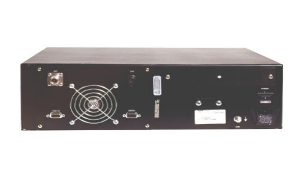
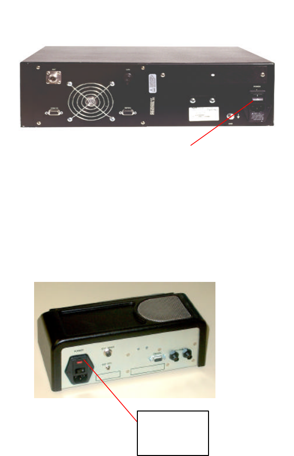
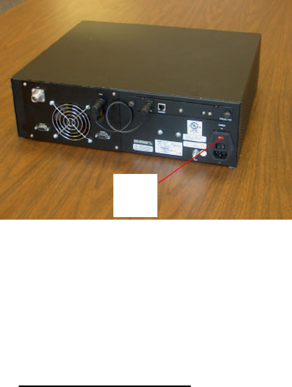
1.2 Rear Panel
The CS-803 Rear Panel Assembly, Figure 1-1, contains all of the control
station interfaces. Power to the CS-803 is controlled by an on/off switch
and provided by a normal AC switched line. The rear panel also includes
an antenna port, an RS-232 serial port, an I/O communication port, and a
CAN port to connect optional OpenSky user interfaces such as the
SkyPort Desk Set (SP-103), the Control Head (CH-103), and the Tone
Remote Control Module (TRCM-103) which allows the user to connect
to off the shelf Tone Remote Desk Sets. The optional TRCM -103 mounts
in the back of the CS-803.
Figure 1-1: Rear Panel

2 OPERATION
2.1 Operation with the SP-103 or CH-103
2.1.1 User Interface Components
User interfaces such as the CH-103 and the SP-103 for your CS-
803 include Power Button/Speaker Volume Dials, the
Microphone/Speaker I/O Port, a 5-key “soft-button” keypad for
making menu selections, a 19-character vacuum fluorescent
Display Panel, 3 Mode Selector buttons, an Emergency Button
(CH-103 and SP-103 only) and an Ambient Light sensor.
Additionally, the SP-103 includes a 12-position DTMF keypad.
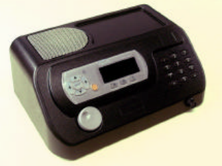
Figure 2-1 shows a Control Head Unit (CH-103) and Figure 2-2
shows a SkyPort (SP-103), which are two of the available user
interface accessories for the CS-803 Control Station.
Figure 2-1: CH-103 Control Head
13
Figure 2-2: SP-103 SkyPort

Table 2-1: User Interface Controls and Functions
PART FUNCTION
POWER
Button/Volume
Dial
(CH-103 only,
SP-103 has AC
power with
on/off switch on
back of unit)
Push to Power Up.
Push again to Power Down.
Twist clockwise to increase speaker
volume.
Twist counter-clockwise to decrease
speaker volume.
Mic Connection
Attach hand-held microphone, hands-free
speaker, or keypad, microphone here.
Headset mic/spkr and desk mics also
available.
EMERGENCY
button
In the OpenSky Protocol, when suitably
configured, pressing this button will send
an emergency alert and open voice
communication with your default
emergency talkgroup.
LIGHT sensor User interface automatically selects Display
Panel brightness level based on ambient
light. You should not block this sensor.
MENU and
SELECTOR
buttons
Cycle through the menu loop with UP and
DOWN buttons.
Scroll through selections with LEFT and
RIGHT buttons.
Press SELECT button to indicate your final
choice.
DISPLAY area Menu selections appear here, along with
Data Connectivity and Volume
indicators.
User may select which of several DWELL
SCREENS the radio will display.

15
PART FUNCTION
MODE
SELECTOR
buttons
Depending on setup choices made by your
Network Administrator, you’ll use these
buttons to choose between software modes
(FM, OTP), voice groups or channel
presets.
DTMF Keypad
3x4 array (SP-
103 only
Depending on setup choices made by your
Network Administrator, you’ll use the
DTMF keypad for specific tasks such as
entering a User ID and Password , or
selective calling via the radio.
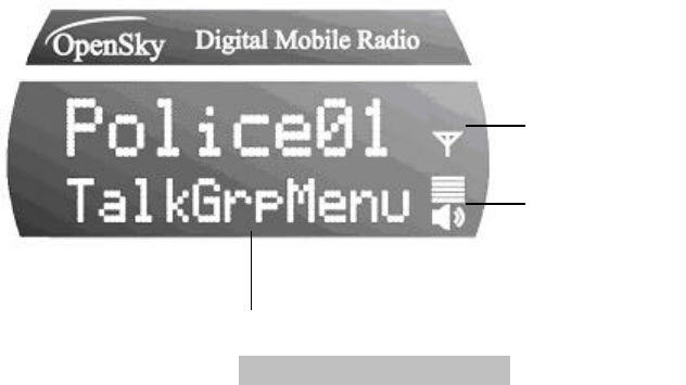
2.1.2 Display Screen Overview
The display screen shows the status of your control station
setup. Data connectivity and volume indicators reside in the
right-hand sector. The rest of the screen is devoted to a 2-line
vacuum fluorescent display that changes in response to user
interaction with the Menu Selection keys. See Figure 2-3 for
illustrations of the display items.
Data Connectivity
(Looks like an antenna)
Presence of this icon indicates data network connectivity.
Speaker Volume Icon
(Looks like a speaker)
This icon indicates user-selected speaker volume setting. Twist
the volume knob to change this setting.
Selection Display
(The top line of text)
This display changes as you press the Left and Right menu
selector buttons to scroll through the selections in the active
menu loop.
Menu Display
(The bottom line of text)
The Menu Display changes as you press the Up and Down
menu selector buttons to scroll through the menu loop.
Dwell Display
(The user-defined display default)
When not engaged in menu selection, the 2-line VF display
defaults to the user-selected Dwell Display. The top line shows
the current Transmit Talkgroup. The bottom line shows the
user’s choice of the current Profile, Received Talkgroup/Caller ID
(when available), and Channel (when enabled).
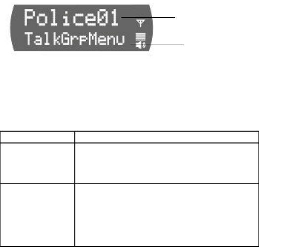
Sample Display Screen
Figure 2-3 reflects just one of many possible displays for a
display screen. There is no pre-selected default screen for the
OpenSky II Phase 2 protocols. Instead, each user will select the
display condition of his/her choice by making a selection from the
Dwell Display menu.
Figure 2-3: Sample Display Screen
Network
Connectivity
Indicator
Volume
Indicator
Sample Display Screen showing
a Talk Group Menu session

17
Table 2-2: Display Parts and Functions
COMPONENT FUNCTION
Data
Connectivity
Icon
Resident in every display screen. If
this icon is displayed, there is a data
connection. If the icon is not present,
there is no data connection.
VOLUME
Icon
Resident in every display screen.
Shows current speaker volume setting
chosen by the user.
MENU
SELECTION
Display
During a menu session, the bottom
line responds to the Up and Down
menu buttons to show the active
menu (Talkgroup Menu in this case).
The top line responds to the Left and
Right menu buttons to display the
options within that menu (available
Talkgroups within the active profile
in this example).
Menu Display and Control Area
Following power-up, the display shows the selected Talkgroup.
Pressing the MENU button up or down (Table 2-2) changes the
display to the next available menu. The dwell display is displayed
if you are not pressing the menu keys. If you switch to another
menu, the user interface will return to the dwell display if no key
is pressed for 10 seconds.
After any Menu/Select procedure, your display screen will revert
to whatever display you have chosen as your dwell display.
Once the dwell display is active, it will change dynamically to
reflect the current profile, received Talkgroup/caller ID (when
available), or channel (when enabled).
The user interface display screens are highly interactive and
respond with a changing display in the upper and lower text lines
as the user presses the Menu Selection buttons to scroll through
the menu loop and the entries under each menu.
When the button pressing stops, the screen will revert to the
dwell display and show the status of whichever category of
information the user has selected from the dwell display menu.

Dwell Display User-Selectable
The first line of any Dwell Display for Open Sky trunked mode
operation is always the selected Talkgroup for your selected
profile. What appears in the second line, depends on what
choice you make for your default display preference.
Whatever your preference, your control station user interface will
respond dynamically to changes in status, always displaying the
current information about your network connection. You may
elect to have the screen display your current Profile, Received
Talkgroup/Caller ID (when available), or Channel (when
enabled).
Table 2-3 shows the choices available for dwell display and
some representative options available under each menu
heading. Setups vary widely from network to network; do not
expect to find these actual options in your menu.
Table 2-3: Sample Setup: Dwell Display Hierarchy
PROFILE
RECEIVED
TALKGROUP/
CALLER CHANNEL
(WHEN ENABLED)
TACTICAL POLICE 01 OT450
SOUTH DISPATCH OT460
HIGHWAY EMS 09 OT550
METRO No Calls OT999
Changing your Dwell Display choice is as simple as any other
menu selection operation.
See the chapter on Display Screen Functions for step-by-step
instructions on how to select or change your Dwell Display.
2.1.3 Operating the Control Station with an SP-
103 or CH-103
19
How to turn the Control Station/SP-103 on
1. Push the Power Switch on the rear panel of the CS-
803. An LED on the front of the CS-803 will illuminate to
indicate Power Up.
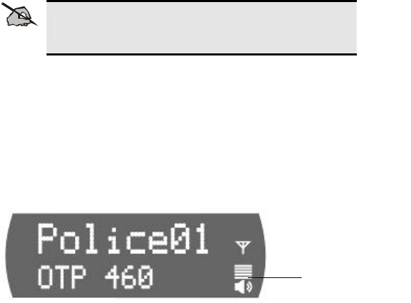
2. Push the Power Switch on the rear panel of the SP-
103. The user interface display will display Booting
Please Wait.
CS-803
Power
Switch
SP-103
Power Switch

3. Wait through the Startup Sequence, which lasts
approximately 10 seconds.
During this time your control station is provisioned with
your customized user personality, emergency conduct
and user specifications, all designed for your specific
needs by the Network Administrator and prompted by
your User ID.
4. When provisioning is complete, the CS-803 user
interface located on the SP-103 or CH-103 will display
the Dwell Display in the Display Screen.
5. The Speaker Volume indicator displays your current
volume setting. Rotate the Power Button/ Volume Dial
clockwise to increase the volume, counter-clockwise to
reduce the volume.
How to Log on to the Network
Network log-on is either automatic or directed via a PC. Even if
you want to use your control station for non-network traditional
RF communications, you will still need to log on to the network
first, then select Talkaround Mode to work off-network.
Contact your local administrator for procedures on how to log
onto the Network.
Self-Test
After Power Up, your CS-803 control station undergoes a multi-
function automatic Boot procedure. Your control station is
provisioned with your user personality: as many as 16 user
profiles are downloaded to your equipment from the network in
response to your User ID. Emergency behavior is provisioned
along with each profile.
Your control station conducts a diagnostic Built-In Self-Test
(BIST). The Self-Test is a battery of hardware diagnostic tests on
the internal components of the control station. All processor and
User-Selected
Dwell Display
Current
Volume Setting
21
memory elements, interfaces, connectivity elements, and RF
functionalities are diagnosed for operational integrity.
How to Turn the Control Station/SP-103 Off
6. Push the Power Switch on the rear panel of the CS-803 and
the SP-103. The LED on the front of the CS-803 and the
user interface on the SP-103 will cease to illuminate to
indicate Power Down.
7. Several user-selected radio settings will survive the Power
Down procedure.
8. At your next Power Up, these saved settings will
automatically default, along with your network personality
settings.
How to Change the Volume
NOTE
Your user interface Display Screen always displays the
current volume, whether or not a call is being received.
9. Rotate the Power Button/Volume Dial on the user interface
clockwise to increase the Speaker Volume.
10. Rotate the Power Button/Volume Dial on the user interface
counter-clockwise to decrease the Speaker Volume.
11. Whether you are receiving a voice call or not, your volume
setting change will immediately reflect in the display screen
Speaker Volume indicator.
Speaker Volume
Indicator
Voice Calls
As soon as your control station completes the Startup/Log
On/Provision/Self-Test sequence and registers on the OpenSky
network, you will begin to hear voice calls from the talk and listen
groups in your active profile, if they are available.
2.1.3.1.1 How to Receive a Voice Call
No action is required on your part, but the following list details
how your control station responds to incoming voice messages.
1. If your Dwell Display is set to Received Talkgroup/Caller
ID, your display screen shows the User ID of the incoming
caller, if available, or the group call alias otherwise.
2. If your Dwell Display is set to Profile or Channel, your
display screen shows the data appropriate to those displays,
but provides no indication as to the identity of your incoming
caller.
2.1.3.1.2 How to Make a Voice Call
The steps for making a voice call with your CS-803 are similar to
those for a conventional radio.
3. First, if you have not already, Power Up your CS-803. (See
Section 2.3.1)
4. Depress and hold the Push-to-Talk button on your
microphone and speak normally. For maximum clarity, hold
the microphone approximately 1½ inches from your mouth.
Optionally on an SP-103 the user can depress a foot-switch
operated PTT .
5. Release the Push-to-Talk button or switch to terminate your
outgoing voice call.
23
Radio Tones
The control station user interfaces provides four (4) tones that
provide feedback to the user indicating whether the control
station is able to transmit on the channel when Push-to-Talk
(PTT) is pressed. These are described in the sections below.
• Deny Tone
If the control station is not able to access the channel when PTT
is pressed, the control station user interface will issue three short
beeps, all of the same pitch, as the deny indication. The control
station user interface will issue the deny tone when PTT is
pressed if it is out of coverage, or if the requested voice group is
already active. The user must release the Push-to-Talk button
and re-key the PTT to make another call request.
• Queued Tone
If the radio site is currently fully occupied with calls, a new call
request may be queued by the system. The control station
issues three tones, a low tone followed by two higher tones, to
indicate that the call has been placed in the queue. The user
may release PTT at this point, if desired. When resources are
available, the user will receive the grant tone, and the control
station will begin to transmit. PTT should be re-keyed at this
time, and released when the talk spurt is complete.
• Grant Tone or Go-Ahead Tone
If granted after being queued, the control station user interface
provides a short single tone “beep” to inform the user that
channel access has been granted. The user should press and
hold PTT, and begin speaking.
• Removed Tone
After access to the control station channel has been granted and
the user is transmitting, the control station may be pre-empted by
a high priority call or by loss of coverage. The removed tone is a
single long low-pitched tone, which notifies the user that access
to the channel has been lost. When the removed tone is heard,
access to the channel has been lost and the control station is no
longer transmitting, even if PTT is being pressed. PTT must be
re-keyed to regain channel access.

Enable/Disable Side Tones
The control station user interface sounds confirming tones when
the Menu or Selector buttons are pressed. Most users find this
audible confirmation helpful in navigating the menus in the
Display Panel.
The side tone level can be adjusted, by navigating to the Side
Tone menu, and selecting Off, Low, Med, or High.
To temporarily disable the tones use the Menu Selector buttons
to access the Side Tone Menu. Select Off from the menu
choices.
If the control station user interface is operating properly but tones
are not heard when the Menu or Select buttons are pressed, the
side tones are most likely disabled. Access the Side Tone menu
and reset the Tones to On.
Use the following procedure to enable or disable Side Tones:
1. Use the Up and Down buttons to cycle through the Menu
choices until SideMenu appears.
2. Use the Left or Right button to change the display from the
menu choices (Off, Low, Med, High).
3. Press the Select button to lock in your choice.
Your selected Dwell Display will appear as soon as the CS-803
accepts your choice.
Figure 2-4: Side Tones Menu
Menu Option: Side
Tones (Off, Low,
Med, High)
Active Menu:
Side Tones

25
Table 2-4: Side Tones Menu Components
COMPONENT EXPLANATION
Side Tones
Menu
Used to select side tone level.
Menu Option
When the Menu is accessed, the
screen will indicate whether the side
tones are Off, Low, Med, or High. To
change the setting, press the Left or
Right button and confirm your choice
with the Select button.
Select Brightness Setting
The CS-803 user interfaces utilize a front-panel light sensor to
adjust the display to ambient light conditions. However, the
Brightness Selection gives users some control over the screen
display.
To Change Screen Brightness:
4. Use the Up and Down buttons to cycle through the Menu
choices until Bright Menu appears.
5. Use the Left button to reduce the brightness, or the Right
button to increase the brightness.
Your display screen should be immediately brighter or dimmer as
you requested.
Table 2-5: Brightness Selection Menu Components
COMPONENT
EXPLANATION
Brightness
Menu
Used to change screen display
brightness.
Menu Option
When you access the Menu, you will
see << >>. Use your left arrow to
decrease the brightness and the right
arrow to increase the brightness.
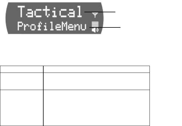
Check or Change Active Profile
If the Dwell Display is set to Profile, the screen will display the
user’s active profile at all times. Otherwise, to see the current
selection, use the Menu Selector keypad to access the Profile
Menu.
To switch to a new active Profile during your work shift, access
the Profile Menu from the Menu Selector keypad and make a
new selection from the options.
To Set your Active Profiles:
1. Use the Up and Down buttons to cycle through the Menu
choices until ProfileMenu appears.
2. Use the Left and Right buttons to cycle through the Profile
Menu options established by your Network Administrator.
Your selected Dwell Display will appear after a timeout of a few
seconds.
Figure 2-5: Profile Selection Menu
Table 2-6: Profile Selection Menu Components
COMPONENT
EXPLANATION
Profile Menu
Determines which group of up to 16
profiles will be your active Profile.
Menu Option
When you access the Menu, the
currently selected Active Profile
appears in the option line. To change,
scroll to a new Profile and press the
Select button.
Menu Option:
Sample Profile from your
Personality Dwell Display
Active Menu:
Profile Selection
27
Check or Change Active Talkgroup
1. Use the Up and Down buttons to cycle through the Menu
choices until TalkGrpMenu appears.
2. Use the Left and Right buttons to cycle through the list of
user groups in your Active Profile, as established by your
Network Administrator.
3. Press the Select button to lock in your choice.
Your selected Dwell Display will appear as soon as the CS-803
accepts your choice.
Figure 2-6: Talkgroup Selection Menu
Table 2-7: Talkgroup Selection Menu Components
COMPONENT
EXPLANATION
Talkgroup
Menu
Determines which group of up to 16
user groups will be your active
Talkgroup.
Menu Option
When you access the Menu, the
currently selected Active Talkgroup
appears in the option line. To change,
scroll to a new Talkgroup and press the
Select button.
Menu Option:
Sample Talkgroup from
your Dwell Display
Active Menu:
Talkgroup Selection

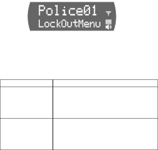
2.1.4 Lock Out Talkgroup
There are at least two ways to focus your voice communications
by suppressing calls from user groups in your active profile.
• No Scan. By changing your Scanning Mode to NOSCAN
means, you only scan your selected Talkgroup.
• Lock Out. By locking out selected Talkgroups, you can
eliminate just the background “noise” you select, focusing
your scanning resources on just the groups whose calls you
wish to track.
Groups You Can Lockout
• Active Profile. It stands to reason that only groups in your
active profile can be locked out, since they are the only
groups whose voice calls you will hear. You can lockout any
group in your profile, not just active groups.
• Received Call Menu. If you do not find a name, you are
looking for in the Lockout menu, it is not in your active
profile.
2.1.4.1.1 How to Lock Out a Listen Group
1. Use the Up and Down buttons to cycle through the Menu
choices until LockOutMenu appears.
2. Your display screen shows LockOutMenu in the bottom line
and, in the top line, the name of a user group from your
active profile.
3. Use the Left and Right buttons to cycle through the list of
candidates, if any, until the user group you want to Lock Out
appears onscreen.
4. Press the Select button to lockout the group. A < will
appear next to the name.
Your selected Dwell Display will appear as soon as the CS-803
accepts your Lockout choice.
29
2.1.4.1.2 How to Unlock a Listen Group
1. Use the Up and Down buttons to cycle through the Menu
choices until LockOutMenu appears.
2. Your display screen shows LockOutMenu in the bottom line
and, in the top line, the name of a user group from your
active profile.
3. Use the Left and Right buttons to cycle through the list of
candidates, if any, until the user group you want to Unlock
appears onscreen.
4. Press the Select button to unlock the group. The < will
disappear from next to the name.
Your selected Dwell Display will appear as soon as the CS-803
accepts your Unlock choice.
Table 2-8: Lockout Selection Menu
COMPONENT EXPLANATION
Menu Option
As you scroll through the user
groups in your active profile, notice
they only appear in the Lock Menu if
they are in the current profile.
Lock Out
Talkgroup Both Locked-Out and Not-Locked
groups appear in the Menu. The
locked-out group has a < next to the
name.
Caution Regarding Profile Changes
Talkgroup Lockout status does not survive a change of Profile. If
you need to select a new Profile after taking the time to Lockout
several Talkgroups from your current profile, understand that
making the change will unlock all groups.
• Compare your options before changing your profile. If you
can achieve your goal by temporarily assigning Priority
Talkgroup status to a user group, you may be able to avoid
having to lock out the same groups twice.

2.1.5 Select Scan Mode
Two scanning modes are available for the CS-803, but only one
can be active at any time. Changing your scanning mode
changes the way your control station scans voice calls for all of
the profiles in your user personality, no matter which profile is or
becomes active.
Your choice of scanning mode will broaden or narrow the span of
your communications with all the listen groups in your profiles,
but does not affect your interaction with your talk groups.
Your scanning mode choice will stay in effect until you change it
again; even if you turn off your radio, your current selection will
be saved until your next use.
Table 2-9: Scan Modes
Scan Mode Explanation
No Scanning
Eliminates distractions.
Full communications (listen and talk)
with your talk group.
No calls from listen groups.
Normal
Scanning
This is the default setting. Network
administrator has established this as
the most effective configuration for
everyday use.
Full communications (listen and talk)
with your talk group.
Receive calls from the listen groups,
if available from your current site.
31
Check or Change Active Scan Mode
The Dwell Display screens do not show active Scan Mode
status. To see your current selection, use the Menu Selector
keypad to access the Scan Mode Menu. The scan mode status
displayed in the top line of the screen display is your active
status.
To change scan mode during your work shift, access the Scan
Mode Menu from the Menu Selector keypad and make a new
selection from the options available.
• To narrow your scanning list to just the talk group in your
active profile, choose No Scan from the Scan Menu.
• To select the default scanning mode that scans all the
listen groups in your active profile, choose Normal from the
Scan Menu.

2.1.5.1.1 How to set your Scan Mode
1. Use the Up and Down buttons to cycle through the Menu
choices until ScnModeMenu appears.
2. Use the Left and Right buttons to cycle through the list
modes until your choice appears: Normal or No Scan.
3. Press the Select button to lock in your choice.
Your selected Dwell Display will appear as soon as the CS-803
accepts your choice.
Component Explanation
Scan Mode Menu
Determines whether you will scan
or suppress your listen groups for
incoming voice messages.
Menu Option
When you access the Menu, the
currently active Scan Mode
appears in the option line. To
change, scroll to a new mode and
press the Select button.
2.1.5.1.2 Duration of Scanning Mode Selections
Scanning Mode selections survive Power Down. At startup, your
radio will default to the scanning mode of your last use. Any
selection you make during your shift will remain in effect until you
make a new selection from the Scan Mode menu.

33
2.1.6 Emergency Communications
Your control station can send out an Alert or place Voice Calls
over the entire network in an emergency. OpenSky handles
Emergency Calls and Alerts with the very highest priority, giving
you and the people you serve access to the help you need no
matter how much traffic the network is handling.
How to Place an Emergency Call
1. Press the red Emergency Button on your user interface to
send an emergency alert. You will find the button just to the
right of the 5-button Menu and Selector keypad.
2. You will hear the emergency tone if you are successful.
Other users will hear the Emergency Alert signal, a
distinctive 3-tone burst of sound.
3. At the same time, the network enables the Emergency
Talkgroup provisioned in your current talkgroup.
4. The microphone is opened for a programmed amount of time
in order to send your voice out over the emergency talk
group.
5. Based on your provisioned priorities, the radios in the
Emergency Talkgroup will hear your call and see the
emergency talk group displayed on their radio.
6. When your emergency ends or if you inadvertently pressed
the button, press and hold the red Emergency Button a
second time to clear the emergency alert and call. Only you,
the user who initiated the alert, dispatcher, or the network
administrator can clear an emergency.

2.1.7 Selective Call
Selective calling is the capability for two voice radio units/control
stations to shortly obtain and utilize an independent talkpath for a
private call.
In the OpenSky system, a source control station can be
configured to initiate selective calls through a preprogrammed list
in memory. Alternatively, a properly equipped source control
station can initiate a selective call to any radio in the system by
entering the ten-digit voice user ID (which looks like a telephone
number) of the target device. Radios can optionally be
configured to only receive (not initiate) selective calls.
How to Make a Selective Call
1. Use the keypad to key trailing unique digits to place the call
OR, if you do not have a keypad, use the Up and Down
buttons to cycle through the Menu choices until Speed Dial
appears.
• If using the keypad mic, press the number.
• If using the Menu, select the number using the Left or Right arrows
and press Select.
2. If someone is calling you, you will hear a ringing sound.
Press the Right arrow to accept the call.
3. To hang-up, press the Select button.

35
2.1.8 Dynamic Regrouping
In the event of an emergency, the network administrator will
determine what control station/radio users should be formed into
an ad hoc talk group to respond to the emergency conditions.
The administrator will edit the personalities of the affected users
to include an emergency profile and then page the affected
control stations/radios (not users) to re-register with the network
to receive their edited personalities.
In response, affected control stations/radios automatically re-
register to receive their edited personalities.
During re-registration, subscriber equipment will default to the
profile selected by the administrator.
2.2 Operation with the TRCM-103 and
Third Party Tone Remote Desk Set
2.2.1 How to turn the Control Station/TRCM-103
on
1. Ensure the TRCM-103 has been installed in the back of the
CS-803 and calibrated with the Desk Set as indicated in the
Installation Manual.
2. Push the Power Switch on the rear panel of the CS-803.
An LED on the front of the CS-803 will illuminate to indicate
Power Up.
3. Power Up the Desk Set as directed by the Third Party Desk
Set’s user manual.
4. Wait through the Startup Sequence, which lasts
approximately 10 seconds.
During this time your control station is provisioned with your
customized user personality, emergency conduct and user
specifications, all designed for your specific needs by the
Network Administrator and prompted by your User ID.
2.2.2 How to Log on to the Network
Network log-on is either automatic or directed via a PC. Even if
you want to use your control station for non-network traditional
RF communications, you will still need to log on to the network
first, then select Talkaround Mode to work off-network.
Contact your local administrator for procedures on how to log
onto the Network.
CS-803
Power
Switch

37
2.2.3 Self-Test
After Power Up, your CS-803 control station undergoes a multi-
function automatic Boot procedure. Your control station is
provisioned with your user personality: as many as 16 user
profiles are downloaded to your equipment from the network in
response to your User ID. Emergency behavior is provisioned
along with each profile.
Your control station conducts a diagnostic Built-In Self-Test
(BIST). The Self-Test is a battery of hardware diagnostic tests on
the internal components of the control station. All processor and
memory elements, interfaces, connectivity elements, and RF
functionalities are diagnosed for operational integrity.
2.2.4 How to Turn the Control Station/TRCM-103
Off
1. Push the Power Switch on the rear panel of the CS-803.
The LED on the front of the CS-803 will cease to illuminate
to indicate Power Down.
2. Several user-selected radio settings will survive the Power
Down procedure.
3. At your next Power Up, these saved settings will
automatically default, along with your network personality
settings.
2.2.5 How to Change the Volume
See the Third Party Desk Set’s User Manual for changing the
volume setting.

2.2.6 Voice Calls
As soon as your control station completes the Startup/Log
On/Provision/Self-Test sequence and registers on the OpenSky
network, you will begin to hear voice calls from the talk and listen
groups in your active profile, if they are available.
How to Receive a Voice Call
No action is required on your part. The incoming call will be
forwarded as clear audio to the third part Tone Remote Desk
Set.
How to Make a Voice Call
The steps for making a voice call with your CS-803 are similar to
those for a conventional radio.
1. First, if you have not already, Power Up your CS-803. (See
Section 2.2.1).
2. Select the proper function button on the Third Party Tone
Remote Desk Set that corresponds to the Talk Group. See
your System Administrator for the mapping of Function
Buttons.
3. Depress and hold the transmit button on your Third Party
Tone Remote Desk Set.
4. Release the transmit button to terminate your outgoing voice
call.
2.2.7 Radio Tones
The control station user interfaces provides four (4) tones that
provide feedback to the user indicating whether the control
station is able to transmit on the channel when the Transmit
Button is pressed. These are described in the sections below.
39
• Deny Tone
If the control station is not able to access the channel, the control
station user interface will issue three short beeps, all of the same
pitch, as the deny indication. The control station user interface
will issue the deny tone if it is out of coverage, or if the requested
voice group is already active. The user must release the
Transmit button and re-key the Transmit button to make another
call request.
• Queued Tone
If the radio site is currently fully occupied with calls, a new call
request may be queued by the system. The control station
issues three tones, a low tone followed by two higher tones, to
indicate that the call has been placed in the queue. The user
may release transmit button at this point, if desired. When
resources are available, the user will receive the grant tone, and
the control station will begin to transmit once the transmit button
is re-keyed. The Transmit button should be released when the
talk spurt is complete.
• Grant Tone or Go-Ahead Tone
If granted after being queued, the control station user interface
provides a short single tone “beep” to inform the user that
channel access has been granted. The user should press and
hold the Transmit button, and begin speaking.
• Removed Tone
After access to the control station channel has been granted and
the user is transmitting, the control station may be pre-empted by
a high priority call or by loss of coverage. The removed tone is a
single long low-pitched tone, which notifies the user that access
to the channel has been lost. When the removed tone is heard,
access to the channel has been lost and the control station is no
longer transmitting, even if the Transmit button is being pressed.
The Transmit button must be re-keyed to regain channel access.
M/A-COM, Inc.
1011 Pawtucket Boulevard
Lowell, MA 01853
1-877-OpenSky/978-442-5000
Fax: 978-442-5350
www.macom.com