User Manual

Installation Manual
MM102424V1 R1A
Data Brick DB800

2
The software contained in this device is copyrighted by M/A-COM, Inc.
Unpublished rights are reserved under the copyright laws of the United
States.
NOTICE!
This manual is published by M/A-COM, Inc. without any warranty.
Improvements and changes to this manual necessitated by typographical
errors, inaccuracies of current information, or improvements to programs
and/or equipment, may be made by M/A-COM, Inc. at any time and
without notice. Such changes will be incorporated into new editions of this
manual. No part of this manual may be reproduced or transmitted in any
form or by any means, electronic or mechanical, including photocopying
and recording, for any purpose, without the express written permission of
M/A-COM, Inc.
Copyright © 2003, M/A-COM, Inc. All rights reserved.

3
TABLE OF CONTENTS Page
1. SAFETY..............................................................4
1.1 MPE LIMITS ............................................4
1.2 SAFETY TRAINING INFORMATION...5
1.3 TRANSMITTER HAZARDS ...................6
1.4 OPERATING TIPS...................................9
1.5 OCCUPATIONAL SAFETY GUIDELINES....9
2. PRODUCT DESCRIPTION ...........................11
3. SPECIFICATIONS..........................................12
3.1 GENERAL ..............................................12
3.2 TRANSMITTER.....................................12
3.3 RECEIVER .............................................13
3.4 DIGITAL OPERATION .........................14
3.5 REGULATORY DATA..........................14
4. OPTIONS AND ACCESSORIES...................15
5. INSTALLATION.............................................16
5.1 POWER INSTALLATION.....................16
5.2 ANTENNA INSTALLATION................17
6. CONFIGURATION.........................................18
7. MOUNTING REQUIREMENTS...................19
8. TROUBLESHOOTING ..................................20

4
1. SAFETY
1.1 MAXIMUM PERMISSIBLE EXPOSURE
(MPE) LIMITS
Do not transmit with this radio and antenna when persons
are within the MPE Radius of the antenna, unless such
persons (vehicle occupants or bystanders, for example) are
shielded from the antenna field by a metallic barrier (such
as the user’s vehicle rooftop). The MPE Radius is the
minimum distance from the antenna axis that ALL persons
should maintain in order to avoid RF exposure higher than
the allowable MPE level set by the FCC.
WARNING
Failure to observe these limits may
allow those within the MPE radius to
experience RF radiation absorption
which exceeds the FCC maximum
permissible exposure (MPE) limit. It
is the responsibility of the installer to
ensure that the maximum permissible
exposure limits are observed at all
times during radio transmission. The
installer is to ensure that no
bystanders come within the radius of
the maximum permissible exposure
limits shown below.
5
1.1.1 Determining MPE Radius
The Maximum Permissible Exposure Radius has been
estimated to be a radius of about 6.3 inches (or 16 cm) for a
5 dBi gain antenna, and 11.25 inches (or 28.5 cm) for a 10
dBi gain antenna per OET bulletin 65 of the FCC. This
estimate is made using the maximum capable power of the
radio and a maximum 50% transmit duty cycle.
1.2 SAFETY TRAINING INFORMATION
WARNING
The DB800 generates RF
electromagnetic energy during transmit
mode. This radio is designed for and
classified as “Occupational Use Only”
meaning it must be used only during the
course of employment by individuals
aware of the hazards and the ways to
minimize such hazards. This radio is
NOT intended for use by the “General
Population” in an uncontrolled
environment. It is the responsibility of
the installer to ensure that the
maximum permissible exposure limits
are observed at all times during radio
transmission. The installer is to ensure
that no bystanders come within the
radius of the maximum permissible
exposure limits.

6
This radio has been tested and complies with the FCC RF
exposure limits for “Occupational Use Only.” In addition,
this M/A-COM radio complies with the following Standards
and Guidelines with regard to RF energy and
electromagnetic energy levels and evaluation of such levels
for exposure to humans:
• FCC OET Bulletin 65 Edition 97-01 Supplement C,
Evaluating Compliance with FCC Guidelines for
Human Exposure to Radio Frequency Electromagnetic
Fields.
• American National Standards Institute (C95.1 – 1992),
IEEE Standard for Safety Levels with Respect to
Human Exposure to Radio Frequency Electromagnetic
Fields, 3 kHz to 300 GHz.
• American National Standards Institute (C95.3 – 1992),
IEEE Recommended Practice for the Measurement of
Potentially Hazardous Electromagnetic Fields – RF and
Microwave.
1.3 TRANSMITTER HAZARDS
WARNING
The installer should be aware of
certain hazards common to the
operation of vehicular radio
transmitters. A list of several possible
hazards is given:
7
1. Explosive Atmospheres – Just as it is dangerous to
fuel a vehicle with the motor running, similar hazards
exist when operating a vehicular radio. Be sure to turn
the radio off while fueling a vehicle. Do not carry
containers of fuel in the trunk of a vehicle if the radio is
mounted in the trunk.
Areas with potentially explosive atmospheres are
often, but not always, clearly marked. Turn OFF
your radio when in any area with a potentially
explosive atmosphere. It is rare, but not impossible
that the radio could generate sparks.
2. Interference to Vehicular Electronic Systems –
Electronic fuel injection systems, electronic anti-skid
braking systems, electronic cruise control systems, etc.,
are typical electronic systems that can malfunction due
to the lack of protection from radio frequency energy
present when transmitting. If the vehicle contains such
equipment, consult the dealer and enlist their aid in
determining the expected performance of electronic
circuits when the radio is transmitting.
3. Dynamite Blasting Caps – dynamite blasting caps
may be caused to explode by operating a radio within
500 feet of the blasting caps. Always obey the “Turn
Off Two-Way Radios” signs posted where dynamite is
being used.

8
When transporting blasting caps in a vehicle:
a) Carry the blasting caps in a closed metal box with a
soft lining.
b) Leave the radio OFF whenever blasting caps are
being put into or removed from the vehicle.
4. Liquefied Petroleum (LP) Gas Powered Vehicles –
mobile radio installations in vehicles powered by
liquefied petroleum gas with the LP gas container in the
trunk or other sealed-off space within the interior of the
vehicle must conform to the National Fire Protection
Association standard (NFPA) 58 requiring:
a) The space containing the radio equipment shall be
isolated by a seal from the space containing the LP
gas container and its fittings.
b) Outside filling connections shall be used for the LP
gas container.
c) The LP gas container shall be vented to the outside
of the vehicle.
WARNING
Under U.S. law, operation of an
unlicensed radio transmitter within the
jurisdiction of the United States may be
punishable by a fine of up to $10,000,
imprisonment for up to two years, or
both.

9
1.4 OPERATING TIPS
The following conditions tend to reduce effective range and
should be avoided whenever possible.
• Operating the radio in areas of low terrain, or while
under power lines or bridges.
• Obstructions such as mountains and buildings.
• In areas where transmission or reception is poor, some
improvement may be obtained by ensuring that the
antenna is vertical. Moving a few yards in another
direction or moving to a higher elevation may also
improve communication.
1.5 OCCUPATIONAL SAFETY GUIDELINES
AND SAFETY TRAINING INFORMATION
CAUTION
To ensure that exposure to RF
electromagnetic energy is within the FCC
allowable limits for occupational use,
always adhere to the guidelines below.
The DB800 can transmit using a replaceable antenna. When
the radio is ON, it receives and also transmits radio
frequency (RF) signals. In order to maintain registration, the
radio periodically transmits, even when the PTT switch has
not been pressed.
10
In 1996, the Federal Communications Commission (FCC)
adopted RF exposure guidelines with safety limits for
portable devices, based on the recommended limits of the
National Council on Radiation Protection and
Measurements (NCRP) and the American National Safety
Institute (ANSI).
The design of the DB800 complies with the FCC guidelines
for Occupational / Controlled exposure to RF
electromagnetic fields. To assure optimal performance and
make sure human exposure to RF electromagnetic energy is
within the FCC guidelines, always adhere to the following:
1. The DB800 should only be used for necessary work
related communications.
2. The DB800 should only be used by authorized and
trained personnel and should not be operated by
children.
3. Do not attempt any unauthorized modification to the
DB800. Changes or modifications CAN cause harmful
interference. Service of the DB800 should only be
performed by qualified personnel.
4. Always use M/A-COM authorized accessories
(antennas, etc.). Use of unauthorized accessories can
cause the FCC RF exposure compliance requirements
to be exceeded.
11
2. PRODUCT DESCRIPTION
The DB800 is a digital radio housed in a metal casting,
whose function is to send data communication. The Data
Brick can transmit information such as position, traffic
flow, or atmospheric conditions. Three mounting holes are
provided to attach the DB800 to an indoor wall or post or to
mount inside an enclosure for outdoor use. The DB800 is
also suitable for vehicle mounting.
The DB800 operates in OpenSky Trunked Protocol (OTP)
mode and supports voice grouping, priority scanning, pre-
emptive emergency calls, late call entry, and dynamic
reconfiguration. It performs autonomous roaming for wide
area applications.
Features and user profiles for DB800 are software-defined
and can be reprogrammed over the air. This feature allows
communications protocols to be changed and added at any
time.
12
3. SPECIFICATIONS
3.1 GENERAL
Dimensions without
Antenna (H x W x D): 6.2 x 4.3 x 1.4 in.
(158 x 110 x 36 mm)
Weight: 22.5 oz (635g)
Input Voltage: 8.5 VDC ± 20%
Operating Temperature
Range: -22 to +140°F
(-30 to +60°C)
Relative Humidity: 95% (Non-Condensing)
@ 140°F (+60°C)
Altitude (Operational): 15000 ft (4572 m)
Color (Case): Metallic
3.2 TRANSMITTER
800
Frequency Range (MHz): 806-824
Rated RF Power (W): 5.5 Watts typ.
Frequency Stability
(-30 to +60°C) (ppm): ±1.5
Modulation Deviation (kHz): 4.5 FM
4.5 OTP
13
Audio Response (dB): +1/-3
Spurious and Harmonics
(dBm): Meets FCC Part 90,
emission mask “G” and “H”
Audio Distortion: <3% at rated audio @
1000 Hz, 3 kHz deviation
3.3 RECEIVER
800
Frequency Range (MHz): 851-870
Channel Spacing (kHz): 12.5, 25, PLL Step
FM Hum and Noise (dB): >35
Analog Sensitivity (12 dB
SINAD, TIA/EIA-603)
(dBm):
-118
Digital Sensitivity (5%
block error rate, OpenSky
protocol, AWGN) (dBm):
-110
Selectivity @ 25 kHz (dB): >63
Intermodulation (dB): >70
Spurious and Image
Rejection (dB): >70
Frequency Stability (-30 to
+60°C) (ppm): ±1.5
Rated Audio Output (mW): 500 @ <3% max distortion
14
3.4 DIGITAL OPERATION
Vocoding Method Advanced MultiBand
Excitation (AMBE™)
Data Rate 19.2 kbps
Modulation 4-Level GMSK
3.5 REGULATORY DATA
Frequency Range (MHz) 806-824 (TX)
851-870 (RX)
RF Output (W) 6
Frequency Stability (ppm) 1.5
FCC Type Acceptance No: BV8DB800
Applicable FCC Rules 15, 90
Industry Canada
Certification No: 3636DB800
Applicable Industry
Canada Rules RSS-119

15
4. OPTIONS AND ACCESSORIES
MODEL/OPTION
NUMBER DESCRIPTION
Transceiver*
MAHROS0047 DB800, 800 MHz
Antennas*
MAHROS0024 Antenna, 800MHz, Elevated
Feed, Mobile
MAHROS0093 Antenna, 800MHz, Tower
Top, Fixed
Optional Features
OS-P25 P25 Common Air Interface
OS-ENC Voice Encryption
MAHROS0039 Over-the-Air Rekeying
(requires encryption to be
purchased)
16
5. INSTALLATION
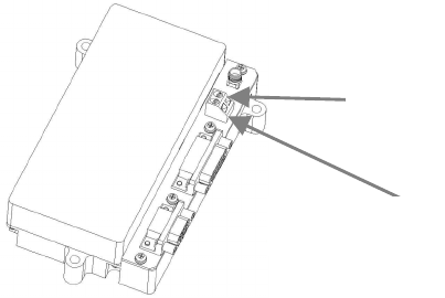
5.1 POWER INSTALLATION
Insert a stripped wire, (14-22 AWG) into the +8.0 VDC
connector on the left side of the power connector. Insert a
stripped wire, (14-22 AWG) into the GND connector on the
right side of this connector. Secure the wires in the Data
Brick connector by tightening the screws with a small
Phillips screwdriver. The other end of power wire should be
connected to an +8.0 VDC source. The other end of the
ground wire should be connected to the negative terminal.
The DB800’s operating voltage is 7.0 to 8.5 VDC.
Exceeding this voltage can permanently damage the device.
Figure 5-1: Power Installation
GND
+8.0 VDC
17
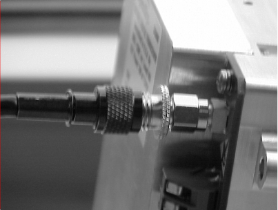
5.2 ANTENNA INSTALLATION
Screw the antenna into the connector on the top of the
DB800 by turning it clockwise into the SMA connector.
Figure 5-2: Antenna Wire Connector Installed
18
6. CONFIGURATION
Configuration of the DB800 is performed with an external
computer attached to the DB9 port on the Data Brick. The
Network Administrator will configure the DB800. Changes
to the configuration, if required, can be made by the
Network Administrator over the air if this option has been
purchased.
19
7. MOUNTING REQUIREMENTS
The DB800 can be mounted in a fixed or mobile setting
indoors or outdoors It should always be mounted in an
environmentally controlled area. See 3. SPECIFICATIONS
for environmental requirements.
Outdoors, the DB800 should be mounted in a customer-
supplied enclosure that can supply the required voltage as
well as the appropriate environmental conditions.
Indoors, the DB800 can be mounted using the mounting
holes on the housing in areas of appropriate environmental
conditions.
The DB800 should not be mounted less than 3 feet from
human traffic.
In vehicles, the DB800 should be mounted in an enclosure
in the trunk or inside the vehicle but more than 3 feet from
where occupants may be riding.
20
8. TROUBLESHOOTING
If troubleshooting assistance is required, contact a qualified
service technician or call M/A-COM at 1-877-673-6759.
21
WARRANTY
DROP IN

M/A-COM, Inc.
1011 Pawtucket Boulevard
Lowell, MA 01853
1-877-OpenSky/978-442-5000
www.macom.com Printed in U.S.A.