User Manual

198 17-HRC104 201 PA9 © 1999 Ericsson Inc. - All Rights Reserved
User Manual
PA9
Mobile Advantage Wireless Office
(DWOS 1.0)
User Manual

User Manual—Mobile Advantage Wireless Office (DWOS 1.0)
2(80) 198 17-HRC104 201 PA9
The contents of this document are subject to revision without notice due to
continued progress in methodology, design, and manufacturing.
Ericsson Inc. must have no liability for any errors or damages of any kind re-
sulting from the use of this document.

User Manual—Mobile Advantage Wireless Office (DWOS 1.0)
198 17-HRC104 201 PA9 3 (80)
Contents
1 Introduction 6
1.1 About This Manual 6
1.2 Revision History 6
1.3 How To Use This Manual 7
2 System Description 8
2.1 Overview 8
2.2 Mobile Advantage Mobile Phone User Features 9
2.3 Mobile Advantage Connections 12
2.4 Mobile Advantage Unit Descriptions 14
2.4.1 Mobility Server 14
2.4.2 Cellular Radio Exchange (CRE) 15
2.4.3 Radio Heads (RH) 18
2.4.4 Scanners 18
2.4.5 Mobile Advantage Mobile Phones 18
3 Site Planning 19
3.1 Site Capacity and Reliability 19
3.2 Mobility Server Planning 19
3.2.1 Mobility Server Connections 20
3.3 Cellular Radio Exchange (CRE) Planning 20
3.3.1 CRE connections 21
3.4 RH Planning 22
3.4.1 Estimating Radio Coverage 22
3.4.2 RH Connections 23
3.5 Scanner Planning 23
3.5.1 Scanner Connections 23
4 Site Preparation 24
4.1 Environmental Requirements 24
4.2 Power Requirements 24
4.3 RH and Scanner Cable Installation 25
4.3.1 Installing Cables From The CRE to RHs or Scanners 25
5 Installation 27
5.1 Dangers, Warnings, and Cautions 27
5.1.1 Protection against Electrostatic Discharge (ESD) 27
5.2 Installing RHs or Scanners 28
5.3 Installing the Mobile Advantage Mobility Server 28
5.4 Installing a Cellular Radio Exchange (CRE) 29
5.4.1 Installing a single-cabinet (main) Wall-Mounted CRE 30
5.4.2 Installing a two-cabinet (Main and Auxiliary) Wall-Mounted CRE
32
6 Integration and Test 36
6.1 Integration 36
6.1.1 Initial frequency selection 36

User Manual—Mobile Advantage Wireless Office (DWOS 1.0)
4(80) 198 17-HRC104 201 PA9
6.1.2 Mobile Advantage Initialization 36
6.1.3 The ANSI-41 Link to the HLR 37
6.2 Post-Installation test 37
7 Numbering Plans 39
7.1 Examples of number usage 40
8 Operations, Administration and Maintenance (O&M)
42
8.1 Overview 42
8.1.1 Configuration Management 42
8.2 O&M User Interface 42
8.2.1 User Login 42
8.2.2 Examples of O&M interface screens 43
8.3 Description of Authorities 44
8.3.1 Access Rights 44
8.4 Service Areas 45
8.4.1 Customer 45
8.4.2 End User 46
8.4.3 Personal Number services 47
8.4.4 Route Handling 47
8.4.5 Hardware Resources 47
8.4.6 Fault Management 47
8.4.7 Number Analysis 48
8.4.8 System Network 48
8.4.9 Call Logging 48
8.4.10 Performance 48
8.4.11 Security 48
8.4.12 Tools 48
8.4.13 System Description 48
8.4.14 Security Management 48
9 Troubleshooting 50
9.1 General 50
9.1.1 Start and restart 50
9.1.2 System Backup 50
9.2 Fault Management 50
9.3 Other fault indicators 51
9.3.1 RH and Scanner LEDs 52
9.3.2 CRE Boards Common LEDs 52
9.3.3 DTU Board LEDs 53
9.3.4 SPU Boards LEDs 53
9.3.5 RLU Boards LEDs 53
9.3.6 SWB LEDs 53
10 Software and Hardware Upgrades 54
10.1 Hardware Upgrades 54
10.2 Upgrading From a One-Cabinet to a Two-Cabinet
System 55
10.3 Software Upgrades 57

User Manual—Mobile Advantage Wireless Office (DWOS 1.0)
198 17-HRC104 201 PA9 5 (80)
11 Appendix A—Cabling and Connectors 58
11.1 Overview 58
11.2 -48 Vdc Power and Ground Cables 59
11.2.1 -48 Vdc Power Cables 59
11.3 Backplane Interconnect Cable for a Two-Cabinet CRE
59
11.4 RLU Ethernet Interface Cable (Slot Three Only) 60
11.5 RLU Connections 60
11.5.1 Punch Block to Radio Heads (RH) or Scanners Cabling 60
11.6 SwitchBoard (SWB) 66
11.6.1 SWB Ethernet Interface 66
11.6.2 SWB E1/T1 PCM Interface 67
11.6.3 SWB to DTU cables 71
12 Appendix B—Acronyms and Abbreviations 72
13 Appendix C—Mobile Advantage Unit Specifications
77
13.1 Mobility Server 77
13.2 CRE Specifications 77
13.2.1 CRE Cabinet Dimensions 77
13.2.2 CRE Configuration Example 77
13.2.3 CRE Board Assignments 78
13.3 Radio Heads and Scanners 78
13.4 System power requirements 79
14 Appendix D—Recommended tools 80
14.1 General 80

User Manual—Mobile Advantage Wireless Office (DWOS 1.0)
6(80) 198 17-HRC104 201 PA9
1 Introduction
1.1 About This Manual
This user manual describes how to plan, install, configure, test, operate and
maintain the Ericsson Mobile Advantage™ Wireless Office. Sections in this
manual explain the hardware and software building blocks and the general
specifications for the Mobile Advantage system.
This manual is developed and maintained in printable form and filtered into
HyperText Markup Language (HTML) outputs suitable for Internet
publication, printing, and CD-ROM delivery. In print format, acronyms and
abbreviations are expanded when first used. All acronyms and abbreviations
are explained in “Appendix B—Acronyms and Abbreviations”, on page 72.
In the HTML format, all acronyms and abbreviations are hyper-linked to the
appendix and references are linked to the sources.
General information for the configuration and use of TDMA-136 compatible
mobile phones that function within the Mobile Advantage environment is
provided in this manual. More specific information about compatible
products can be obtained on-line on the Ericsson WEB page.
Writer’s Note:This document will contain generic specifications for the
TDMA-136 mobile phones as well as a generic description
of how to program a phone for use in DWOS. In the
HTML version, there should be a link to the Ericsson
WEB site that contains more specific information.
1.2 Revision History
PA1—Chapters one through three are included in release PA1 for review.
Other chapters are in progress but all information is not deemed reliable at this
time. Other releases will be issued shortly.
PA2—Chapters one through three updated with specification data for tables.
Chapters four and five in progress, Index for cables is in review. (10/27/98).
PA3—Chapters one through three updated after review on 10-30-98,
Appendix A updated and reviewed.
PA4—Removed references to rack-mounted cabinet. Combined sections on
Post Installation test and Integration and Test. Added version 2 (all software
loaded at factory) in Installation section. Added Appendices B, C, D.
PA5—In progress—Editing Troubleshooting section, Recommended Tools.
PA6—All edits included, rewrite of O&M section.
PA7—Contents from formal review conducted 12-04-98 included.
PA8—Includes changes since 12-04-98 formal review.
PA9—Additional updates from 01-06-99 meeting.

User Manual—Mobile Advantage Wireless Office (DWOS 1.0)
198 17-HRC104 201 PA9 7 (80)
1.3 How To Use This Manual
To effectively use this manual, personnel should be certified by Ericsson in
the planning, installation, or operation and maintenance (O&M) of the Mobile
Advantage system. This manual provides support and reference material for
personnel performing the following functions:
•Mobile Advantage Supplier (System Supplier)—The Mobile Advantage
Supplier plans, delivers, and installs the Mobile Advantage system. The
Mobile Advantage Supplier provides the help desk function to the Mobile
Advantage Operator for analysis of system faults and system upgrades.
•Wireless Operator—The Wireless Operator owns the frequencies used by
Mobile Advantage. The Wireless Operator maintains the Mobile
Advantage user information in the Public Land Mobile Network (PLMN)
HLR. The Wireless Operator can also view and change the frequencies
used by Mobile Advantage.
•Mobile Advantage Operator (System Operator)—The Mobile Advantage
Operator maintains the Mobile Advantage system. The Mobile
Advantage Operator manages O&M functions such as fault and
performance monitoring, configuration, security, and accounting
management.
•Mobile Advantage User Administrator (System Administrator)—The
Mobile Advantage User Administrator manages the Mobile Advantage
user profiles, the addition or deletion of Mobile Advantage users or
changing the user profiles.

User Manual—Mobile Advantage Wireless Office (DWOS 1.0)
8(80) 198 17-HRC104 201 PA9
2 System Description
2.1 Overview
Mobile Advantage functions as an extension of wired communication
systems with additional mobile capabilities. Wireless systems provide the
same services as most commonly used Private Branch Exchange (PBX), with
the advantage of portable telephone capabilities. Mobile Advantage extends
normal mobile systems functions to operate inside buildings, factories, and
other internal sites.
Mobile Advantage mobile phones operate in either the 850 MHz (Cellular) or
1900 MHz Personal Communications Service (PCS) bands. To function in the
Mobile Advantage environment, mobile phones must be compatible with the
TDMA-136 standard protocol and have Adaptive Code Excited Linear
Prediction (ACELP) speech capability. ACELP is a speech coding and
decoding standard for mobile phones. For more information about the
TDMA-136 standard see “Appendix B—Acronyms and Abbreviations”, on
page 72.
Mobile Advantage users within the Mobile Advantage area use a private
numbering plan for calls to other Mobile Advantage users. Mobile Advantage
users communicate with public telephones through a PBX link connected to
the Public Switched Telephone Network (PSTN).
Mobile Advantage is associated with the Public Land Mobile Network
(PLMN) where the users are defined as standard cellular or PCS subscribers
in a Home Location Register (HLR). The subscription of users with the
PLMN allows Mobile Advantage users to roam outside the Mobile Advantage
area as normal cellular phones. The PLMN and the Mobile Advantage
authenticate mobile phone users by accessing an HLR connected to the
Common Channel Signaling System Number 7 (SS7) Network. To access the
HLR, Mobile Advantage is connected to the SS7 Network through a WOS
(Wireless Office System) SS7 Gateway link.
The associated PLMN notifies Mobile Advantage when a user is roaming in
the network. Mobiles entering or initializing in the system area notify Mobile
Advantage with a Private System Identification (PSID). Only mobile phones
defined to the Mobile Advantage system can function fully within a Mobile
Advantage environment.
Mobile Advantage can be configured to accept and transfer emergency calls,
such as E911 calls, from any mobile phone operating within the Mobile
Advantage coverage area. The mobile phone making the emergency call must
be compatible with TDMA-136 standard protocol and have ACELP speech
capability.
Mobile Advantage Operations, Administration, and Maintenance (O&M)
functions are performed through World Wide Web (WWW) or host
connections. The O&M Client application allows Mobile Advantage System
Administrators to receive operational information and administer the system
remotely.
The major physical components of the Mobile Advantage system are as

User Manual—Mobile Advantage Wireless Office (DWOS 1.0)
198 17-HRC104 201 PA9 9 (80)
follows:
•Mobility Server—The Mobility Server is a commercial server running
Ericsson open and scalable software on the Windows NT 4.0 operating
system. The Mobility Server connects to the Cellular Radio Exchange
(CRE) for configuration and administration of the Radio Infrastructure
(RI) and real-time tasks such as call switching.
The Mobility Server also provides the interfaces to the WOS SS7 Gateway
and the Internet. The bearer for both interfaces is Transport Control
Protocol/Internet Protocol (TCP/IP). The protocol to the SS7 network is
ANSI-41 Rev D.
•Cellular Radio Exchange (CRE)—The CRE, directed by the Mobility
Server, provides the physical interface between mobile phones in the
system area and the external PSTN through PBX links. Connections
between mobile phones operating in the system area are switched within
Mobile Advantage without accessing external networks. Mobile
Advantage supports the following PBX links:
-
T1 links to PBXs compatible with the Lucent Technologies 4ESS or
5ESS-2000 switch as specified in Lucent document 235-900-342.
-
T1 links compatibly with AT&T network-side Primary Rate
Interface (PRI) as specified in (TR 41 459) protocol.
-
Links to PBXs (for example, the Ericsson MD110) using the QSIG
protocol.
•Radio Heads (RH)—RHs connect to the CRE for communications with
Mobile Advantage mobile phones. RHs are placed at positions within the
Mobile Advantage area that provide maximum coverage and capacity.
Using multiple redundant RHs in an area will increase call handling
capabilities, as well as assuring continued call processing capabilities in
the event of a single RH unit failure.
•Scanners—Scanners also connect to the CRE and provide frequency
information for neighboring PLMN cells to Mobile Advantage.
Information obtained by Scanners is used by the system to minimize
interference from Mobile Advantage on PLMN frequencies.
•Mobile Phones—Mobile Advantage mobile phones are cellular or PCS
phones that are compatible with TDMA-136 standard protocol and
capable of ACELP speech encoding.
2.2 Mobile Advantage Mobile Phone User Features
Within the Mobile Advantage area, a registered user has access to the
following features:
•Personal Assistant (PA)—Allows the user the capability to change the
personal service profile. PA can be administered from any phone with
voice menus or through a WWW interface. If PA is administered from a
phone other than the user’s phone, a Personal Identification Number
(PIN) code must be entered.

User Manual—Mobile Advantage Wireless Office (DWOS 1.0)
10 (80) 198 17-HRC104 201 PA9
•Follow Me—Allows the user to control the transfer of call service.
Follow me consists of the following functions:
-
Follow Me Out—The user can select to receive or not to receive calls
placed to the user’s Direct In Dialing (DID) or DWOS User Number
(DUN), after the user leaves the system area and enters the PLMN.
-
Follow Me In—The user can select to receive or not to receive calls
placed to the user’s Mobile Directory Number (MDN) after the user
leaves the PLMN and enters the Mobile Advantage area.
•Call Screening—Allows the user to decide from whom to accept calls.
•Call Forwarding—Allows the user to forward incoming calls to other
terminals. The forwarding destination is determined by the Mobile
Advantage user’s current active profile.
•Caller’s Control—Allows the calling party to select a preferred
answering treatment from either a terminal or voice mail system.
•Three-Party Call Service—Allows a user to access Inquiry, Refer Back,
and Transfer features as follows:
-
Inquiry allows a user who is engaged in a two-party call to initiate a
call to a third party.
-
Refer Back allows the controlling party engaged in a three-party call
to switch between the active line and the held line.
-
Call Transfer allows the controlling party in a three-party call to
transfer the call to the other users and disconnect.
• Call Waiting—Notifies the user engaged in a two-party call that there is
an incoming call waiting. The user may do any of the following:
-
Disconnect the active call and accept the incoming call.
-
Place the active call on hold and accept the incoming call.
-
Ignore the incoming call. The incoming call will be forwarded to the
answering treatment defined with the PA.
•Calling Line Presentation and Restriction—Allows the calling number to
be presented to the user. If the calling party is a Mobile Advantage user
calling a Mobile Advantage user within the system area, the DUN is
presented. If the called party is outside the system area, the DID number
is sent. Mobile Advantage can be configured to substitute a general
number or restrict presentation of DID numbers.
•PBX Voice Mail—Allows calls to a user to be forwarded to the PBX
voice mail system. Mobile Advantage users can also use the voice
mailbox when roaming in the PLMN.
Note: It is recommended the PLMN mailbox not be active when using
the Mobile Advantage PBX Voice Mail service.
•Message Waiting Indicator (MWI)—Allows users of the PBX Voice
Mail system to be notified with a visual message waiting indicator.

User Manual—Mobile Advantage Wireless Office (DWOS 1.0)
198 17-HRC104 201 PA9 11 (80)
•Common Answering Position—Allows the Mobile Advantage
Administrator to define a common answering position destination to
forward all calls when a user is not available. The destination could be a
voice mail box or other service.
•Short Message Service (SMS)—Allows users in the Mobile Advantage
area to receive SMS messages delivered from the PLMN.
•Common Abbreviated Dialing—Allows the Mobile Advantage
Administrator to define a set of abbreviated numbers for all users.
•DTMF Generation—Allows users to generate Dual Tone
Multi-Frequency (DTMF) tones when calling.
•Concurrent Ringing—Allows simultaneous ringing of a user’s PBX
extension and mobile phone when a call is received within the Mobile
Advantage area.

User Manual—Mobile Advantage Wireless Office (DWOS 1.0)
12 (80) 198 17-HRC104 201 PA9
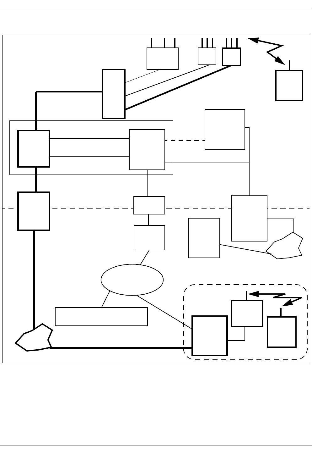
2.3 Mobile Advantage Connections
Operations and Maintenance (O&M) of the Mobile Advantage system can be
accomplished through Internet, Intranet, or local host connections. Figure 1
illustrates Mobile Advantage O&M and speech path connections. The PBX,
WOS SS7 Gateway, and Internet Gateway are connections to external
networks, not components of Mobile Advantage. The external networks,
represented below the dotted line, are shown for clarity. The bold line
indicates the speech path of a call placed by a mobile phone user within the
Mobile Advantage area to a user roaming in the PLMN.
User Manual—Mobile Advantage Wireless Office (DWOS 1.0)
198 17-HRC104 201 PA9 13 (80)
Figure 1 Mobile Advantage
RH
PSTN
CRE
Mobile
T1/E1
Cellular
External
Antenna
Mobile Advantage
Home Location Register (HLR) DWOS
Mobile
WOS SS7
Gateway
Switching
Center
SS7 network
ANSI-41
Mobility
Server
(SWB Control)
Internet
Gateway
10-BASE-T
Internet
Host
Connection
Mobile
Ethernet 10Base-T
TCP/IP
Ethernet
Scanner RH
Phone
(CRE O&M Interface)
Ethernet 10Base-T
Router
ANSI-41
Radio Link (RLINK)
WWW
O&M
Client
Interface
O&M
Interface
Phone
P
u
n
c
h
B
l
o
c
k
s
RS-232
Interface
PLMN
PBX
area
Mobile Advantage

User Manual—Mobile Advantage Wireless Office (DWOS 1.0)
14 (80) 198 17-HRC104 201 PA9
2.4 Mobile Advantage Unit Descriptions
2.4.1 Mobility Server
The Mobility Server is based upon a Pentium processor system with
redundant drives, fans and power supplies. A four-port Network Interface
Card (NIC), two serial ports, and an optional internal modem provide external
access and communications. The Mobility Server performs call control,
service control, and O&M functions in the Mobile Advantage system.
The Mobility Server is powered by redundant -48 Vdc power supplies.
Indications of loss of a single power supply, fan module, or hard drive, and
other failures are propagated to the Mobile Advantage Alarm Log and can be
configured to signal audibly.
The following redundant Mobility Server units can be hot swapped, which
means the Mobility Server does not have to be powered off to replace the
units:
•Hard drives
•Power supplies
•Fans
The following Mobility Server host interfaces can also be replaced without
powering off the Mobility Server:
•Keyboard
•Monitor
•Mouse
2.4.1.1 Mobility Server connections
The Mobility Server connects to the CRE with two Ethernet interfaces. The
following cables are supplied with the system:
•A reverse CAT 5 cable with RJ-45 connectors is the physical link from a
Mobility Server NIC port to the RLU board in slot three of the main
cabinet.
Note: A reverse CAT 5 cable is designed as a direct link between
Ethernet nodes. With a reverse CAT5 cable the receive (RXD)
and transmit (TXD) wire pairs are swapped.
•A reverse CAT 5 cable with RJ-45 connectors is also the physical link
from a Mobility Server NIC port to the SwitchBoard (SWB) in slots 10
and 11 of the main cabinet.
The Mobility Server supports the following external connections:
•A link to the WOS SS7 Gateway to access HLRs in the PLMN network—
The physical interface is standard CAT 5 cable between a Mobility
Server NIC port and a gateway in the SS7 network.

User Manual—Mobile Advantage Wireless Office (DWOS 1.0)
198 17-HRC104 201 PA9 15 (80)
•A link to the Internet or Intranet for O&M services— The physical
interface is a CAT 5 cable between a Mobility Server NIC port and the
Internet gateway.
2.4.2 Cellular Radio Exchange (CRE)
The Mobile Advantage CRE consists of a main cabinet or a main and one
auxiliary cabinet. The cabinets are identical and have 11 physical board slots
each. A CRE main and one auxiliary cabinet are required to support the
maximum simultaneous call capacity. In two-cabinet configurations, the
cabinets are interconnected with a ribbon cable between the backplanes.
Figure 2 is an example of a CRE main cabinet configuration.
2.4.2.1 CRE Connections
The CRE is connected to the Mobility Server with the two reverse CAT 5
Ethernet 10Base-T cables with RJ-45 connectors, supplied with the system.
The cables connect to the RLU board in slot three and the SWB in slots 10 and
11 of the main cabinet.
Note: A reverse CAT 5 cable is designed as a direct link between Ethernet
nodes. With a reverse CAT5 cable the receive (RXD) and transmit
(TXD) wire pairs are swapped.
Two internal E1 links connect the SWB to the Digital Traffic Unit (DTU)
board in the CRE. The SWB also has connections for a maximum of six
external E1 or T1 links to PBXs, Voice Mail, or other systems.
Two RLU telephony cables connect from all RLU boards to punch blocks.
CAT 5 cables connect from the punch blocks to the RHs and Scanners.
Note: Do not connect any RLU cables to the RLU board in slot three of the
main cabinet. The RLU board in slot three of the main cabinet does not
support links to the RHs or Scanners.
The CRE cabinets are individually powered by a -48 Vdc power source.
Power is supplied by cables connected to the CRE Power Module (CPM)
boards located in slot two of both the main and auxiliary cabinets. The CRE
cabinets are also connected to Protective Earth (PE) ground by cables.
User Manual—Mobile Advantage Wireless Office (DWOS 1.0)
16 (80) 198 17-HRC104 201 PA9
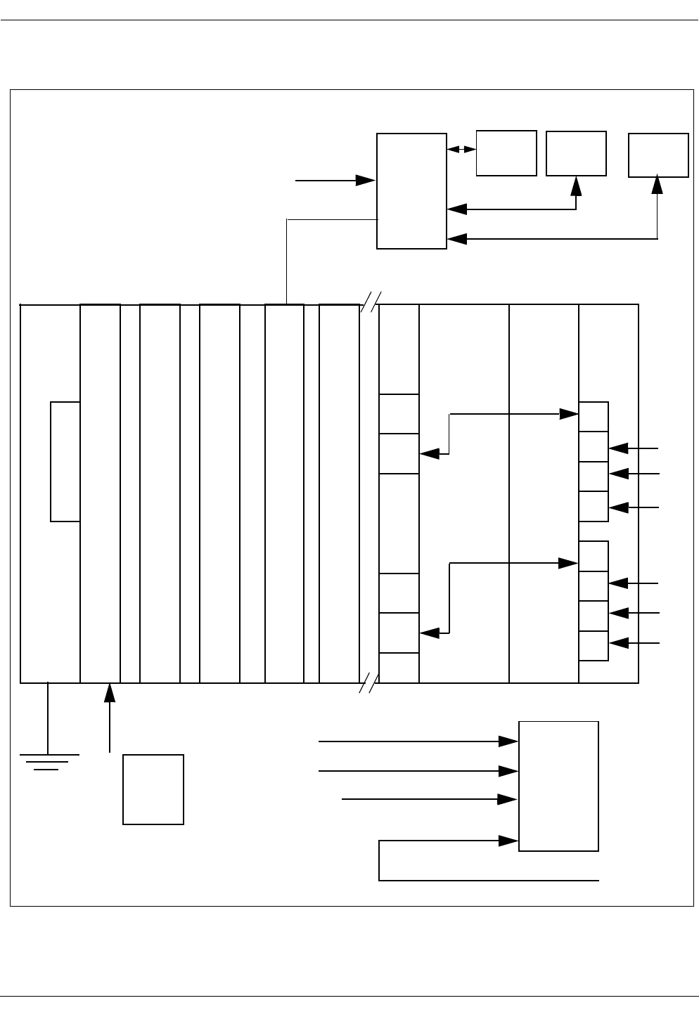
Figure 2 CRE Main Cabinet Example
CPM
S
Y
N
C
RLU RLU RLU SPU DTU SWB
123 4 5 6 9 1011
RH
P
u
n
c
h
RLU Cables -48 Vdc
Power
B
l
o
c
kCAT 5 Cables
Premise
RH
Scanner
E1/T1 links
E1 Link
E1 Link
Earth
Ground
Cable
Power
Cables
P
o
r
t
s
1
2
3
4
5
6
7
8
Mobility
Server
WOS SS7 Link
WWW Link
Ethernet Links

User Manual—Mobile Advantage Wireless Office (DWOS 1.0)
198 17-HRC104 201 PA9 17 (80)
2.4.2.2 CRE Component Descriptions
The component descriptions and slot assignments of the boards in the CRE
main and auxiliary cabinets are as follows:
•The CRE backplanes have 11 connecting slots that route signal and
power busses to the boards. A ribbon cable connects the backplanes
together in two-cabinet installations.
•The Synchronization (SYNC) board is inserted into slot one of the main
cabinet. The SYNC board provides system timing to all CRE boards
except the SWB. Only the CRE main cabinet requires the SYNC board.
•The CRE Power Module (CPM) boards, located in slot two in both the
main and auxiliary cabinets, provide the power to all of the boards in each
cabinet. The CPM and SYNC boards have the component side facing left
when viewed from the front; all other boards have the component side
facing right. The CPM boards convert the -48 Vdc local power input to
+5 Vdc and +3 Vdc outputs to the power bus on the backplanes. The CPM
boards also supply -48 Vdc to the SWB, SYNC board, and all Radio Link
Unit (RLU) boards, except the RLU board in slot three.
•Radio Link Unit (RLU) boards receive clock signals from the backplane
and provide clock signal synchronization and data transfer to the Radio
Heads (RH) and Scanners. RLUs perform pre-processing of Radio
Network Control (RNC) measurements and TDMA-136 formatting.
Each RLU can be connected to a maximum of eight RHs or Scanners. A CRE
can be configured with a maximum of four RLUs to support a total of 32 RHs
or Scanners. RLUs supply remote power through CAT 5 cables to RHs
mounted less than 800 meters (2640 feet) from the CRE. RLUs also provide
remote power to Scanners located less than 1200 meters (3960 feet) from the
CRE.
•The RLU board, located in slot three of the main cabinet, functions as a
central processor, providing Call Control, Radio Network Control, and
O&M configuration to the CRE.
Note: Do not attach RLU cables to the connectors of an RLU board
when it is inserted in slot three of the main cabinet.
•The Signal Processing Unit (SPU) board performs the Digital Control
Channel Handler (DCCH) functions and Digital Traffic Control (DTC)
handler functions. The DTC handler establishes and maintains traffic
channels. A single SPU can process seven simultaneous calls. Additional
SPUs can process eight simultaneous calls each. Using multiple SPU
boards provides a pool of time slot handlers that are dynamically
allocated to calls in progress. SPU boards also provide the following
features:
-
Channel coding and decoding
-
Speech coding and decoding
-
Echo canceling

User Manual—Mobile Advantage Wireless Office (DWOS 1.0)
18 (80) 198 17-HRC104 201 PA9
•The Digital Trunk Unit (DTU) board, in slot nine of the main cabinet,
interfaces with two E1 links to the SWB board and decodes the speech
and data busses. The two E1 links provide 60 full-duplex voice channels.
•The SWB, in slots 10 and 11 of the main cabinet, connects Mobile
Advantage to the local PBX and performs call switching. Up to six links
are configurable between the SWB and the PBX. The physical interfaces
between the SWB and the PBX are twisted pair, 120 ohm (E1) or 100
ohm (T1) balanced cables.
2.4.3 Radio Heads (RH)
Ericsson recommends vertical mounting of RHs on internal walls in the
Mobile Advantage coverage area. Each RH provides five transceivers for air
interface communications with mobile phones using the TDMA-136
protocol. In a typical office environment, an RH has a typical coverage radius
of 40 meters (132 feet).
RHs are connected with CAT 5 cables through punch blocks to RLU boards
in the CRE. RHs receive control, data, and power through the RLU boards if
located less than 800 meters (2640 feet) from the CRE. RHs with longer cable
runs (up to1600 meters or 5280 feet) from the CRE, must be provided with a
115 Vac to 24 Vdc power converter.
2.4.4 Scanners
Scanners connect to RLU boards in the CRE and provide neighboring cell
PLMN frequency usage information to Mobile Advantage. Information from
the Scanners is used by Mobile Advantage to minimize interference on
Mobile Advantage and PLMN frequencies.
Scanners are connected with CAT 5 cables through punch blocks to RLU
boards in the CRE. Scanners receive control, data, and power through the
RLU boards if located less than 1200 meters (3960 feet) from the CRE.
Scanners with longer cable runs (up to1600 meters or 5280 feet) from the
CRE must be provided with a 115 Vac to 24 Vdc power converter.
2.4.5 Mobile Advantage Mobile Phones
Mobile Advantage mobile phones are cellular or PCS phones that are
compatible with TDMA-136 standard protocol and capable of ACELP speech
encoding. Generic instructions for programming the mobile phones to
function within the Mobile Advantage environment is provided in this
section. More specific information about compatible products can be obtained
on-line on the Ericsson WEB page.
Writer’s Note:This document will contain generic specifications for the
TDMA-136 mobile phones as well as a generic description
of how to program a phone for use in DWOS. In the
HTML version, there should be a link to the Ericsson
WEB site that contains more specific information.

User Manual—Mobile Advantage Wireless Office (DWOS 1.0)
198 17-HRC104 201 PA9 19 (80)
3 Site Planning
Site planning evaluates the capacity needs of the Mobile Advantage system
and optimum placement of the components. The Mobile Advantage coverage
area is considered to be one cell.
In the planning phase the customer must complete a Site Planning Checklist
provided by Ericsson. Alternately, the customer can order a Site Survey to be
performed by Ericsson trained personnel to fulfill the following site planning
requirements:
•Determine the amount, location, and power requirements of the Mobility
Server, the CRE cabinets, Radio Heads, and Scanners.
•Define the external links and protocols required for Mobile Advantage to
communicate with the Private Telephone Network (PTN), the Internet,
and the Public Land Mobile Network (PLMN).
•Specify all cabling requirements within and external to the Mobile
Advantage system. List what components are supplied with the Mobile
Advantage system and what components are to be purchased locally.
•List any environmental requirements, distance limitations, and capacity
determinations.
3.1 Site Capacity and Reliability
The maximum physical coverage area and simultaneous call capacity
requirements determine unit configuration. A fully configured system can
process a maximum of 60 simultaneous calls.
Mobile Advantage can process 45 Erlang traffic at a Grade of Service (GOS)
of 0.5 percent. A GOS refers to the percentage of calls that could be blocked
during maximum traffic times. For example, at a GOS of 0.5 percent, Mobile
Advantage can process calls for up to 448 users if traffic for each user is
approximately 100 mErlang.
When estimating the maximum capacity in call processing of a Mobile
Advantage site, allowances should be made for redundant capacity. For
example, the call processing capabilities of SPU boards are added together in
the CRE to provide a pool of processing resources. When determining the
number of required SPU boards, allowing for extra capacity will, in the event
of an SPU board failure, maintain the GOS.
Estimated internal and external traffic requirements will determine the
required number of physical links from the CRE to PBXs or other units.
3.2 Mobility Server Planning
The Mobility Server component in Mobile Advantage is specified by Ericsson
to support all possible configurations of the system. Site planning for the
Mobility Server consists of estimating the power requirements and
connections to Mobile Advantage components and external links. All TCP/IP
connections information, including IP addresses of the connecting ports, must

User Manual—Mobile Advantage Wireless Office (DWOS 1.0)
20 (80) 198 17-HRC104 201 PA9
be entered in the Site Planning Checklist for use in the Mobile Advantage
installation and initialization phases.
The Mobility Server is powered by redundant -48 Vdc power supplies. The
type and location of all power requirements must be predetermined during the
site planning.
3.2.1 Mobility Server Connections
The following connection information is entered into the Site Planning
Checklist during the Mobile Advantage site planning phase:
•To enable remote WWW O&M access to Mobile Advantage, a TCP/IP
connection to the Internet on a local LAN, dedicated router, or
communications server must be supplied.
•To access the HLR in the SS7 network, a connection must be supplied
from the Mobility Server to a WOS SS7 Gateway Server. The protocol is
ANSI-41 Rev D; the bearer is TCP/IP on Ethernet.
•Two Ethernet connections are required from the Mobility Server to the
CRE main cabinet. Two reverse CAT 5 cables with RJ-45 connectors are
supplied with the system. The Ethernet connections are from the Mobility
Server to:
-
the RLU board inserted in slot three of the CRE main cabinet, and
-
the SWB inserted in slot 10 and extending over slot 11 of the main
cabinet. The SWB board requires two slots spaces.
3.3 Cellular Radio Exchange (CRE) Planning
The CRE for Mobile Advantage is configured in one or two cabinets. The
CRE auxiliary cabinet must be installed to the right of the CRE main cabinet.
The quantity of cabinets required must be determined in the site planning
phase.
Note: When installing single-cabinet systems allocate space to the right of
the main cabinet for an expansion cabinet.
In Mobile Advantage a main and one auxiliary cabinet can support the
maximum quantity of system boards (SPU and RLU). Site planning
determines the optimum quantity of each board. Adding extra SPUs, RLUs,
or RHs to Mobile Advantage can provide redundancy in coverage and
processing capabilities in event of failure. The maximum number of Mobile
Advantage CRE boards are as follows:
•Eight SPU boards—The first SPU board can process seven simultaneous
calls. Each additional board can process eight calls except the eighth
which can process five calls (7+8+8+8+8+8+8+5 = 60). Eight SPU
boards provide a processing pool capable of handling a total of 60
simultaneous calls.
•Four RLU boards—Each RLU board can support a maximum of eight
RHs. Each RH can process a maximum of 14 simultaneous calls.

User Manual—Mobile Advantage Wireless Office (DWOS 1.0)
198 17-HRC104 201 PA9 21 (80)
Note: The amount of RLU boards configured will determine the amount
of punch blocks required. Each RLU board is cabled to one punch
block. Placement of the punch blocks is also determined during
site planning.
3.3.1 CRE connections
The amount, type, and location of the CRE connections are determined in the
site planning phase. The following information is considered when
completing the Site Planning Checklist:
•Mobile Advantage supports a maximum of six external T1 or E1 trunk
links between the SWB and PBXs.
Note: E1 or T1 cables, 15 meters (50 feet) in length, are supplied with
the system for connections to equipment located in the same room
as the CRE. The connectors of the cables supplied by Ericsson
meet specific shielding requirements to comply with radiated
emissions regulations. If the location of PBXs require extensions,
they must be connected to the cables supplied by Ericsson, to
meet requirements.
•Two standard RLU telephony cables are supplied for use between each
configured RLU board and the punch blocks. Each punch block is
connected to a maximum of eight RHs or Scanners with standard CAT 5
cables.
Note: When connecting the cables to RLU boards consider whether
redundant RH coverage is necessary. When locating an RH near
another RH, to provide for redundant coverage in an area, do not
connect to the same RLU board. The failure of a single RLU
would not cause loss of coverage if redundant RHs are connected
to different boards.
•-48 Vdc power cables are supplied for each cabinet.
•A PE ground cable is supplied for each cabinet.
•Two Ethernet connections are required from the Mobility Server to the
CRE main cabinet. Reverse CAT 5 cables with RJ-45 connectors are
supplied with the system. The CAT 5 cables are connected from the
Mobility Server to the following:
-
The RLU board located in slot three of the CRE main cabinet.
-
The SWB in the CRE main cabinet. The SWB is inserted in slot 10
and extends over slot 11 of the main cabinet.
3.4 RH Planning
The number of required Radio Heads is determined by analyzing physical site
requirements and user location estimates. Estimating the location and number
of RHs is determined using site floor plans. A method of determining the level
of external radio interference is used. The level of radio interference measured

User Manual—Mobile Advantage Wireless Office (DWOS 1.0)
22 (80) 198 17-HRC104 201 PA9
during site planning will effect the planned number of RHs, the RH
transmitted power, and maximum mobile phone power. Higher external radio
interference levels require more RHs.
The number of RHs must be sufficient to perform the following:
•Provide the necessary carrier to noise levels ratio
•Allow low enough transmitted power level to minimize interference to
external systems
•Provide call completion without blocking for the estimated number of
users in all areas. An RH can be mounted near another RH in areas where
large concentrations of users are predicted or redundant coverage is
needed.
3.4.1 Estimating Radio Coverage
The customer’s desired radio coverage area must be understood before a
system quotation can be provided. Radio coverage is provided by the strategic
placement of Radio Heads and Scanners. The Mobile Advantage system can
support up to 32 Radio Devices: RHs and Scanners. Coverage can be
estimated using the following three methods, shown in order of increasing
reliability.
1. Square footage estimate
The configuration provides an estimate of how many square feet a given
number of Radio Heads will cover. Although it is possible to provide
budgetary quotations from square footage alone, this is not recommended.
2. Floor plans
If provided with floor plans, Sales Engineering can formulate a more accurate
estimate of how many Radio Heads and Scanners are required to cover a given
facility. Quotations based solely upon floor plans must include a provision
stating to the customer that the actual number of Radio heads required may
vary (higher or lower). Ericsson will not guarantee coverage based solely
upon floor plans. If a firm quotation is required, a Site Survey must be ordered
from the Ericsson Service Group.
3. Site Survey
A Site Survey is the most accurate way to assess needed radio coverage.
Using the TEMS™ radio Site Survey tool, an Ericsson-trained technician will
walk through a customer’s facility taking measurements to ensure the optimal
placement of Radio Heads. A Site Survey will usually be employed in the
later stages of the sales process but prior to making any contractual
agreements.
3.4.2 RH Connections
RHs are connected by solid wire CAT 5 cables to designated pins on the
punch blocks. For more information about RH cabling see “Appendix A—
Cabling and Connectors”, on page 58.

User Manual—Mobile Advantage Wireless Office (DWOS 1.0)
198 17-HRC104 201 PA9 23 (80)
Note: Local RHs located less than 800 meters (2640 feet) from the CRE
receive power from the RLU boards through the CAT 5 cables. RHs
located 800 to 1600 meters (2640 to 5280 feet) from the CRE must
have a 115 Vac outlet located nearby.
3.5 Scanner Planning
The number and location of required Scanners are determined by analyzing
physical site requirements and macro cell interference studies. A minimum of
two Scanners are required for each Mobile Advantage system.
3.5.1 Scanner Connections
Scanners are connected by solid wire CAT 5 cables to designated pins on the
punch blocks. For more information about Scanner cabling see “Appendix
A—Cabling and Connectors”, on page 58.
Note: Scanners located less than 1200 meters (3960 feet) from the CRE
receive power from the RLU boards through the CAT 5 cables.
Scanners located 1200 to 1600 meters (3960 to 5280 feet) from the
CRE are powered by a 24 Vdc converter and must have a 115 Vac
outlet located nearby.

User Manual—Mobile Advantage Wireless Office (DWOS 1.0)
24 (80) 198 17-HRC104 201 PA9
4 Site Preparation
This section provides site preparation requirements for Mobile Advantage
components.
Note: After following the procedures in Site Preparation go to Chapter 5,
“Installation,” on page 27 followed by Chapter 6, “Integration and
Test,” on page 36, to complete the Mobile Advantage installation.
4.1 Environmental Requirements
CRE cabinets are to be mounted on an indoor wall on a panel that is secured
to wall studs. The premises must comply with the following prerequisites:
•The ambient air must be free of dust, smoke, gases and acid fumes.
•The temperature range where the CRE and Mobility Server are located
must be between +5°C and +40°C and relative humidity may vary
between 15% and 80%.
•The temperature range where the RHs and Scanners are located must be
between 0°C and +55°C with a relative humidity of up to 100%
non-condensing.
Note: Sensors within the RHs and Scanners monitor temperature levels
and will shut down at elevated levels.
•The relationship between temperature and air humidity in the Mobile
Advantage area must not cause condensation.
•The CRE should not be exposed to direct sunlight
•Cables should run into the CRE from below the cabinet to ensure
sufficient air flow and space.
If batteries are in the room where Mobile Advantage components are located,
they must be of such type that does not produce gases or acid fumes.
Note: Auxiliary cabinets must be installed to the right of the main cabinet
(cabinet one). When installing a single-cabinet or a two-cabinet
system, leave room to the right for adding expansion cabinets.
4.2 Power Requirements
The following power sources are required.
•The Mobility Server is powered with a -48 Vdc power source. The -48
Vdc power is supplied from the PBX battery regulated supply or from a
separate Uninterruptible Power Source (UPS).
•The CRE must be supplied with -48Vdc from the PBX battery regulated
supply or from a separate UPS.
•Each RH or Scanner requires a power source. RHs located less than 800
meters (2640 feet) from the CRE, receive power remotely from the RLU
boards through the CAT 5 cables. Scanners located less than 1200 meters

User Manual—Mobile Advantage Wireless Office (DWOS 1.0)
198 17-HRC104 201 PA9 25 (80)
(4356 feet) from the CRE, also receive power from the RLU boards. If
RHs or Scanners cable distances are longer (up to1600 meters or 5280
feet) they receive power from a 24 Vdc converter. A 115 Vac outlet must
be located nearby to supply power to the converters, if used to power RHs
or Scanners.
4.3 RH and Scanner Cable Installation
Before beginning the procedures in this section, print a copy of Chapter 11,
“Appendix A—Cabling and Connectors,” on page 58, to use with all
installation procedures.
Installing the cables and punch block wiring for the RHs and Scanners can be
done before receiving the main Mobile Advantage units. The physical
requirements of the Mobile Advantage area and the planned location of the
RHs or Scanners from the site planning phase determine the best cable
routing.
Note: Cables that are routed through ceilings or plenums must be rated for
fire safety. The applicable cable plenum specifications are defined in
NEC CMP and CSA PCC FT4/FT6.
4.3.1 Installing Cables From The CRE to RHs or Scanners
Perform the following steps to correctly install the RLU cables from the RLU
boards to the punch blocks and CAT5 cables from the punch blocks:
1. Determine the number and location of the RHs, Scanners, punch blocks,
and CRE cabinets from the site planning documents.
2. Install the required amount of punch blocks in the correct location. Punch
blocks are usually installed on wall-mounted panels or racks.
3. Attach labels to the punch blocks to identify which functional RLU
board (for example, RLU1 to RLU4) will be connected to the punch
block.
Note: When cabling from the RLU boards to punch blocks, do not
connect to the RLU board in slot three of the main cabinet. The
RLU board in slot three functions as a central processor and is not
connected to RHs or Scanners.
4. If the RLU to punch block cables supplied with the system are available,
label and connect them to the designated punch blocks.
Note: The cable from the top telephony connector (DB-37) on each
RLU board routes to the telephony connector on the top left side
of the designated punch block. The cable from the bottom
telephony connector on each RLU board routes to the connector
on the bottom right side of the designated punch block.
5. Route the customer supplied CAT 5 cables from the positions of up to
eight RHs or Scanners to the designated punch block.

User Manual—Mobile Advantage Wireless Office (DWOS 1.0)
26 (80) 198 17-HRC104 201 PA9
Note: Redundant RHs covering the same area should not be connected
to the same RLU board. Connecting redundant RHs to separate
punch blocks and RLU boards allows for continuing coverage of
an area in case of RLU board failure.
6. Attach identification labels to both ends of the designated CAT 5 cables
indicating the connections (for example, RHx through RHy).
7. If the RHs or Scanners are installed, connect the RJ-45 connector ends
of the CAT 5 cables.
8. At the punch blocks cut and prepare the CAT 5 cables installed in Step 7.
9. Using Table 10, “RLU CAT 5 Cables From Punch Block to RHs or
Scanners Signals and Pins”, on page 63, connect the cut ends of the CAT
5 cables to the correct pins on the designated punch blocks.
10. End of procedure. Upon receipt of the remaining Mobile Advantage
system units continue with Chapter 5, “Installation,” on page 27.

User Manual—Mobile Advantage Wireless Office (DWOS 1.0)
198 17-HRC104 201 PA9 27 (80)
5 Installation
5.1 Dangers, Warnings, and Cautions
All cabinets must be grounded to Protective Earth (PE).
The CRE cabinets must be connected to PE according to local regulation and
in compliance with IEC publication 364 (or HD 384) “Electrical installations
of buildings”. See the diagram in Figure 9, Recommended CRE Power and
Grounding, on page 59, for more information.
Work affecting PE or power sources must be inspected or carried out under
supervision of an authorized licensed electrician. The following must be
considered:
•The risk that a short circuit of a battery negative side to the ground of the
building will destroy (burn off) the PE ground.
•The continuity of PE ground cannot be affected by work carried out on
parts that do not concern the PE ground.
•The required PE marking symbols must be present on ground cable
connections.
5.1.1 Protection against Electrostatic Discharge (ESD)
Mobile Advantage uses components that are sensitive to ESD. To avoid
damage caused by ESD, service personnel should be grounded when handling
equipment and boards.
To make sure that equipment and parts are well protected during shipment,
special packaging materials are utilized. System boards will be shipped in
anti-static bags.
5.1.1.1 ESD handling
Figure 3 Handling ESD boards

User Manual—Mobile Advantage Wireless Office (DWOS 1.0)
28 (80) 198 17-HRC104 201 PA9
Observe the following rules when handling system boards and parts.
•Service personnel must ground themselves by using an ESD wrist strap
when exchanging system boards. The CRE cabinets are equipped with
ground connections, located on the front and back of the cabinet, for ESD
straps.
•Keep system boards and other parts in ESD protective packaging until
use.
•Do not stack a system board on another system board.
•When returning system boards or parts, use the recommended protective
packaging.
•Never underestimate the damage potential of ESD. Be especially careful
when temperatures are near freezing, humidity is low, or the temperature
exceeds the recommended environmental limits in this manual.
5.2 Installing RHs or Scanners
Execute the following steps to install RHs and Scanners.
1. Place RHs or Scanners in the locations determined in the site planning
phase. Use the mounting template provided with the system.
2. Connect power converters to the RHs or Scanners that are located to far
from the CRE to receive remote power. RHs located less than 800 meters
(2640 feet) from the CRE, receive power remotely from the RLU boards
through the CAT 5 cables. Scanners located less than 1200 meters (4356
feet) from the CRE, also receive power from the RLU boards. If RHs or
Scanners cable distances are longer (up to1600 meters or 5280 feet) they
receive power from a 24 Vdc converter. A 115 Vac outlet must be
located nearby to supply power to the converters, if used to power RHs
or Scanners.
3. Connect the CAT 5 cables from the punch blocks to the RHs or Scanners.
4. Verify labeling on all cables at the RJ-45 connector end and at the pinch
blocks.
Note: The CAT 5 cables were installed in Chapter 4.3.1, “Installing
Cables From The CRE to RHs or Scanners,” on page 25.
5. End of procedure. Do not apply power to the RHs or Scanners at this
time. Go to Chapter 5.3, “Installing the Mobile Advantage Mobility
Server,” on page 28.
5.3 Installing the Mobile Advantage Mobility Server
The Mobility Server is configured at the factory with all required Ericsson
Mobile Advantage software and the Microsoft Windows NT™ operating
system. All Licensing software is installed. Remote Access Software (RAS)
is installed and configured to the serial interface port. A service laptop is
required to interface with the Mobility Server.

User Manual—Mobile Advantage Wireless Office (DWOS 1.0)
198 17-HRC104 201 PA9 29 (80)
1. Connect the Mobility Server to the required power source as shown in the
Site Plan. Do not turn ON the Mobility Server at this time.
2. Connect the Mobility Server Network Interface Card (NIC) first Ethernet
port to the LAN hub or Server that will provide access to the Internet
(WWW).
3. Connect the Mobility Server NIC second Ethernet port to the LAN hub
or server that will provide access to the WOS SS7 Gateway.
4. Connect the service laptop computer to the serial port.
5. Turn ON the laptop computer.
6. Turn ON the Mobility Server.
7. Observe the successful initialization of the Mobile Advantage software
and NT 4.0 operating system with Service Pack 3. An image of the
Mobility Sever is mapped to the laptop through the RAS link.
8. Execute the installation wizard (ELWIZ) from the laptop computer. The
Mobility Server will start the installation script.
9. Configure the Mobility Server browser and TCP/IP interface to access
the Internet and the WOS SS7 Gateway.
Note: The configuration information is obtained from the Site Planning
Checklist.
10. Restart the Mobility Server to implement the configuration changes.
11. Obtain the e-mail address assigned to the Mobility Server Administrator
from the Site Planning Checklist.
Note: To obtain the Mobile Advantage license the target ID number and
the e-mail address of the Mobility Server System Administrator
must be sent to Ericsson.
12. Send the license information (target ID number + Administrator’s e-mail
address) to Ericsson. The license number will be returned for use in the
Mobile Advantage initialization procedures.
13. Turn OFF power to the Mobility Server.
14. End of procedure. Go to Chapter 5.4, “Installing a Cellular Radio
Exchange (CRE),” on page 29.
5.4 Installing a Cellular Radio Exchange (CRE)
Installing the CRE consists of mounting the cabinet or cabinets in the
locations predetermined during the site planning, and attaching all power,
ground, and communication cables. This section describes separate
procedures for the following CRE installations:
•Installing a single-cabinet (Main) Wall-Mounted CRE go to
Section 5.4.1 on page 30.

User Manual—Mobile Advantage Wireless Office (DWOS 1.0)
30 (80) 198 17-HRC104 201 PA9
•Installing a Two-Cabinet (Main and Auxiliary) Wall-Mounted CRE go to
Section 5.4.2 on page 32.
When performing the following procedures, use a printed copy of Chapter 11,
“Appendix A—Cabling and Connectors,” on page 58 of this manual.
Note: CRE auxiliary cabinets provide only expansion space for additional
RLU and Signal Processing Unit (SPU) boards. An auxiliary cabinet
requires only cabling for power, PE grounding, and any configured
RLU boards.
5.4.1 Installing a single-cabinet (main) Wall-Mounted CRE
Perform the following procedure to install a single CRE main cabinet in the
position determined during the site planning . When positioning the cabinet
vertically take into consideration that the normal working height above the
floor is about 1.30 meters (4.5 feet) from the lower edge of the cabinet.
1. Unpack the CRE main cabinet and observe any indications of damage in
shipping. If damage is observed contact Ericsson or the supplier.
2. Inspect the shipping container contents and compare the shipping
material lists. Separate cables by part number.
3. Mount a panel secured to the building wall studs to attach the CRE
cabinets. To locate wall studs use a commercial stud finder.
Note: The combined weight of the CRE cabinets and boards, defined in
Table 15, “CRE Cabinet Specifications”, on page 77, require
mounting on panels or racks that are secured to wall studs.
4. Obtain the CRE Cabinet mounting template that was shipped with the
system.
5. On the mounting panel, tape the template in place and, using a punch,
mark the location of the four screw holes that will be used to mount the
main cabinet.
6. Remove the template.
7. Insert two mounting screws, supplied with the cabinet, in the top two
marked positions. Leave a space of one-quarter inch between the wall
and screw heads to allow the slots in the cabinet case to slip over the
screws when mounting.
8. Mount the main cabinet in position by setting the large slotted holes in
the back case over the top mounting screws and slowly lowering until the
screws slip into the slots.
9. Remove the front cabinet cover.
10. Remove the bottom cabinet cover.
11. Insert the two lower screws and tighten all four cabinet mounting screws.
12. Place the edge of the template against the right side of the main cabinet
and tape in place. For future additions to the system, mark the holes to
mount a expansion cabinet.

User Manual—Mobile Advantage Wireless Office (DWOS 1.0)
198 17-HRC104 201 PA9 31 (80)
13. Remove the template.
14. Connect the main cabinet case to Protective Earth (PE) as shown in
Figure 9, Recommended CRE Power and Grounding, on page 59, using
the ground cable provided with the system.
15. Put on an ESD wrist strap and attach it to the ground wire braid on the
front of the main cabinet.
16. Connect the RJ-45 connector of a reverse CAT 5 cable, supplied with the
system, to the Ethernet connector on the RLU board inserted in slot three
of the main cabinet.
Note: The RLU board in slot three of the main cabinet functions as a
central processor. The Ethernet connection is the Mobility Server
interface link to the CRE.
17. Connect the RJ-45 connector on the other end of the cable installed in
Step 16. to the Mobility Server NIC Ethernet third port.
18. Connect the RJ-45 connector of a reverse CAT 5 cable, supplied with the
system, to the Ethernet connector on the SWB in slots 10 and 11 of the
CRE.
19. Connect the other end of the CAT 5 cable installed in Step 18. to the
Mobility Server NIC fourth Ethernet port.
20. Connect an RLU cable from the top telephony connector (DB-37) on the
front panel of the first available RLU board (not in slot three) of the main
cabinet.
21. The other end of the cable is connected to the top left side connector of
the punch block assigned to the RLU board. See Step 3. of the procedure
in Chapter 4.3.1, “Installing Cables From The CRE to RHs or Scanners,”
on page 25, for more information.
22. Connect an RLU cable from the bottom telephony connector (DB-37) of
the RLU board referenced in Step 20.
23. Connect the other end of the RLU cable to the connector on the bottom
right side of the designated punch block.
24. Repeat Step 20. through Step 23. for the remaining RLU boards in the
CRE main cabinet.
25. Check the internal connections between the DTU board in slot nine and
the SWB. The SWB is inserted in slot 10; the PCM ports extend over slot
11 of the main cabinet. The two short E1 links are installed at the factory.
The E1 cable from the top PCM connector on the DTU board connects
to PCM port one on the SWB. The cable from the bottom PCM
connector on the DTU board connects to PCM port five on the SWB.
Note: The PCM ports on the SWB are numbered one through eight
starting from the top.
26. Connect the T1 or E1 cables that are going to the PBX, to external T1/E1
PCM ports on the SWB. When using T1 PBX links connect to PCM
ports two and six first. For information about T1 or E1 connections see

User Manual—Mobile Advantage Wireless Office (DWOS 1.0)
32 (80) 198 17-HRC104 201 PA9
Table 12, “SWB T1 Signal Names and Pin Numbers”or Table 13, “SWB
E1 Signal Names and Pin Numbers”.
27. Connect the -48 Vdc power source cables to the power connector on the
front of the CPM board in slot two of the main cabinet. Use Table 7,
“Power and PE Ground Cables”for connection information. Do not turn
ON power to the CRE at this time.
28. Remove the ESD wrist strap.
29. Replace the cabinet bottom and front covers.
30. End of procedure. Go to Chapter 6, “Integration and Test,” on page 36,
to complete initialization of the Mobile Advantage system.
5.4.2 Installing a two-cabinet (Main and Auxiliary) Wall-Mounted CRE
Perform the following procedure to install the two CRE cabinets in the
positions determined during the site planning. When positioning the cabinets
take into consideration that the normal working height above the floor is about
1.30 meters (4.5 feet) from the lower edge of the cabinet.
1. Unpack the cabinets and observe any indications of damage in shipping.
If damage is observed contact Ericsson or the supplier.
2. Inspect the shipping containers contents and compare the shipping
material lists. Separate cables by part number.
3. Mount a panel secured to the building wall studs to attach the CRE
cabinets. To locate wall studs use a commercial stud finder
Note: The combined weight of the CRE cabinets and boards, defined in
Table 15, “CRE Cabinet Specifications”, on page 77, require
mounting on panels or racks that are secured to wall studs.
4. Obtain the CRE Cabinet mounting template that was shipped with the
system.
5. On the mounting panel, tape the template in place and, using a punch,
mark the location of the four screw holes that will be used to mount the
main cabinet.
6. Remove the template.
7. Insert two mounting screws, supplied with the cabinet, in the top two
marked positions. Leave a space of one-quarter inch between the wall
and screw heads to allow the slots in the cabinet case to slip over the
screws when mounting.
8. Mount the main cabinet in position by setting the large slotted holes in
the back case over the top mounting screws and slowly lowering until the
screws slip into the slots.
9. Remove the main cabinet front cover.
10. Remove the main cabinet bottom cover.

User Manual—Mobile Advantage Wireless Office (DWOS 1.0)
198 17-HRC104 201 PA9 33 (80)
11. Insert the two bottom screws in the main cabinet back case and tighten
all four cabinet mounting screws.
12. Place the edge of the template against the right side of the main cabinet
and tape in place. Mark the holes to mount the auxiliary cabinet.
13. Insert two mounting screws, supplied with the cabinet, in the top two
marked positions. Leave a space of one-quarter inch between the wall
and screw heads to allow the slots in the cabinet case to slip over the
screws when mounting.
14. Mount the auxiliary cabinet in position by setting the large slotted holes
in the back case over the top mounting screws and slowly lowering until
the screws slip into the slots.
15. Remove the auxiliary cabinet front cover.
16. Remove the auxiliary cabinet bottom cover.
17. Insert the two bottom screws in the auxiliary cabinet back case and
tighten all four cabinet mounting screws.
18. Connect the cabinet cases to Protective Earth (PE) as shown in Figure 9,
Recommended CRE Power and Grounding, on page 59, using the
ground cable provided with the system.
19. Put on an ESD wrist strap and attach it to the ground wire braid on the
front of the CRE main cabinet.
20. Remove the boards in slots ten and eleven of the main cabinet. Place
boards individually into ESD protective bags. Do not stack boards.
21. Remove the board in slot two of the auxiliary cabinet. Place the board
into the ESD protective bag. Do not stack boards.
22. Connect the backplane interconnecting ribbon cable, supplied with the
system, to the designated backplane connectors in the main cabinet.
Figure 4 illustrates the backplane cable connections.
User Manual—Mobile Advantage Wireless Office (DWOS 1.0)
34 (80) 198 17-HRC104 201 PA9
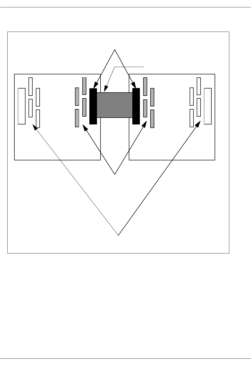
Figure 4 CRE backplane interconnecting cables
23. Route the flat ribbon cable through the spring fingers surrounding the
feed-through holes.
24. Connect the flat ribbon cable to the designated backplane connector in
the auxiliary cabinet.
25. Replace the boards removed in Step 20. and Step 21.
26. Connect the RJ-45 connector of a reverse CAT 5 cable, supplied with the
system, to the Ethernet connector on the RLU board inserted in slot three
of the main CRE cabinet
Note: The RLU board in slot three of the main cabinet functions as a
central processor. The connection is required for the Mobility
Server interface link to the CRE.
CRE
Main
Cabinet
CRE
Auxiliary
Cabinet
These resistor packs
Leave these resistor packs in
Interconnecting Cable,
Backplane Connectors
are removed
Red line (indicating pin one)
toward top of cabinet

User Manual—Mobile Advantage Wireless Office (DWOS 1.0)
198 17-HRC104 201 PA9 35 (80)
27. Connect the RJ-45 connector on the other end of the cable installed in
Step 26. to the Mobility Server NIC Ethernet third port.
28. Connect the RJ-45 connector of a reverse CAT 5 cable, supplied with the
system, to the Ethernet connector on the SWB board inserted in slots 10
and 11 of the CRE main cabinet.
29. Connect the other end of the CAT 5 cable installed in Step 28. to the
Mobility Server NIC fourth Ethernet port.
30. Connect an RLU cable from the top telephony connector (DB-37) on the
front panel of the first available RLU board (not in slot three) of the main
cabinet.
31. The other end of the cable is connected to the top left side connector of
the punch block assigned to this RLU board. See Step 3. the procedure
in Chapter 4.3.1, “Installing Cables From The CRE to RHs or Scanners,”
on page 25
32. Connect an RLU cable from the bottom telephony connector on the front
panel of the first available RLU board (not in slot three) of the CRE
cabinet.
33. Connect the other end of the RLU cable to the connector on the bottom
right side of the designated punch block.
34. Repeat Step 30. through Step 33. for the remaining RLU boards in both
main and auxiliary cabinets.
35. Check the internal connections between the DTU board in slot nine and
the SWB in the main cabinet. The SWB is inserted in slot 10; the PCM
ports extend over slot 11 of the main cabinet. The two short E1 links are
installed at the factory. The E1 cable from the top PCM connector on the
DTU board connects to PCM port one on the SWB. The cable from the
bottom PCM connector on the DTU board connects to PCM port five on
the SWB.
Note: The PCM ports on the SWB are numbered one through eight
starting from the top.
36. Connect the T1 or E1 cables that are going to the PBX, to external T1/E1
PCM ports on the SWB. When using T1 PBX links connect to PCM
ports two and six first. For information about T1 or E1 connections see
Table 12, “SWB T1 Signal Names and Pin Numbers”or Table 13, “SWB
E1 Signal Names and Pin Numbers”.
37. Connect the -48 Vdc power source cables to the power connector on the
front of the CPM board in slot two of both cabinets. Use Table 7, “Power
and PE Ground Cables”for connection information. Do not turn ON
power to the CRE at this time.
38. Remove the ESD wrist strap.
39. Replace the cabinet bottom and front covers.
40. End of procedure. Go to Chapter 6, “Integration and Test,” on page 36,
to complete initialization of the Mobile Advantage system.

User Manual—Mobile Advantage Wireless Office (DWOS 1.0)
36 (80) 198 17-HRC104 201 PA9
6 Integration and Test
Integration of the Mobile Advantage consists of configuring the system and
allocating the frequencies to be used. After integration is complete the Mobile
Advantage is initialized and can provide call services.
6.1 Integration
The integration phase follows the physical installation of Mobile Advantage
and ends when all necessary configuration data is entered. The CRE IP
address must be set before O&M tasks can be executed. Configuration data
that is not pre-defined is manually entered by the O&M user.
Configuration data entered by the O&M User is divided into the following
categories:
•Security Data—User Identification, Password, and Access Level
•Radio Network Data—Radio network frequencies and control
parameters
Note: Some parameters cannot be changed by the user, but are only
accessible in a configuration file which is managed by the system.
•Call Control Data—PBX Prefix and External Line Prefix
•Network Data—Trunk Line, Routes, and Interface Protocol Timers
•Subscriber Data—Subscriber name, Mobile Identification Number
(MIN), DWOS User Number, and Service Profile.
Note: For more information about configuring Mobile Advantage see
Chapter 8, “Operations, Administration and Maintenance
(O&M),” on page 42.
6.1.1 Initial frequency selection
The initial frequencies allocated to Mobile Advantage are determined by the
cellular operator. For site planning Ericsson provides a Site Survey service to
identify the best initial frequencies. During normal operation automatic
frequency allocation software determines the optimum frequency usage with
Scanners.
6.1.2 Mobile Advantage Initialization
The Mobile Advantage system is initialized by executing the following steps:
1. Turn ON the Mobility Server.
2. Obtain the CRE IP addresses and Bootfile name from the Site Planning
Checklist.

User Manual—Mobile Advantage Wireless Office (DWOS 1.0)
198 17-HRC104 201 PA9 37 (80)
Note: Configure the fixed SWB IP interface address (IP=172.16.2.50
Subnet Mask=255.255.0.0). The IP address of the RLU board in
slot three of the main cabinet is automatically configured when
the CRE is turned on if the Mobility Server NIC port is connected.
3. Turn ON power to the CRE. The Mobility Server indicates the CRE
status is UP and transfers the Bootfile information.
Note: For information about using other O&M functions after Mobile
Advantage is started see Chapter 8, “Operations, Administration
and Maintenance (O&M),” on page 42.
4. If there are RHs or Scanners located too far from the CRE to use its
power, then the 115 Vac which operates the power converters must be
be on for those units.
6.1.3 The ANSI-41 Link to the HLR
To access the HLR, Mobile Advantage connects through a WOS SS7
Gateway to the SS7 network. The ANSI-41 link provides administrative and
messaging between the Mobility Server and the WOS SS7 Gateway.
Administrative messages include heartbeat and initial configuration
messages. Heartbeat messages indicate the state of connections between the
Mobility Server and the ANSI-41 system. After configuration is complete the
Mobility Server can generate and respond to heartbeat messages.
The Mobility Server configuration message is received from the WOS SS7
Gateway system after initial establishment of the TCP/IP connection. The
Mobility Server is a client node to the WOS SS7 Gateway system and has to
send the initial connect() message to establish connection.
6.1.3.1 Setting the ANSI-41 TCP/IP Interface
Obtain the WOS SS7 Gateway IP addresses from the Site Planning Checklist.
At the selection of ANSI-41 in the “Hardware Resources” service area of the
Management System interface, enter the following data:
•The identity or name of the link
•The primary and secondary IP addresses and port numbers of the WOS
SS7 Gateway.
•The number of heartbeat failures before the interface between the
Mobility Server and the WOS SS7 Gateway is closed.
•The heartbeat time out interval in seconds.
•The link protocol (ANSI-41)
6.2 Post-Installation test
Writer’s Note:This section is to be expanded by TAC.

User Manual—Mobile Advantage Wireless Office (DWOS 1.0)
38 (80) 198 17-HRC104 201 PA9
Post-installation testing of a newly-installed Mobile Advantage system is
completed when Mobile Advantage subscribers can originate and receive
calls.

User Manual—Mobile Advantage Wireless Office (DWOS 1.0)
198 17-HRC104 201 PA9 39 (80)
7 Numbering Plans
Mobile Advantage provides one-number access to all users whether they are
in the system area or roaming in the PLMN. The 10-digit Direct In Dialing
(DID) number can access a Mobile Advantage user whether in the system area
or roaming in the PLMN. While in the system area, calling users can connect
to other users with a four or five-digit DWOS User Number (DUN), a subset
of the DID number. When Mobile Advantage mobile phone users in the
system area call external numbers the Calling Line Identification Presentation
(CLIP) to the called party is the DID number, unless an alternative number is
defined.
Administration and billing for Mobile Advantage users is simplified by the
one-number access capabilities. The Mobile Advantage and associated
PLMN determine system costs; the user is not billed for calls originated from
or destined to Mobile Advantage numbers. Although a Mobile Directory
Number (MDN) is assigned by the PLMN to all Mobile Advantage phones, it
is not recommended for typical usage. Calls originated or destined for MDN
numbers are billed directly to the user.
The Mobile Advantage numbering plan uses the following:
•PBX Extensions—The PBX extension number defines a physical
extension of a Mobile Advantage mobile phone. A PBX Extension
number can only be used by subscribers connected to the PBX or Mobile
Advantage users while in the system coverage area.
•DWOS User Numbers (DUN)—The DWOS User Number defines only
Mobile Advantage mobile phones. A DUN is used by subscribers
connected to the PBX or within the Mobile Advantage coverage area to
call other Mobile Advantage users.
•PBX Prefix—The PBX Prefix is the office code of the PBX in the PSTN.
The PBX prefix is added to the DUN to make a seven-digit directory
number.
•Numbering Plan Area Code (NPA)—The NPA identifies the calling code
of an area of the country. To make a national call, the NPA Code is added
to the seven-digit directory number.
•Direct In Dialing (DID)—The DID number is composed of the
NPA+PBX Prefix+DUN numbers (for example 919 555 1212). The DID
is presented as the CLIP when a Mobile Advantage user calls out of the
system area.
•Country Code (CC)—The CC identifies the calling code of a country. To
make an international call, the CC is added to the ten digit DID.
•External Line Prefix—Some PBX systems require dialing a number to
access the external networks. For example, dialing a 9 to get an outside
line.

User Manual—Mobile Advantage Wireless Office (DWOS 1.0)
40 (80) 198 17-HRC104 201 PA9
7.1 Examples of number usage
In the following examples the features; Follow Me In/Out and Calling Line
Identification Presentation (CLIP), of the calling and called phones are active.
The following examples describe Mobile Advantage number usage:
•A Mobile Advantage user in the system area calls another Mobile
Advantage user’s four or five-digit DWOS User Number (DUN). Mobile
Advantage then does one of the following:
-
If the called user is also in the system area, Mobile Advantage locates
the called mobile phone, completes the call connection, and presents
a CLIP consisting of the caller’s DUN to the called party.
-
If the called user is not in the system area, Mobile Advantage
interrogates the PLMN for the roaming routing number and
Temporary Local Directory Number (TLDN) to the called mobile
phone. The TLDN is temporarily allocated by a Mobile Services
Switching Center (MSC) for call setup and is used to route the call
through the PSTN or PLMN networks. Mobile Advantage locates
the called mobile phone, completes the call, and presents a CLIP
consisting of the caller’s Direct In Dialing (DID) number to the
called party.
•A Mobile Advantage user not in the system area calls another Mobile
Advantage user’s DID number. The call is routed through the PLMN and
PSTN to Mobile Advantage. Mobile Advantage then does one of the
following:
-
If the called user is in the system area, Mobile Advantage locates the
called mobile phone, completes the call connection, and presents a
CLIP consisting of the caller’s DUN to the called party.
-
If the called user is roaming in the PLMN, Mobile Advantage
interrogates the PLMN for the roaming routing number and TLDN
to the called mobile phone. Mobile Advantage locates the called
mobile phone, completes the call, and presents a CLIP consisting of
the caller’s DID to the called party.
•When a non-Mobile Advantage phone calls a Mobile Advantage user’s
DID number, the system does one of the following:
-
If the called user is in the system area, Mobile Advantage locates the
mobile phone, completes the call connection, and presents a CLIP
consisting of the caller’s DID number to the called party.
-
If the called user is roaming in the PLMN, Mobile Advantage
interrogates the PLMN for the roaming routing number and TLDN
to the called Mobile Advantage User. Mobile Advantage locates the
called mobile phone, completes the call, and presents a CLIP
consisting of the caller’s DID to the called party.
•When a Mobile Advantage user in the system area calls an external
number the call is connected through the PBX to the PSTN. After call
setup, Mobile Advantage sends a CLIP consisting of the caller’s DID to
the called party.

User Manual—Mobile Advantage Wireless Office (DWOS 1.0)
198 17-HRC104 201 PA9 41 (80)
•When Mobile Advantage mobile phone users are not in the system area,
calls to external numbers are routed through the PLMN and billed as
normal cellular calls to the user.
The following numbers codes and definitions are used in the examples shown
in table 1:
•PBX Prefix: 472
•External Line Prefix: 9
•Numbering Plan Area Code: 919
•Long Distance Code: 1
•User one: a Mobile Advantage mobile phone user with DUN 6600
•User two: a Mobile Advantage mobile phone user with DUN 6601
•User three: a fixed external user with PSTN number 919 456 3434
Note: The PBX to which Mobile Advantage connects must have a Private
Number Plan which includes the DWOS User Numbers. The PBX
must accept PBX extensions as Called Party IDs from Mobile
Advantage.
Table 1 Mobile Advantage call digits example
To
From
Called user two
number while in
Mobile
Advantage area
CLIP from
calling user,
when user two is
in Mobile
Advantage area
Called user two
number while
not in Mobile
Advantage area
CLIP from
calling user,
when user two is
not in Mobile
Advantage area
User one (6600)
calling from
inside Mobile
Advantage area
6601 6600 6601 919 472 6600
User one (6600)
calling from
outside Mobile
Advantage area
1 919 472 6601 6600 1 919 472 6601 919 472 6600
User three
(919 456 3434)
external 1 919 472 6601 919 456 3434 1 919 472 6601 919 456 3434

User Manual—Mobile Advantage Wireless Office (DWOS 1.0)
42 (80) 198 17-HRC104 201 PA9
8 Operations, Administration and Maintenance (O&M)
8.1 Overview
Mobile Advantage O&M services are normally accessed using an Internet or
Intranet interface to the integrated Management System. Mobile Advantage
can also be accessed locally or through an optional dial-up connection. The
Mobile Advantage O&M Client supports HyperText Transfer Protocol
(HTTP) and Java applications.
Extensive documentation of O&M functions is available in context-sensitive
help screens. This section contains general information about the O&M
functions of Mobile Advantage. For detailed information about procedures
and datafill use the context-sensitive help screens.
8.1.1 Configuration Management
Configurable data can be created, viewed, deleted and modified by accessing
the different operations associated with each service area in the O&M
interface. System Data for a number of parameters are needed before the CRE
can be initialized. The different parameters are:
•CRE IP addresses
-
For the Ethernet link to the central processor board in slot three of the
main cabinet.
-
For the Ethernet link to the SWB in slot 10 and 11 of the main
cabinet.
•CRE hardware address
•Software boot file name, including the full path
•Mobility Server IP address
•WOS SS7 Gateway IP address and port (Optional secondary IP address
and port)
8.2 O&M User Interface
The O&M User enters and views Mobile Advantage management data
through on-line forms. The forms are constructed with the HyperText Markup
Language (HTML) and Java scripts.
8.2.1 User Login
Before the O&M User can perform any tasks in the Mobile Advantage
system, they must be given an identification (ID) and password pair. The
Mobile Advantage O&M password is the same as the Terminal User Interface
(TUI) password. Passwords can be changed by the Administrator in the
Security service area under the sub-menu “Client”. An example of the Login

User Manual—Mobile Advantage Wireless Office (DWOS 1.0)
198 17-HRC104 201 PA9 43 (80)
screen is shown in Figure 5.
Figure 5 Mobile Advantage login screen
Note: the Logout button is at the bottom of the service areas of the O&M
interface screens. User’s are automatically logged out after a
predetermined period of inactivity.
8.2.2 Examples of O&M interface screens
After Login, the Mobile Advantage O&M user is presented with the Mobile
Advantage main system screen. The authority level that is presented at the top
of the Mobile Advantage main screen displays the security level of the user.
Depending on the authority level, users can access different service areas to
execute management functions.
The service areas displayed on the left of the O&M screens provide access to
sub-menus when selected. For general information, the service area selection
“System description” accesses sub-menus that describes a system overview,
a map of all managed functions, Mobility Server procedures, and information
on using on-line help.
Figure 6, "Mobile Advantage Management System Main Screen", is an
example of the Mobile Advantage O&M Client interface. In the service areas
section the underlined selections are links to the O&M function areas. To
navigate on-line, click the left mouse on the underlined text area. The arrow
pointers indicate what area has been selected and also provide an easy method
of returning to the previous selection.
Password:
Help
User:
Login
User Manual—Mobile Advantage Wireless Office (DWOS 1.0)
44 (80) 198 17-HRC104 201 PA9
Figure 6 Mobile Advantage Management System Main Screen
8.3 Description of Authorities
Operations are performed on physical or logical components in Mobile
Advantage. These are identified as Managed Objects (MO). Mobile
Advantage allows access to different MOs determined by the authority levels
assigned to the user. The different types of users and their corresponding
authorities are configurable. For access to the functions that control
assignments of authorities and the MOs they can perform functions on, select
the service area “Security”.
8.3.1 Access Rights
The following list of user types, each with a separate set of authorities, are
defined as the default setup for Mobile Advantage:
System: DWOS Customer: Authority Level: Administrator
DWOS Management
System
Welcome to Release 12 of:
Ericsson Business Network AB
> End user
> Personal number
> Route handling
> hardware resources
> Fault
> Number analysis
> System Network
> Call logging
> Performance
> Security
> System description
ERICSSON
Alarms Window
Service areas
> Customer
> Tools
Last Login:
1998-11-19:10:22:19

User Manual—Mobile Advantage Wireless Office (DWOS 1.0)
198 17-HRC104 201 PA9 45 (80)
•System Manufacturer—allows configuration of data, software, licenses,
and initialization of complete Mobile Advantage systems. The System
Manufacturer supports the Mobile Advantage Supplier and Operator in
resolving engineering issues related to installation and operations.
•Wireless Operator—The Wireless Operator owns the frequencies used by
Mobile Advantage. The Wireless Operator maintains the Mobile
Advantage user information in the PLMN register. The Wireless
Operator can also view and modify the frequencies and customer data in
the Mobile Advantage system.
•System Supplier—The Mobile Advantage Supplier plans, delivers and
installs Mobile Advantage. The Mobile Advantage Supplier provides the
help desk function to the Mobile Advantage Operator for analysis of
system faults and system upgrades.
•Operator—The Mobile Advantage Operator maintains the Mobile
Advantage system. The Mobile Advantage Operator manages O&M
functions such as fault and performance monitoring, configuration,
security and accounting management.
•System Administrator—The Mobile Advantage Administrator manages
a Mobile Advantage user register and can add or delete Mobile
Advantage users or change user profiles.
•Group User—
•User—The Mobile Advantage user has a mobile phone that is subscribed
to Mobile Advantage. The Mobile Advantage user can make and receive
calls in the Mobile Advantage environment and change their personal
profiles.
8.4 Service Areas
The O&M User specifies the different output criteria for operations. Different
criteria are, for example, when call information reports should be generated,
such as after every call, when call duration exceeds a predetermined time,
specific to the calling number, or the dialled number.
In this section, explanations are given for the O&M Client service areas in the
order they appear on screen. Examples of datafill for O&M forms are shown.
The O&M functions are divided into the following service areas:
8.4.1 Customer
The Mobile Advantage system can provide service to more than one
customer. In the Customer service area the following parameters are defined
for each customer:
•Customer Name is a unique name of no more than 50 characters. For
example, General_Hospital.
•Customer Number series contains sets of four or five-digit DWOS User
Numbers (DUN), assigned to this customer. For example, to define the
customer number series consisting of the numbers 845 1808 and 845

User Manual—Mobile Advantage Wireless Office (DWOS 1.0)
46 (80) 198 17-HRC104 201 PA9
1809 as a four-digit DUN, the datafill in the field “From” is 1808 and
field “To” is 1809. To define a five-digit DUN the datafill in field “From”
is 51808 and “To” is 51809. To add other number series use the Modify
submenu.
•Public Prefix field is the two or three-digit code prefacing the DUN
series, to allow access to Mobile Advantage users from external
networks. For example, a three-digit prefix (845) is added to the
four-digit DUNs (1808 and 1809).
•Common Answering Position number is either a DUN, within the
customer series, or a DID, to direct unanswered calls to.
•Personal Assistant (PA) is a DUN where the Mobile Advantage user can
access the personal number settings. Mobile Advantage responds to all
calls made to the PA with audio prompts explaining how to control
features from a Dual-Tone Multifrequency (DTMF) phone.
•Default Voice Mail address is a DUN used to access the Mobile
Advantage user’s voice mail services.
•The Initial Voice is picked from a list of options defining Mobile
Advantage user greetings.
•Trunk Call Discrimination (TCD) is used to prevent users from
originating calls to certain outgoing numbers.
•Traffic Matrix System (TMC) is similar to TCD, but applies only within
the Mobile Advantage area.
8.4.2 End User
Mobile Advantage allows creation of profiles for a single user or a group of
users in one operation. If a group of users are defined in one operation all users
will have the same name and profile. Default profiles that were defined in the
Customer Service area for users can be modified for each Mobile Advantage
user. To alter profiles, including changing the user names or numbers use the
Modify submenu.
In the End User service area a user’s access to Mobile Advantage can be
locked or unlocked and a password set or changed. Mobile Advantage users
can be created, modified, or deleted. When creating Mobile Advantage users,
the following parameters are defined:
•End user number can be a single DUN (for defining one user), or a range
of DUNs, that fall within the set of numbers previously defined for the
customer’s use.
•End user name associates a Mobile Advantage user name to a DUN. If a
range of DUNs were defined in End user number, all users in the group
will have the same name until modified. Creating a group of Mobile
Advantage users, then modifying names, results in a group of users with
multiple numbers to have the same or similar profiles.
•Trunk Call Discrimination (TCD) is defined for a Mobile Advantage user
only if different than the default TCD set in the Customer service area.

User Manual—Mobile Advantage Wireless Office (DWOS 1.0)
198 17-HRC104 201 PA9 47 (80)
•Traffic Matrix Coordinates (TMC) is defined for a Mobile Advantage
user only if different than the default TMC set in the Customer service
area.
•ID presentation restriction, if set to YES, allows the identification of the
DWOS User Number to be presented to the called party. The number
presented may be a DID or DUN determined by the Mobile Advantage
user’s physical location at the time of the call.
•Voice mail address is defined for a Mobile Advantage user only if
different than the default Voice mail address set in the Customer service
area. The voice mail address is the extension number to access the voice
mail service.
•Voice Mail subaddress contains the DID of the voice mail service.
•Features provides a list of Mobile Advantage user features or
combinations of features for the Mobile Advantage user to select from.
8.4.3 Personal Number services
Personal Number services allow Mobile Advantage users to control how
incoming calls are handled. The Mobile Advantage user can define multiple
profiles that determine the sequence of numbers to forward incoming calls,
screening of numbers, and call control. An excellent description of personal
number services is included in the Mobile Advantage on-line document
“Personal Number User Web Guide”. This guide is accessed from the
Personal Number main screen.
8.4.4 Route Handling
The service area “Route Handling” provides route and trunk definition from
lists of available resources and numbering plans. Routes can consist of
multiple trunks for traffic loading and redundancy. Before creating routes or
trunks physical links need to be created in the service area “Hardware
Resources”.
8.4.5 Hardware Resources
8.4.6 Fault Management
Fault management is covered in the section on “Troubleshooting”, on page
50.

User Manual—Mobile Advantage Wireless Office (DWOS 1.0)
48 (80) 198 17-HRC104 201 PA9
8.4.7 Number Analysis
8.4.8 System Network
8.4.9 Call Logging
The “Call Logging” service area provides an accounting management
function which accumulates account information for all internal calls,
incoming calls, and outgoing calls. Mobile Advantage generates a call
information report for each completed call if the specified output criteria is
met. The reports are stored in a file which can be postprocessed outside
Mobile Advantage. Examples of call logging scenarios are available on-line
by selecting the link “Call Logging Condition Code Guide” at the Call
Logging main screen.
8.4.10 Performance
At the “Performance” service area, the available functions consists of
measurements, event recording and statistical evaluations. Traffic statistics
can be collected from the Mobility Server and the Radio Infrastructure (RI).
Mobility Server performance measurements can be made on extension
numbers, routes, or call forwarding transfers. In the sub-menu selection
“MobServer Measurements” the user can create, modify, browse, display, and
delete performance reports.
RI Measurements includes data collection, and data storage. The data
collection part is implemented in the CRE. Although the performance data
files are controlled by the CRE the actual files are stored in the Mobility
Server and are accessed by the CRE.
Configuration of Radio Network Recording parameters (for example
thresholds) is done at the “Radio Network” selection and transferred to the
CRE. A fault report is sent to the Mobility Server if a threshold is crossed. The
fault will then be treated as an alarm in the Mobility Server. Creating,
deleting, or modifying RI measurement reports is accomplished in the
“Performance” service area selection, sub-menu “RI Measurements”.
8.4.11 Security
8.4.12 Tools
8.4.13 System Description
8.4.14 Security Management
Mobile Advantage security defines the authority layers of access to the system

User Manual—Mobile Advantage Wireless Office (DWOS 1.0)
198 17-HRC104 201 PA9 49 (80)
and the rights of users to MOs. The Mobility Server can store and retrieve
information on O&M user activities for analysis.
8.4.14.1 Storing of Audit Trail Data
In the service area under the “Security” selection the Security Log tracks User
access sessions with Mobile Advantage. All logging that take place in Mobile
Advantage is done on a first-in-first-out basis. That is, the logging is
continuous and the oldest data is deleted when a file is full. The O&M User
can define the size of the different log files.

User Manual—Mobile Advantage Wireless Office (DWOS 1.0)
50 (80) 198 17-HRC104 201 PA9
9 Troubleshooting
9.1 General
Mobile Advantage system faults are reported to the Mobility Server. At the
Mobile Advantage management interface screen the “Alarm Window” gives
a visual indication of active alarms. Access the fault and event logs by
clicking on the number displayed under the “Alarm Bell” indicator or by
selecting the “Faults” service area.
Writer’s Note: also see Overview student guide page 28.
The Mobility Server treats hardware faults, exceptional software faults and
crossing of performance thresholds as Alarm Reports. Software exceptions
such as process restarts are treated as Event Reports. An alarm remains active
until the fault has ceased, while an Event Report is information about
something that has happened and can also be used for reporting software
errors.
9.1.1 Start and restart
The CRE will always load a Bootfile from the Mobility Server at start and
restart. The CRE sends updated information to the Mobility Server about the
hardware when a restart occurs because the hardware configuration may have
changed (boards added or removed).
The Mobility Server will clear all active alarms after a restart. Any faults that
remain active after the restart will be reported as well as any new faults that
are detected.
9.1.2 System Backup
A consistent and periodic backup strategy can decrease system recovery time.
To order a backup of configuration data to the Mobility Server hard drive
select the “System” service area. The configuration data includes all
configurable data in the Mobility Server and the CRE. All configuration data
will automatically be restored after a restart of the system.
9.2 Fault Management
Mobile Advantage automatically detects hardware and software faults on
replaceable units, links and software modules. Fault reports are stored in the
alarm log or event log in the service area “Faults”. After detection Mobile
Advantage blocks the operation of faulty units or links. Replaceable hardware
units are, for example, RHs and boards in the CRE cabinet. Links are, for
example, the connections to the PBX.
Mobile Advantage uses visual system alarms to indicate when a new Alarm
Report or a new Event Report is generated. The system also indicates when
an existing Alarm Report is updated after correction of the fault. If the user is
not logged in to the Management System interface, the alarm or event data

User Manual—Mobile Advantage Wireless Office (DWOS 1.0)
198 17-HRC104 201 PA9 51 (80)
will be stored in the log files. To retrieve information about faults or events,
access the “Faults” service area which contains the logged alarm information.
Active alarms are indicated in the Current Alarms section until cleared. After
alarms are cleared the alarm histories are stored in the Alarm Log. Events are
stored in the Event Log. The following functions are implemented in the
Mobility Server regarding current alarms reports.
•Browse Current Alarms
•Modify (add information to) a current alarm report
•Delete Current Alarms
After an alarm is cleared (automatically or manually) the following functions
are available to review past alarms in the Alarm Log.
•Browse the Alarm Log
•Delete the Alarm Log
The following functions are implemented regarding the Event Log.
•Browse the Event Log
•Delete the Event Log
The following functions are implemented for all Registered Alarms.
•Browse Registered Alarms
•Modify Registered Alarms
Mobile Advantage automatically blocks faulty units and links. Links are
automatically deblocked when the faults have disappeared. The O&M User
can also manually block and deblock any units or links to localize faults. For
example, to take a link temporarily out of operation.
When a faulty CRE system component is replaced with a new unit and the
component is placed into operation, the corresponding Alarm Report is
updated automatically.
When severe software faults are detected, Mobile Advantage is automatically
restarted. The restart can be on different levels, such as:
•Board
•Radio head or Scanner
•Cellular Radio Exchange (CRE)
•Mobility Server
Note: In the most severe case the complete Mobile Advantage is
automatically reloaded with the system data backup.
9.3 Other fault indicators
The Mobile Advantage automatic fault handling operations detect and assist
in resolving most faults. Some failures cannot be automatically detected by
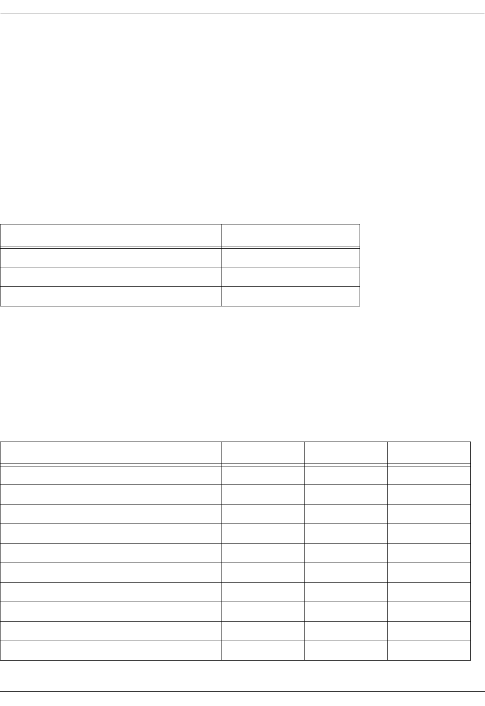
User Manual—Mobile Advantage Wireless Office (DWOS 1.0)
52 (80) 198 17-HRC104 201 PA9
the system. To assist in troubleshooting some failures, the CRE boards, RHs,
and Scanners have Light Emitting Diodes (LED). The LEDs, located on the
front of the boards or units for easy observation, provide indications of unit
status. All CRE boards have at least one power LED located at the top of the
board. The power LEDs display green when DC power is supplied to the
board.
The following tables describe specific LED indications of board and unit
statuses.
9.3.1 RH and Scanner LEDs
Visual indicators of RH or Scanner status are shown in Table 2.
9.3.2 CRE Boards Common LEDs
Visual indicators common to all RLU, DTU, and SPU boards statuses are
shown in Table 3.
Note: The common LED indicators also apply to the RLU board in slot three
of the main cabinet. The RLU board in slot three functions as a central
processor not a link board.
Table 2 Radio Head and Scanner LEDs
Radio Head and Scanner Status LED Indication
Powered on no application running Red
Booting Yellow
Working Green
Table 3 Common CRE Boards LEDs
CRE Board Status (RLU, DTU, and SPU) Error LED Status LED Que LED
No Software loaded (hardware default) Red
In Little Boot mode Yellow
Little Boot Failed Red Yellow
In Big Boot mode Green
Big Boot loading boot parameters Yellow Green
Big Boot loading application Green Green
Big Boot Failed Red Green
Blocked Fault detected Red Red
Board OK no ping (SPU and RLU boards) Green
Board OK and pinging (SPU and RLU boards) Green Flash
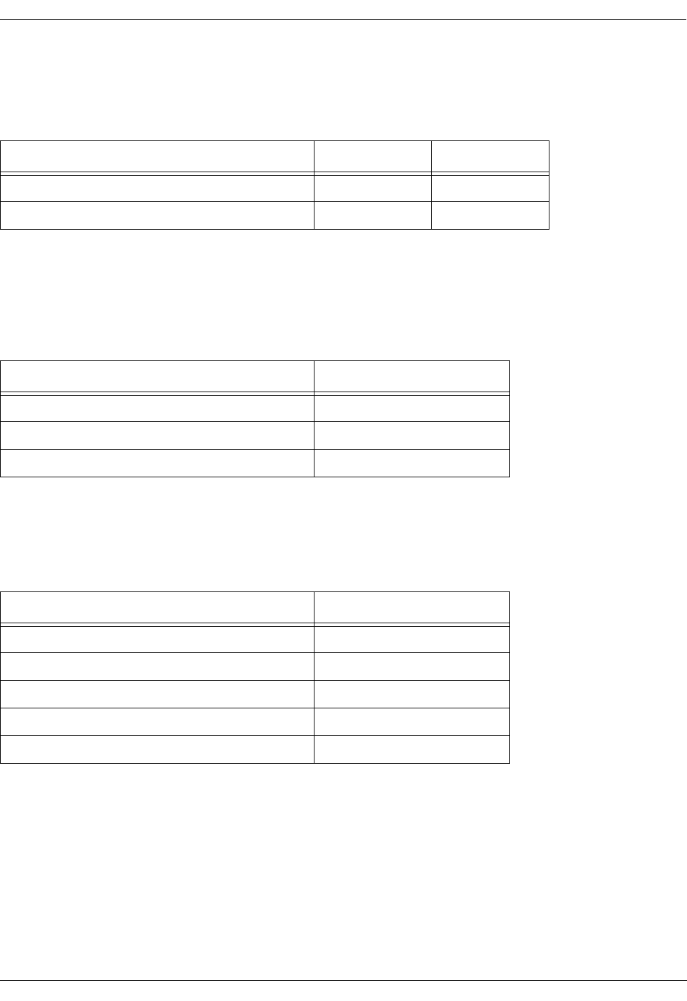
User Manual—Mobile Advantage Wireless Office (DWOS 1.0)
198 17-HRC104 201 PA9 53 (80)
9.3.3 DTU Board LEDs
Visual indicators specific to the DTU board statuses are shown in Table 4
9.3.4 SPU Boards LEDs
Visual indicators specific to the Digital Signal Processor (DSP) statuses on
each SPU board are shown in Table 5.
9.3.5 RLU Boards LEDs
Visual indicators specific to the RLU board statuses are shown in Table 6.
Note: The RLU board in slot three of the main cabinet does not have RLINK
cabling or statuses.
9.3.6 SWB LEDs
Table 4 DTU Board LEDs
DTU Board Status LED Number 1 LED Number 4
Powered on Green
Loss of Signal (LOS) Red
Table 5 SPU Board LEDs
DSP Status LEDs (one for each DSP)
No calls allocated
Active as DCCH Yellow
Active as DTC Green
Table 6 RLU Board LEDs
Status LED (one for each RLINK)
No signal since Boot
Loss of Signal (LOS) Red
Out of Frame (OOF) Red Flash
RLINK OK no pinging Green Flash
OK and pinging Green

User Manual—Mobile Advantage Wireless Office (DWOS 1.0)
54 (80) 198 17-HRC104 201 PA9
10 Software and Hardware Upgrades
Upgrading Mobile Advantage to implement new functions, hardware, or units
can require the loading of new software. Mobile Advantage guides the O&M
user when loading software.
Note: Always perform the replacement or upgrading of hardware and
software during periods of light traffic. When upgrading there is
always the possibility the newly installed hardware or software may
not function properly with Mobile Advantage. Be prepared to uninstall
an upgrade if necessary.
10.1 Hardware Upgrades
The installation of new hardware is typically plug and play (P&P). When new
hardware is installed in the CRE, the hardware is automatically detected and
activated. Installing most new CRE boards or replacing defective boards can
be done while the CRE is powered (hot swapping).
In the service area “Hardware Resources”, the user can create, browse, delete,
block, and unblock boards, links, and trunks. The user can also install and
modify software releases.
Note: For the SWB only, deactivate (block) the device before physically
removing it to prevent misleading traps from being generated.
All cables should be attached to CRE boards after installing. For example,
RLU boards should have the cables to the RHs connected after installation.
Installing the boards with the cables connected could cause a large current
surge to the RHs.
When upgrading or replacing an RH, Scanner, and most units, Mobile
Advantage loads new software automatically. The Mobility Server reads the
new configuration data from the CRE and activates the new hardware. RHs
and Scanners require a warm-up period before operating accurately.
The following Mobile Advantage units cannot be replaced with the plug and
play installation method:
•Replacement of the Mobility Server requires reinstallation of Mobile
Advantage software. Replacement of redundant units in the Mobility
Server can be done in the P&P manner with “hot swapping”.
Replacement of boards that are not redundant or capable of “hot
swapping” requires shutting down and powering OFF the Mobility
Server.
•The SWB has a configurable IP interface which must be initialized.
Replacing the SWB requires deleting the defective board and creating a
new board. This requires entering the IP address, along with other data,
of the SWB in the service area “Hardware Resources” selection “Board”.
•The CRE Power Module (CPM) and SYNC boards are not “hot
swappable”. Replacement of the CPM and SYNC boards in the CRE
effects all boards. Turn OFF power to the CRE when replacing the CPM
and SYNC boards.

User Manual—Mobile Advantage Wireless Office (DWOS 1.0)
198 17-HRC104 201 PA9 55 (80)
10.2 Upgrading From a One-Cabinet to a Two-Cabinet System
When performing the following procedure, use a printed copy of Chapter 11,
“Appendix A—Cabling and Connectors,” on page 58 of this manual.
Note: CRE auxiliary cabinets provide only expansion space for additional
RLU and Signal Processing Unit (SPU) boards. An auxiliary cabinet
requires only cabling for power, PE grounding, and any configured
RLU boards.
1. Unpack the CRE auxiliary cabinet and observe any indications of damage
in shipping. If damage is observed contact Ericsson or the supplier.
2. Inspect the shipping container contents and compare the shipping
material lists. Separate cables by part number.
3. Insert two mounting screws, supplied with the cabinet, in the top two
marked positions. Leave a space of one-quarter inch between the wall
and screw heads to allow the slots in the cabinet case to slip over the
screws when mounting.
Note: The position of the mounting screws for a wall-mounted auxiliary
cabinet should have been marked when the main cabinet was
installed. If the mounting screws positions for the auxiliary
cabinet were not marked use the mounting template provided with
the system.
4. Mount the auxiliary cabinet on the right side of the main cabinet by
setting the large slotted holes in the back case over the top screws and
slowly lowering until the studs slip into the slots.
5. Remove the front cabinet covers of the main and auxiliary cabinets.
6. Remove the auxiliary cabinet bottom cover.
7. Insert the two bottom screws in the auxiliary cabinet back case and
tighten all four cabinet mounting screws.
8. Connect the auxiliary cabinet case to Protective Earth (PE), using the
cables provided, as shown in Figure 9, Recommended CRE Power and
Grounding, on page 59.
9. Notify all users and shut down the Mobile Advantage system.
10. Turn OFF power to the main cabinet
11. Put on an ESD wrist strap and attach it to the ground wire braid on the
front of the CRE main cabinet.
12. Remove the boards in slots ten and eleven of the main cabinet. Place the
boards individually into ESD protective bags. Do not stack boards.
13. Remove the board in slot two of the auxiliary cabinet. Place the board
into the ESD protective bag. Do not stack boards.
14. Remove the terminating resistor packs in the backplane as shown in
Figure 7, CRE backplane interconnecting cables, on page 56.
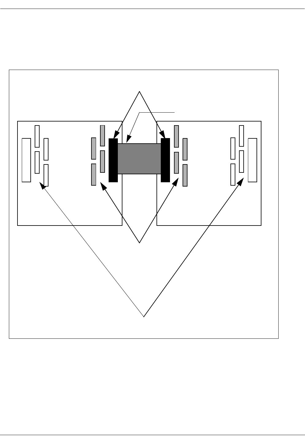
User Manual—Mobile Advantage Wireless Office (DWOS 1.0)
56 (80) 198 17-HRC104 201 PA9
Note: When connecting multiple cabinets, bus termination resistors
must be installed only at each end of the extended backplane
(cabling between cabinets). Resistors are contained in eight, 10
pin, Single in-line pack (SIP) resistor packs.
Figure 7 CRE backplane interconnecting cables
15. Remove the cover plates over the feed-through holes for the backplane
interconnecting ribbon cable. Feed-through holes will be on the right
side of the main cabinet and on the left side of the Auxiliary cabinets.
16. Install the spring fingers in the feed-through holes. Spring fingers protect
the backplane ribbon cable from abrasion in the feed-through holes.
17. Connect the backplane interconnecting ribbon cable, supplied with the
system, to the designated backplane connector in the main cabinet.
CRE
Main
Cabinet
CRE
Auxiliary
Cabinet
Remove these resistor packs
Leave these resistor packs in
Interconnecting Cable,
Backplane Connectors
Red line (indicating pin one)
toward top of cabinet

User Manual—Mobile Advantage Wireless Office (DWOS 1.0)
198 17-HRC104 201 PA9 57 (80)
18. Route the flat ribbon cable through the spring fingers surrounding the
feed-through holes.
19. Connect the flat ribbon cable to the designated backplane connector in
the auxiliary cabinet.
20. Replace the boards removed in Step 12. and Step 13.
21. If the auxiliary cabinet contains any RLU boards, connect an RLU cable
from the top telephony connector (DB-37) on the front panel of the first
available RLU board.
Note: The other end of the cable is connected to the top left side
connector of the punch block assigned to this RLU board. See
Step 3. of Chapter 4.3.1, “Installing Cables From The CRE to
RHs or Scanners,” on page 25
22. Connect an RLU cable from the bottom telephony connector on the front
panel of the first available RLU board of the auxiliary cabinet.
23. Connect the other end of the RLU cable to the connector on the bottom
right side of the designated punch block.
24. Repeat step Step 21. through Step 23. for the remaining RLU boards in
the CRE auxiliary cabinet.
25. Connect the -48 Vdc power source cables to the power connector on the
front of the CPM board in slot two of the auxiliary cabinet. Use Table 7,
“Power and PE Ground Cables”, on page 59, for connection information.
26. Remove the ESD wrist strap.
27. Replace the cabinet bottom and front covers.
28. Turn ON power to the main and auxiliary cabinets.
29. Restart the Mobile Advantage system.
30. End of procedure.
10.3 Software Upgrades
The software loading and backup functions are implemented in the O&M
client service areas. For the Mobility Server functions see the sub-menu
“Software Release.” For CRE functions see sub-menus “HW Resources,”
“Radio Infrastructure,” and “Browse SW Info.” (Copies of all the software are
stored in the Mobility Server.)
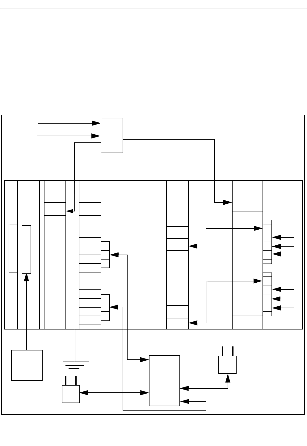
User Manual—Mobile Advantage Wireless Office (DWOS 1.0)
58 (80) 198 17-HRC104 201 PA9
11 Appendix A—
Cabling and Connectors
11.1 Overview
Figure 8, "Mobile Advantage Cables", shows an overview of internal and
external cabling for the Mobility Server, Cellular Radio Exchange, and Radio
Heads (RH). Scanners use the same cables as RHs. Auxiliary cabinets require
only the power, Protective Earth (PE) ground, and Radio Link (RLINK)
cabling.
Figure 8 Mobile Advantage Cables
Mobility Server
CPM
S
Y
N
C
RLU DTU SWB
RLU
RH
RH
P
u
n
c
h
RLU Cables
E1 Cable
CAT 5 Cable
-48 Vdc
Power
Power
Cables
B
l
o
c
k
CAT 5 Cable
Premise
PE
Ground
Cable
E1 Cable
12 3 4 9 1011
E1 or T1
Cables
External CAT 5 Cables
CAT 5 Cable
CAT 5 Cable
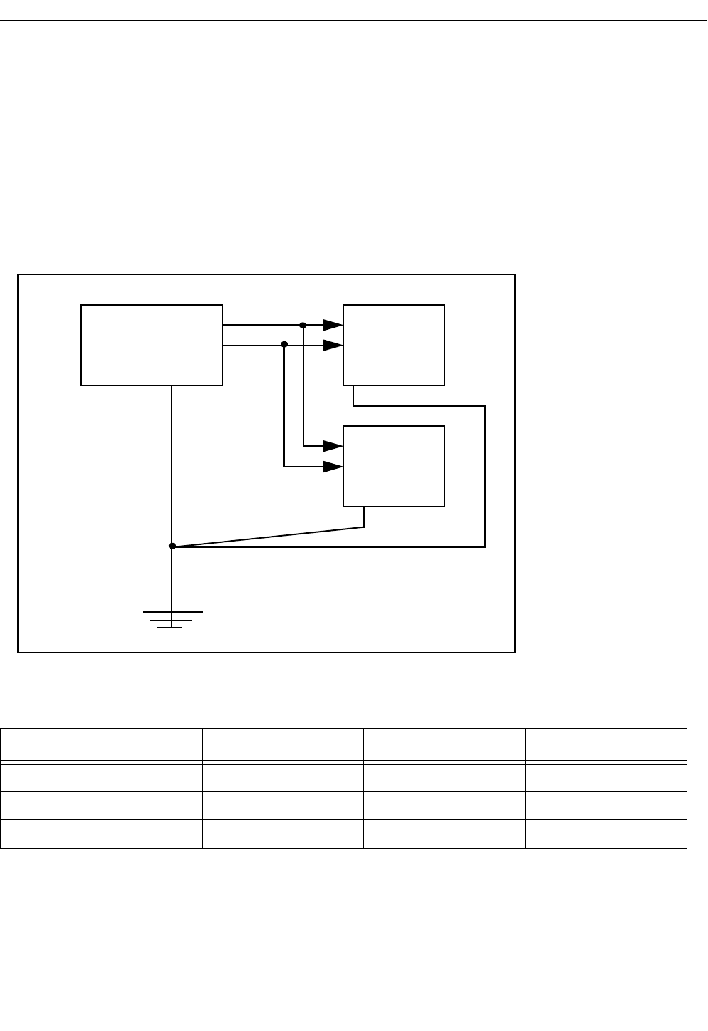
User Manual—Mobile Advantage Wireless Office (DWOS 1.0)
198 17-HRC104 201 PA9 59 (80)
11.2 -48 Vdc Power and Ground Cables
11.2.1 -48 Vdc Power Cables
CRE power (-48 Vdc) is supplied to the power connector on the front panel
of the CPM board in slot two of all cabinets. The power cables, supplied with
the system, must be used to comply with radiated emissions regulations.
Recommended Power and Grounding connections are shown in Figure 9.
Power and PE Grounding cable specifications are listed in Table 7.
Figure 9 Recommended CRE Power and Grounding
.
11.3 Backplane Interconnect Cable for a Two-Cabinet CRE
If the Mobile Advantage CRE configuration requires two-cabinets, use the
interconnecting flat ribbon cable supplied by Ericsson to connect the two
backplanes. Always use the CRE mounting template provided with the units
when mounting cabinets to assure the proper distance between cabinets.
Table 7 Power and PE Ground Cables
Cable Name Description Voltage Length
Power Black wire -48 Vdc 5 meters (16.5 feet)
Return Grey wire 0 Vdc 5 meters (16.5 feet)
Ground Braided wire PE Ground 5 meters (16.5 feet)
-48 VDC Power
Source
CRE Main
Cabinet
CRE Auxiliary
Cabinet
—
+
Power
Cables
Grounding
Cables
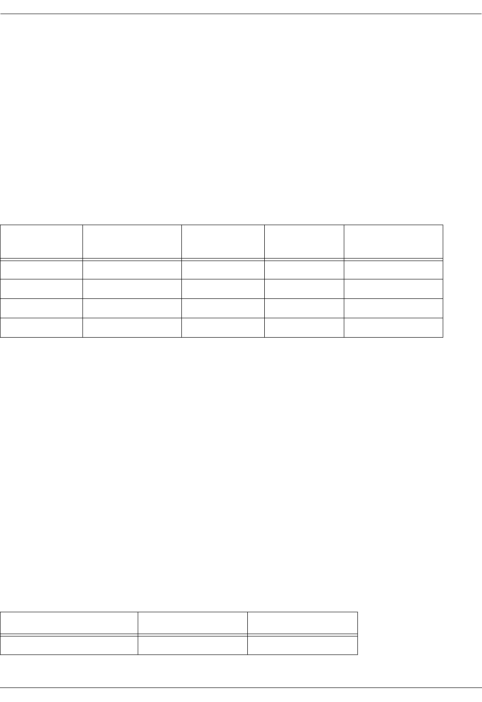
User Manual—Mobile Advantage Wireless Office (DWOS 1.0)
60 (80) 198 17-HRC104 201 PA9
11.4 RLU Ethernet Interface Cable (Slot Three Only)
The RLU in slot three of the main cabinet, functioning as the CRE central
processor, requires an Ethernet interface to the Mobility Server. A reverse
CAT 5 cable, supplied with the system, connects the RLU in slot three to the
Mobility Server. A reverse CAT 5 cable is designed as a direct link between
Ethernet nodes. With a reverse CAT5 cable the receive (RXD) and transmit
(TXD) wire pairs are swapped. The RLU reverse CAT 5 cable specifications
are shown in Table 8.
Note: The Ericsson CAT 5 cables, supplied with the system, must be used to
comply with radiated emissions regulations. Install the cable
connector end with the exposed shield to the RLU board and the end
with the covered shield to the Mobility Server port.
11.5 RLU Connections
Power and signal connections between the RHs or Scanners and the CRE are
routed through the cabling from RLU boards in slots four, five, seven, and
eight. Cabling consists of two parts; the RLU cables connect from the RLU
boards to the punch blocks and CAT 5 cables connect from the punch blocks
to RHs or Scanners. Two RLU to punch block cables are supplied with the
system for each configured RLU board.
11.5.1 Punch Block to Radio Heads (RH) or Scanners Cabling
The CAT 5 cables going to the punch blocks are supplied by the customer.
Ericsson recommends using any unshielded, 24-AWG, 4-pair, solid
conductor CAT 5 cables. A recommended CAT 5 cable type for this use is
shown in Table 9.
Note: Cables that are routed through ceilings or plenums must be rated for
fire safety. The applicable cable plenum specifications are defined in
NEC CMP and CSA PCC FT4/FT6.
Table 8 RLU Reverse CAT 5 Cable Signals and Pin Numbers (Slot Three Only)
Signal Name at
Mobility Server RJ-45 Pin Number
Mobility Server Suggested
Wire Color Signal Name at
RLU Board RJ-45 Pin Number
RLU Board
RXD+ 1 Blue TXD+ 3
RXD- 2 White/Blue TXD- 6
TXD+ 3 Orange RXD+ 1
TXD- 6 Orange/White RXD- 2
Table 9 Punch Block to RHs or Scanners Cables
Montrose Part Number Rating Connector
CBL 8040-4 Non-plenum RJ-45

User Manual—Mobile Advantage Wireless Office (DWOS 1.0)
198 17-HRC104 201 PA9 61 (80)
Using the recommended cables allow the RHs or Scanners to be located up to
1600 meters (5280 feet) from the CRE. RHs located less than 800 meters
(2640 feet) from the CRE receive power from the RLU boards through the
CAT 5 cables. For Scanners located up to 1200 meters (3960 feet) from the
CRE, the RLU boards also supply the power through the CAT 5 cables.
RHs and Scanners can be located up to a maximum of 1600 meters from the
CRE if powered from a 24 Vdc converter. The 24 Vdc converters require 115
Vac outlets nearby.
Note: If necessary, other types of twisted pair cable may be used. However,
using lower quality cable will result in shorter distance capabilities.
Use of any cable type except those recommended requires an
evaluation of that link by Ericsson.
Figure 10 is an overview of RLU cabling from a representative RLU board to
RH or Scanners. The central point for connections is the punch block. See
Table 10 for connection information and signal names on the CAT 5 cables.
CBL 8041-4 Plenum RJ-45
Table 9 Punch Block to RHs or Scanners Cables
Montrose Part Number Rating Connector
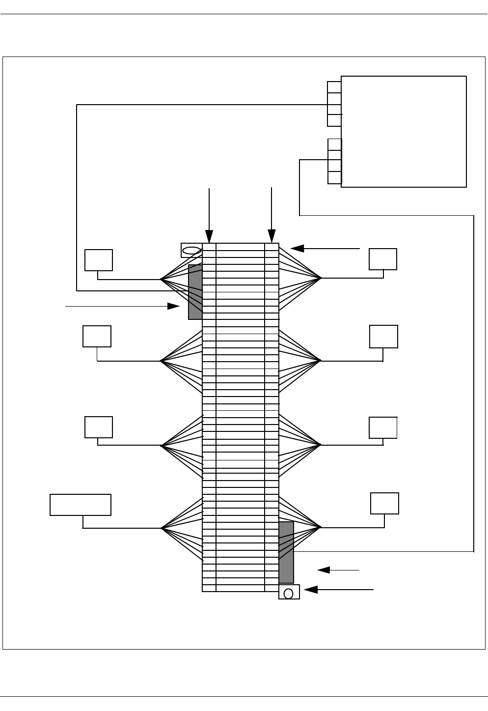
User Manual—Mobile Advantage Wireless Office (DWOS 1.0)
62 (80) 198 17-HRC104 201 PA9
Figure 10 Punch Block cabling overview
Row 1
Left Right
Punch Block
RH1
RH2
RH3
RH4
RH5
RH6
RH7
RH8
RH6
RH5
RH8
RH7
Right Telco
connector
RLU Cable
RLU Cable
Front view
Row 50
RH2
RH1
Scanner
RH3
NOTE: Scanners can be
connected to any RLU.
Left Telco
connector
RLU Board

User Manual—Mobile Advantage Wireless Office (DWOS 1.0)
198 17-HRC104 201 PA9 63 (80)
Table 10 RLU CAT 5 Cables From Punch Block to RHs or Scanners Signals and Pins
Radio Head Signal Name at
Radio Head RJ-45 Connector
Pin Number Punch Block
Connection Suggested
Wire Color
1
RLINK_RXRING 1 Left 1 White/Green
RLINK_RXTIP 2 Left 2 Green
RLINK_TXTIP 5 Left 3 White/Blue
RLINK_TXRING 4 Left 4 Blue
Left 5
Left 6
main_V- 3 Left 7 White/Orange
main_V- 6 Left 8 Orange
main_V- 7 Left 9 White/Brown
main_V- 8 Left 10 Brown
Left 11
Left 12
2
RLINK_RXRING 1 Left 13 White/Green
RLINK_RXTIP 2 Left 14 Green
RLINK_TXTIP 5 Left 15 White/Blue
RLINK_TXRING 4 Left 16 Blue
Left 17
Left 18
main_V- 3 Left 19 White/Orange
main_V- 6 Left 20 Orange
main_V- 7 Left 21 White/Brown
main_V- 8 Left 22 Brown
Left 23
Left 24

User Manual—Mobile Advantage Wireless Office (DWOS 1.0)
64 (80) 198 17-HRC104 201 PA9
3
RLINK_RXRING 1 Left 25 White/Green
RLINK_RXTIP 2 Left 26 Green
RLINK_TXTIP 5 Left 27 White/Blue
RLINK_TXRING 4 Left 28 Blue
Left 29
Left 30
main_V- 3 Left 31 White/Orange
main_V- 6 Left 32 Orange
main_V- 7 Left 33 White/Brown
main_V- 8 Left 34 Brown
Left 35
Left 36
4
RLINK_RXRING 1 Left 37 White/Green
RLINK_RXTIP 2 Left 38 Green
RLINK_TXTIP 5 Left 39 White/Blue
RLINK_TXRING 4 Left 40 Blue
Left 41
Left 42
main_V- 3 Left 43 White/Orange
main_V- 6 Left 44 Orange
main_V- 7 Left 45 White/Brown
main_V- 8 Left 46 Brown
Table 10 RLU CAT 5 Cables From Punch Block to RHs or Scanners Signals and Pins
Radio Head Signal Name at
Radio Head RJ-45 Connector
Pin Number Punch Block
Connection Suggested
Wire Color

User Manual—Mobile Advantage Wireless Office (DWOS 1.0)
198 17-HRC104 201 PA9 65 (80)
5
RLINK_RXRING 1 Right 1 White/Green
RLINK_RXTIP 2 Right 2 Green
RLINK_TXTIP 5 Right 3 White/Blue
RLINK_TXRING 4 Right 4 Blue
Right 5
Right 6
main_V- 3 Right 7 White/Orange
main_V- 6 Right 8 Orange
main_V- 7 Right 9 White/Brown
main_V- 8 Right 10 Brown
Right 11
Right 12
6
RLINK_RXRING 1 Right 13 White/Green
RLINK_RXTIP 2 Right 14 Green
RLINK_TXTIP 5 Right 15 White/Blue
RLINK_TXRING 4 Right 16 Blue
Right 17
Right 18
main_V- 3 Right 19 White/Orange
main_V- 6 Right 20 Orange
main_V- 7 Right 21 White/Brown
main_V- 8 Right 22 Brown
Right 23
Right 24
Table 10 RLU CAT 5 Cables From Punch Block to RHs or Scanners Signals and Pins
Radio Head Signal Name at
Radio Head RJ-45 Connector
Pin Number Punch Block
Connection Suggested
Wire Color

User Manual—Mobile Advantage Wireless Office (DWOS 1.0)
66 (80) 198 17-HRC104 201 PA9
11.6 SwitchBoard (SWB)
11.6.1 SWB Ethernet Interface
The Ethernet connection on the SWB uses a reverse CAT 5 cable with an
RJ-45 connector. The reverse CAT 5 cable connects the SWB in the CRE to
the Mobility Sever. A reverse CAT 5 cable is designed as a direct link
7
RLINK_RXRING 1 Right 25 White/Green
RLINK_RXTIP 2 Right 26 Green
RLINK_TXTIP 5 Right 27 White/Blue
RLINK_TXRING 4 Right 28 Blue
Right 29
Right 30
main_V- 3 Right 31 White/Orange
main_V- 6 Right 32 Orange
main_V- 7 Right 33 White/Brown
main_V- 8 Right 34 Brown
Right 35
Right 36
8
RLINK_RXRING 1 Right 37 White/Green
RLINK_RXTIP 2 Right 38 Green
RLINK_TXTIP 5 Right 39 White/Blue
RLINK_TXRING 4 Right 40 Blue
Right 41
Right 42
main_V- 3 Right 43 White/Orange
main_V- 6 Right 44 Orange
main_V- 7 Right 45 White/Brown
main_V- 8 Right 46 Brown
Table 10 RLU CAT 5 Cables From Punch Block to RHs or Scanners Signals and Pins
Radio Head Signal Name at
Radio Head RJ-45 Connector
Pin Number Punch Block
Connection Suggested
Wire Color

User Manual—Mobile Advantage Wireless Office (DWOS 1.0)
198 17-HRC104 201 PA9 67 (80)
between Ethernet nodes. With a reverse CAT5 cable the receive (RXD) and
transmit (TXD) wire pairs are swapped. The specifications for the cable
connecting the SWB to the Mobility Server are shown in Table 11.
Note: The Ericsson CAT 5 cables supplied with the system must be used to
comply with radiated emissions regulations. Install the cable
connector end with the exposed shield to the SWB and the end with
the covered shield to the Mobility Server port
11.6.2 SWB E1/T1 PCM Interface
The CRE SWB can support six external T1 or E1 connections to PBXs. The
specified Ericsson cables, with shielded connectors, are supplied with the
system. The Ericsson cables must be used when connecting to the SWB to
comply with radiated emissions regulations. Two E1 cables are supplied and
connected from PCM ports one and five of the SWB to the DTU. For
information about the DTU cables see Table 14, “SWB to DTU E1 Signal
Names and Pin Numbers”, on page 71.
The PCM cables in the following list are intended for use when the CRE is
located in the same room as a PBX or other system. When the location of a
PBX or other system requires extension cabling, the cabling must be
connected to the Ericsson supplied cables to comply with radiated emissions
regulations.
Note: The T1 or E1 cables supplied by Ericsson are not rated for plenum or
ceiling use. When adding any extension cables in ceilings or plenums,
the cables must meet fire retardant specifications.
Table 11 SWB to Mobility Server Reverse CAT 5 Cable Signals and Pin Numbers
Signal Name at
Mobility Server RJ-45 Pin Number
Mobility Server Suggested
Wire Color Signal Name at
SWB Board RJ-45 Pin Number
SWB
RXD+ 1 Blue TXD+ 3
RXD- 2 White/Blue TXD- 6
TXD+ 3 Orange RXD+ 1
TXD- 6 White/Orange RXD- 2

User Manual—Mobile Advantage Wireless Office (DWOS 1.0)
68 (80) 198 17-HRC104 201 PA9
Use the following specifications along with Figure 11, "SWB Interface for T1
or E1 Connections", to determine the signal names, pin numbers, and ports of
the Ericsson supplied cables:
•For T1 connections use Table 12, "SWB T1 Signal Names and Pin
Numbers". Connect T1 PBX links to the following SWB PCM ports:
-
Connect PBX link one to SWB PCM port two.
-
Connect PBX link two to SWB PCM port six.
-
Connect PBX link three to SWB PCM port three.
-
Connect PBX link four to SWB PCM port seven.
-
Connect PBX link five to SWB PCM port four.
-
Connect PBX link six to SWB PCM port eight.
•For E1 connections use Table 13, "SWB E1 Signal Names and Pin
Numbers".
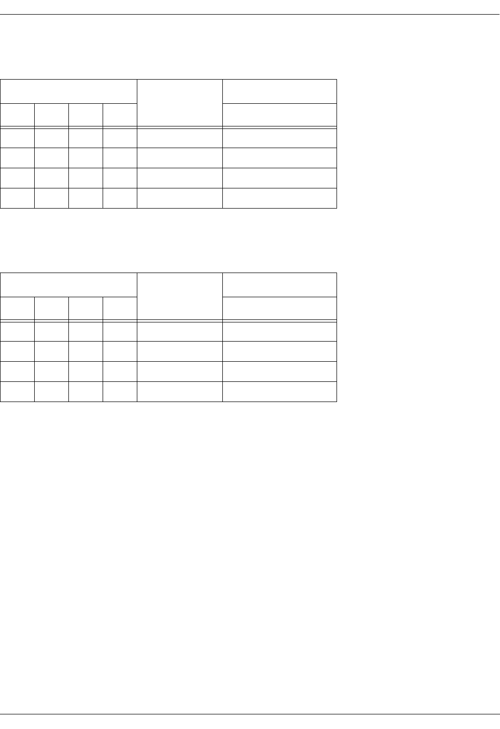
User Manual—Mobile Advantage Wireless Office (DWOS 1.0)
198 17-HRC104 201 PA9 69 (80)
11.6.2.1 SWB T1 Cable Specifications
11.6.2.2
Table 12 SWB T1 Signal Names and Pin Numbers
Interface Pin Numbers Receive (RX) or
Transmit (TX)
1 2 3 4 RJ-45 Pin Number
C02 C10 C18 C26 TX + From SWB 4
C04 C12 C20 C28 TX - From SWB 5
C06 C14 C22 C30 RX + To SWB 1
C08 C16 C24 C32 RX - To SWB 2
Table 13 SWB E1 Signal Names and Pin Numbers
Interface Pin Numbers Receive (RX) or
Transmit (TX)
1 2 3 4 DB-15 Pin Number
C02 C10 C18 C26 TX + From SWB 3
C04 C12 C20 C28 TX - From SWB 11
C06 C14 C22 C30 RX + To SWB 1
C08 C16 C24 C32 RX - To SWB 9
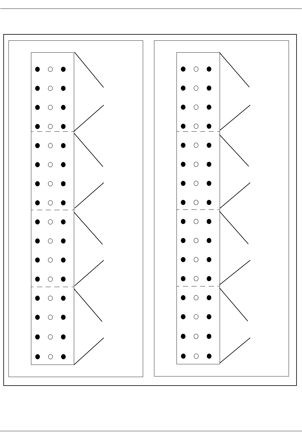
User Manual—Mobile Advantage Wireless Office (DWOS 1.0)
70 (80) 198 17-HRC104 201 PA9
Figure 11 SWB Interface for T1 or E1 Connections
1
2
3
4
5
6
7
8
9
10
11
12
13
14
15
16
17
18
19
20
21
22
23
24
25
26
27
28
39
30
31
ABC
32
Interface Cable
Interface Cable
Interface Cable
Interface Cable
to DTU Board
External
External
External
1
2
3
4
5
6
7
8
9
10
11
12
13
14
15
16
17
18
19
20
21
22
23
24
25
26
27
28
39
30
31
ABC
32
Interface Cable
Interface Cable
Interface Cable
Interface Cable
to DTU Board
External
External
External
SWB Interface SWB Interface
Top Connector Bottom Connector
PCM Port One
PCM Port Two
PCM Port Five
PCM Port Six
PCM Port Seven
PCM Port Eight
PCM Port Three
PCM Port Four
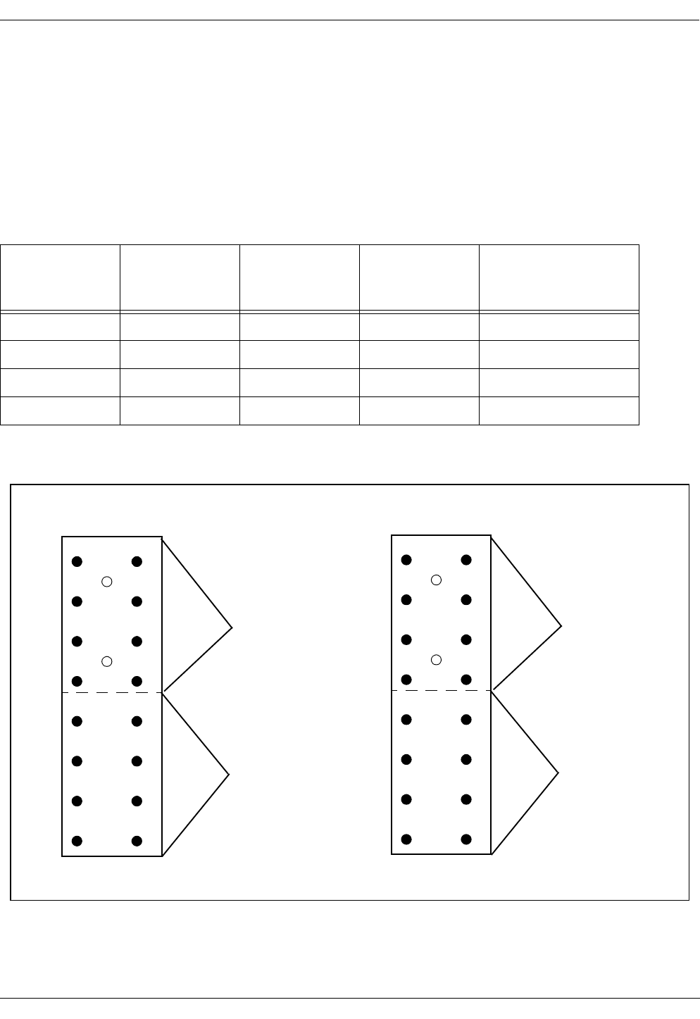
User Manual—Mobile Advantage Wireless Office (DWOS 1.0)
198 17-HRC104 201 PA9 71 (80)
11.6.3 SWB to DTU cables
Two E1 cables are supplied by Ericsson to connect the DTU board, in slot
nine of the CRE, to the SWB in slots 10 and 11. The E1 cable from the top
connector on the DTU board connects to PCM port one on the SWB. The E1
cable from the bottom connector on the DTU board connects to PCM port five
on the SWB. Use the following cable specifications in Table 14, along with
Figure 11, "SWB Interface for T1 or E1 Connections", and Figure 12, "DTU
E1 Connector Pin Numbers", to determine the signal names and pin numbers.
Figure 12 DTU E1 Connector Pin Numbers
Table 14 SWB to DTU E1 Signal Names and Pin Numbers
SWB Interface
Pin Numbers
Receive (RX) or
Transmit (TX)
SWB
Receive (RX) or
Transmit (TX)
DTU
DTU Interface
Pin Numbers Length
C02 TX + From SWB RX + To DTU A14 150 mm (6 inches)
C04 TX - From SWB RX - To DTU C16
C06 RX + To SWB TX + From DTU A10
C08 RX - To SWB TX - From DTU C12
2
3
4
5
6
7
8
9
10
11
12
13
14
15
16
1ABC
75 ohm interface
Interface Cable
not used
to SWB
2
3
4
5
6
7
8
9
10
11
12
13
14
15
16
1ABC
75 ohm interface
Interface Cable
not used
to SWB
Top Connector Bottom Connector

User Manual—Mobile Advantage Wireless Office (DWOS 1.0)
72 (80) 198 17-HRC104 201 PA9
12 Appendix B—
Acronyms and Abbreviations
10BASE-T—10Mbit/s Ethernet system using twisted pair cables. The twisted
pair only supports point-to-point connections. To connect several terminals a
repeater hub is required.
850 MHz—The hyper band that is called cellular today (defined in
TDMA-136.2-A table 2.1.1.1.1-1). The frequency bands at 850 MHz are
named a, a', a'' and b, b'. Normally one cellular operator owns the license to
operate on a-band (including a' and a'') or b-band (including b').
1900 MHz—The hyper band called PCS today (defined in TDMA-136.2-A
table 2.1.1.1.2-1). The frequency bands at 1900 MHz are named A, B, C, D,
E and F. Normally one cellular operator owns the license to operate on one of
these bands.
ACELP—The speech coding algorithm used in Mobile Advantage is defined
as an alternate speech coder algorithm in TDMA-136.2-A 2.1.3.3.2. (The
actual description is in IS-641). The ACELP codec is considered to have a
better speech quality than VSELP. Another name for the ACELP coder is
EFR.
A-key—The input number that the authentication process uses as one of the
input to the Auth_Signature algorithm. See TDMA-136 for details.
Allowed-list—The frequencies that Mobile Advantage is allowed to use. If no
allowed-list is entered Mobile Advantage will consider the whole frequency
band, except the disallowed-list, as being on the allowed-list. Allowed list +
disallowed list = the whole frequency band.
AMPS—Advanced Mobile Phone System. The analog system which operates
on 850 MHz.
ANSI-41: Cellular Radio Telecommunications Intersystem Operations, the
TIA specification of how the VLR, HLR and MSC communicate.
Barred—The user is not allowed to use the system. In the cellular system this
can be used when the user has not paid his bills, but the cellular operator wants
to enable calls as soon as the money arrives. In Mobile Advantage we can use
this to define a user in the cellular HLR to provide for authentication and
voice privacy in Mobile Advantage, but barr him from making calls in the
cellular system.
BOOTP—The Bootstrap Protocol, BOOTP, is a UDP/IP based protocol,
which allows a booting client to configure itself dynamically and without user
supervision. BOOTP provides a means to notify a client of its assigned IP
address, the IP address of the boot Server host, and the name of the file to be
loaded into the memory and executed.
CAT 5 cable—Category 5 cable for Ethernet and other interfaces. Twisted
signal pair, non-shielded, 22 AWG or 24 AWG wire size. Used in Ethernet
interfaces and cabling to RHs and Scanners.
CLI—Calling Line Identification
CRE—Cellular Radio Exchange. The central part of the Mobile Advantage
radio infrastructure.

User Manual—Mobile Advantage Wireless Office (DWOS 1.0)
198 17-HRC104 201 PA9 73 (80)
D-AMPS—Digital Advanced Mobile Phone System. The digital system
described in TDMA-136.
DCCH—Digital Control Channel, as defined in TDMA-136.1.
DID—Direct In Dialing.
Direct in dialing—The possibility to dial the Mobile Advantage user's office
number directly from the public network. No attendant is involved in this
process.
Disallowed-list—The frequencies that Mobile Advantage is not allowed to
use. The analog control channels or the frequencies used in the neighboring
cellular sites. If no disallowed list is entered in Mobile Advantage the whole
frequency band is considered to be allowed. Allowed list + disallowed list =
the whole frequency band.
DTC—Digital Traffic Channel, as defined in TDMA-136.2.
DTMD—Dual Tone Multi Frequency. Tone signaling method used in
telecommunications.
DUN—DWOS User Number
DWOS—Digital Wireless Office Services (product unit), sometimes
synonymous with Mobile Advantage.
DWOS Mobile Stations—A Mobile Advantage Mobile Station compatible
with TDMA-136. Each Mobile Station is defined in one HLR.
Note: Not all TDMA-136 compatible Mobile Stations are fully functional
within the Mobile Advantage area.
Encryption—The process of applying a secret sequence to data in order to
protect it from eavesdropping (voice privacy as defined in TDMA-136).
Erlang—A measure of traffic in telecommunication systems.
Ethernet—A group of cabling systems for creating a data-bus in Local Area
Networks. Ethernet also includes a protocol for handling the transmission on
the Ethernet bus. On top of the Ethernet other protocols are used, like the
TCP/IP suite. The Mobile Advantage O&M Client can access the Mobility
Server using Ethernet in a LAN/WAN.
FTP—File Transfer Protocol, FTP, supports down loading of software files
from the O&M Client to the Mobility Server. The O&M Client can fetch the
file, containing the measurement data, from the Mobility Server by using
FTP. FTP is also used during start up of the RI to transfer configuration
information from the Mobility Server to RI.
GOS—Grade of service.
Grade of service—The percent of the call set-up attempts that are blocked due
to congestion.
HLR —Home Location register—Each Mobile Advantage mobile phone is
defined in one HLR. Some mobile phone data is stored in the HLR, for
example, the current location of the mobile phone and its authentication data.
HTTP—The user interface for the O&M functions is WWW pages using

User Manual—Mobile Advantage Wireless Office (DWOS 1.0)
74 (80) 198 17-HRC104 201 PA9
Hyper Text Transfer Protocol as a high level protocol to communicate with
the Mobility Server.
IP—The Internet Protocol is used on the network layer to define addresses
and locally to address the CRE.
ISDN—Integrated Services Digital Network.
LAN—Local Area Network.
MIN—Mobile Station Identification Number.
MO—Managed Object
Mobile—The name we use when talking about the mobile phone terminals
used within Mobile Advantage.
Mobile Advantage coverage area—The area in which the radio signal quality
to or from Mobile Advantage is good enough to setup and maintain a
connection between the Mobile Advantage system and a Mobile Advantage
mobile phone.
Mobile phone—Synonym of mobile.
Mobile terminal—Synonym of mobile.
Mobility Server—A common name for the system entity that consists of the
SwitchBoard and the NT-Server.
MobServer—Short for Mobility Server.
MWI—Message Waiting Indicator.
NT-Server—A PC with the Windows NT operating system running on it.
NFS—Network File System. NFS is used by the RI to store and retrieve
configuration data, performance measurement data and other data which is
stored on the hard disk in the Mobility Server.
O&M—Operation, Administration, and Maintenance. Configurables in
Mobile Advantage are handled by the O&M software residing on the Mobility
Server.
PBX—Private Branch Exchange. Mobile Advantage is connected to a PBX
by a Primary Rate Interface (PRI). The PBX provides routing connections to
the PSTN.
PSTN—Public Switched Telephony Network. The PSTN has no direct
contact with a Mobile Advantage. The PBX connects external PSTN calls to
Mobile Advantage.
PLMN-MSC—Public Land Mobile Network - Mobile Switching Center. The
MSC is not in direct contact with Mobile Advantage but can connect calls
through the PSTN.
PSID—Private System Identification. The name allocated to a private system.
The license owner allocates a PSID to a Mobile Advantage installation.
Registration—The process of a mobile phone informing Mobile Advantage
that the user is now within the Mobile Advantage coverage area.

User Manual—Mobile Advantage Wireless Office (DWOS 1.0)
198 17-HRC104 201 PA9 75 (80)
Reverse CAT 5 cable—A cable designed as a direct link between Ethernet
nodes. With a reverse CAT5 cable the receive (RXD) and transmit (TXD)
wire pairs are swapped.
RH—Radio Head.The distributed part of the Mobile Advantage radio
infrastructure, containing e.g. the RF-parts.
RI—Radio Infrastructure
RLINK—The link between the CRE and a RH or Scanner.
RNC-data—The data containing information necessary for the Radio
Network Control algorithms.
Roaming—When the mobile phone is moving between different parts of the
cellular system and between different cellular systems connected in a
network, or to a Mobile Advantage, and the cellular user still is able to place
and receive calls.
RSID—Residential System Identification.
Short Mobile Advantage number—The short number (four or five-digits) that
other Mobile Advantage users or PBX users can dial to reach a Mobile
Advantage user.
SID—System Identification. The name allocated to the Public System.
Site Survey tool—A tool that helps the installer to plan how many Radio
Heads the customers installation requires and where the Radio Heads should
be placed.
SMS—Short Message Service.
SNMP—Simple Network Management Protocol. An Internet protocol for
managing information on nodes served by agents.
SW—software.
System Entities—The significant parts of the Wireless Office System. I.e.
Mobility Server, O&M Server, Cellular Radio Exchange and Radio Heads.
TCP—The Transmission Communication Protocol is used on the transport
layer according to the 4-Layer Protocol model.
TCP/IP—Transport Control Protocol/Internet Protocol. A family of protocols
developed to allow computers to share resources around a network. Some
provide low-level functions needed for many applications. These include IP,
TCP and UDP. Other functions are FTP (File Transfer Protocol), TELNET
(remote login) and mail.
TDMA-136—The TIA standard which defines the air interface that Mobile
Advantage is using.
Terminal—Synonym of mobile phone.
Terminating call set-up—The call is set-up when the Mobile Advantage user
answers the phone after having been alerted by a ring signal.
TIA—Telecommunications Industry Association, the organization that
defines the TDMA-136.

User Manual—Mobile Advantage Wireless Office (DWOS 1.0)
76 (80) 198 17-HRC104 201 PA9
UDP—User Datagram Protocol. A protocol that runs on top of IP. Like TCP,
but with no transmission control or re-sending. Requires much less resources
than TCP.
User—Synonym for Mobile Advantage user.
VLR—Visitors Location Register, a register in which information of the
status and location of all active mobile phones within the coverage area of the
cellular system is stored.
VMS—Voice Mail System
Voice privacy—The process of applying encryption on the voice channel to
make it more difficult to eavesdrop a connection.
WOS SS7—Mobile Advantage access to Signaling System 7 network

User Manual—Mobile Advantage Wireless Office (DWOS 1.0)
198 17-HRC104 201 PA9 77 (80)
13 Appendix C—Mobile Advantage Unit Specifications
This section provides specifications, including power and temperature
requirements, for Mobile Advantage units. For information about Mobile
Advantage cables see, "Appendix A—Cabling and Connectors," on page 58.
13.1 Mobility Server
The Mobility Server is based upon a Microsoft Windows NT™ server with
redundant drives, fans and power supplies. A four-port Network Interface
Card (NIC), two serial ports, and an optional internal modem provide external
access and communications. The Mobility Server performs all call control,
service control, and O&M functions in the Mobile Advantage system.
The Mobility Server is powered by redundant -48 Vdc power supplies.
Indications of loss of a single power supply, fan module, or hard drive, and
other failures are propagated to the Mobile Advantage event log and can be
configured to signal audibly.
The temperature range where the CRE and Mobility Server are located must
be between +5°C and +40°C and relative humidity may vary between 15%
and 80%.
13.2 CRE Specifications
Both the main and auxiliary cabinets have the same part numbers. When an
auxiliary cabinet is connected to a main cabinet the slot assignments are
automatically configured. For example, Mobile Advantage recognizes slot
time in the main cabinet is reserved for the DTU board, but slot nine in the
auxiliary cabinet can be used by SPU or RLU boards.
13.2.1 CRE Cabinet Dimensions
Table 15, “CRE Cabinet Specifications”, is shown for information only. A
template is included with the cabinets for positioning the mounting screws.
The weight given is for a maximally equipped cabinet with cables attached.
Note: The weight of a CRE cabinet requires mounting to a panel that is
secured to wall studs.
13.2.2 CRE Configuration Example
Table 16 describes an example of a maximally configured CRE with two
loaded cabinets. The CRE in this example is configured to process a
maximum of 60 simultaneous calls. Other configurations are possible as long
Table 15 CRE Cabinet Specifications
Height Width Depth Weight
432 mm (17.25 inches) 256 mm (10.24 inches) 304 mm (12.16 inches) 17kg (37.4 pounds)
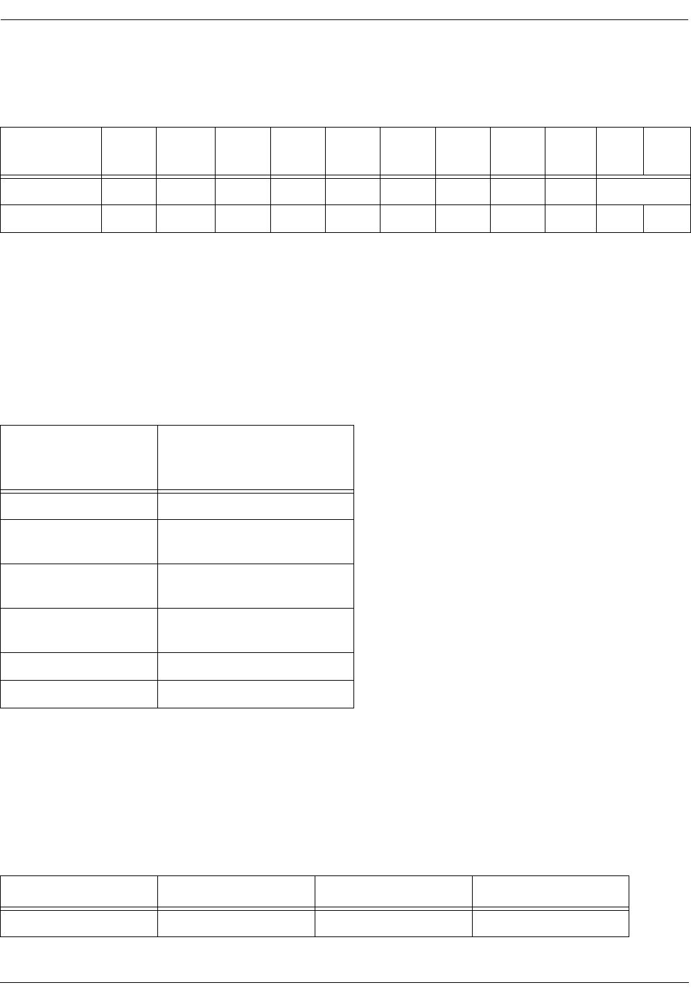
User Manual—Mobile Advantage Wireless Office (DWOS 1.0)
78 (80) 198 17-HRC104 201 PA9
as the board type and slot assignments conform to the requirements listed in
Table 17, “CRE board numbers and slot assignments”.
13.2.3 CRE Board Assignments
Table 17, “CRE board numbers and slot assignments”, lists the allowable
board configurations for the Mobile Advantage.
Note: *When inserted in slot three of the main cabinet, the RLU board
functions as a central processor. No RHs or Scanners can be connected
to the RLU in slot three of the main cabinet.
13.3 Radio Heads and Scanners
Radio Heads (RH) and Scanners are mounted vertically on internal walls in
the Mobile Advantage coverage area. Each RH provides five transceivers for
air interface communications with mobile phones using the TDMA-136
protocol. Mounting templates are provided with the system.
Table 16 Mobile Advantage CRE Maximum Configuration example
Slots
Cabinets 12 34567891011
main SYNC CPM RLU RLU RLU SPU RLU RLU DTU SWB
Auxiliary CPM SPU SPU SPU SPU SPU SPU SPU
Table 17 CRE board numbers and slot assignments
Board Name Allowed in slot number in:
Main Cabinet (M)
Auxiliary Cabinet (A)
SYNC M— 1
CPM M— 2
A— 2
RLU M— 3*, 4, 5, 7, 8
A— 4, 5, 7, 8
SPU M— 4, 5, 6, 7, 8
A— 3, 4, 5, 6, 7, 8, 9, 10, 11
DTU M— 9
SWB M— 10 and 11
Table 18 RH and Scanners Dimensions
Height Width Depth Weight
233 mm (9.32 inches) 362 mm (14.48 inches) 57 mm (2.28 inches) 5kg (11 pounds)

User Manual—Mobile Advantage Wireless Office (DWOS 1.0)
198 17-HRC104 201 PA9 79 (80)
13.4 System power requirements
Power requirement for the Mobility Advantage system can be calculated
based on the sum of the individual components in the system. Table 19,
“System Power Caculations” lists the power drain for each system unit.
Table 19 System Power Caculations
System unit Power drain
(per unit) Maximum units
allowed
Mobility Server 425 Watts 1
CRE 125 Watts 2 (Main & Auxiliary)
RH/Scanner 37.5 Watts 32

User Manual—Mobile Advantage Wireless Office (DWOS 1.0)
80 (80) 198 17-HRC104 201 PA9
14 Appendix D—Recommended tools
14.1 General
The following list of tools, software, and test equipment are recommended to
install and maintain Mobile Advantage. Tools that are part of the conventional
installers tool kit, such as soldering irons, are not specified in this section. All
tools, software, and test equipment, can be purchased locally or ordered from
Ericsson.
Note: Warning: Drilling machines and soldering irons must be
double-insulated.
Replacement boards and units should be stored at a central location. The
technician should bring the appropriate spare boards and equipment to the
customer site based on the type of service call.
•Laptop PC—Minimum specifications:
-
Hardware—Pentium processor; one gigabyte hard drive; RAM size
32 Megabytes; CDROM; 3.5 floppy drive; PCMIA Modem speed 28
Kilobytes; PCMIA Serial I/O; PCMIA Ethernet communications
board
-
Software—Windows NT 4.0, Remote Access Software (RAS)
•Remote Access Software (RAS)
•Plastic or cardboard box for temporary storage of boards
•ESD wrist straps with alligator clip connector
•ESD packaging bags for boards (quantity eight)
•Punch tools compatible with punch block types used
•Test cords compatible with punch block types used
•Mobile phone, TDMA-136 compatible