HARRIS MBS800B075 OpenSky 800 MHz Base Station User Manual Manual
Harris Corporation OpenSky 800 MHz Base Station Manual
HARRIS >
Manual

Rhein Tech Laboratories, Inc. Client: M/A-COM, Inc.
360 Herndon Parkway Model: OpenSky 800 MHz Base Station
Suite 1400 ID’s: BV8MBS800B075/3670A-MBS800B
Herndon, VA 20170 Standards: FCC Part 90/IC RSS-119
http://www.rheintech.com Report #: 2008072
38 of 62
Appendix K: User Manual
Please refer to the following pages.

Installation Manual
MM102225V1
Rev. B, Jul-05
Base Station/Tower Site

MM102225V1, Rev. B
2
MANUAL REVISION HISTORY
REV DATE REASON FOR CHANGE
A 2003 Initial release.
B Jul. 2005 Changed Accuracy Test, Step 7, added Caution added footnote.
M/A-COM Technical Publications would particularly appreciate feedback on any errors that might be found in
this document, and suggestions on how it could be improved. Submit your comments and suggestions to:
Wireless Systems Business Unit
M/A-COM, Inc.
Technical Publications
221 Jefferson Ridge Parkway
Lynchburg, VA 24501
fax (434) 455-6851
techpubs@tycoelectronics.com
CREDITS
OpenSky is a registered trademark of M/A-COM, Inc.
MATE-N-LOK is a registered trademark of Tyco Electronics.
PolyPhaser is a registered trademark of PolyPhaser Corporation.
Cisco is a registered trademark of Cisco Systems, Inc.
Agilent is a registered trademark of Agilent Technologies, Inc.
All other brand and product names are registered trademarks, trademarks, or service marks of their respective holders.
NOTICE!
The voice coding technology embodied in this product is protected by intellectual property rights including patent rights,
copyrights, and trade secrets of Digital Voice Systems, Inc. The user of this technology is explicitly prohibited from
attempting to decompile, reverse engineer, or disassemble the Object Code, or in any other way convert the Object Code
into a human-readable form.
NOTICE!
This manual covers products manufactured and sold by M/A-COM, Inc.
NOTICE!
Repairs to this equipment should be made only by an authorized service technician or facility designated by the supplier.
Any repairs, alterations or substitution of recommended parts made by the user to this equipment not approved by the
manufacturer could void the user's authority to operate the equipment in addition to the manufacturer's warranty.
NOTICE!
The software contained in this device is copyrighted by M/A-COM, Inc. Unpublished rights are reserved under the
copyright laws of the United States.
This manual is published by M/A-COM, Inc. without any warranty. Improvements and changes to this manual necessitated by typographical errors,
inaccuracies of current information, or improvements to programs and/or equipment, may be made by M/A-COM, Inc., at any time and without notice.
Such changes will be incorporated into new editions of this manual. No part of this manual may be reproduced or transmitted in any form or by any
means, electronic or mechanical, including photocopying and recording, for any purpose, without the express written permission of M/A-COM, Inc.
Copyright© 2003-2005, M/A-COM, Inc. All rights reserved.

MM102225V1, Rev. B
3
TABLE OF CONTENTS
Page
1.0 GENERAL INFORMATION.............................................................................................................................6
1.1. INTRODUCTION.............................................................................................................................................6
1.2. REFERENCE MATERIAL...............................................................................................................................6
1.3. TOOLS AND TEST EQUIPMENT...................................................................................................................7
1.4. TOOLS REQUIRED FOR SPECIFIC TASK....................................................................................................9
1.5. SAFETY INFORMATION ...............................................................................................................................9
1.6. SAFETY SYMBOLS ......................................................................................................................................11
1.7. OPENSKY BASE STATION EQUIPMENT SPECIFICATION (GENERAL)....................................................12
2.0 SITE PREPARATION......................................................................................................................................13
2.1 INTRODUCTION...........................................................................................................................................13
2.2 ANTENNA SYSTEM .....................................................................................................................................13
2.2.1 Antenna Mounting ...................................................................................................................................13
2.2.2 Transmission Lines..................................................................................................................................13
2.3 TOWER TOP AMPLIFIER.............................................................................................................................15
2.4 SITE REQUIREMENTS.................................................................................................................................15
2.4.1 Floor Plan ...............................................................................................................................................15
2.4.2 Operating Environment ...........................................................................................................................15
2.4.3 Electrical Power......................................................................................................................................16
2.4.4 Equipment Room Grounding...................................................................................................................16
2.5 ANTENNA SYSTEM QUALITY AUDIT......................................................................................................16
3.0 BASE STATION INSTALLATION ................................................................................................................18
3.1 BEFORE INSTALLATION OCCURS ...........................................................................................................18
3.2 BASICS...........................................................................................................................................................18
3.3 SECURING EQUIPMENT RACKS TO THE FLOOR...................................................................................19
3.4 CABLING EQUIPMENT RACK COMPONENTS........................................................................................22
3.4.1 Interrack Cable Connections...................................................................................................................23
3.4.2 Connecting Power Source and External Equipment................................................................................27
3.4.3 Connect Cabling for the Power Source...................................................................................................28
3.4.4 Connect Grounding Cables to Equipment Racks.....................................................................................30
3.4.5 Connect Antenna Cables to Equipment Racks.........................................................................................31
3.4.6 Connect the T1 Network ..........................................................................................................................32
3.4.7 Site Clean Up...........................................................................................................................................32
3.5 COMPLETING THE INSTALLATION.........................................................................................................32
4.0 SITE TEST PROCEDURES ............................................................................................................................33
4.1 PURPOSE AND SCOPE.................................................................................................................................33
4.2 OVERVIEW OF OPENSKY BASE SITE EQUIPMENT...............................................................................34
4.3 TEST METHODOLOGY................................................................................................................................34
4.4 PREPARATION..............................................................................................................................................35
4.5 RECORDING TEST RESULTS......................................................................................................................35
4.6 BASE SITE BLOCK DIAGRAM....................................................................................................................35
4.7 INSPECTION..................................................................................................................................................36
4.7.1 Pre-test Inspection...................................................................................................................................36
4.7.2 Interrack Cabling ....................................................................................................................................37
4.7.3 New Cabling............................................................................................................................................39
5.0 EQUIPMENT CONFIGURATION.................................................................................................................42
6.0 PERFORMANCE TESTING...........................................................................................................................43
6.1 ANALOG RECEIVE TESTS (MANDATORY).............................................................................................43

MM102225V1, Rev. B
4
TABLE OF CONTENTS
Page
6.1.1 12dB SINAD Receiver Sensitivity ........................................................................................................... 43
6.2 ANALOG PERFORMANCE TESTING OF TOWER TOP AMPLIFIERS................................................... 46
6.2.1 Tower Top Amplifier Performance Test.................................................................................................. 46
6.3 TOWER TOP LOW NOISE AMPLIFIER (TTA) GAIN MEASUREMENT (REQUIRED) ......................... 47
6.4 ANTENNA 20DB QUIETING TEST (MANDATORY)................................................................................ 49
6.5 BASE STATION TRANSMIT (BSX) FREQUENCY ACCURACY TEST (MANDATORY)..................... 52
6.6 TRANSMIT DEVIATION (MANDATORY)................................................................................................ 53
6.7 TX POWER CALIBRATION (MANDATORY) ........................................................................................... 54
6.8 HPA TX POWER BENCHMARKS – BIRD VSWR –57DBM PORT (REQUIRED)................................... 56
7.0 OPERATIONAL TESTING............................................................................................................................ 59
7.1 STANDALONE SITE ACCEPTANCE (MANDATORY) ............................................................................ 59
7.1.1 Preparation - Remove ALL Network Connectivity.................................................................................. 59
7.1.2 Procedure for Single Site Trunking......................................................................................................... 59
7.2 NETWORK CONNECTIVITY - BACKBONE COMMUNICATIONS (REQUIRED) ................................ 60
7.3 T1 QUALITY LINK....................................................................................................................................... 62
7.4 FINAL DEPARTURE CHECK...................................................................................................................... 63
7.4.1 Power Failure......................................................................................................................................... 64
7.4.2 Multi Site Trunking ................................................................................................................................. 65
8.0 COMMON TERMS.......................................................................................................................................... 66
APPENDIX A................................................................................................................................................................ 70
ATTACHING MIL-SPEC (MS) CONNECTOR TO END OF CONTROL CABLE/SOLDERING TOWER TOP
AMPLIFIER CONTROL CABLE.............................................................................................................................. 70
APPENDIX B................................................................................................................................................................ 72
CONNECTING A PC TO A BASE STATION........................................................................................................... 72
APPENDIX C................................................................................................................................................................ 74
EQUIPMENT SERIAL NUMBERS........................................................................................................................... 74
APPENDIX D................................................................................................................................................................ 76
SITE ACCESS SERVER CONFIGURATION........................................................................................................... 76
APPENDIX E................................................................................................................................................................ 82
TYPICAL MOBILE CONFIGURATION.................................................................................................................. 82
APPENDIX F................................................................................................................................................................ 84
TYPICAL BASE STATION CONFIGURATION ..................................................................................................... 84
APPENDIX G ............................................................................................................................................................... 88
TVARB STATUS....................................................................................................................................................... 88
APPENDIX H ............................................................................................................................................................... 90
VERIFICATION TESTING – TRANSMIT FILTER TUNING................................................................................. 90
APPENDIX J................................................................................................................................................................. 92
INSTALLER PROFILE DATA SHEET..................................................................................................................... 92
APPENDIX K ............................................................................................................................................................... 94
ANTENNA SYSTEM INSTALLATION CHECKLIST ............................................................................................ 94

MM102225V1, Rev. B
5
TABLE OF CONTENTS
Page
APPENDIX L.................................................................................................................................................................96
RECORDED DATA SHEET ......................................................................................................................................96
FIGURES
Figure 3-1: Bolt Assembly Hardware............................................................................................................................ 20
Figure 3-2: Nylon Washer and Bolt Assembly.............................................................................................................. 20
Figure 3-3: Concrete Floor Mounting............................................................................................................................ 20
Figure 3-4: Bolt Assembly Used to Bolt Rack to Concrete Floor ................................................................................. 21
Figure 3-5: Raised Floor Rack Attachment................................................................................................................... 21
Figure 3-6: Possible Rack-Up of Tower Site Rack #1 For One To Ten Base Stations Plus Backup And ISM Radio
Options........................................................................................................................................................ 22
Figure 3-7: Possible Rack-Up of Tower Site Rack #2 With Separate TX/RX Antenna Option For Base Stations #1
To #4 Of Six Maximum Plus Backup Option............................................................................................. 23
Figure 3-8: HPA RF Input Connection.......................................................................................................................... 24
Figure 3-9: DCX RF Output Connection....................................................................................................................... 24
Figure 3-10: Wire Bundles with DCX and Base Station Alarm Wiring........................................................................ 25
Figure 3-11: DPS Alarm Punchblock Connector .......................................................................................................... 25
Figure 3-12: RS-485 Main Cable and Pigtail Plug Connected to DCX......................................................................... 26
Figure 3-13: RS-232 Connector from Alarm Module to Bird Power Monitor (VSWR)............................................... 26
Figure 3-14: Cable Connecting the Tower-Top Amplifier Control Box to the Input port of the Multi-Coupler........... 27
Figure 3-15: Cable Tray Layout.................................................................................................................................... 27
Figure 3-16: DC Power Connection Found in Each Rack - Black (DC Return) and Red (-48 Volt) wires................... 28
Figure 3-17: -48 Volt Breaker Distribution Panel of the DC Power Supply - Red Wire............................................... 28
Figure 3-18: DC Return Distribution Bar - Black Wires............................................................................................... 29
Figure 3-19: Properly Labeled OpenSky Circuit Breakers in the Distribution Panel.................................................... 29
Figure 3-20: Single Point Ground That is Found on Each Rack ................................................................................... 30
Figure 3-21: Ground Bar ............................................................................................................................................... 30
Figure 3-22: Dual Antenna PolyPhasers (Surge Protectors).......................................................................................... 31
Figure 5-1: 3-Channel Base Station with Tower Top Amplifier Block Diagram.......................................................... 35

MM102225V1, Rev. B
6
1.0 GENERAL INFORMATION1
1.1. INTRODUCTION
This manual specifies procedures for installing and testing OpenSky® Base
Station/Tower equipment racks at a communication site. This manual is intended for
M/A-COM and contracted personnel responsible for supervising or conducting the
equipment rack installation process.
Before attempting to install or checkout this equipment, become familiar with the
contents of this manual. This manual is divided into the following sections:
General Information - includes a list of related reference material, a list of test
equipment required for testing, aligning and maintaining radio equipment, safety
information and OpenSky Base Station equipment specifications.
Site Preparation - identifies antenna system installation practices for the antenna/tower,
transmissions lines connected to the equipment shelter, site requirements and facility
preparation, site requirements and an antenna system audit.
Base Station Installation - provides instructions for unpacking and physically installing
the Base Station equipment cabinets and interrack cabling.
Site Test Procedures - provides verification testing, equipment configuration,
compliance testing, performance testing, operational testing, network connectivity and
final operating capability.
System Configuration - provides detailed instructions for setting up the equipment prior
to applying power.
System Functional Checkout Procedures - provides detailed instructions for verifying
the overall operation of the equipment as a system.
Table of Common Terms - identifies and defines common terms used throughout this
manual.
1.2. REFERENCE MATERIAL
It may be necessary to consult one or more of the following manuals. These manuals will
also provide additional guidance if you encounter technical difficulties during the
installation or testing processes.
Title Publication Number
• Digital Base Station Controller/Transceiver (DCX)
Maintenance Manual ................................................. MM102425V1
• High Power Amplifier (HPA-75)
Maintenance Manual ................................................. MM102445V1
• Antenna System Maintenance Manual....................... LBI-38983
• Standard For Site Grounding and Protection............. AE/LZT 123 4618/1
1 Taken from M/A-COM Drawing, No. AP7079, Rev.-

MM102225V1, Rev. B
7
Title Publication Number
• OE-100 Outdoor Enclosure........................................ MM102226V1
• M/A-COM, Inc. Quality Standards Manual............... GQM0221
• Rack Breaker Panel Maintenance Manual................. (Not Available)
• RX Amplifier Maintenance Manual .......................... (Not Available)
• Duplexer and Power Sensor
Maintenance Manual ................................................. (Not Available)
• TX Combiner Maintenance Manual .......................... (Not Available)
1.3. TOOLS AND TEST EQUIPMENT
The items listed in Table 1-1: Tools and Test Equipment are the tools and test equipment
needed during installation, alignment, testing, and maintenance of the OpenSky Base
Station/Tower equipment racks. Test equipment other than that recommended may be
substituted, providing it is electrically equivalent in accuracy and operating range, and
capable of maintaining the tolerances specified for the recommended test equipment.
Table 1-1: Tools and Test Equipment
NAME OF TOOL USE/COMMENTS
Assorted Cabling
Hardware (lugs, bolts,
connectors, clamps, and so
on)
As needed for rack installation
Assorted Hand Tools As needed for rack installation
Assorted Power Tools As needed for rack installation
Bolting Template Template for bolt placement on enclosure floor for rack
fasteners
DC Power Cable For bringing power to equipment racks
Equipment Cart (1,200
pound recommended
capacity)
Moving equipment racks
Ground Cable (#6, green) For grounding equipment racks
Insulating Bushings Used to insulate equipment racks from the bolts securing the
racks to cement and raised floors
Knife, Shears, and so on Cutting strapping around rack packaging
Lag Bolts Bolting equipment racks to wood enclosure floor
One (3/4”) inch Drop-Down
Expanding Anchors Bolting equipment racks to enclosure floor
Permanent Marker Marking locations on enclosure floor for rack fasteners
Shim Material Leveling equipment racks

MM102225V1, Rev. B
8
NAME OF TOOL USE/COMMENTS
Soft Jaw Connector Pliers Tightening or loosening N-type connectors
Crescent Pliers: M/A-COM Part Number 529-10 or Tessco Part
Number 83040
Superflex Antenna Cable To convey antenna signals to equipment racks within a shelter
Torque Wrench Tightening SMA connectors
Preset to 5/16-inch, 8 inch-pounds of torque: M/A-COM Part
Number 1055419-1 (2098-5065-54) or Tessco Part Number
14682, 1 Newton/Meter torque
Trash Bags For removal of debris from site
Hammer Drill, ½” chuck Used to drill holes for anchors in concrete floor
Set tool Used to expand anchors in the floor
Basic hammer Used with set tool to expand anchors in the floor
Crimpers Used to crimp on lugs to ground wire and power leads
Greenlee Knock-Out tool Used to punch out hole on top of rack for entry of ground wire
9/16” Socket Used to secure rack to the floor and power leads to bus bar on
rack
½” Socket Used to secure ground to bus bar
7/16” Socket Used to bolt racks together
Tape measure Used to measure proper distance from wall to rack
Soldering gun Used to solder leads of control cable connector
Heat gun For shrink tubing with control cable connector
12” wire ties
¾” anchors (tapcon)
1” bolts
Crimp on 1 hole lugs
Crimp on 2 hole lugs
T1 Crimper AMP Hand Tool, Part Number 2-231652-0
Labeling System for field
use Recommended unit: P-Touch Labeling System, Model PT-330
Insulating washers Between floor and bottom of rack between anchor bolts and
rack
Service Monitor HP 8920
Network Analyzer HP 8752C (Used in conjunction with HP 8920 for Tower Top
Amplifier)

MM102225V1, Rev. B
9
1.4. TOOLS REQUIRED FOR SPECIFIC TASK
Generally, professional judgment can be used about the fitness of a tool for a given
purpose. In some cases, however, specific tools must be used to complete installation
steps properly. Failing to use the correct tool in these cases could damage equipment or
leave crucial assembly steps incomplete. The tools for specific steps in base station
installation are as follows:
Table 1-2: Tool for Specific Tasks
ASSEMBLY STEP TOOL REQUIRED
Tightening SMA-Type
connector Eight Inch-Pound Torque Wrench
M/A-COM Part Number 1055419-1 (2098-5065-54) or Tessco
Part Number 14682, 1 Newton/Meter torque
Loosening SMA-type
connectors 5/16" (8mm) Open-End Wrench
Tightening or loosening N-
Type connectors SoftJaw Connector Pliers
Crescent Pliers, M/A-COM Part Number 529-10 or Tessco Part
Number 83040
Look for notes and cautions in the installation procedures that remind the installer when
these tools must be used to complete an installation step properly.
1.5. SAFETY INFORMATION
Personnel installing OpenSky rack-mounted components at a communication site should
be aware of a number of potential hazards. These hazards may be associated with
OpenSky electronic and Radio Frequency (RF) equipment, radio antennas used with
these components, or with the environments in which components are housed. Keep in
mind that when working in the field, hazards associated with equipment, antennas, or
environmental conditions that are part of applications other than OpenSky radio may also
present risks.
Hazards you may encounter include the following:
• RF emissions
• Electrical shock
• Lifting of heavy objects
• Falling objects
• Falls
• Poor ergonomic design
• Chemical exposure
Working around the hazards listed above does not necessarily pose any outstanding risk
to health or safety - however, knowledge of these possible hazards is vital to working
safely.

MM102225V1, Rev. B
10
The safety guidelines and precautions presented in this manual do not replace M/A-
COM's specific requirements. The primary responsibility for health and safety standards,
practices and guides lines in a M/A-COM project lies with the Environmental, Health &
Safety (EHS) department.
All M/A-COM managers, supervisors, or subcontractors responsible for work associated
with OpenSky equipment must be completely familiar with and prepared to comply with
all applicable EHS guidelines and requirements. Although M/A-COM's policy requires
that all contractors and visitors must be adequately trained prior to working on any M/A-
COM project, this does not mean M/A-COM is responsible for conducting or providing
this training.
The following safety precautions must be observed during all phases of operation,
service, and repair of this product. Failure to comply with these precautions or with
specific warnings elsewhere in this manual violates safety standards of design,
manufacture, and intended use of the product. M/A-COM assumes no liability for the
customer’s failure to comply with these standards.
1. SAVE THIS MANUAL - It contains important safety and operating instructions.
2. Before using this equipment, please follow and adhere to all warnings, safety and
operating instructions located on the product and in the manual.
3. DO NOT expose equipment to rain, snow or other type of moisture.
4. Care should be taken so objects do not fall or liquids do not spill into the equipment.
5. DO NOT expose equipment to extreme temperatures.
6. DO NOT use auxiliary equipment not recommended or sold by M/A-COM. To do so
may result in a risk of fire, electric shock or injury to persons.
7 GROUND THE EQUIPMENT-To minimize shock hazard, the station equipment
cabinet must be connected to an electrical ground.
IF the equipment supplied is equipped with three-conductor AC power cords, these
power cords must be plugged into approved three-contact electrical outlets with the
grounding wires firmly connected to an electrical ground (safety ground) at the
power outlet. The power cords must also meet International Energy Commission
(IEC) safety standards.
8. To reduce risk of damage to electrical cords, pull by plug rather than cord when
disconnecting a unit.
9. Make sure all power cords are located so they will not be stepped on, tripped over or
otherwise subjected to damage or stress.
10. An extension cord should not be used unless absolutely necessary. Use of an
improper extension cord could result in a risk of fire and electric shock. If an
extension cord must be used, ensure:
a. The pins on the plug of the extension cord are the same number, size, and shape
as those of the plug on the power supply.
b. The extension cord is properly wired, in good condition, and
c. The wire size is large enough for the AC ampere rating of unit.
MM102225V1, Rev. B
11
11. DO NOT operate equipment with damaged power cords or plugs - replace them
immediately.
12. DO NOT operate this product in an explosive atmosphere.
13. To reduce risk of electric shock, unplug unit from outlet before attempting any
maintenance or cleaning.
14. DO NOT operate this product with covers or panels removed. Refer all servicing to
qualified service personnel.
15. Use only fuses of the correct type, voltage rating and current rating as specified in the
parts list. Failure to do so can result in fire hazard.
16. GROUNDING AND AC POWER CORD CONNECTION - To reduce risk of
electrical shock use only a properly grounded outlet. The system components are
equipped with electric cords having an equipment grounding conductor and a
grounding plug. Be sure all outlets are properly installed and grounded in accordance
with all local codes and ordinances.
17. DANGER - Never alter the AC cord or plug. Plug into an outlet properly wired by a
qualified electrician. Improper connection or loss of ground connection can result in
risk of an electrical shock.
18. ELECTROSTATIC DISCHARGE SENSITIVE COMPONENTS - This station
contains CMOS and other circuit components, which may be damaged by
electrostatic discharge. Proper precaution must be taken when handling circuit
modules. As a minimum, grounded wrist straps should be used at all times when
handling circuit modules.
1.6. SAFETY SYMBOLS
WARNING
The WARNING symbol calls attention to a procedure, practice, or the like,
which, if not correctly performed or adhered to, could result in personal
injury. Do not proceed beyond a WARNING symbol until the conditions
identified are fully understood or met.
CAUTION
The CAUTION symbol calls attention to an operating procedure, practice, or
the like, which, if not performed correctly or adhered to, could result in
damage to the equipment or severely degrade the equipment performance.
NOTE
The NOTE symbol calls attention to supplemental information, which may
improve system performance or clarify a process or procedure.
The ESD symbol calls attention to procedures, practices, or the like, which
could expose equipment to the effects of Electro-Static Discharge. Proper
precautions must be taken to prevent ESD when handling circuit modules.

MM102225V1, Rev. B
12
1.7. OpenSky BASE STATION EQUIPMENT SPECIFICATION
(General)
Type: Indoor Cabinet 83 Inch Floor Mount
Size:
Height: 83 inches (77 inches usable)
Width: 22 inches
Depth: 24 inches
Number of Rack Units (RU): 44 RU available
Weight (Approximate) Depending on the number of RF
channels installed, the weight could
range from 350 to 500 LBS for the
rack with the HPA's. Usually Rack #2
is the HPA rack.
Operating Temperature
(Full spec performance per EIA/TIA603)
Note: Some third party equipment is
only rated for 0ºC to +50ºC
-30ºC to +50ºC (-22ºF to +122ºF)
Input Power Source: 120 VAC (±20%), 60 Hz Or
-48 VDC

MM102225V1, Rev. B
13
2.0 SITE PREPARATION
2.1 INTRODUCTION
This section provides instructions for preparing the site and other installation items,
which must be completed prior to installing OpenSky Communication equipment. The
areas covered include the following:
Antenna System - This includes installation of the antenna tower, receive and transmit
antennas, tower top amplifier and the installation of the transmission lines from the
antenna to the tower top amplifier to the equipment shelter.
Site Requirements - Information is provided concerning various factors, which may
affect the physical location of the equipment facility.
Facility Preparation - This section provides information for preparing the facility prior
to installing the equipment. This information includes proposed equipment layout,
environment, electrical power, equipment room grounding and telephone line installation.
2.2 ANTENNA SYSTEM
This section covers installation of the antenna system, including RF cables from the
antennas to the equipment room wall feedthrough.
Antenna systems are generally installed by crews trained and equipped for working on
antenna towers. As a result, this manual assumes the Antenna systems are installed by
crews with the specialized equipment and skills required for working on towers and
installing the antenna cables. However, it may be necessary for the system installer to
provide information and directions to the crew installing the antenna system and to verify
proper installation.
2.2.1 Antenna Mounting
The antenna tower must allow antenna mounting that provides isolation of at least 25 dB
between the TX and RX antennas. This is necessary to avoid interference in the trunked
receivers caused by the trunked transmitters. An isolation of greater than 25 dB is easily
obtained by placing one antenna directly above the other on the tower (minimum 10-foot
separation).
2.2.2 Transmission Lines
When installing the transmissions lines, refer to the diagrams contained in Antenna
System Maintenance Manual LBI-38983.
2.2.2.1 Length
The length of the main coaxial cable for each antenna is planned as a continuous run with
no connectors or splices between the antenna and the equipment room. Each cable
includes a 50-foot allowance for the distance from the bottom of the tower to the
equipment room. Smaller diameter, more flexible coaxial cables are used at both ends of
the main coaxial cable to facilitate installation.
MM102225V1, Rev. B
14
2.2.2.2 Minimum Bending Radius
Always adhere to the minimum bending requirements provided by the manufacturer. For
Andrew Products, the values are:
CABLE SIZE BENDING RADIUS
1/4-inch
1/2-inch
7/8-inch
1-5/8-inch
1-inch (25 mm)
1.25-inch (32 mm)
10-inches (250 mm)
20-inches (510 mm)
2.2.2.3 Hoisting Grips
Hoisting grips provide the means to attach a lifting mechanism to the coaxial cable
without damaging the cable. Each hoisting grip is capable of safely lifting 200 feet of
cable without causing damage. Therefore, one hoisting grip is required for every 200-foot
section of cable. The grips may be left attached to the cable after the cable installation is
completed.
Some situations may require more hoisting grips, such as:
• An installation to a tower which is on top of another structure.
• Any installation where the length of cable that must be lifted is greater than the
height of the tower.
In these situations, additional hoisting grips should be ordered.
WARNING
Under NO conditions should RF connectors be used to attach a rope or cable.
2.2.2.4 Hangers and Adapters
Coaxial cables on the tower should be secured at intervals of 3 feet (maximum).
Securing 7/8-inch and 1 5/8-inch diameter coaxial cables is accomplished by using either
hangers or hanger-adapter combinations. The hangers secure the cables to the tower
structure by using prepunched holes or attachment adapters.
When the tower structure is prepunched with 3/4-inch holes, snap-in hangers are used
(preferred method).
When the tower is prepunched with 3/8-inch holes, the hanger is secured by a 3/8-inch
bolt.
For towers without prepunched holes, the hangers are attached with adapters. The type of
adapter depends on the type of tower structure. Adapters are available for either angle
tower members or round tower members.

MM102225V1, Rev. B
15
Adapters for each antenna system are selected when ordering the system. If the coaxial
cable must be attached to a structure that is not compatible with any of the above hangers
or adapters, then additional materials or other special considerations may be required.
To secure 1/4-inch or 1/2-inch vertical or horizontal coaxial cables of any size, use UV
resistant, black nylon cable ties.
2.2.2.5 Weatherproofing
A kit of weatherproof tape is provided to protect coaxial connectors from the outside
elements. One roll of tape is sufficient to weatherproof four exposed outside connector
joints (More than four are required with a Top Tower Antenna).
2.2.2.6 Antenna Grounding
Grounding kits are installed to prevent the radio system from being damaged by
lightning. A grounding point should be installed at the top end of each coaxial cable run
on the tower. A second grounding point should be installed on each cable at the bottom of
the tower and a third grounding point on the cable at the point where the cable enters the
building, if the tower-to-building length is greater than 20 feet. For cable runs on the
tower greater than 200 feet, additional grounding points should be installed at each 200-
foot interval. Grounding points should be installed at the Tower Top Amplifier as well.
2.3 TOWER TOP AMPLIFIER
The Tower Top Amplifier (TTA) should be installed near the receive antenna in order to
improve the receive (inbound) channel performance. The amplifier should be mounted to
the tower structure with corrosion resistant hardware and grounded to the tower structure
with a #6 AWG solid or stranded copper conductor. All TTA ground connections,
whether to tower frame (angular or circular) or a tower ground buss, should be made with
corrosion resistant hardware.
For the TTA a "drip loop" in the RF cable from the antenna is recommended.
2.4 SITE REQUIREMENTS
This section provides information for preparing the facility prior to installing the
equipment. This information includes proposed equipment layout, environment, electrical
power and telephone line installation.
2.4.1 Floor Plan
Direct access to the area (for antenna cables and personnel) between the tower and the
equipment room is necessary. Standard floor plans for the equipment cabinets are side-
by-side cabinets. Lengths of interconnect cables supplied are based on these standard
floor plans. If a floor plan other than a standard floor plan is used, longer interconnect
cables may be required.
2.4.2 Operating Environment
The equipment room where the base station equipment is installed must meet the
environmental conditions listed in the Station Specifications section of this manual.

MM102225V1, Rev. B
16
Although the temperature requirements for individual pieces of trunked equipment may
be broader, when several units are assembled together in a cabinet more heat is generated.
Because of this condition, the ambient room temperature outside the cabinet must be
lowered to ensure the temperature inside the cabinet does not exceed the limits for the
equipment.
2.4.3 Electrical Power
Normally, OpenSky equipment is powered by –48 VDC. If the OpenSky cabinet is
equipped with an AC power supply and an AC power cord, a 20-amp circuit breaker for
each AC supply is recommended.
Receptacles must be installed within reach of the power cord(s). This can be on the wall
behind the cabinets, in the floor under the cabinets, or in the cabinet top cable ducts. Each
station power supply power cord is about 3 meters (9.8 feet) long, starting at the back of
each power supply (two or three different heights) within the rear of each station cabinet.
Each cord plugs into an AC Outlet which has a cord length of about 3 meters (9.8 feet)
long.
When required, the AC power supplies are omitted from the station cabinet. In this case,
DC power must be supplied to the base stations from an external -48 VDC power source
through a separate 30-amp circuit breaker for each base station.
Additional equipment may be required if other types of power sources are used, or if the
power source is not within reach of the individual AC power cords.
2.4.4 Equipment Room Grounding
Ensure all equipment and facilities meet the requirements for grounding and lightning
protection.
Installation Manual AE/LZT 123 4618/1 - Standard For Site Grounding and Protection
provides instructions for proper grounding of sites and radio equipment. These
procedures should be observed in order to protect the equipment and service personnel
from lightning and other sources of electrical surges. This manual is included as part of
system documentation.
2.5 ANTENNA SYSTEM QUALITY AUDIT
Before installation of the antenna begins fill out APPENDIX J- INSTALLER PROFILE
DATA SHEET. After the Antenna System is installed it should be inspected before the
installers leave. A checklist of tasks performed on the antenna system is provided in
APPENDIX K - ANTENNA SYSTEM INSTALLATION CHECKLIST. Be sure to
complete this visual inspection before the installers leave, so any obvious errors can be
corrected.
1. Using field glasses (if necessary) view the Antenna System from various positions on
the ground. Using copies of the Antenna System Installation Checklist found in
APPENDIX K, fill out a checklist for each antenna as you go through the following
inspection procedure. This will provide a record of the inspection, and of some
antenna information for future reference.
2. Record the make of antenna.
3. Record the type of antenna (omni or directional).

MM102225V1, Rev. B
17
4. Record the design gain of the antenna.
5. If the antenna is directional, record the bearing of the main lobe, using the magnetic
declination for True North. If it is Omni, write "Omni" in the data entry line.
6. Record the height of the antenna above ground.
7. Confirm that cable-hoisting grips were installed as required to prevent damage to the
coaxial cable. Hoisting grips should have been installed at the antenna end of the
cable plus one for each 200 feet of cable length.
8. Confirm the cable is secured to the tower at intervals, which do not exceed 3 feet.
9. Confirm the cable is grounded at the top of the tower.
10. Confirm the cable is grounded at the point where it leaves the tower.
11. Confirm the cable is grounded at the point where it enters the building.
12. Confirm the coaxial cable run looks OK. The cable must be tight (nothing to flap in
the breeze), have no dings or kinks, be one continuous run (no connectors or splices),
and not exceeding the minimum bending radius on any bend.
13. Confirm the cable weather tight feedthrough is properly installed where the cable
enters the building.
14. Confirm the coaxial connectors have been properly weather sealed.
15. Confirm the cable entrance to the building has been properly weather sealed.
MM102225V1, Rev. B
18
3.0 BASE STATION INSTALLATION
The following sections present the steps required for installation of populated OpenSky
base station equipment racks at a communications site.
To a certain extent, installations must be planned site-by-site, because of the wide variety
of installation conditions and configurations. Installers will encounter many types of
equipment enclosures and tower site equipment configurations. The Site Deployment
Order (SDO) should include an accurate site layout map, information to designate rack
locations, and other necessary installation information.
3.1 BEFORE INSTALLATION OCCURS
Before the antenna installation date, collect the information from the Site Deployment
Order specific to site access. Site-specific information includes the following:
• Permission to access the site
• Directions to the site
• Keys and lock combinations to access the site and equipment shelter, or points of
contact to obtain them
• A drawing or description of each site showing where the equipment is to be installed
inside the enclosure
• Information about work practices needed to work safely at the site
The installation procedure below assumes that the installation team has secured
permission to access the communications site and has obtained the necessary keys or lock
combinations.
CAUTION
Keep working environment clean!
Control dust, dirt, and shavings for safety, and to protect equipment.
Be sure to follow installation procedures carefully!
3.2 BASICS
Generally, the OpenSky base station fits into two or more equipment racks. Each rack is
nominally seven feet high and twenty-four inches wide. The populated racks must be
installed inside a weatherproof enclosure near the base of a communications tower. If an
OE-100 Outdoor Enclosure is used, the OpenSky equipment is mounted to the mounting
rails provided within the enclosure (Refer to OE-100 Outdoor Enclosure Maintenance
Manual MM102226V1). The Base Station installation procedure addresses the following:
• Installing the equipment racks after they have been transported to the
communications site and moved into the equipment shelter
• Making inter-rack cabling connections

MM102225V1, Rev. B
19
• Connecting the power supply and site subsystems external to the OpenSky equipment
racks
3.3 SECURING EQUIPMENT RACKS TO THE FLOOR
Move the racks into the designated positions and prepare to bolt them to the floor. In rare
cases, bolting to the floor may be prohibited. In those cases, bolt the racks to each other
for stability.
Procedure:
1. Using a template, mark bolt locations for each equipment rack to be installed.
2. Drill pilot holes (Drill any required pilot holes to the specified depth of 1-1/2").
3. Drill 1/2" diameter holes for wood and concrete floors.
4. Move racks into position over bolt marks. In general, racks are placed side-by-side in
numerical order, with Rack #1 leftmost when viewed from the front.
5. If necessary, level the racks. The racks should be, at a minimum, approximately
level. If necessary, shim the racks so they are level by eye (use of an actual level is
better).
6. Align the front of the racks.
7. Bolt equipment racks to the floor. Follow the procedure below corresponding to the
type of floor in the shelter. In general, equipment installers will encounter four types
of floor: concrete, concrete covered with linoleum, wood, and raised floors. The
procedure for each type is as follows:
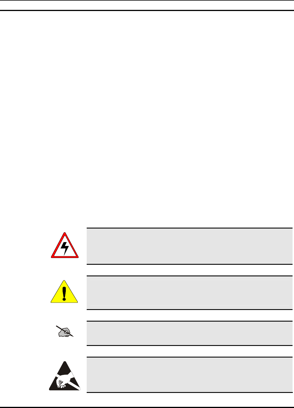
• For concrete floors, use 1/2" drop-in expanding anchors with an insulating nylon
washer under the fastener head to anchor the racks (see Figure 3-1: Bolt
Assembly Hardware and Figure 3-2: Nylon Washer and Bolt Assembly).
1. Drill pilot holes for the anchors using the appropriate-sized carbide-tipped
drill bit. The pilot holes must not exceed 1-1/2" in depth.
2. Insert the anchors into the pilot holes.
3. Place insulating phenolic strip(s)2 and under the cabinets/racks before bolting
them in place.
4. Place the cabinet/rack over the holes.
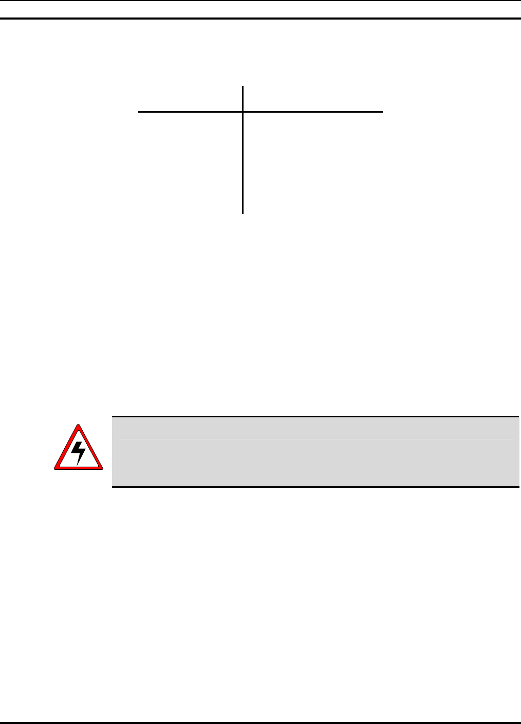
5. Assembly the bolts, fender washers and nylon washers.
6. Insert the bolt and washer assemblies into the pilot holes.
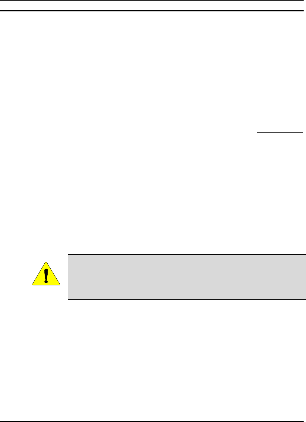
7. Tighten the bolts until firmly set (see Figure 3-3: Concrete Floor Mounting
and Figure 3-4: Bolt Assembly Used to Bolt Rack to Concrete Floor).
CAUTION
Be careful not to over tighten bolts to avoid breaking the phenolic bushings.
2 Phenolic strips are only required if the floor is pure concrete. Concrete floors covered with linoleum do not require phenolic
strips.
MM102225V1, Rev. B
20
Figure 3-1: Bolt Assembly Hardware
Top View
Side View Bottom View
Bolt Assembly
Figure 3-2: Nylon Washer and Bolt Assembly
NYLON WASHER
CONCRETE FLOORING
BOTTOM OF CABINET
FENDER WASHER
EXPANDABLE
CONCRETE ANCHOR
BOLT
PHENOLIC STRIP
Figure 3-3: Concrete Floor Mounting
LEAD ANCHOR
NYLON WASHER FENDER WASHER
BOLT
MM102225V1, Rev. B
21
Figure 3-4: Bolt Assembly Used to Bolt Rack to Concrete Floor
• For wood floors, use a lag bolt with an insulating nylon washer under the head to
bolt the racks to the floor. Insulating phenolic strips under the racks are not
required. No pilot hole is needed on wood floors.
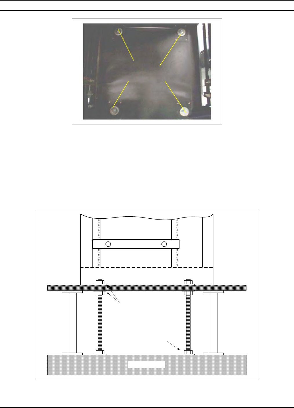
• For raised floors, the rack attachment procedure is quite different. The first and
last racks in the row are bolted to the sub-floor as shown below. The remaining
racks are bolted to the end racks, to each other, or both. Insulating phenolic strips
must be placed under each rack (see Figure 3-5: Raised Floor Rack
Attachment).
Concrete Subfloor
Concrete Anchor
Rack Cutaway
Nylon Washers
Figure 3-5: Raised Floor Rack Attachment
BOLT
ASSEMBLIES

MM102225V1, Rev. B
22
3.4 CABLING EQUIPMENT RACK COMPONENTS
Once the racks have been installed, interrack cable connections must be made, and racks
must be connected to a power source and grounded, as well as connected to external
communications sub-systems such as antennas. Follow this procedure in accordance with
M/A-COM, Inc. Quality Standards Manual GQM0221. Possible rack-ups of equipment
cabinets are shown in Figures 6 and 7.
44 RU available
Rack total height is 83" of
which 77" is usable.
Rack Depth is 24"
Rack Width is 22"
Notes:
Need cable lacing
guides in rack
Need grounding for all
rack equipment
DCX #7 through #10
are currently not
required
BLANK
10 RU---
20 RU---
30 RU---
40 RU---
44 RU---
0 RU---
2 RU
1 RU
2 RU
BLANK
ION OR DPS ALARM MODULE
RACK BREAKER PANEL
2 RU
3 RU
3 RU
BLANK (required)
SITE ACCESS SERVER2 RU
1 RU
BACKUP DCX
ISM RADIO INTERFACE
3 RU
RACK LABEL
1 RU
RX SPLITTER
2 RU
2 RU
2 RU
2 RU
2 RU
2 RU
2 RU
2 RU
2 RU
2 RU
5 RU---
25 RU---
15 RU---
35 RU---
BLANK2 RU
BLANK OR DCX #3
DCX #1
BLANK OR DCX #4
BLANK OR DCX #5
BLANK OR DCX #2
BLANK OR DCX #6
BLANK OR DCX #7
BLANK OR DCX #8
BLANK OR DCX #9
BLANK OR DCX#10
BLANK
2 RU
A Digital Controller/
XTransceiver (DCX)
contains two cards: a
Base Station
Controller (BSC) and
a Base Station
Transceiver (BSX)
Figure 3-6: Possible Rack-Up of Tower Site Rack #1
For One To Ten Base Stations Plus Backup And ISM Radio Options
MM102225V1, Rev. B
23
Notes:
Need cable lacing
guides in rack
Need grounding for all
rack equipment
44 RU available
Rack total height is 83" of
which 77" is usable.
Rack Depth is 24"
Rack Width is 22"
10 RU---
20 RU---
30 RU---
40 RU---
44 RU---
0 RU---
TT AMP CONTROLLER
RACK BREAKER PANEL
3 RU
RX AMPLIFIER2 RU
RACK LABEL
1 RU
35 RU---
25 RU---
15 RU---
5 RU---
3 RU
BACKUP HPA
DUPLEXER AND POWER SENSOR
4 RU
3 RU
HPA #2
HPA #4
HPA #3
HPA #1
4 RU
4 RU
4 RU
4 RU
TX COMBINER
6 5 4 3 2 1
10 RU
2 RU BLANK
Figure 3-7: Possible Rack-Up of Tower Site Rack #2
With Separate TX/RX Antenna Option For Base Stations #1 To #4 Of Six Maximum Plus Backup Option
CAUTION
Use the right tool for the job!
Eight Inch-Pound Torque Wrench or Newton/Meter Wrench for SMA-Type
connectors
Soft Jaw Connector Pliers for N-Type connectors
3.4.1 Interrack Cable Connections
1. On the back of each High-Power Amplifier (HPA) is an RF cable attached to the RF
Input port. Attach each of these cables to the RF Output port on the companion
Digital Controller/(X)Transceiver3 (DCX) (see Figure 3-8: HPA RF Input
Connection and Figure 3-9: DCX RF Output Connection).
3 Digital Controller/(X) Transceiver (DCX) contains two cards: a Base Station Controller (BSC) and as Base Station
(X)Transceiver (BSX).
MM102225V1, Rev. B
24
Figure 3-8: HPA RF Input Connection
Figure 3-9: DCX RF Output Connection
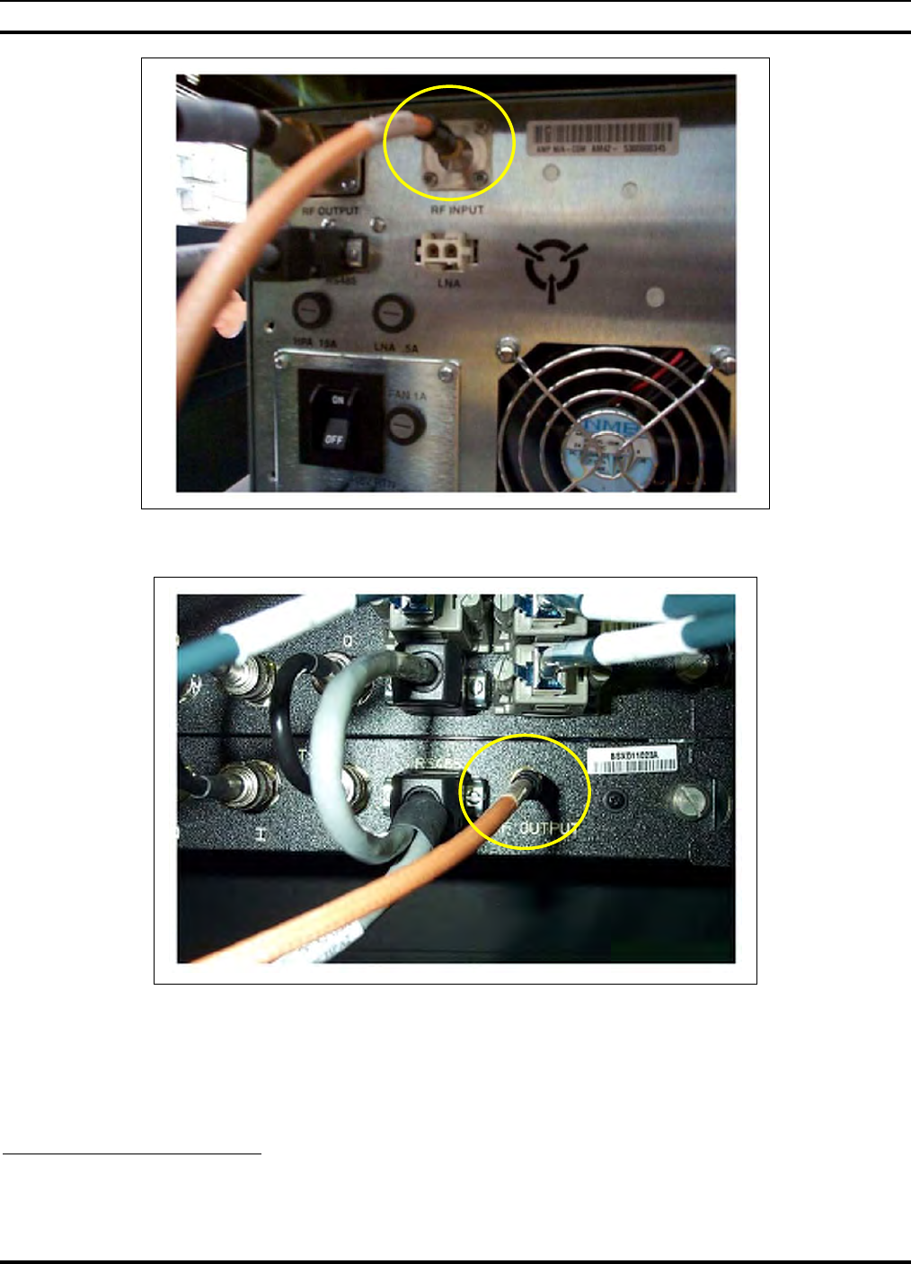
2. Racks that hold the HPA's have two large unconnected wire bundles covered with a
split loom. Pull these bundles to the adjacent rack, which contains the DCXs and the
Base Station Alarm Module4 (see Figure 3-10: Wire Bundles with DCX and Base
Station Alarm Wiring).
4 The Base Station Alarm Module can be an ION Alarm manufactured by Sentinel or a NetGuardian Alarm, model D-PK-
NETGD-12053 manufactured by DPS Telecom.
MM102225V1, Rev. B
25
Figure 3-10: Wire Bundles with DCX and Base Station Alarm Wiring
(This figure is for the ION Alarm only. The DPS Alarm uses punchblock connections.)
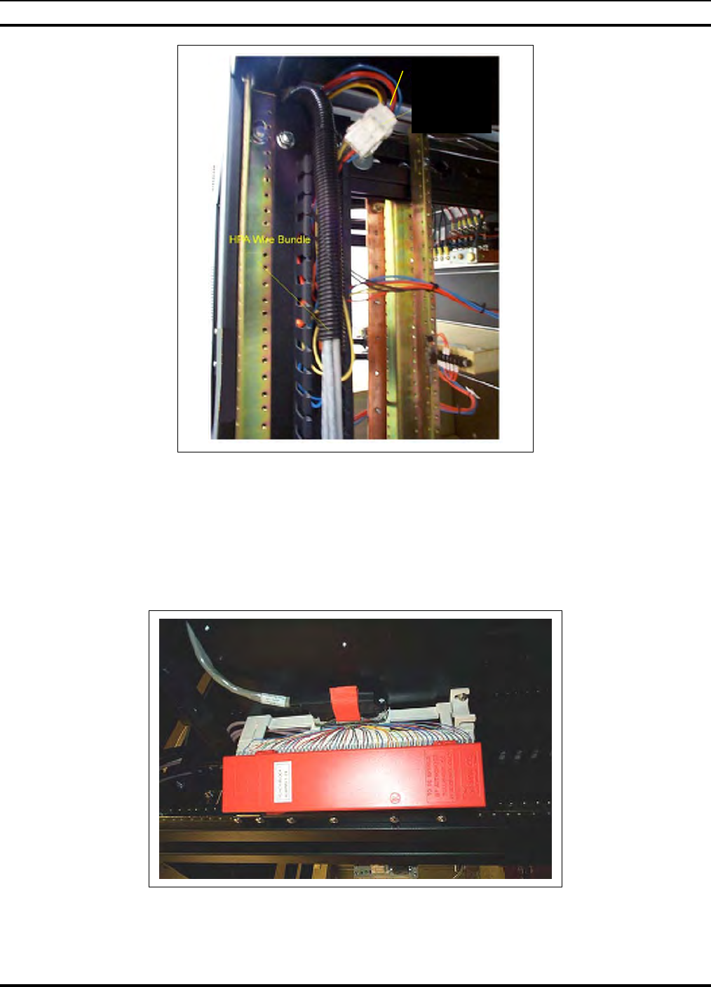
3. Included in the wire bundle above, is a wiring harness with the female half of a
MATE-N-LOK® connector. Locate the male half (it connects to the harness that runs
to the Contact Closure Inputs plug on the Base Station Alarm Module) and connect
the MATE-N-LOK connectors (see Figure 3-11: DPS Alarm Punchblock
Connector).
Figure 3-11: DPS Alarm Punchblock Connector
ION Alarm
Bundle with
Lock-n-Mate
Connectors
MM102225V1, Rev. B
26
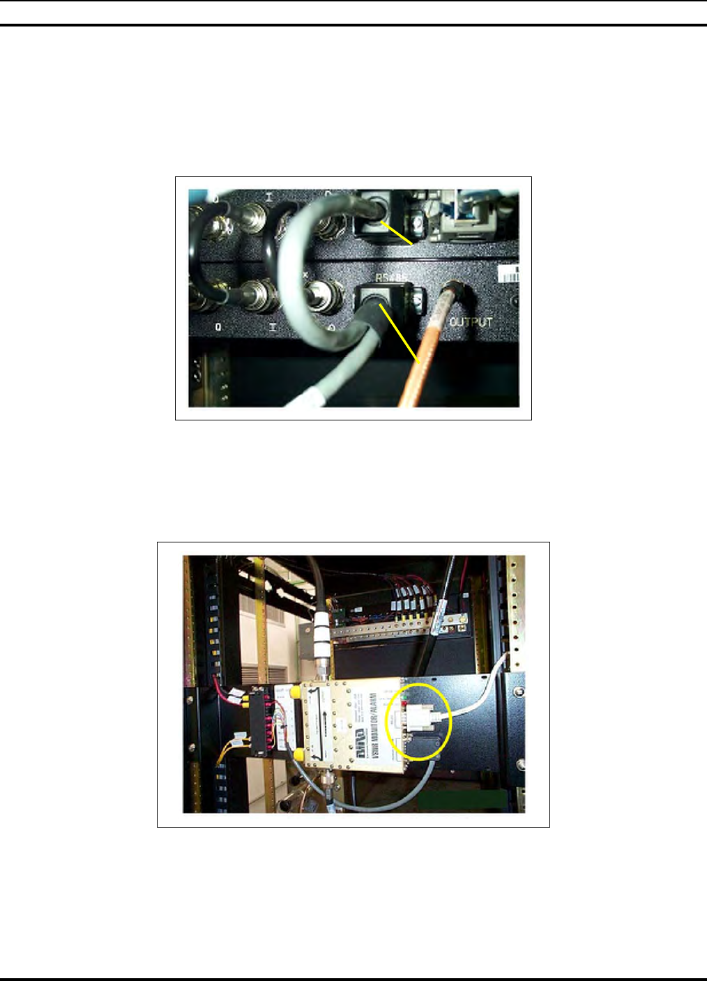
4. The remaining cables in this wiring bundle are data cables that attach to each DCX.
Dress these cables into the cable tray. Each data cable terminates in a pigtail with an
RS-485 connector on both the main cable and its pigtail. Following the labels on each
data cable, plug the main cable and its pigtail into the two RS-485 ports on each
DCX. The main cable plugs into the bottom (RF) half of the DCX (BSX) and the
pigtail plugs into the top (digital) half of the DCX (BSC) (see Figure 3-12: RS-485
Main Cable and Pigtail Plug Connected to DCX).
Figure 3-12: RS-485 Main Cable and Pigtail Plug Connected to DCX
5. Locate the cable attached to one of the host ports on the Alarm Module that has an
RS-232 connector on the free end. Plug this connector into the RS-232 port on the
Bird Electronic Corporation Power Monitor (VSWR) in the adjacent rack (see Figure
3-13: RS-232 Connector from Alarm Module to Bird Power Monitor (VSWR).
Figure 3-13: RS-232 Connector from Alarm Module to Bird Power Monitor (VSWR)
6. For Sites with a dual antenna, locate the Tower-Top Amplifier Control Box. In the
adjacent rack, locate the cable attached to the Input port of the TX/RX multi-coupler.
Connect the free end of that cable to the Tower-Top Amplifier Controller's Receiver
Pigtail Plug
Main Cable
MM102225V1, Rev. B
27
Multi-Coupler port (see Figure 3-14: Cable Connecting the Tower-Top Amplifier
Control Box to the Input port of the Multi-Coupler).
Figure 3-14: Cable Connecting the Tower-Top Amplifier Control Box to the Input port of the Multi-
Coupler
3.4.2 Connecting Power Source and External Equipment
Once rack-to-rack cables have been connected, the racked equipment in the enclosure
must be connected to external equipment and to the power source. For a layout of the
cable tray refer to Figure 3-15: Cable Tray Layout.
AC Conduit
RF Cables
Ground Wires
Control / Data Cables
DC Power Cables
*
* May not be present for -48VDC Sites.
Figure 3-15: Cable Tray Layout
MM102225V1, Rev. B
28
3.4.3 Connect Cabling for the Power Source
1. Run two DC power cables (#6 insulated red connected to -48 volts) and ground (DC
return insulated black) from the site's -48VDC Distribution Panel (see Figure 3-17: -
48 Volt Breaker Distribution Panel of the DC Power Supply - Red Wire5 and Figure
3-18: DC Return Distribution Bar - Black Wires) to each rack, attaching the cables
to the racks.
Figure 3-16: DC Power Connection Found in Each Rack - Black (DC Return) and Red (-48 Volt) wires
Figure 3-17: -48 Volt Breaker Distribution Panel of the DC Power Supply - Red Wire
5 The DC supply may not be the make shown here.
Red
–48VDC
Black
Return
MM102225V1, Rev. B
29
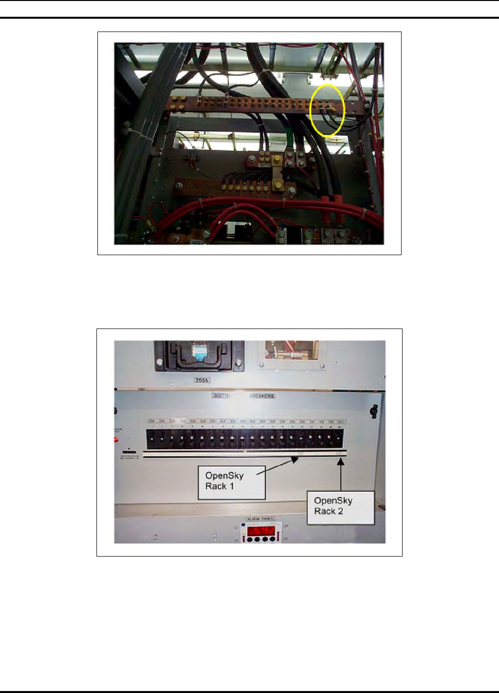
Figure 3-18: DC Return Distribution Bar - Black Wires
2. If not already labeled, label OpenSky circuits in the breaker panel to identify each
rack (see Figure 3-19: Properly Labeled OpenSky Circuit Breakers in the
Distribution Panel - OpenSky Rack 1, OpenSky Rack 2, etc.)
Figure 3-19: Properly Labeled OpenSky Circuit Breakers in the Distribution Panel
3. Route cables as specified by the installation procedure, using existing cable trays and
overhead ladders, routing cables under raised floors, and so on.
4. Route DC power cables together and maintain at least two inches (2") spacing
between the DC power cable bundle and other types of cables.
MM102225V1, Rev. B
30
3.4.4 Connect Grounding Cables to Equipment Racks
Attach a ground cable to each rack.
1. Run #6 Green grounding cable (stranded copper) from each rack ground directly to
the single-point ground bar in each enclosure.
CAUTION
All bends in the grounding cables must be < 70-degrees.
All bends in the grounding cables must have minimum bend radius of 8 inches.
See the M/A-COM Quality Standards Manual (GQM0221) for more information.
2. At a single point cabinet ground, use a two-hole lug to attach the ground cable. Route
the cables as specified by the installation procedure, using existing cable trays and
overhead ladders, routing cables under raised floors, and so on (see Figure 3-20:
Single Point Ground That is Found on Each Rack and Figure 3-21: Ground Bar).
Figure 3-20: Single Point Ground That is Found on Each Rack
Figure 3-21: Ground Bar
MM102225V1, Rev. B
31
3. Route the ground cables together and maintain at least two inches (2") spacing
between the ground cable bundle and other types of cables.
3.4.5 Connect Antenna Cables to Equipment Racks
Attach the antenna cables to the communications equipment.
1. Prior to the communications equipment installation, one or two antennas will have
been installed at the site. The antenna cables will have been terminated inside the
enclosure onto a metal plate (ground plane).
• For single antenna sites, the incoming antenna cable terminates in a
PolyPhaser® (surge protector) attached to the ground plane.
• For dual antenna sites, both the transmission and receiving antennas' incoming
cables terminate in a PolyPhaser (surge protector). Systems with tower-top
amplifiers require a special DC Injection/DC Path Protector (PolyPhaser
#DC50LNZ+30-MA). The 1-5/8" cable is the TX cable and the 7/8" cable is the
RX cable when used with a Tower Top Receive Amplifier.
Figure 3-22: Dual Antenna PolyPhasers (Surge Protectors)
2. Attach drop cables from the PolyPhaser to the appropriate antenna connection points
in the OpenSky equipment racks.
3. Route the cables appropriately, or as specified by the installation procedure, using
existing cable trays and overhead ladders, routing cables under raised floors, and so
on.
4. Maintain at least two inches (2") spacing between the antenna cables and other
cables.

MM102225V1, Rev. B
32
3.4.6 Connect the T1 Network
Connect the high-speed digital T1 (telephone) network Interface to the Site Access Server
as defined by the Site Deployment Order.
NOTE
In most installations, this connection goes to microwave equipment.
3.4.7 Site Clean Up
Before leaving, remove any debris, such as wire clippings, metal shavings, dust mounds,
etc. from the site.
3.5 COMPLETING THE INSTALLATION
Once the OpenSky equipment has been installed, perform field testing as detailed in
Section 4.0 SITE TEST PROCEDURES to verify operation according to specifications of
installed equipment racks with externally connected subsystems such as antennas.
Procedures:
1. Perform testing to verify correct operation and performance of the installed
equipment racks, following the procedures specified in Section 4.0 SITE TEST
PROCEDURES.
2. Set HPA transmission power level, following the procedure specified in Section
7.06.7 -TX POWER CALIBRATION (MANDATORY).
3. If problems occur during installation, describe them and detail how they were
resolved. If the installation could not be completed, describe the obstacles and clearly
explain what was done and what remains to be done.

MM102225V1, Rev. B
33
4.0 SITE TEST PROCEDURES
4.1 PURPOSE AND SCOPE
This section describes post installation tests required for compliance testing of the M/A-
COM Wireless Systems OpenSky Digital Base Station. This section defines and details
the test plan and methodology for each test.
Objective: This test confirms a base site receive channel is not corrupted by site specific
noise or interference. Site installation and site gain optimization should be completed
before this test is performed. The NIMCAS site optimization program provides an
expected difference between terminated and antenna connected quieting tests. Measured
results should be within 2 dB of this value.
This section covers tests that perform two functions:
• Verify that all contractual requirements as detailed in the system Requirements
Traceability Verification Matrix, (RTVM), are met. These tests are identified as
mandatory and are linked to the relevant section for the RTVM.
• Ensure that the site, as installed, is operating at optimum performance. These tests are
not mandatory but clearly have impact on some of those that are.
To ensure that the system is installed and configured correctly, the following procedures
must be performed. In addition, several tests are performed to validate the RF
performance of the station and to ensure compliance with the station FCC license.
This section is therefore divided into the following areas:
• Verification Testing
• Equipment Configuration
• Compliance Testing
• Performance Testing
• Operational Testing
• Network Connectivity
• Final Operating Capability
• Appendices: Supplemental information on equipment configuration and control
access.
⇒ Base Site Configuration Procedure should also be consulted for configuration
questions (see APPENDIX F - TYPICAL BASE STATION
CONFIGURATION).
⇒ Installed Site Cavity Tuning Procedure should also be consulted for Filter Tuning
(see APPENDIX H - VERIFICATION TESTING – TRANSMIT FILTER
TUNING).

MM102225V1, Rev. B
34
4.2 OVERVIEW OF OPENSKY BASE SITE EQUIPMENT
An OpenSky base station consists of a variety of products and includes radio transmitting
and receiving equipment, RF distribution equipment and network communications
system interface equipment.
OpenSky is a digital system and has some significant differences in terms of fixed
network connectivity to that commonly seen with conventional analog systems. In
particular, base station controllers (BSCs) communicate via an access server and are
connected back to a central office or dispatch center via digital circuits.
OpenSky base station equipment is available in five primary RF configurations. This
document covers Types 1, 2, 3, and 4 listed below. Type 5 is covered separately.
1. Primary site with separate transmit and receive antennas: Referred to as a Tower Top
Site.
2. Primary site with a single antenna for transmit and receive: Referred to as a Duplexed
Site.
3. Outdoor Enclosure with separate transmit and receive antenna.
4. Outdoor Enclosure with a single antenna for transmit and receive.
5. Low profile site providing coverage fill: Referred to as a Cell Site.
4.3 TEST METHODOLOGY
Equipment configuration and testing must be performed in accordance with the
instruction given in this document. Tests must also be conducted in the order given in this
document as adjustments made during certain procedures may affect the results of other
tests.
Testing an installed base site comprises performing standard forward and reverse channel
tests to ensure correct operation of the entire installation. Testing also verifies physical
and application layer connectivity to the Regional Operations Center serving the site
under test via a communications link.
Required specifications are verified using one of the following methods:
1. Inspection: An observation or examination of an item against the applicable
documentation to confirm compliance with the requirements.
2. Analysis: Interpretation, interpolation, or extrapolation of analytical or empirical data
under defined conditions of reasoning to show theoretical compliance with stated
requirements.
3. Demonstration: Verification of an operational or functional capability by one or
more performances before qualified witnesses, as designated by the customer.
Instrumentation or data recording beyond that provided indigenously by the elements
to be verified shall generally not be required.
4. Objective Test: Performance of a functional operation under specific conditions
involving the use of instrumentation, special test software, and/or special test
equipment to generate, acquire, and/or record data. This method may include an
analysis of test data.
MM102225V1, Rev. B
35
4.4 PREPARATION
To prepare for the start of testing, it is important that all test equipment be powered up
now and allowed to thermally stabilize. Begin by powering up the Communications Test
Set HP 8920.
Record the specifics of each of the system components.
Before testing the complete system, verify that the system is cabled correctly. The tower-
mounted receive amplifier will not power up until it senses that the indoor control panel
has been connected via the RF feed cable and the multi-conductor control cable. The
initial sections of this procedure describe how to check for correct installation,
particularly those areas that were disturbed as part of the shipping process.
4.5 RECORDING TEST RESULTS
The main body of this document provides space for the recording of all test results and
equipment configuration parameters. These must be supplemented where indicated by
equipment configuration hardcopy printouts taken for each RF channel being tested.
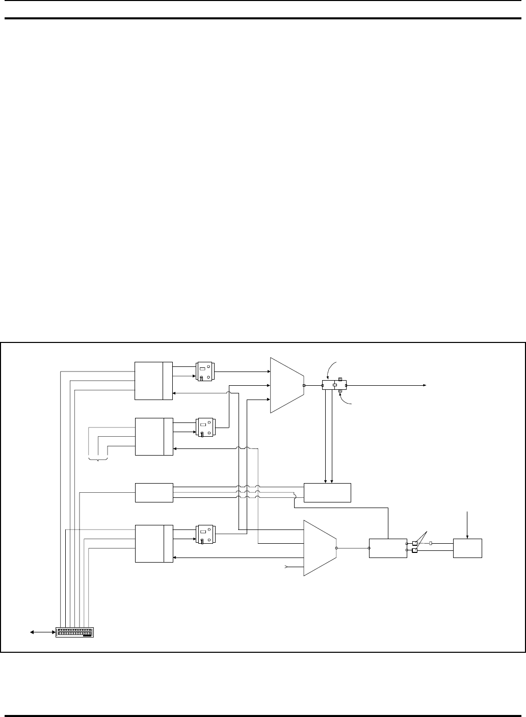
4.6 BASE SITE BLOCK DIAGRAM
Figure 4-1: 3-Channel Base Station with Tower Top Amplifier Block Diagram, shows
the Block Diagram for a three-channel site installation.
Rx
Splitter
(4 CH)
network38.4 kbps
Site Access Server
(SAS)
inter-BSC Transmitter
Combiner
(3 CH)
terminal
Alarm Module
Alarm
Cables
VSWR Monitor
Feeder
High Power Amp 3
Base
Station
Controller
X
C
V
R
RS485
High Power Amp 1
Base
Station
Controller
X
C
V
R
RS485
RS232
Power Sensor
Lightning Protector
Tower-Top
LNA Controller
Feeder
Tower-Top
LNA
High Power Amp 2
Base
Station
Controller
X
C
V
R
RS485
network38.4 kbps
inter-BSC
terminal
Tower Top LNA
Power and Control
network38.4 kbps
inter-BSC
terminal
To SAS
To Tx Antenna
From RF network
for mobile radios
Rx Antenna
DCX 1
DCX 2
DCX 3
PolyPhasers
Figure 4-1: 3-Channel Base Station with Tower Top Amplifier Block Diagram
MM102225V1, Rev. B
36
4.7 INSPECTION
In this section, the location of the installation is recorded and equipment configuration
parameters are verified against the As Built. In addition, general workmanship and
quality of assembly and installation are inspected
NOTE
Only selected parameters are checked against the recorded factory configuration as all
parameters are programmed into equipment before leaving the factory and hence should
not require to be modified.
4.7.1 Pre-test Inspection
Objective: To verify that the site installation has been satisfactorily completed and that
newly installed cable interfaces have been correctly connected, especially inter-rack
cabling disconnected during shipment.
NOTE
Before commencing this section of tests, ENSURE THAT ALL RACK CIRCUIT
BREAKERS ARE IN THE OFF POSITION.
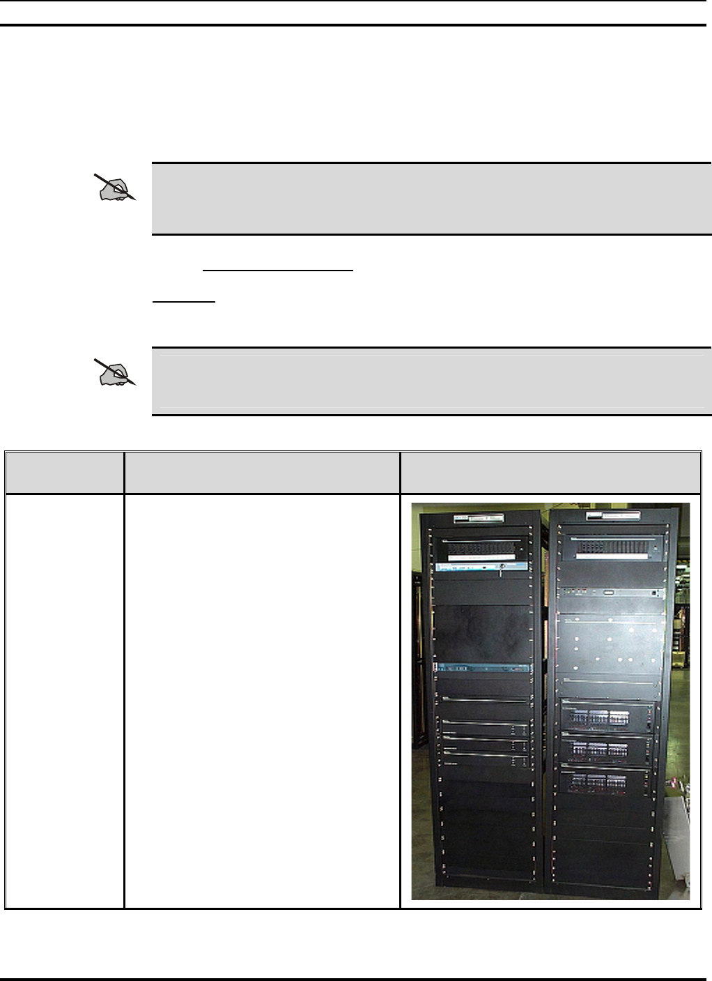
PRE-TEST
INSPECTION ACTION MISCELLANEOUS
1.
A two rack three channel base station is
as shown in the figure to the right. Rack
1 (on left) contains system transceivers,
communication interfaces and control
and monitoring equipment; Rack 2 (on
right) contains transmit path RF power
amplifiers and combining equipment.
MM102225V1, Rev. B
37
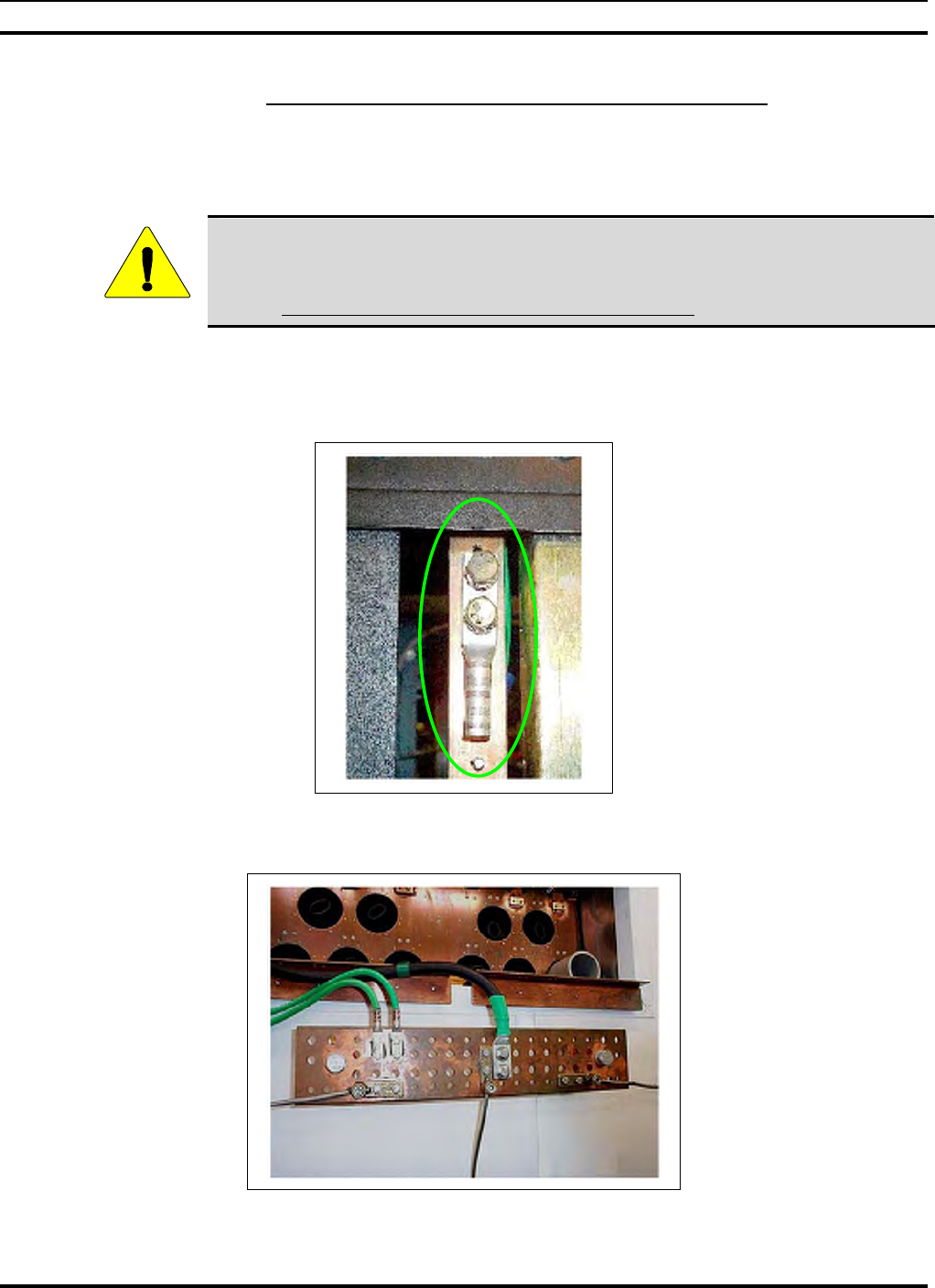
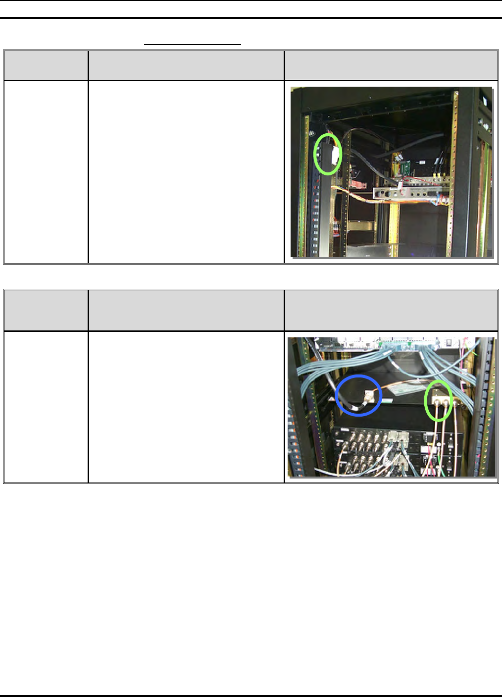
4.7.2 Interrack Cabling
ALARM
CABLING ACTION MISCELLANEOUS
2.
The photograph to the right shows the
location of the inter-rack alarm
interconnect cable.
Verify that it has been connected as
shown where the circle is located.
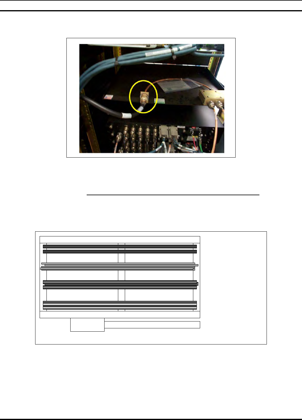
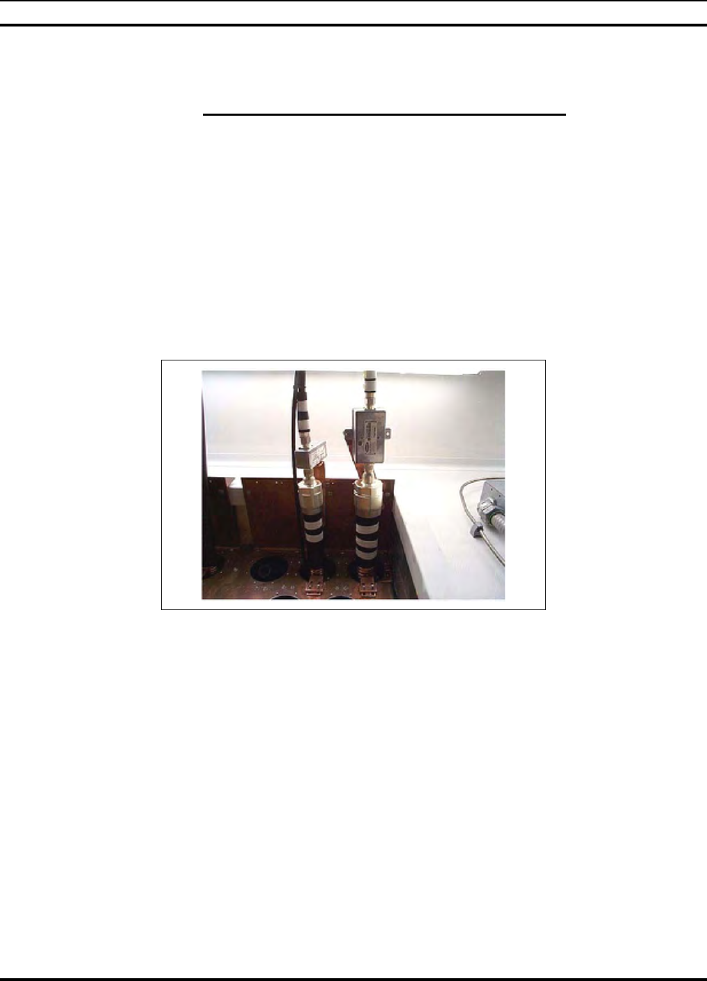
RECEIVE
MULTICOUPLER
INPUT
ACTION MISCELLANEOUS
3.
The photograph to the right shows the
source and destination points for the
receive Multicoupler feed. Verify that it
is connected as shown.
Also, verify that unused output ports are
terminated with a 50-Ohm terminator.
MM102225V1, Rev. B
38
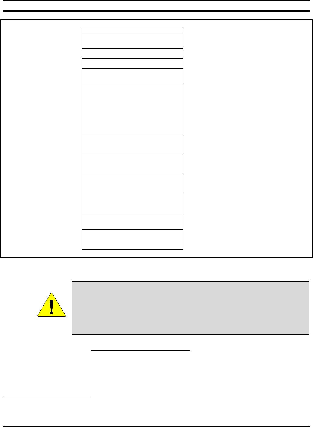
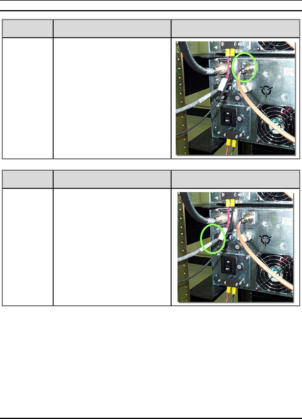
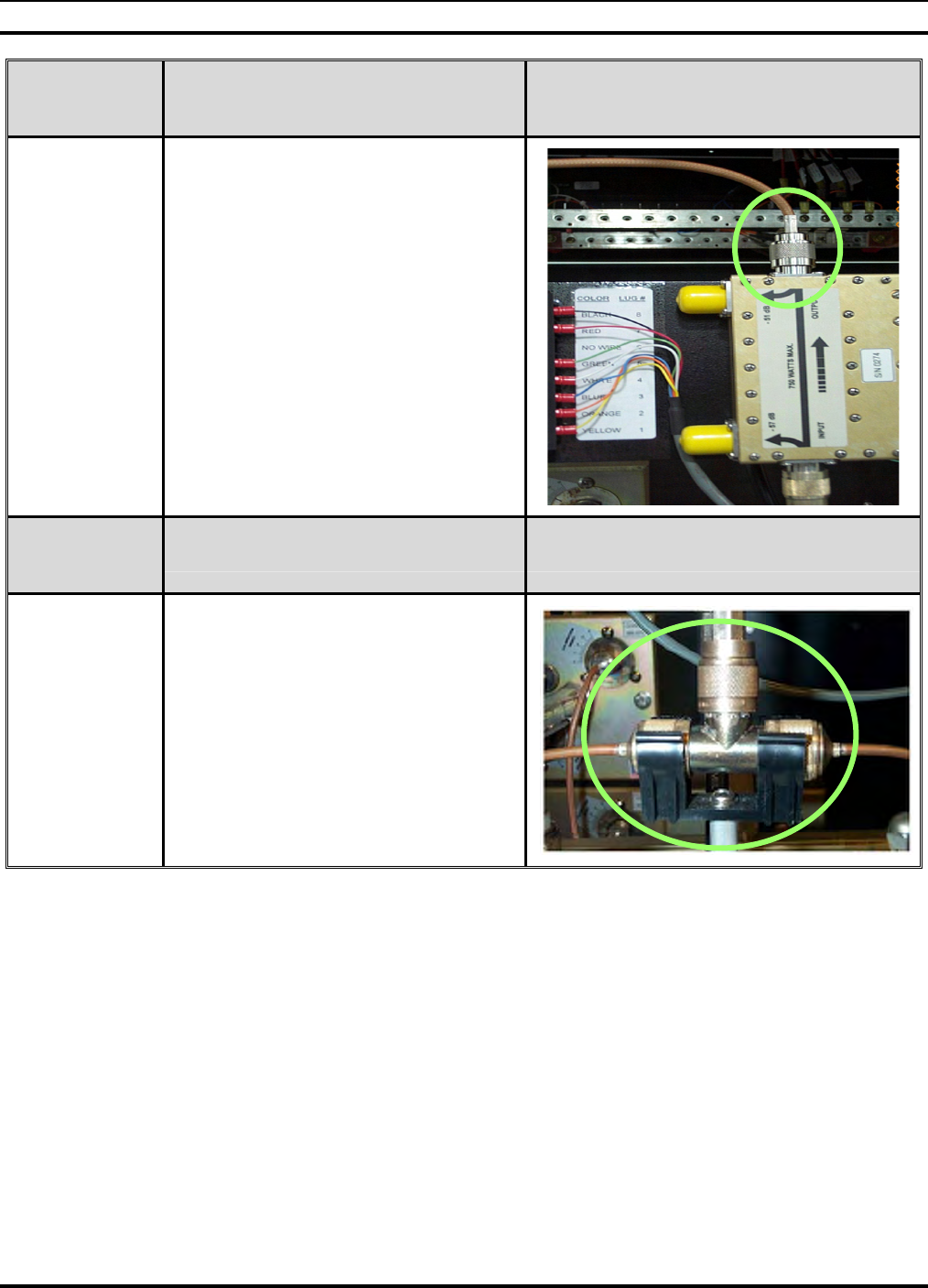
HPA RF
INPUT ACTION MISCELLANEOUS
4. The photograph to the right shows the
destination point for the HPA RF Input.
Verify that they are connected as shown.
HPA CONTROL
CONNECTION ACTION MISCELLANEOUS
5.
The photograph to the right shows the
destination point for the HPA control
cable. Verify that they are connected as
shown.
MM102225V1, Rev. B
39
4.7.3 New Cabling
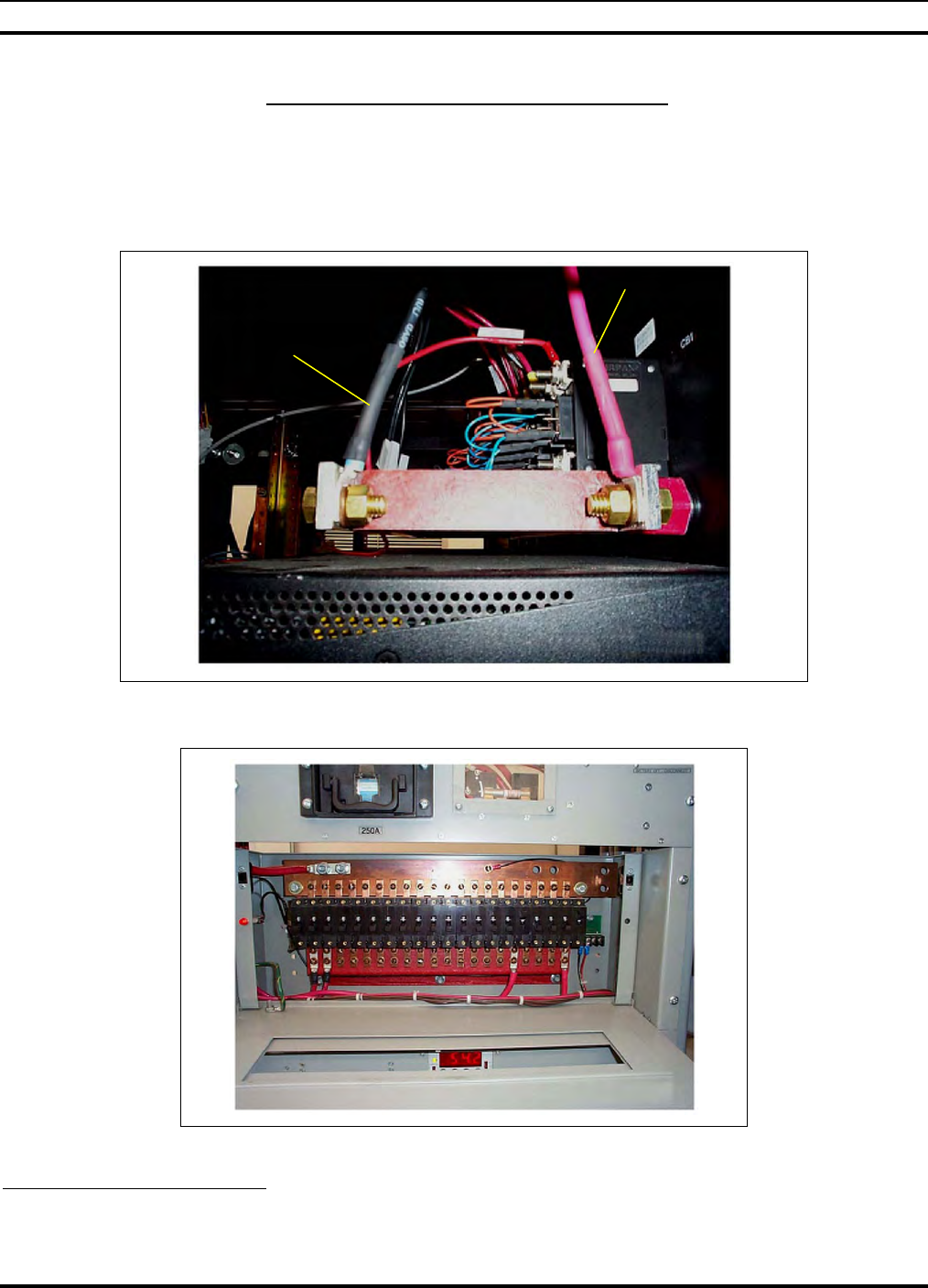
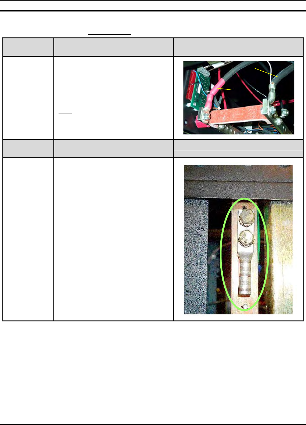
RACK POWER
CONNECTION ACTION MISCELLANEOUS
6.
The photograph to the right shows the
connection points and polarity of the DC
power connection to each power
distribution panel. Verify that they are
connected as shown.
Note: The red cable is the most
negative, i.e. -48VDC. The black cable is
the return.
RACK
GROUNDING ACTION MISCELLANEOUS
7.
The photograph to the right shows the
connection point for rack to halo
grounding. The halo is located inside the
shelter and is part of the shelter
grounding system that is fed to an earth
ground. Connect a black ground cable
from the halo to the two hole lug shown
here.
Red
Black
MM102225V1, Rev. B
40
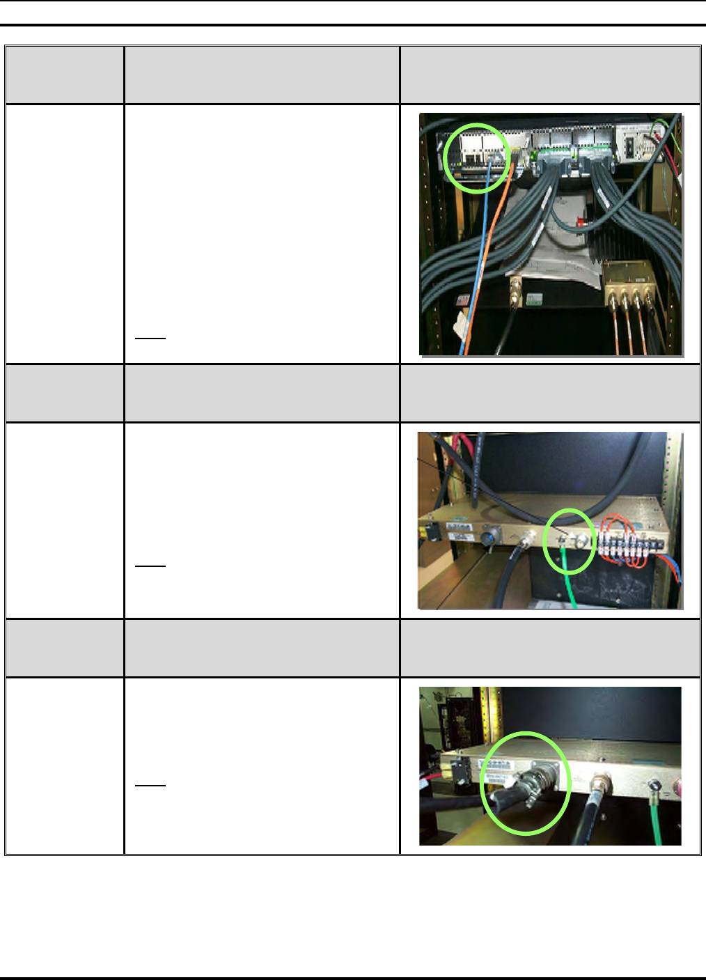
SYSTEM
COMMUNI-
CATIONS
ACTION MISCELLANEOUS
8.
The photograph to the right shows the
in-rack connection point for T1
communications.
The destination of this connection will
vary by site; however, verify that a
modular style plug wired (T568B) is
used to connect the site communications
interface with the base site T1.
If equipped with ISM Backhaul, the
Orange cable is the 10BaseT connection
to the ISM Backhaul Router.
Note: Actual cables may be different
colors.
RECEIVE
ANTENNA
CONNECTION
ACTION MISCELLANEOUS
9.
The photograph to the right shows the
in-rack connection point for the system
receive antenna. Verify that the jumper
cable to the receive antenna is present
and disconnect it from the receive input.
Note: This is only for Tower Top
Amplifier sites.
TTA
CONTROL
CABLE
ACTION MISCELLANEOUS
10.
Ensure that the 5-conductor Tower Top
Amplifier control cable is connected as
shown in the photo to the right.
Note: The connector is installed in the
field. To solder the connector to the
cable, refer to APPENDIX A.
MM102225V1, Rev. B
41
TRANSMIT
ANTENNA
CONNECTION ACTION MISCELLANEOUS
11.
The photograph to the right shows the
in-rack connection point for the system
transmit antenna. Verify that the jumper
cable is present and disconnect it from
the Bird Power Monitor output.
DUPLEX
ANTENNA
CONNECTION ACTION MISCELLANEOUS
12.
The photograph to the right shows the
in-rack connection point for a duplexed
system. Verify that the jumper cable is
present and disconnect it from the "T"
shaped connection.

MM102225V1, Rev. B
42
5.0 EQUIPMENT CONFIGURATION
The objective of this procedure is to verify that base station equipment has been correctly
programmed for the site at which it is installed. Testing involves connecting a laptop
computer to each piece of equipment and interrogating and recording configuration files.
A record of the configuration files will be shipped with the radio rack. Compare the
pertinent parameters with the highlighted parameters as indicated on the final
configuration documents from staging.
Required Test Equipment:
• Laptop with Floppy Disk Drive
• PC operating system and HyperTerminal
• Blank floppy disk
• Cisco® "Black Connection Cable"
• Cisco 9-pin "D" shell to RJ-45 adapter
• Or, 9-Pin Male to 9-Pin Female w/Null Adapter

MM102225V1, Rev. B
43
6.0 PERFORMANCE TESTING6
This series of tests characterizes the receive performance of the Base Station in terms of
its absolute sensitivity and its sensitivity relative to the local noise floor at the installed
site.
The base station is capable of providing a raw discriminated output to support analog
receive testing. The output is provided on the "Q" Transmitter output of the BSC when
the base station is in output mode 0.
Required Test Equipment:
• PC running suitable console application
• Cisco “Black” cable
• Cisco RJ-45 to DB9 (F) adapter
• Or, 9-Pin Male to 9-Pin Female w/null adaptor
• HP 8920 Communications Analyzer
• 30dB Directional Coupler
• Parallel Printer & Cable
6.1 ANALOG RECEIVE TESTS (MANDATORY)
6.1.1 12dB SINAD Receiver Sensitivity
Objective: The 12dB SINAD test measures the effective receive sensitivity and signal to
noise ratio of the RF Channel. This test is performed at the RF input connection, on the
BSX. Compare the results with the staging area data.
STEPS ACTION MISCELLANEOUS
1.
Connect the PC to the Terminal port of
the DCX of the base station under test.
Note: Requires Black Cisco cable &
adapter and a communications data
rate of 19,200 bps.
2. Ensure that the Disable/Enable
switches on all HPA’s are
DISABLED.
6 Taken from M/A-COM, Inc - Drawing No. GTP-0296, Rev. A
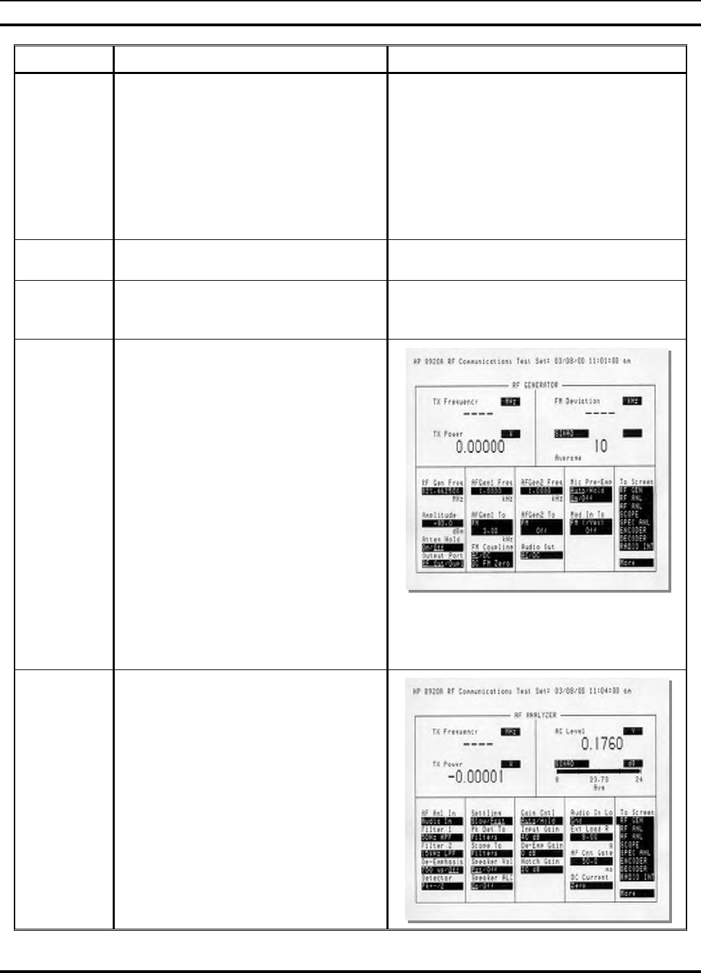
MM102225V1, Rev. B
44
STEPS ACTION MISCELLANEOUS
3.
To place the DCX in Analog Mode,
enter the sequence of commands
indicated by bold script in the example
seen to the right.
Offline [CR]
;<Various status messages>
at@outmode0 [CR]
OK
save_config [CR]
OK
Reboot [CR]
; < The Base Station Reboots>
4. Repeat Steps 1 and 2 for all other
DCX units.
5. Ensure that the DCX and HPA under
test are powered up and the HPA is
offline.
6.
On the HP 8920, select the RF GEN
screen and set the following
configuration, (see adjacent photo):
RF Gen Freq: Set for the receive
frequency of the RF path under test
(45MHz below the Transmit
Frequency) .
Amplitude: -80 dBm
Output Port: RF Out
AFGen1 Freq: 1kHz
AFGen1 To: FM 3kHz
AFGen2 To: Off
AC Level: Set to dBm plus 10
sample averaging
SINAD dB: Set for an averaging
value of 10 samples
7.
Select the AFANL screen and set the
following configuration:
AF Anl In: Audio In
Filter 1: 300Hz HPF
Filter 2: 3kHz LPF
De-Emphasis: 750 µsec
Detector: rms
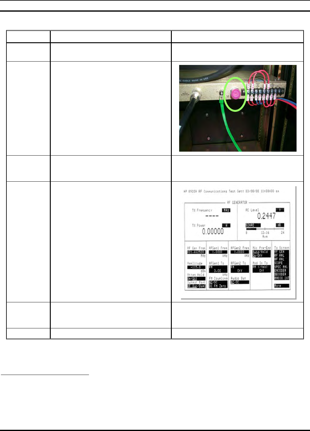
MM102225V1, Rev. B
45
STEPS ACTION MISCELLANEOUS
8. Select the RF GEN screen and place
the cursor on the Amplitude field.
9.
Configure test as follows:
• Verify HP 8920 RF IN/OUT
port is connected to the antenna
port of the TTA Controller.
• Disconnect the TX Q cable from
the DCX under test.
• Connect a Test Cable between
the TX Q port under test and the
Audio In Hi port of the HP
8920.
10. Adjust the volume control on the HP
8920 until the 1kHz test tone is
audible.
11.
On the RF GENERATOR screen,
reduce the Amplitude of the generated
signal until the indicated value for
SINAD stabilizes at a nominal value
of 12dB.
12. Record the amplitude on worksheet
and record the results on the data
sheet7.
-122 dBm
13. Repeat for all other DCX’s.
7 Refer to APPENDIX L - RECORDED DATA SHEET.

MM102225V1, Rev. B
46
6.2 ANALOG PERFORMANCE TESTING OF TOWER TOP
AMPLIFIERS
This single channel measurement is performed using external antenna coupling between
the transmit and receive antennas to deliver a test signal to the TTA. A SINAD System
level test is performed with the TTA "On" and "Off" to measure the receive system
improvement provided by the TTA. This is a relative measurement the difference
between the "On" and "Off" measured value represents the system improvement provided
by the TTA. Log the results on the site Test Data Form.
Required Test Equipment:
• PC running suitable console application
• Cisco “Black” cable
• Cisco RJ45 to DB9 (F) adapter
• HP 8920 Communications Analyzer
• 30 dB Coupler
6.2.1 Tower Top Amplifier Performance Test
Objective: The 12dB SINAD test is performed to give a relative indication of the
receive system improvement provided by the TTA by measuring the effective receive
sensitivity and signal noise ratio of any assigned site receive channel.
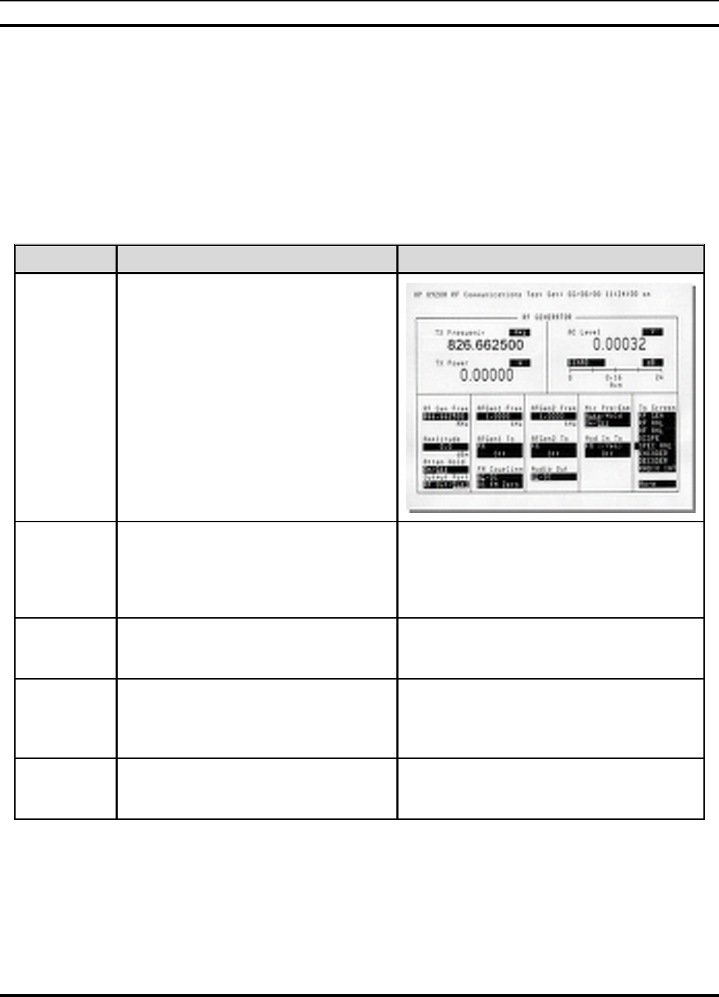
MM102225V1, Rev. B
47
6.3 TOWER TOP LOW NOISE AMPLIFIER (TTA) GAIN
MEASUREMENT (REQUIRED)
The purpose of this test is to measure the gain of the TTA. The method will be to inject a
test signal into the transmit jumper cable using a receive channel frequency. This signal
will be coupled from the transmit antenna to the receive antenna and a reference power
level measurement will be made with the TTA “On” and a second measurement will be
made with the TTA “Off”. This is a relative measurement and the difference will be the
TTA gain value.
STEPS ACTION MISCELLANEOUS
1.
Select the RF GEN screen and configure
the following:
RF Gen Freq: Set as appropriate for
any assigned receive
frequency per SDO
(TX Freq –45 MHz).
Amplitude: 0dBm
Output Port: Dupl
AF Gen 1 & 2: Off
2.
Verify a test cable is still connected from
the transmit jumper cable (normally
connected to the Bird Power Monitor
output port) and the Duplex out port on
the HP 8920.
3. Disconnect the Jumper at the TTA
Control Panel RF output labeled “ TO
RECEIVER MULTICOUPLER”.
4.
Connect a test cable between the TTA
Control Panel RF out port labeled “To
RECEIVER MULTICOUPLER” and the
Antenna In port of the HP 8920.
5. Verify that the Power Switch on the
front of the TTA Control Panel is in the
“On” position.
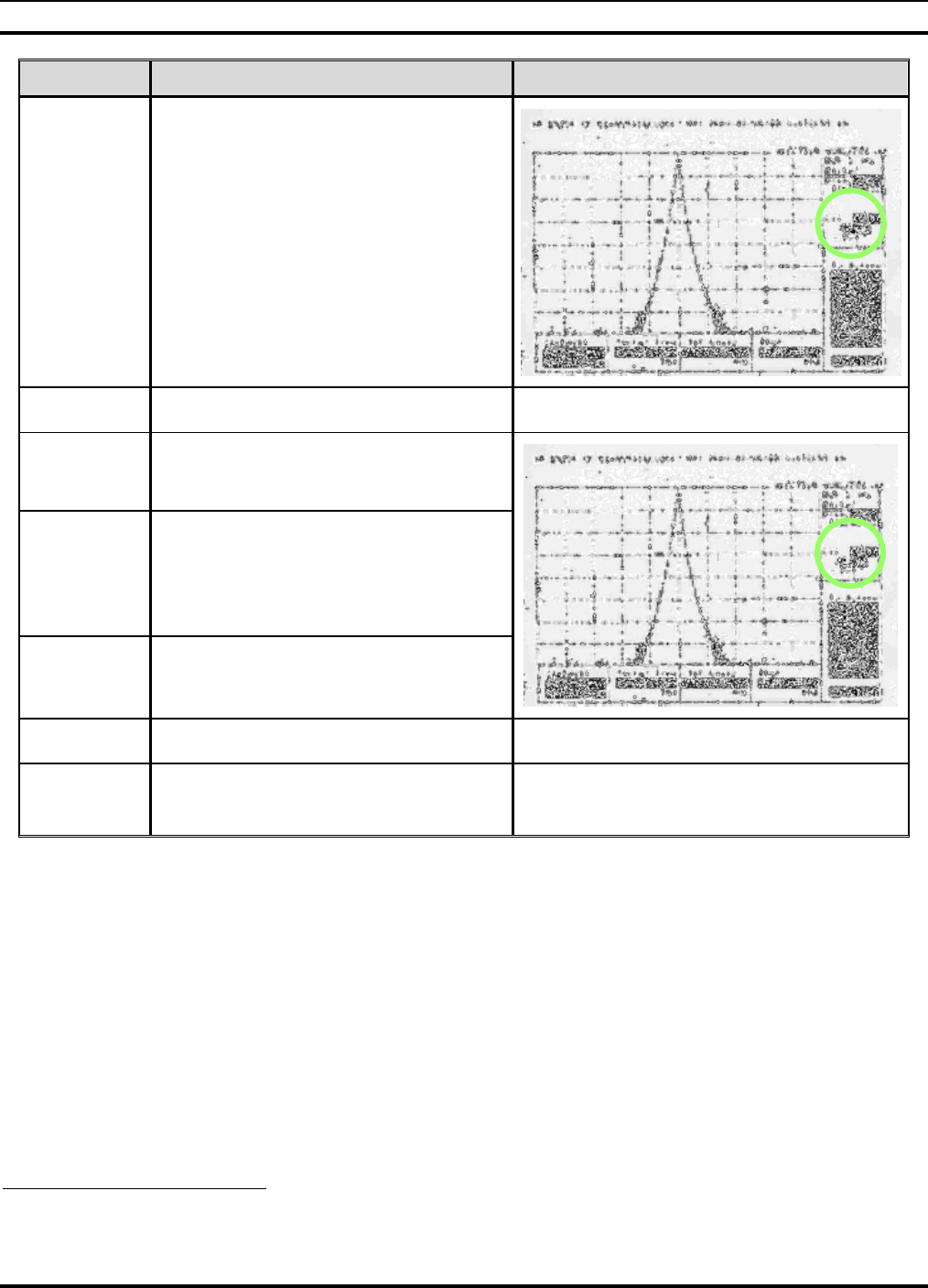
MM102225V1, Rev. B
48
STEPS ACTION MISCELLANEOUS
6.
Record the power level as indicated in
the HP 8920 Spectrum Analyzer Lvl
field. Enter this value in the TTA Gain
table, column 2 for TTA “On”8.
7. Turn the Power Switch on the front of
the TTA Control Panel to the “Off”
position.
8.
Record the power level as indicated in
the HP 8920 Spectrum Analyzer Lvl
field. Enter this value in the TTA
Amplifier Gain table, column 2 for TTA
“Off”.
9. Subtract the recorded “Off” Lvl from the
“On” Lvl.
10. Record the result (gain) in the table.
11. Reconnect the Jumper disconnected in Step 3
that goes to the TTA “To RECEIVE
MULTICOUPLER” port.
8 Refer APPENDIX L- RECORDED DATA SHEET

MM102225V1, Rev. B
49
6.4 ANTENNA 20DB QUIETING TEST (MANDATORY)
Objective: This test measures the susceptibility of the site to de-sense resulting from
site-specific interference.
STEPS ACTION MISCELLANEOUS
1.
On the HP 8920, select the RF GEN screen
and set the following configuration:
RF Gen Freq: Set for the receive
frequency of the RF path
under test. (45MHz
below the Transmit
Frequency recorded in
data collection sheet. The
set frequency will be in
the range from 806-824
MHz.
Amplitude: Off
Output Port: RF Out
AFGen1 To: Off
AFGen2 To: Off
AC Level: Set to dBm plus 10
sample averaging
2.
Select the AFANL screen and set the
following configuration:
AF Anl In: Audio In
Filter 1: 50Hz HPF
Filter 2: 15kHz LPF
De-Emphasis: Off
Detector: Pk+-/2
3. Select the RF GEN screen and place the
cursor on the Amplitude field.
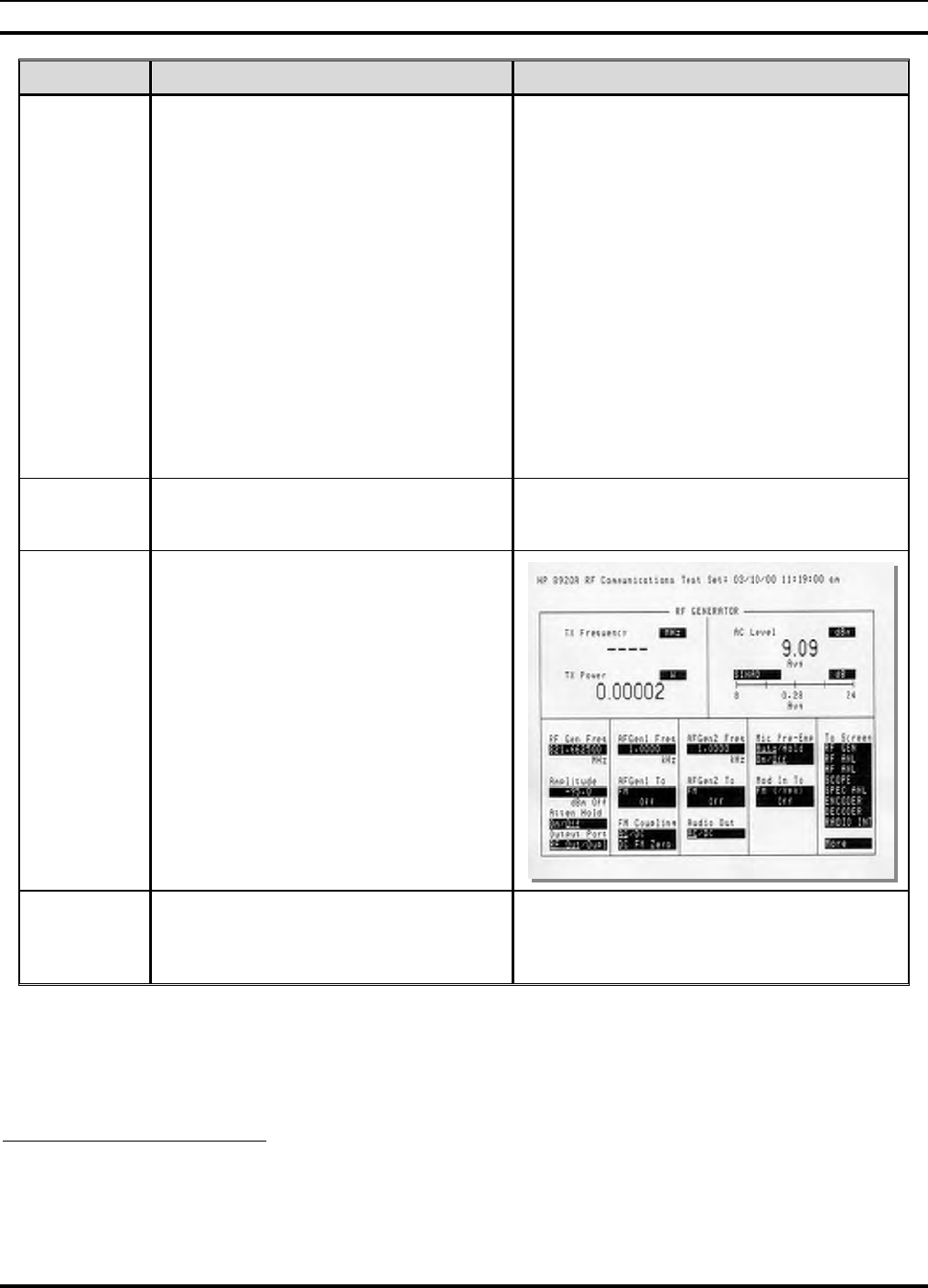
MM102225V1, Rev. B
50
STEPS ACTION MISCELLANEOUS
4.
Configure test as follows:
• Connect the 30dB Directional Coupler
to the input of the receive multicoupler.
• Connect the RF IN/OUT connector of
the HP 8920 to the coupler port labeled
as
TO ANALY.
• Connect the 50-Ohm terminator to the
ANT/TERM port of the coupler.
• Connect Duplx/SPL port to
Multicoupler Input.
• Disconnect the Tx Q cable from the
controller module of the DCX.
• Connect a Test Cable between the Tx Q
port and the Audio In Hi port of the HP
8920.
5. Adjust the volume control on the HP 8920 to
a comfortable level. White noise should be
audible.
6.
Record the measured AC Level as displayed
on the RF Generator screen and record this
on the worksheet and record the results on
the datasheet9.
7.
Enable the RF output Amplitude and raise
the signal level until the measured AC level
of demodulated channel noise decreases by
20dB.
9 Refer to APPENDIX L - RECORDED DATA SHEET
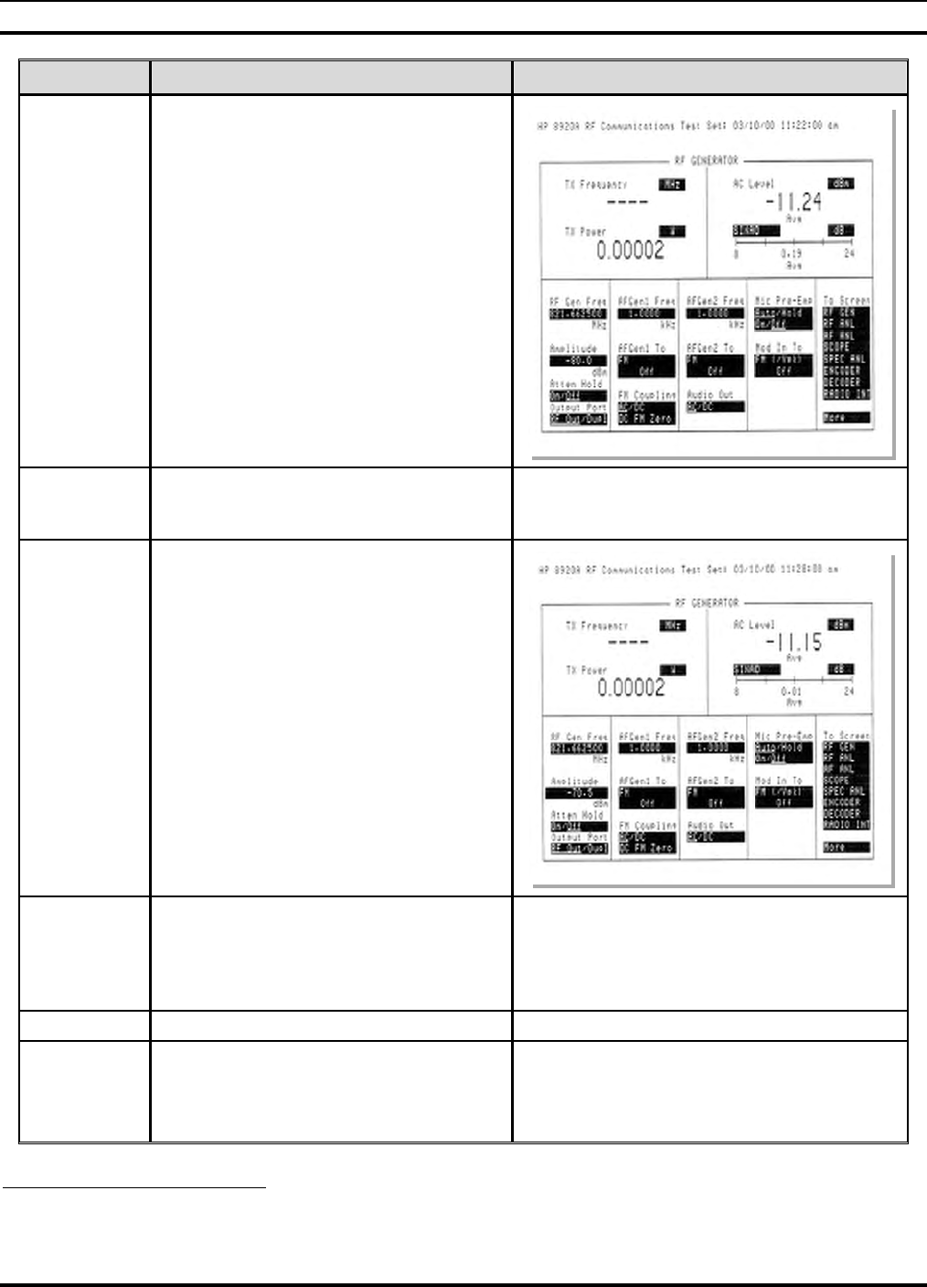
MM102225V1, Rev. B
51
STEPS ACTION MISCELLANEOUS
8. Record the new 20dB quiet value of AC
Level on worksheet together with its
associated RF input level10.
9. Replace the 50-Ohm Terminator with the
main receive antenna feed. The indicated
value of AC Level will increase.
10. Increase the RF input Amplitude to recover
the reading recorded on the worksheet.
11.
Calculate the difference between readings
obtained with Antenna versus the 50-ohm
Terminator to obtain the 20dB de-sense
value. Record this on the worksheet and
record the results on the datasheet.
12. Repeat for all other channels.
If the Site Noise on all RX Channels
exceeds 5 dB or if a single channel
exceeds 5 dB contact M/A-COM
Engineering.
10 Refer to APPENDIX L- RECORDED DATA SHEET.
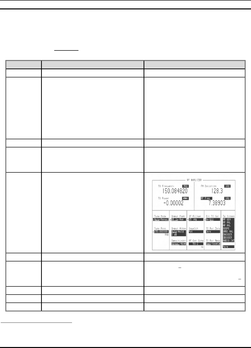
MM102225V1, Rev. B
52
6.5 BASE STATION TRANSMIT (BSX) FREQUENCY
ACCURACY TEST (MANDATORY)
Objective: The purpose of the Base Station Frequency Test is to verify that the DCX is
operating on the allocated frequency and compliant with the FCC specifications.
STEPS ACTION MISCELLANEOUS
1. Connect the PC to the DCX TERMINAL port.
2.
Using a suitable console application, enter the
sequence of commands indicated by the bold
script in the example on the right to return the
base station to digital mode.
offline
; <Various Shutdown Text is Displayed>
at@outmode1
OK
save_config
OK
reboot
; < The Base Station Reboots >
3. Repeat Steps 1 and 2 for all other DCX units.
4.
Select the RF GEN screen of the HP 8920 and
turn off the generator function by selecting the
Amplitude and pressing the ON/OFF /(YES)
key.
5.
Select the RF ANALYZER function of the HP
8920 and set the following parameters:
• Tune Mode: Auto
• Input Port: RF In
• Disconnect the I/Q cables to remove
modulation.
• Connect the HP 8920 RF/IN Port to
Bird Power Monitor TX Output Port.
6. Enable an HPA.
7. Record TX Frequency shown on Analyzer11.
TOL: Must be + 86Hz. CAUTION: Lock the
frequency counter/service monitor to a GPS
standard and then set the station frequency +
86Hz.12
8. Disable the HPA.
9. Repeat on all other DCX units.
10. Replace I/Q Cables.
11 Refer to APPENDIX L - RECORDED DATA SHEET.
12 Ensure the GPS standard is better than 0.01ppm (about 1E-8 or better).
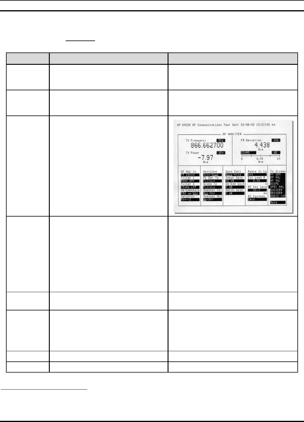
MM102225V1, Rev. B
53
6.6 TRANSMIT DEVIATION (MANDATORY)
Objective: The objective of this test is to ensure that the transmit deviation is correctly
adjusted.
STEPS ACTION MISCELLANEOUS
1. Verify that the HPA transmit Enable/
Disable switch is set to the Disable
position for all HPA’s.
2. Select the RF GEN screen and set the
Amplitude field to Off by pressing the
ON/OFF / (YES) key.
3.
Select the AF Analyzer Screen on the
HP 8920 and configure the following
parameters:
• Set AF Analyzer to “FM Demod”
• Set the Detector to “Pk+ - /2”
• Set FM Deviation to Ave 10
Samples.
4.
Set the following configuration
parameters on the RF Analyzer screen:
Tune Mode: Auto
Tune Frequency: Set for the RF path
under test.
Input Port: RF In
Sensitivity: Normal
IF Filter: 230KHz
5. Set the HPA Enable/Disable switch to
the Enable position.
6.
The measured value of FM Deviation
should be 3.0 kHz ±150 Hz for the
channel under test. Measure and record
the indicated FM Deviation on the
recorded data sheet13.
7. Disable the HPA.
8. Repeat for each RF path.
13 Refer to APPENDIX L - RECORDED DATA SHEET.

MM102225V1, Rev. B
54
6.7 TX POWER CALIBRATION (MANDATORY)
Objective: The following procedure sets the output power level at the final rack RF
transmit port based on the transmit Antenna/Feedline Gains and Losses shown in the
following examples.
STEPS ACTION MISCELLANEOUS
1.
Calculate the required HPA TX Power
setting based on the required site ERP.
HPA TX Level may be calculated as
seen on the right.
Example of Calculating and Setting an ERP
of 50dBm:
Ant Gain in dB 10dB
Feed Line Loss in dB -3dB
Net Gain 7dB
Output Power 43dBm
Net Gain +7dB
ERP 50dBm
Setup
Procedure
Verify that ALL of the HPA
disable/enable switches are in the
Disable position.
2.
Select the RF Analyzer screen
• Set the correct channel frequency
• Set the TX Power to read dBm
• Set the Input Port to “RF Input”
• Set the Input Attenuation to
“Auto” (Default)
3. Set the Sensitivity to “Normal”
(Default).
4.
Connect the Bird Power Monitor TX
Output Port to the HP 8920 RF In Port
using calibrated test cables and suitable
adapters as required.
5.
Connect the Laptop PC to the DCX
serving the HPA under test using the
black “Cisco” cable and the DB-9 to RJ-
45 Converter between the laptop “COM”
port and the DCX port.
6. Turn on the Laptop PC and launch the
Hyper Terminal.
7. With the PC connected to the DCX
serving the channel under test and
running a VT-100 Emulation.
8.
The purpose of this test is to adjust the
HPA transmit power level into the RF
transmission line to provide the site
specified ERP.

MM102225V1, Rev. B
55
STEPS ACTION MISCELLANEOUS
9.
Press the Enter key on the laptop
keyboard.
The status information on the right will
be displayed on the PC console
application. Similar to the text found on
the right.
Example: buck40:14
buck40-bs1>
Setting the
HPA TX
Power
10. Enter the command:
at@hpapowerN [CR]
Example: Where N is the desired HPA
power setting to overcome rack losses.
11. Set the HPA Disable/Enable switch to
Enable.
12. The HPA will send the message shown
on the right via the DCX to the console
display and start transmitting.
HPA> RF enabled by front panel switch.
13.
Compare the measured value TX Power
on the HP 8920 to the desired level,
repeating steps 10-12 as necessary to
fine-tune the measured level to set the
prescribed Site ERP.
Note: There may be a slight variation
between the commanded and measured
power levels. This may be due to test cable
losses. Be sure to factor these into the
measurement process.
Example:
Output Power 43dBm
Test Cable Loss -.8dB
HP 8920 Reading 42.2dBm
14. When the final value for TX Power is
achieved, enter the commands on the
right.
save_config [CR]
reboot [CR]
15.
After the DCX has completed its boot
cycle record the final measured HPA TX
Power level on the collection sheet and
data sheet15.
16. Set the tested HPA Enable/Disable
switch to the Disable position.
17. Repeat for each RF channel, leaving
tested HPA’s in the DISABLED mode.
14 "Buck40", where used in this manual, is only an example of the applicable code.
15 Refer to APPENDIX L - RECORDED DATA SHEET.
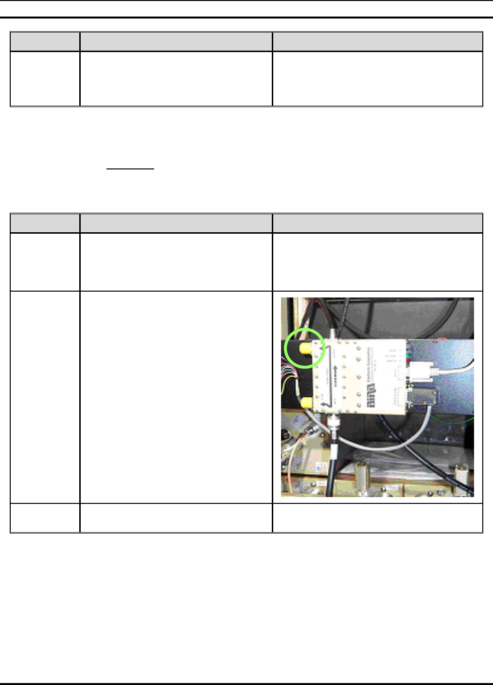
MM102225V1, Rev. B
56
STEPS ACTION MISCELLANEOUS
18.
Complete the summary acceptance table
confirming that the HPA transmit power
for each channel was set to provide the
site specified ERP.
6.8 HPA TX POWER BENCHMARKS – BIRD VSWR –57DBM
PORT (REQUIRED)
Objective: The objective of this test is to provide a reference power measurement for
each transmitter at the Bird Power Monitor (VSWR) –57dBm Port with the Bird Power
Monitor Output Port connected to the TX Antenna. This is a test port that can be used for
non-interfering measurement of transmitted power from all base stations.
STEPS ACTION MISCELLANEOUS
1.
DISABLE ALL OF THE HPA
OUTPUTS BEFORE PROCEEDING:
Set all of the HPA Enable/Disable
switches to the Disable position.
2.
Remove the HP 8920 test cable from the
Bird Power Monitor OUTPUT port and
connect it to the –57dB input coupler
port.
3. Connect the TX antenna jumper to the
Bird Power Monitor Output Port.
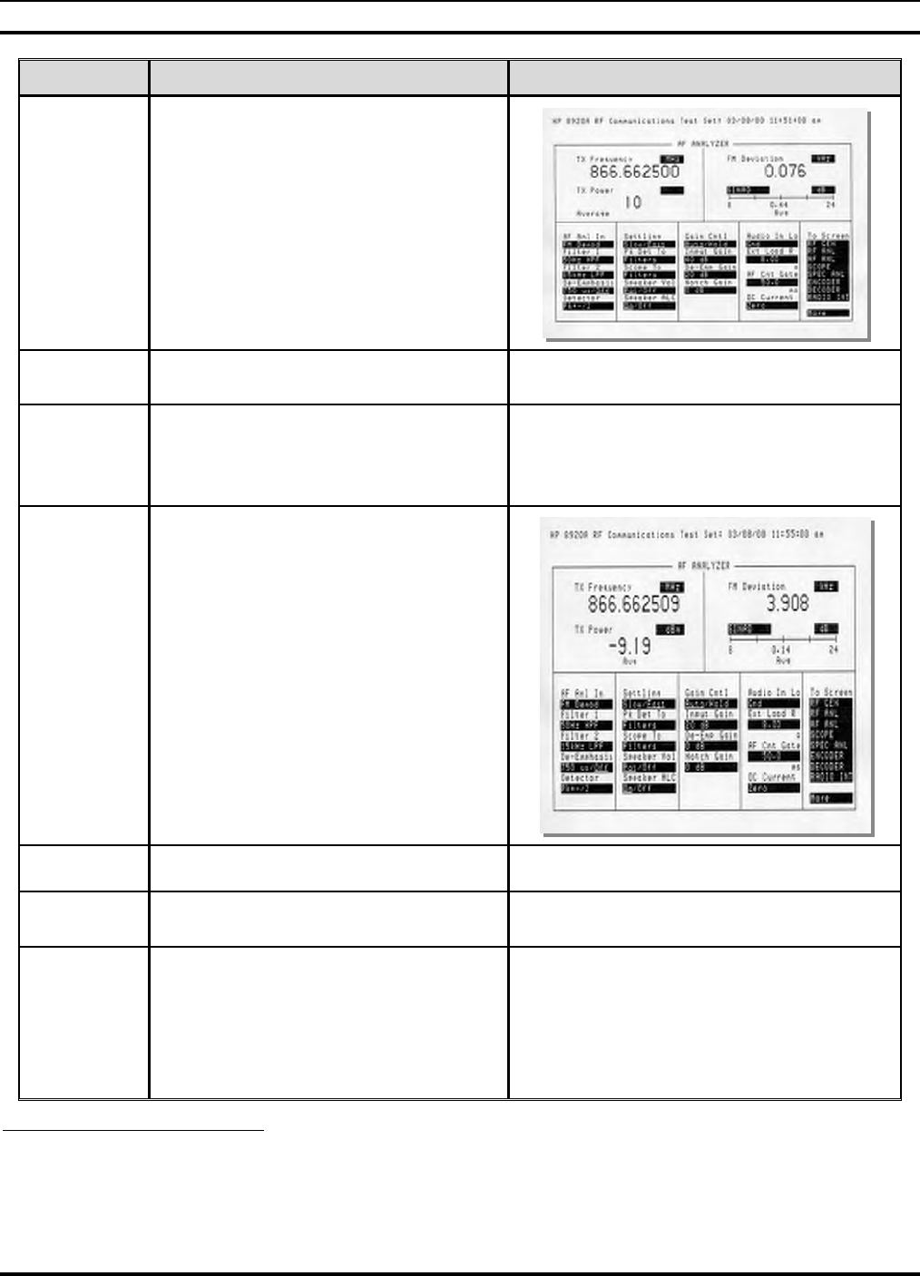
MM102225V1, Rev. B
57
STEPS ACTION MISCELLANEOUS
4.
Select the AF ANL screen and
configure the following settings:
• TX Power: dBm (Average 10)
• AF Anl In: FM Demod
• De-Emphasis: Off
• Detector: Pk+-/2
5. Set the HPA Enable/Disable switch to
the Enable position.
6.
Measure and record the TX Power from
the HP 8920 AF Analyzer screen on the
data collection sheet, factoring in the
additional loss of the test cable16.
7.
DISABLE THE HPA OUTPUT
BEFORE PROCEEDING:
Set the HPA Enable/Disable switch to
the Disable position.
8. Repeat for each RF path.
9. Record17 the data on the work collection
sheet.
10.
Measure and record the TX power with
channels 1 and 2 transmitting and
sequentially any additional channels at
the same time.
For example:
Channel 1 and 2 = -8 dBm
Channel 1, 2, and 3 = -6 dBm
Channel 1, 2, 3, and 4 = -4 dBm
Channel 1, 2, 3, 4, and 5 = -2 dBm
16 Refer to APPENDIX L - RECORDED DATA SHEET.
17 Refer to APPENDIX L - RECORDED DATA SHEET.

MM102225V1, Rev. B
58
STEPS ACTION MISCELLANEOUS
11. Record18 the results in table provided
with the data worksheet.
18 Refer to APPENDIX L - RECORDED DATA SHEET

MM102225V1, Rev. B
59
7.0 OPERATIONAL TESTING
7.1 STANDALONE SITE ACCEPTANCE (MANDATORY)
Objective: To verify correct functionality of the site in a standalone mode of operation.
Successful completion of this series of tests together with all preceding mandatory tests
will allow full operation of the site in standalone or repeater mode. This stage of site
certification permits its use in the event that backhaul communications are not available.
7.1.1 Preparation - Remove ALL Network Connectivity
STEPS ACTION MISCELLANEOUS
1. Ensure that all cables removed for
testing are re-connected for normal site
operation.
2. Disconnect cable from SAS CTRL 0
Port. Removes the T1 Network connectivity.
3. Disconnect the ISM Ethernet connection
if the site has an ISM option.
7.1.2 Procedure for Single Site Trunking
STEPS ACTION MISCELLANEOUS
1. Set all HPA ENABLE/DISABLE
switches to the ENABLE position.
2. Configure two mobile or portable
radios using the station parameters of the
site under test.
Radios should be set to factory default
configurations by removing record for
current OTP mode. ie: ATZ-1
**ERASERECORDMODE9
3. Power cycle the radios using their front
panel power switch and perform a unit-
to-unit test transmission.
4. Confirm default talk groups are
configured in the radios. *6# via DTMF M-803, P801.
5.
Enable all HPA’s. Select the same RF
channel and different talk groups for
both radios. Key the radio transmitters
simultaneously and verify one of the
radios trunks to a different RF channel.
Repeat for all RF channels allocated to
site.

MM102225V1, Rev. B
60
STEPS ACTION MISCELLANEOUS
6.
Disable all HPA’s except RF channel
under test. Select the RF channel under
test (C. U. T.) and different talk group
for both radios. Key the radio
transmitters simultaneously and verify
both stay on the same RF channel.
Repeat for all RF channels allocated to
site.
7.
Enable all HPA’s. Select different RF
channels and the same talk group for
both radios. Key the primary radio
transmitter and verify the secondary
mobile radio trunks to the same RF
channel as the primary radio. Key the
secondary radio transmitter and verify it
stays on the same RF channel it just
trunked to. Repeat for all RF channels
allocated to site.
7.2 NETWORK CONNECTIVITY - BACKBONE
COMMUNICATIONS (REQUIRED)
Objective: These tests verify the quality of the T1 link feeding the site and connectivity
to the Regional Operations Center serving the base site under test.
Required Test Equipment:
• PC running a suitable console emulation program
• Cisco “Black” test cable
• Cisco RJ45 to DB-9 terminal adapter
STEPS ACTION MISCELLANEOUS
1. Check the front panel of the Cisco 3600
access server and observe whether the
READY LED’s are illuminated.
2. Check the front panel of the Cisco 3600
access server and observe whether the
ACTIVE LED’s are flashing.
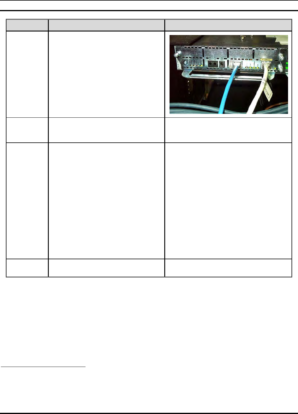
MM102225V1, Rev. B
61
STEPS ACTION MISCELLANEOUS
3.
Check the rear panel of the Cisco 3600
access server and observe whether the
Carrier Detect LED is lit and the
LOCAL and REMOTE ALARM
LED’s are off.
4. Connect the PC to the CON port of the
Cisco 3600 access server. This connector
is located on its front panel.
5.
Using address information given in the
regional IP Address Excel spreadsheet,
ping the MIS1 and MIS2 servers located
in the ROC. Commands and responses
are shown to the right.
buck40sas>ping 10.136.10.2119
Sending 5, 100-byte ICMP Echoes to
10.136.8.10, timeout is 2 seconds:
!!!!!
Success rate is 100 percent (5/5), round-trip
min/avg/max = 8/8/12 ms
buck40sas>ping 10.136.10.21
Sending 5, 100-byte ICMP Echoes to
10.136.8.11, timeout is 2 seconds:
!!!!!
Success rate is 100 percent (5/5), round-trip
min/avg/max = 8/12/24 ms
buck40sas>
6. Record the success or failure on
worksheet20.
19 "Buck40", where used in this manual, is only an example of the applicable code.
20 Refer to APPENDIX L - RECORDED DATA SHEET.

MM102225V1, Rev. B
62
7.3 T1 QUALITY LINK
Objective: The Cisco 3600 provides comprehensive monitoring capabilities for the T1
port that carries data traffic over the communications backbone. The showcontroller
command accumulates statistics over sixteen 15-minute intervals. This test does not form
part of the site acceptance testing but is included as a diagnostic tool to aid resolution of
link related issues.
STEPS ACTION MISCELLANEOUS
1. Allow the Unit to operate with the T1
connected for at least 5 minutes.
2.
Using a PC connected to the Cisco
CONSOLE port, enter the following
command from the enabled prompt:
buck40sas# show contr t1 1/0 [CR]21
The 3600 will respond with the Status
Information on the right.
T1 1/0 is up
Applique type is Channelized T1
Cable length is long gain36 0db
No alarms detected
Framing is ESF, Line Code is B8ZS, Clock
Source is Line
Data in current interval (741 seconds
elapsed):
0 Line Code Violations, 0 Path Code
Violations
0 Slip Secs, 0 Fr Loss Secs, 0 Line Err Secs,
0 Degraded Mins
0 Errored Secs, 0 Bursty Err Secs, 0
Severely Err Secs, 0 Unavail Secs
Data in Interval 1:
0 Line Code Violations, 0 Path Code
Violations
0 Slip Secs, 0 Fr Loss Secs, 0 Line Err Secs,
0 Degraded Mins
0 Errored Secs, 0 Bursty Err Secs, 0
Severely Err Secs, 0 Unavail Secs
Data in Interval 2:
0 Line Code Violations, 0 Path Code
Violations
0 Slip Secs, 0 Fr Loss Secs, 0 Line Err Secs,
0 Degraded Mins
0 Errored Secs, 0 Bursty Err Secs, 0
Severely Err Secs, 0 Unavail Secs
Continued
21 "Buck40", where used in this manual, is only an example of the applicable code.

MM102225V1, Rev. B
63
Continued
STEPS ACTION MISCELLANEOUS
Data in Interval 14:
0 Line Code Violations, 0 Path Code Violations
0 Slip Secs, 0 Fr Loss Secs, 0 Line Err Secs, 0
Degraded Mins
0 Errored Secs, 0 Bursty Err Secs, 0 Severely Err
Secs, 0 Unavail Secs
Data in Interval 15:
0 Line Code Violations, 0 Path Code Violations
0 Slip Secs, 0 Fr Loss Secs, 0 Line Err Secs, 0
Degraded Mins
0 Errored Secs, 0 Bursty Err Secs, 0 Severely Err
Secs, 0 Unavail Secs
Data in Interval 16:
35361 Line Code Violations, 46606 Path Code
Violations
1 Slip Secs, 13 Fr Loss Secs, 1 Line Err Secs, 0
Degraded Mins
0 Errored Secs, 0 Bursty Err Secs, 0 Severely Err
Secs, 13 Unavail Secs
Total Data (last 16 15 minute intervals):
35361 Line Code Violations, 46606 Path Code
Violations,
1 Slip Secs, 13 Fr Loss Secs, 1 Line Err Secs, 0
Degraded Mins, 0 Errored Secs, 0 Bursty Err
Secs, 0 Severely Err Secs, 13 Unavail Secs
buck40sas#
7.4 FINAL DEPARTURE CHECK
Objective: To ensure that the site is ready for on-line operation and that it can recover
automatically from a catastrophic power failure.
Required Test Equipment:
• PC with suitable console application
• Cisco “Black” Cable
• Cisco RJ45 to DB-9 adapter

MM102225V1, Rev. B
64
7.4.1 Power Failure
STEPS ACTION MISCELLANEOUS
1. Connect the PC to the TERMINAL port
of the DCX.
2. Type the command: opred ? [CR]
3. The DCX will respond with the
information on the right.
Manadabs2> opred?
OPRED: BssN Status: Socket: 7 MCAddr:
225.1.2.35[6801] Cond: 1
OPRED: SasN Status: Socket: 8 MCAddr:
225.1.1.32[6802] Cond: 1
OPRED: Device Status: BSC:Up
HPA:Keyed BSX:Up BSIB:Undef
OPRED: Expected/Actual Peers - Normal:
1/1 Standbys: 0/0 MCD: 2
OPRED: Operating State: Normal Mode:
0x3e Does Standby: 0
OPRED: SCI CHN CDS BSC HPA BSX
BSS_Address SAS_Address Reach
OPRED: 2 2 68 Up Keyed Up
172.18.16.168 172.18.112.202 0xb
OPRED: 1 1 68 Up Keyed Up
172.18.16.167 172.18.112.201 0xb
OPRED: -------
OPRED:
OK
4. Verify that the items shown in bold are
indicated.
5. Turn off all circuit breakers feeding both
racks of equipment.
6. Wait for 30 seconds before reverting all
breakers to the ON position.
7. Verify that all equipment powers up.
8. Verify MES registration.
9. Repeat Steps 2 and 3 to verify the data
once more.

MM102225V1, Rev. B
65
7.4.2 Multi Site Trunking
STEPS ACTION MISCELLANEOUS
1. Verify all HPA ENABLE/DISABLE
switches to the ENABLE position.
2.
Configure two mobile radios using the
station parameters of the site under test.
3. Power cycle the radios using their front
panel power switch.
4. Unit to Unit Call
5. Trunk Call to another site.
6. Multi Site Trunking

MM102225V1, Rev. B
66
8.0 COMMON TERMS
The following brief explanations describe OpenSky Base Station rack components and
define other common terms:
Table 8-1: Common Terms
TERM ACRONYM OR
ALIAS DEFINITION
Alarm Module ION Environment and equipment monitor with network or pager
alarm capability, providing detection of out-of-specification
conditions.
Device used initially: ION Networks, Inc.: Sentinel 2000
Slimline
Antenna Device that transmits or receives electromagnetic radiation at
radio frequencies.
Antenna cable
(Feedline) Coaxial cable used to connect a transmitter and/or receiver to
its antenna.
Base Station
Controller BSC The BSC is part of the Digital Controller/(X)transceiver
(DCX).
Base Station
Transceiver BSX The BSX is part of the Digital Controller/(X)transceiver
(DCX).
Bus That part of a circuit used in common by several units or
modules.
The main power lead in a rack or cabinet of equipment.
Cisco Router Network Access
Server TCP/IP internetworking router connecting base site to the
OpenSky Network.
Control Cable
(Tower Top
Amplifier)
Five-conductor cable connected between TTA and Control
Unit. Provides voltage/current read out of TTA, alarm status,
and switching between primary and secondary amps.
Combiner Device to combine transmission signals from base site
transmitters before sending to the antenna for transmission.
Duplexer Used for single-antenna sites, a device to allow simultaneous
transmission and reception over a single antenna.
Feedline Transmission line that delivers RF power to an antenna or
between an antenna and a radio transmitter or receiver.
High-Power
Amplifier HPA Device to amplify the frequency-modulated signal for
transmission.
InterModulation IM The production, in a nonlinear element of a system, of
frequencies corresponding to the sum and difference
frequencies of the fundamentals and harmonics thereof that are
transmitted through the element.

MM102225V1, Rev. B
67
TERM ACRONYM OR
ALIAS DEFINITION
InterModulation
Rejection IMR The reject to the production, in a nonlinear element of a
system, of frequencies corresponding to the sum and
difference frequencies of the fundamentals and harmonics
thereof that are transmitted through the element.
ISM Controller
(BackHaul
Router)
Control unit used to process data from the tower-top-
mounted Industrial, Scientific, and Medical (ISM)
transceiver.
(ISM is a license-free RF communications band; 2.4 GHz
and 5.8 GHz.)
Lightning
Arrester Protective device that provides a low impedance path to
ground for surge protection against dangerous voltages such
as lightning.
Low Noise
Amplifier LNA See Tower Top Amplifier.
Multicoupler Device to amplify and separate signals, used for single-
antenna sites.
Reception Signal
Splitter RX Splitter Passive device used with multiple receivers.
Network Access
Server Cisco Router TCP/IP internetworking router connecting base site to the
OpenSky Network.
Device used initially: Cisco Router, Model 3600
Noise and
InterModulation
Cascade Analysis
System
NIMCAS Program used to predict the expected difference in 20 dB
quieting measurements for terminated and feedline
connected results.
PolyPhaser® Producer of lightning arrester devices for surge protection.
Radio Frequency RF That portion of the electromagnetic energy spectrum used
for radio signal transmission and reception.
Receive;
Reception RX The action or process of selecting and decoding transmitted
RF signals using particular frequencies to reconstruct the
information transmitted.
Site Access
Server SAS
Tower-Top
Amplifier Low
Noise Amplifier
TTA or TTLNA Used with receive only antenna installations (TX/RX
Systems, Inc.).
Transmit;
Transmission TX The action or process of coding information in the form of
RF signals, using particular frequencies to make it available
for reception.
TX/RX Hybrid
Power Divider An amplifier installed in conjunction with a Tower Top Amp
to feed additional receivers.

MM102225V1, Rev. B
68
TERM ACRONYM OR
ALIAS DEFINITION
TX/RX Isolator Prevents reflection of RF energy back into the RF source
(the transmitter).
Voltage Standing
Wave Ratio
Monitor
VSWR Monitor Placed in the antenna feed circuit, it continuously monitors
the forward and reverse power using a directional coupler.

MM102225V1, Rev. B
69
This page intentionally left blank
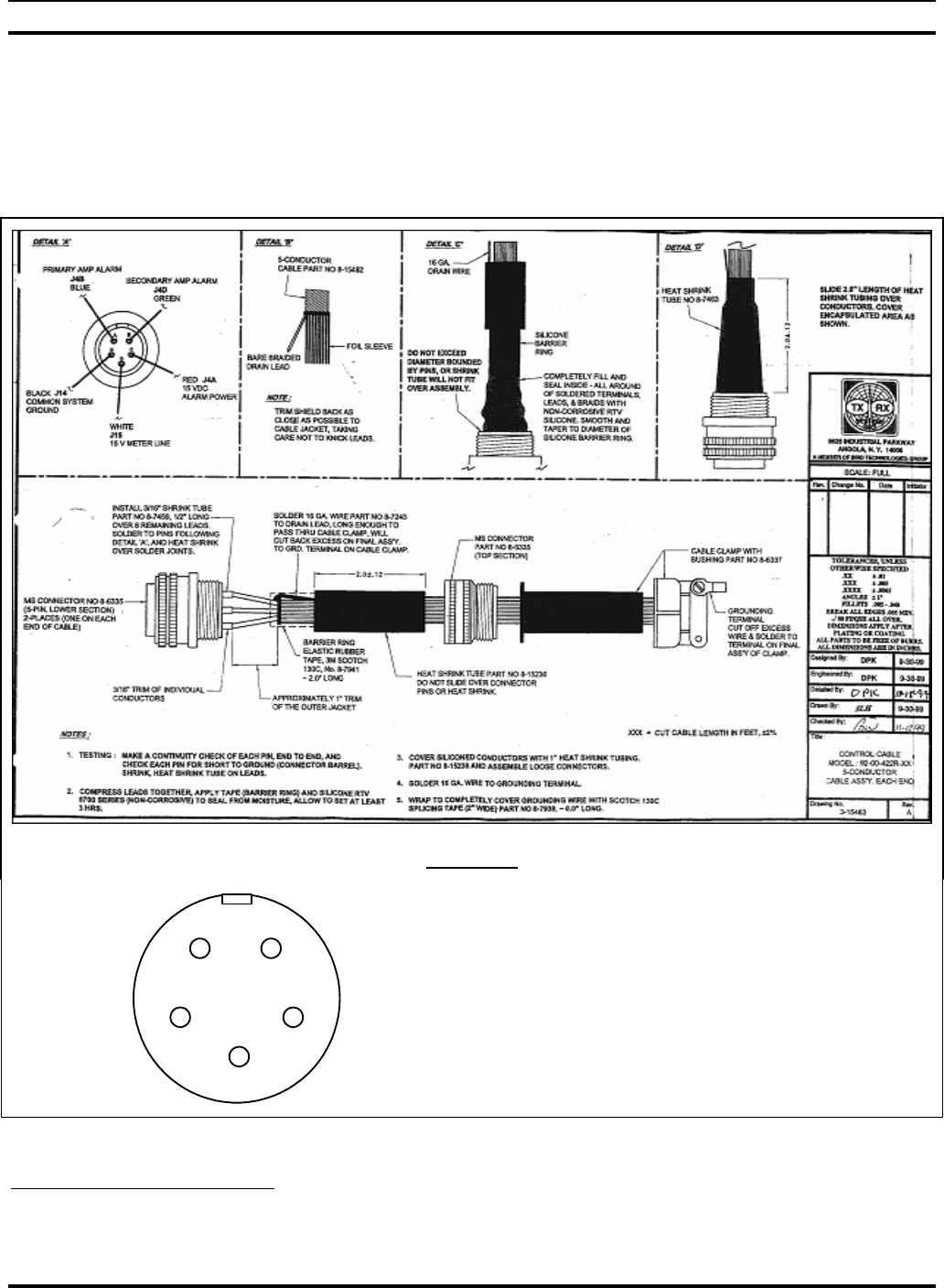
MM102225V1, Rev. B
70
APPENDIX A
ATTACHING MIL-SPEC (MS) CONNECTOR TO END OF CONTROL
CABLE/SOLDERING TOWER TOP AMPLIFIER CONTROL CABLE22
Detail “A”
D
A
E
B
C
A – PRI ALARM (Blue)
B – SEC. ALARM (Green)
C – ALM POWER (Red)
D – METER LINE (White)
E - GROUND
22 Taken from M/A-COM, Inc. Drawing No. GTP-0296

MM102225V1, Rev. B
71
This page intentionally left blank

MM102225V1, Rev. B
72
APPENDIX B
CONNECTING A PC TO A BASE STATION23
There are three ways to connect a personal computer to OpenSky Base Station equipment:
1. Direct connection to the RS-232 port of the device under test.
2. Direct connection to the Console Port of the Access Server and telnet to the device under test.
3. Direct connection to the Ethernet port of the Access Server and telnet to other devices.
Direct connection to any device is the simplest approach, but requires cables to be swapped and various
configurations for the terminal emulation application used as the PC user interface. The table below
provides connection details for all rack equipment.
EQUIPMENT SERIAL/
PORT RATE CABLE TELNET
AVAILABLE
DCX/BSC Yes/ Terminal
DB9 19200 Null/or Cisco
Black Cable Yes Via Cisco
Cisco Router Yes/ CON(sole)
RJ45 9600 Cisco Black
Cable with RJ45
to DB9 Female
adapter for PC
end.
Yes
DPS Alarm Yes/ Aux DB9 9600 DB9 F-M Yes Via Cisco
ION Alarm Yes/ Aux DB9 9600 DB9 F-M Yes Via Cisco
Bird Power Mon Yes/ RS-232
DB9 via Front
Panel Connector
on DPS or ION
Alarm.
9600 DB9 F-M Yes available on
ION Box
23 Taken from M/A-COM, Inc. Drawing No. GTP-0296, Rev. A.

MM102225V1, Rev. B
73
This page intentionally left blank

MM102225V1, Rev. B
74
APPENDIX C
EQUIPMENT SERIAL NUMBERS24
RACK EQUIPMENT SERIAL NUMBER
1 Alarm
1 DCX 1
1 DCX 2
1 DCX 3
1 Cisco
2 Bird Power Mon
2 TTA Controller
2 HPA 1
2 HPA 2
2 HPA 3
1 RCVR Multicoupler
24 Taken from M/A-COM, Inc. Drawing No. GTP-0296, Rev. A.

MM102225V1, Rev. B
75
This page intentionally left blank

MM102225V1, Rev. B
76
APPENDIX D
SITE ACCESS SERVER CONFIGURATION25
PARAMETER & VALUE EXPLANATION
buck40sas#show run
Building configuration
Current configuration:
!
version 12.0
service timestamps debug uptime
service timestamps log uptime
no service password-encryption
!
hostname buck40sas
!
enable secret 5 $1$ZKEn$1ZY/cQ0ILIKvSDh/sODJT0
!
!
!
!
!
ip subnet-zero
no ip domain-lookup
!
ip multicast-routing
ip dvmrp route-limit 20000
!
!
controller T1 1/0
framing esf
linecode b8zs
channel-group 0 timeslots 1-4 speed 64
25 Taken from M/A-COM, Inc. Drawing No. GTP-0296, Rev. A.

MM102225V1, Rev. B
77
PARAMETER & VALUE EXPLANATION
!
process-max-time 200
!
interface Loopback0
ip address 10.136.24.158 255.255.255.224
no ip directed-broadcast
ip pim dense-mode
no ip mroute-cache
!
interface Loopback1
ip address 10.136.24.190 255.255.255.224
no ip directed-broadcast
!
interface FastEthernet1/0
ip address 10.136.24.222 255.255.255.224
no ip directed-broadcast
!
interface Serial1/0:0
ip unnumbered Loopback0
no ip directed-broadcast
fair-queue 64 256 0
!
interface Async1
ip unnumbered Loopback0
no ip directed-broadcast
ip pim dense-mode
no ip mroute-cache
async mode dedicated
!
interface Async2
ip unnumbered Loopback0
no ip directed-broadcast
ip pim dense-mode
no ip mroute-cache
async mode dedicated

MM102225V1, Rev. B
78
PARAMETER & VALUE EXPLANATION
!
interface Async3
ip unnumbered Loopback0
no ip directed-broadcast
ip pim dense-mode
no ip mroute-cache
async mode dedicated
!
interface Async6
ip unnumbered Loopback1
no ip directed-broadcast
ip pim dense-mode
no ip mroute-cache
async mode dedicated
!
interface Async7
ip unnumbered Loopback1
no ip directed-broadcast
ip pim dense-mode
no ip mroute-cache
async mode dedicated
!
interface Async8
ip unnumbered Loopback1
no ip directed-broadcast
ip pim dense-mode
no ip mroute-cache
async mode dedicated
!
interface Async11
no ip address
no ip directed-broadcast
async mode interactive
!
interface Async12

MM102225V1, Rev. B
79
PARAMETER & VALUE EXPLANATION
no ip address
no ip directed-broadcast
async mode interactive
!
interface Async13
no ip address
no ip directed-broadcast
async mode interactive
!
interface Async15
ip unnumbered Loopback1
no ip directed-broadcast
async mode dedicated
!
interface Async16
ip unnumbered Loopback1
no ip directed-broadcast
encapsulation ppp
shutdown
async mode dedicated
!
ip classless
ip route 10.136.8.0 255.255.252.0 Serial1/0:0
ip route 10.136.24.129 255.255.255.255 Async1
ip route 10.136.24.130 255.255.255.255 Async2
ip route 10.136.24.131 255.255.255.255 Async3
ip route 10.136.24.161 255.255.255.255 Async6
ip route 10.136.24.162 255.255.255.255 Async7
ip route 10.136.24.163 255.255.255.255 Async8
ip route 10.136.24.188 255.255.255.255 Async15
ip route 10.136.24.189 255.255.255.255 Async16
no ip http server
!
dialer-list 1 protocol ip permit
dialer-list 1 protocol ipx permit

MM102225V1, Rev. B
80
PARAMETER & VALUE EXPLANATION
snmp-server engineID local
000000090200003080C45CA0
snmp-server community public RO
!
line con 0
exec-timeout 0 0
transport input none
stopbits 1
flowcontrol hardware
line 1 10
stopbits 1
speed 38400
line 11 14
transport preferred telnet
transport input telnet
transport output none
telnet speed 19200 19200
stopbits 1
line 15
transport preferred telnet
transport output none
stopbits 1
speed 38400
line 16
autoselect ppp
stopbits 1
flowcontrol software
line aux 0
exec-timeout 0 0
transport preferred telnet
transport input all
stopbits 1
speed 38400
flowcontrol hardware
line vty 0 4

MM102225V1, Rev. B
81
PARAMETER & VALUE EXPLANATION
password cisco
login
!
end
buck40sas#

MM102225V1, Rev. B
82
APPENDIX E
TYPICAL MOBILE CONFIGURATION26
AVAILABLE CHANNEL: OT400:s400,601 OT460:s460,102
AVAILABLE CHANNEL: OT500:s500,602 OT560:s560,603
AVAILABLE CHANNEL: TYCO9:s708,202
CURRENT CHANNEL: OT560:s560,603
HOME CHANNEL: OT400:s400,601
TUNING MODE: 0
ECHO: 1
SIDE TONE: 1
SAVE CONTROL: 2
CALIBRATION VALUES: FACTORY: 1100,300,31076,32676,32767,100
CALIBRATION VALUES: USER: 1100,300,31076,32676,32767,100
TRANSMIT_POWER: 45
VOLUME: 9
BRIGHTNESS: 1
CONTRAST: 1
IP ADDRESS: 148.174.106.4
BROADCAST IP ADDRESS: 148.174.106.254
SERVICE ADDRESS: 199.81.106.100
SERVICE PORT: 6425
MODE: 9
SHUTDOWN TIMER: 120
User ID: 2
Station ID:
AutoRegistration: 1
AutoProvisioning: 0
Auto-Online Command: ato
Delay Host Ready: 0
Side Tone Level: 16384
Roam Tone Level: 1500
Grant Tone Level: 1500
Enable Secondary Registration: 1
TNIC ADDRESS: 148.174.104.71
26 Taken from M/A-COM, Inc. Drawing No. GTP-0296, Rev. A.

MM102225V1, Rev. B
83
TNIC PORT: 5766
DIPP Format: 0
USE DTR/DSR: 1
AUDIO INPUT: 0
AUDIO OUTPUT: 0
SCAN MODE: 0
Enable Data Registration: 1
Voice Re-registration Timer: 40
Voice Re-registration Count: 2
Enable Voice Registration: 1
Queue Timer: 10
Emergency Timer: 5
Start Profile Number: 0
VCO Calibration(CF_ADJUSTMENT): 0
Save VCO Calibration: 0
Fix the voice AGC gain: 0
Sync loss report mark: 17
VERBOSITY: 1
OK

MM102225V1, Rev. B
84
APPENDIX F
TYPICAL BASE STATION CONFIGURATION27
manadabs2> at&v
BSC INFORMATION: S/N: 000000010005
BSC INFORMATION: BSC S/W Version: BSC-1000 Version OTP 4.00 Sep 28
1999 14:58:02
BSC INFORMATION: BSC H/W Version: 50 MHz NGP Rev B with 1M of
Memory
BSC INFORMATION: M/A-COM HPA Version: 0.01e
BSC INFORMATION: M/A-COM HPA Product String: 13-09-99 (0x01, 0x02)
BSC INFORMATION: M/A-COM HPA Serial Number: 00000101
BSC INFORMATION: MACOM BSX Version: 802: 19 09/03/99
BSC INFORMATION: MACOM BSX Serial Number: 000000010004
Switch to Another Process:
BSC I/P Address: 172.18.16.168
MDIS I/P Address: 172.18.16.200
MDIS PORT: 16962[4242]
Voice Grant Timeout: 0[0]
Null Voice Frame Limit (missed end): 15[f]
Null Voice Frame Limit (after grant): 15[f]
Null Voice Frame Limit (after trunk): 20[14]
MSF Pause Interval: 3600[e10]
MSF Pause Duration: 0[0]
Set Channel Characteristics: MANA2[0 698]: Col:[1 4]/4/2 402 2 0
(0.0000,0.0000)
Change Slip Interface Rate: 38400[9600]
RSSI Hysteresis Value: 8[8]
RSSI Scan Time: 90[5a]
RSSI Scan Delta: 8[8]
RSSI Average Time: 5[5]
BLER Threshold: 10[a]
BLER Average Time: 5[5]
CBLER Threshold: 20[14]
CBLER Average Time: 10[a]
RRM CSI Epoch: 60[3c]
27 Taken from M/A-COM, Inc. Drawing No. GTP-0296, Rev. A.

MM102225V1, Rev. B
85
RRM Cell Configuration Epoch: 30[1e]
RRM Quality Parameters Epoch: 120[78]
RRM RC Roaming Epoch: 10[a]
RRM RC Roaming Parameters: 80[50] 40[28] 2[2] 25[19] 10[a]
RRM RC Utilization Epoch: 0[0]
RRM Utilization Roaming Parameters: 10[a] 40[28] 0[0] 60[3c] 30[1e]
RRM Deactivation Roaming Parameters: 4[4]
NMS Port: 6100[17d4]
Deviation Scale Factor: 1.000
Output Mode: 1[1]
I/Q Max Deviation: 4000[fa0]
I/Q Offsets: 70[46] -130[ffffff7e]
I/Q Vector: 32767[7fff] 32067[7d43] 32767[7fff]
0[0]
I/Q Amplitude: 16384[4000]
BSC TYPE: 2[2]
BSX oven oscillator warm-up time: 5[5]
RPS I/P Address: 0.0.0.0
RPS PORT: 6222[184e]
Tracking Receive (net->bs) PORT: 6667[1a0b]
HPA Power Level: 44.900 [Current: 44.800]
Reset RRM Parameters to Defaults:
Show Adjacent Channels: MANA1[0 794]: Col:[1 4]/4/1 401 2 0
(0.0000,0.0000)
Add Adjacent Channel:
Remove All Adjacent Channels:
Remove Specific Adjacent Channels:
TNIC I/P Address: 172.18.16.200
TNIC Receive/Send PORT: 5762[1682]
OpenSky NMS Port: 6102[17d6]
Define NMS Trap Target: 0: 172.18.16.205,4000,0xffff
Define NMS Trap Target: 1: 0.0.0.0,0,0xffff
Define NMS Trap Target: 2: 0.0.0.0,0,0xffff
Define NMS Trap Target: 3: 0.0.0.0,0,0xffff
Define NMS Trap Target: 4: 0.0.0.0,0,0xffff
Set NMS Operating Mode: 62 [0x3e]
BSC Local Network I/P Address: 172.18.112.202
BSC Local Network Netmask: 255.255.240.0

MM102225V1, Rev. B
86
Dispatch Network Netmask: 255.255.240.0
Peer Port: 6800[1a90]
Redundancy SAS Multicast Address: 225.1.1.32
Redundancy SAS Multicast Port: 6802[1a92]
Redundancy BSS Multicast Address: 225.1.2.35
Redundancy BSS Multicast Port: 6801[1a91]
Redundancy Peers: 1[1]
Redundancy Standbys: 0[0]
Redundancy Peer Heartbeat Timeout: 10[a]
Redundancy Peer Query Timeout: 5[5]
Redundancy Discovery Timeout: 90[5a]
Redundancy Device Query Timeout: 10[a]
Channel ID: 2[2]
Site Component ID: 2[2]
BSC Does Standby: 0[0]
Both network links fail option: 0[0]
Terminal prompt: manadabs2>
Over the network download port: 6425[1919]
Private Voice Group Boundary: 2000
Emergency Priority Boundary: 4
Default Voice Group info: private VG PRI:14, HT:0 sec. public
VG PRI:16, HT:0.
Voice Group Delete:
Voice Group Add: 0: 101 2 30
Voice Group Add: 1: 102 4 30
Voice Group Add: 2: 201 6 10
Voice Group Add: 3: 301 6 0
Voice Group Add 4: 302 6 0
Voice Group Add: 5: 303 6 0
Voice Group Add: 6: 304 6 0
Voice Group Add: 7: 305 6 0
Voice Group Add: 8: 401 8 0
Voice Group Add: 9: 402 8 0
Voice Group Add: 10: 403 8 0
Voice Group Add: 11: 404 8 0
Voice Group Add: 12: 405 8 0
Voice Group Add: 13: 501 10 0
Voice Group Add: 14: 502 10 0
Voice Group Add: 15: 503 10 0

MM102225V1, Rev. B
87
Voice Group Add: 16: 504 10 0
Voice Group Add: 17: 505 10 0
BSIB is present: 0[0]
BSIB should key: 0[0]
** NOT USED **: 0[0]
BSIB VSWR Alarm Levels: 0.000 1.200 0.000 0.000 0.000 1.200
BSIB power Alarm Levels: 0.000 0.000 0.000 0.000 0.000 0.000
RX I/F Eq Tap: 7000[1b58]
Dataflow Mark: 60[3c]
Redundancy disable: 0[0]
MAC continuity sum: 15[f]
VERBOSITY : 1[1]
OK

MM102225V1, Rev. B
88
APPENDIX G
TVARB STATUS28
TVARB show the status of the Transmit Voice Channel ARBitration (TVARB) process. Returned
parameters provide useful insight to voice channel access information allowing system problems to be
readily diagnosed.
manadabs2> tvarbstate
*************************************************************
num BSCs this site: 2 snooping: OFF
bsc_info[0]= sci:2 chid:2 free_rev:2 free_fwd:2
bsc_info[1]= sci:1 chid:1 free_rev:2 free_fwd:2
free_rev_slots_site: 4
free_fwd_slots_site: 4
*************************************************************
OK
manadabs2> tvarbvg2
*************************************************************
current number of queued requests: 0 max. number of queued requests: 0
state->next_rev_res_ctl entries: 0
state->new_tams_ctl entries: 0
state->active_tams_ctl entries: 0
state->deleted_tams_ctl entries: 0
bsc[0] {chnid:2 nports:2 free_fwd:2 free_rev:2}
bsc[1] {chnid:1 nports:2 free_fwd:2 free_rev:2}
TVARB: current calls:
private_public_group_boundary: 2000
emergency_priority_boundary: 4
default PRIVATE_VG priority: 14
default PRIVATE_VG hang time: 0 sec.
default PUBLIC_VG priority: 16
default PUBLIC_VG hang time: 0 sec.
maximum_grant_time: 0 sec.
*************************************************************
OK
Test Cables:
28 Taken from M/A-COM, Inc. Drawing No. GTP-0296, Rev. A.

MM102225V1, Rev. B
89
Cable 1
Cisco black RJ45 to RJ45 Modular
Cisco Terminal Adapter RJ45 to 9-Pin D Shell (F)
Cables 2 & 3
Qty 2 BNC to N for in rack distribution losses.
Qty1 N-N (F/F) barrel for in rack distribution losses
HPA output power
Cables 2 & 3
SMA (F) to N (M) to attach to HPA
N F-F Barrel to attach to high power side of load.
BNC to N to attach cable 3 to RF input of HP 8920

MM102225V1, Rev. B
90
APPENDIX H
VERIFICATION TESTING – TRANSMIT FILTER TUNING29
Installed Site Cavity Tuning Procedure should also be consulted for Filter Tuning.
1. Installed Site Cavity Tuning Procedure.
2. Power on Agilent® 8920. Select RF GEN from TO SCREEN.
3. Set RF Gen Freq to frequency cavity is to be tuned to.
4. Set AMPLITUDE to -10 dBm.
5. Set Output Port to RF Out.
6. Set AF Gen1 to Off.
7. Select SPEC ANL from TO SCREEN.
8. Select ANT from CONTROLS.
9. Set REFERENCE LEVEL to 0.0 dBm.
10. Keep SPAN at 0.200000 MHz.
11. Set LVL AVG to 20.
12. Connect RF cable from Agilent 8920 RF OUT port to combiner Isolator Input port and connect an RF
cable from the combiner Airline Output port to the Agilent 8920 ANTENNA IN port. Use calibrated
RF cables from the service monitor pack.
13. If signal is not seen at this span set in step 9, widen span to 5 MHz and a coarse tune adjustment will
need to be made.
14. Remove protective sleeve from coarse tune plunger and loosen setscrew. Loosen lock nut for fine
tune plunger. (NOTE: Use only the fine tune plunger if checking cavity for a drift.)
15. Position fine tune plunger mid-range before adjusting coarse tune plunger. Position coarse tune
plunger to generate maximum spectrum amplitude on display. If plunger refuses to move, tap on it
with handle end of screwdriver.
16. Tighten setscrew on coarse plunger and reinstall protective sleeve.
17. Position fine tune plunger to maximize spectrum amplitude on display.
18. Tighten fine tune plunger lock nut.
19. Reconnect all cables.
20. Finished.
29 Taken from M/A-COM, Inc. Drawing No. GTP-0301, Rev. - .

MM102225V1, Rev. B
91
This page intentionally left blank

MM102225V1, Rev. B
92
APPENDIX J
INSTALLER PROFILE DATA SHEET
(One sheet per Installer if multiple Installers used)
INSTALLER PROFILE
Installer’s Company Name: __________________________________________
Installer’s Telephone Number: __________________________________________
Installer’s Name (s): __________________________________________
__________________________________________
Technician’s Name (s): __________________________________________
__________________________________________
Date of Testing Complete: __________________________________________
Test Equipment Used,
Model, Serial Number
and Calibration Date: __________________________________________
__________________________________________
__________________________________________
__________________________________________
__________________________________________
__________________________________________
__________________________________________

MM102225V1, Rev. B
93
This page intentionally left blank

MM102225V1, Rev. B
94
APPENDIX K
ANTENNA SYSTEM INSTALLATION CHECKLIST
(One sheet per antenna per site)
SITE ______________
ANTENNA ______________
INSPECTED BY ______________
DATE ______________
CHECKLIST:
1. Is this antenna for Transmit, Receive or GPS? TX RX
GPS
2. What is the make and model of antenna?
OMNI
DIRECTIONA
L
3. What is the type of antenna? ______________
4. What is the design gain of antenna? ______________ dB
5. What is the bearing of antenna relative to True North? ______________ deg
6. What is the height of antenna above ground? ______________ ft
7. What is the feedline make and type? ______________
8. What is the installed feedline length from antenna to building entrance? ______________ ft
9. Are hoisting grips installed as specified? YES NO
10. Is feedline secured to tower at specified intervals? YES NO
11. Is feedline grounded at top of tower? YES NO
12. Is feedline grounded at bottom of tower? YES NO
13. Is feedline grounded at point where it enters building? YES NO
14. Is feedline feed-through properly installed? YES NO
15. Are coaxial connectors weather-sealed? YES NO
16. Is feedline entrance weather-sealed? YES NO
17. Is the feedine connected to a surge protector inside the building? YES NO
18. Is the TTA control cable connected to a surge protector at the entrance port? YES NO

MM102225V1, Rev. B
95
This page intentionally left blank

MM102225V1, Rev. B
96
APPENDIX L
RECORDED DATA SHEET
(A separate data sheet is required for each channel)
Channel # ______________
Passive Antenna Sites
RMS audio voltage coming from the radio receiver
("Un-quieted” audio output level) ______________________________
Signal generator level at the 20dB quieting level
with the antenna not attached __________________________________
20dB quieting level with the antenna attached ____________________
Analog Receive Tests
12dB SINAD Receiver Sensitivity
RF Signal Generator Amplitude (For 12dB SINAD) _______________
Tower Top Amplifier Low Noise Amplifier (TTALNA) Gain
Measurement
Power level as indicated in the HP 8920 Spectrum Analyzer
Lvl field (On) ___________________ (Off)______________________
Resulting Gain __________________ (On minus Off)
Antenna 20dB Quieting Test
AC Level ___________________________________
New 20dB quieting AC Level with associated
RF input level.________________________________
20dB de-sense value:
Channel ______________________________
TX Frequency shown on Analyzer (Total must be + 200 Hz):
Channel ______________________________
Transmit Deviation
FM Deviation ________________________________
Final HPA TX Power level _____________________
TX Power from the HP 8920
AF Analyzer screen ___________________________
TX Power with channels 1 and 2 transmitting and sequentially any additional channels at
the same time ________________________________

INSTALLATION CHECKLIST
MM102225V1 R1A 97
Network Connectivity
Ping the MIS1 and MIS2 servers located in the ROC.
Success__________________ Failure ____________________

MM102225V1, Rev. B
98
This page intentionally left blank

M/A-COM Wireless Systems
221 Jefferson Ridge Parkway
Lynchburg, Virginia 24501
(Outside USA, 434-385-2400) Toll Free 800-528-7711
www.macom-wireless.com Printed in U.S.A.