HARRIS MTT-A025 ISM Radio User Manual CERTIFICATE OF COMPLIANCE
Harris Corporation ISM Radio CERTIFICATE OF COMPLIANCE
UserManual.wiki
>
HARRIS
>
MTT-A025 User Manual
>
Manual revised
Contents
1.
Users Manual
2.
Manual revised
Manual revised
Navigation menu
Upload a User Manual
Namespaces
Wiki Guide
HTML
PDF
Info
Views
User Manual
Discussion / Help
Navigation

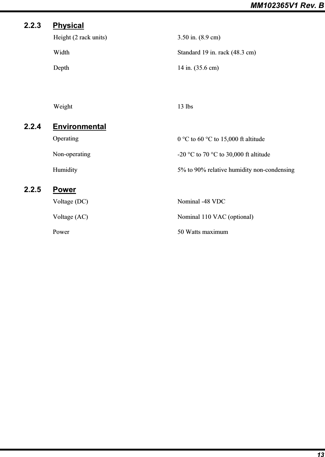
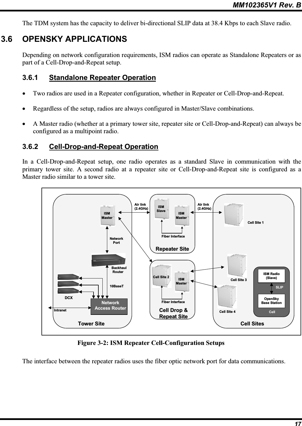
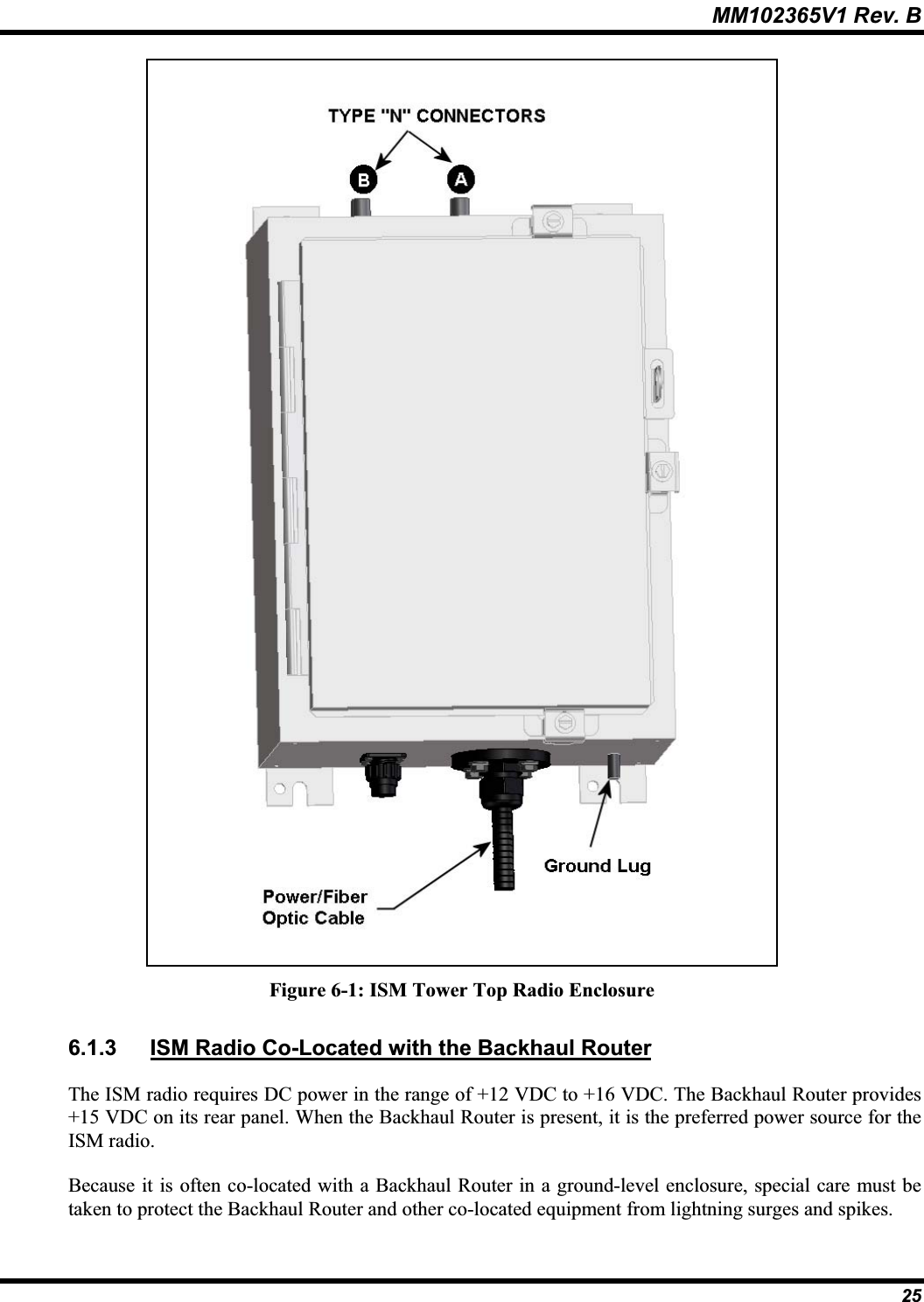
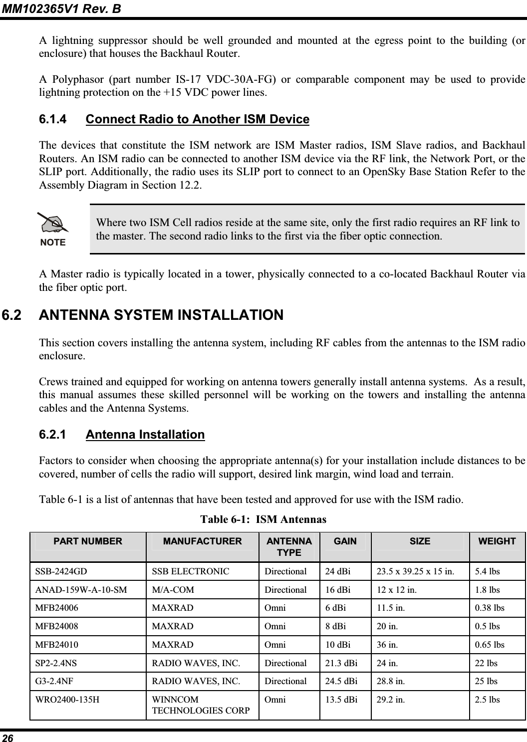
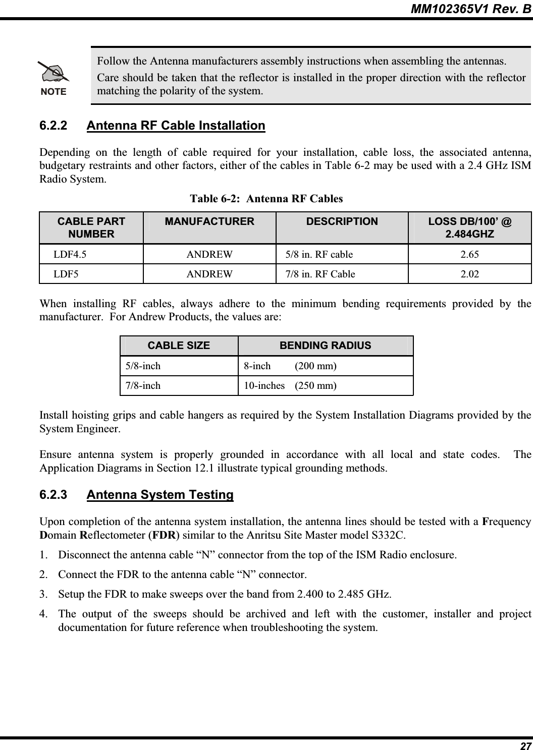
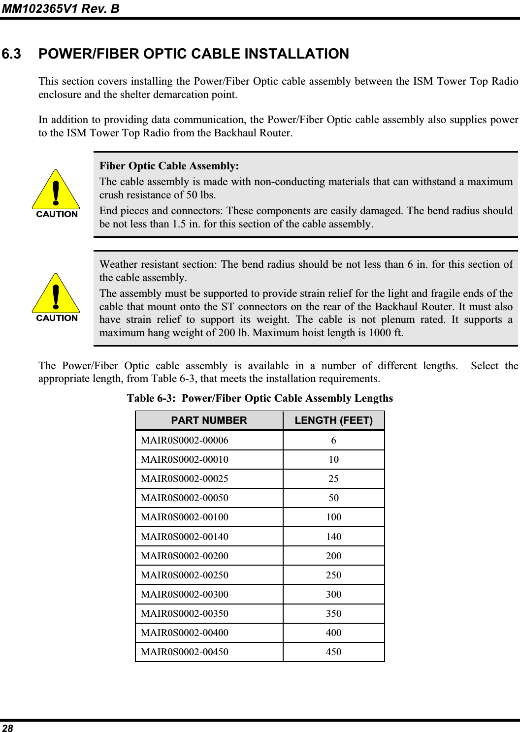
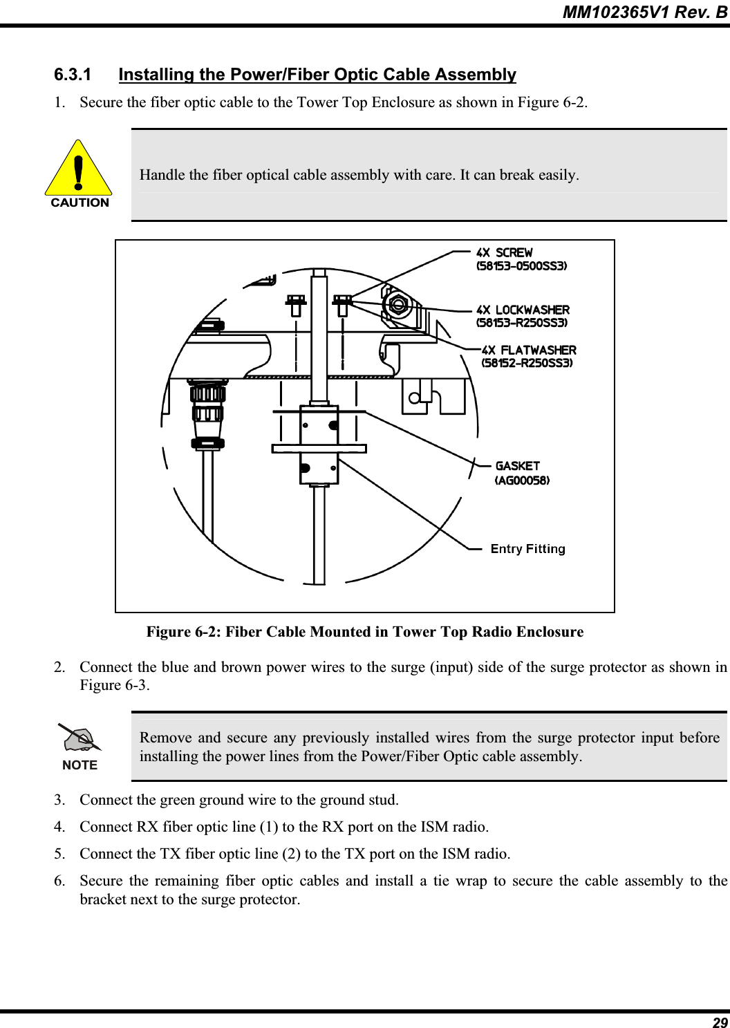
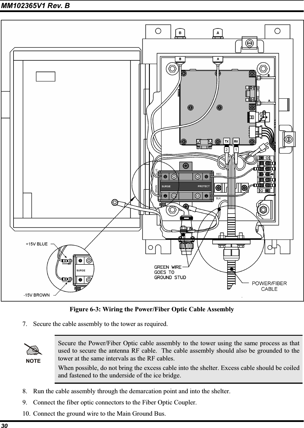
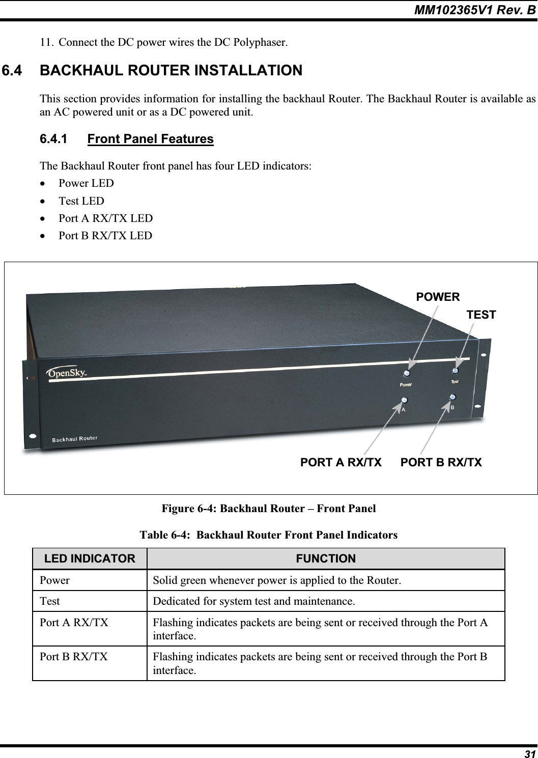
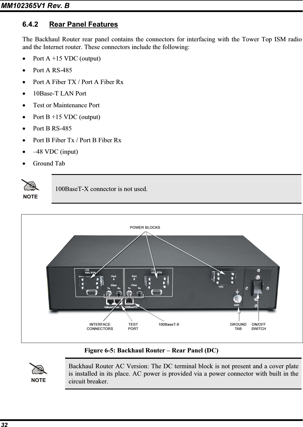
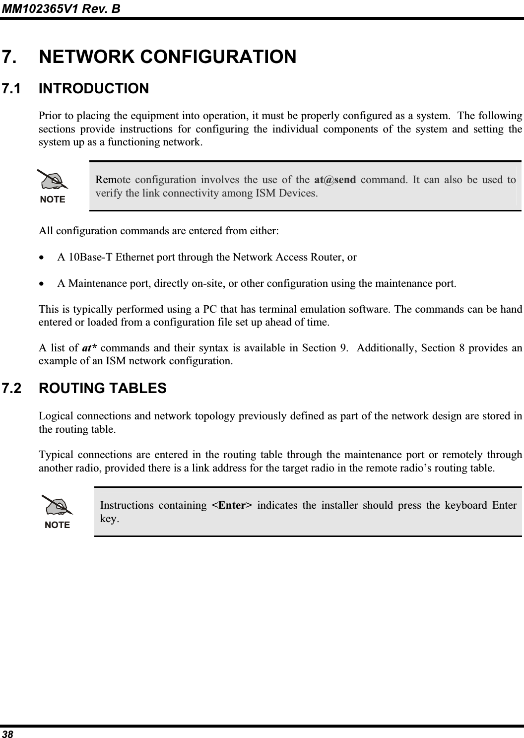
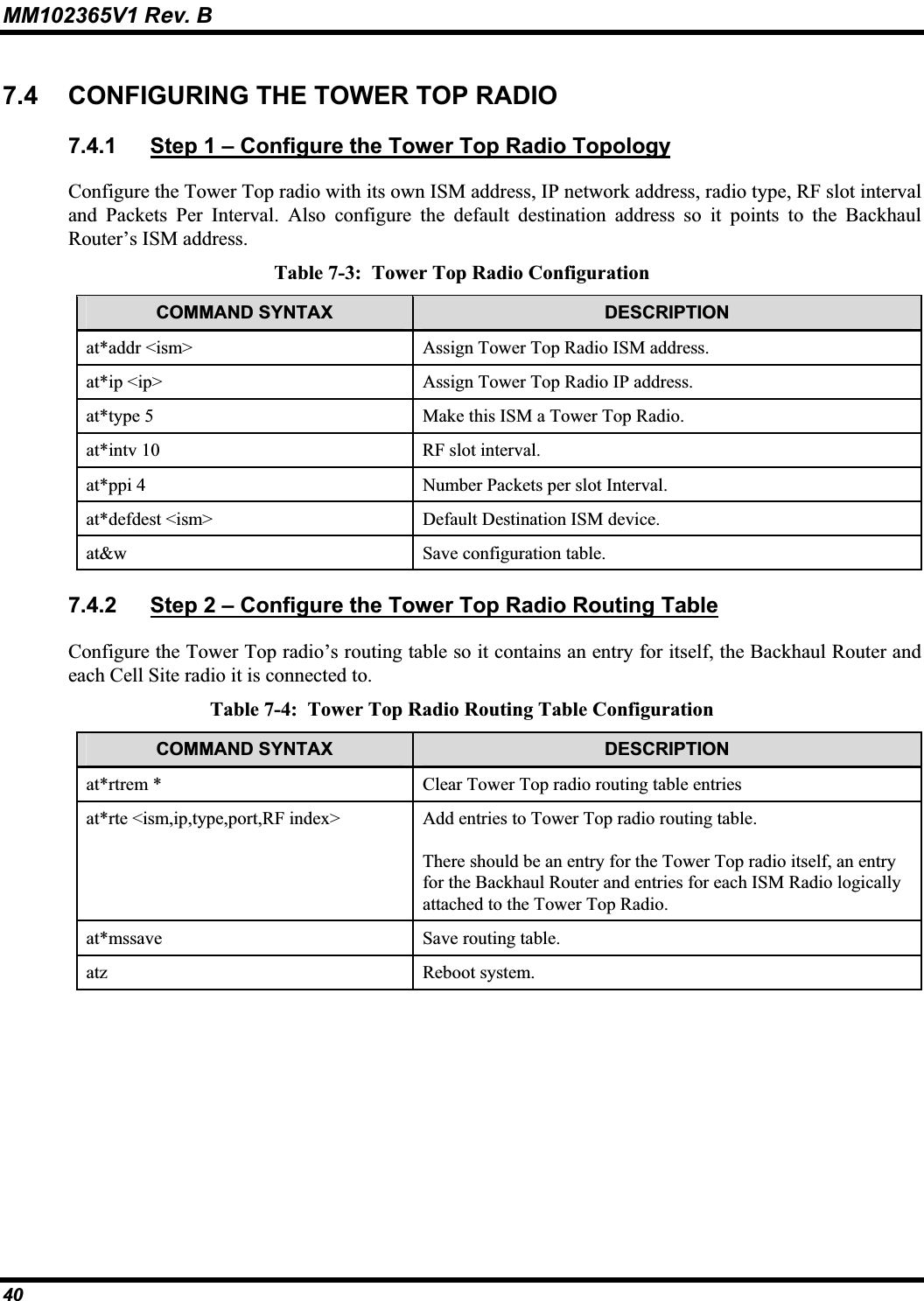
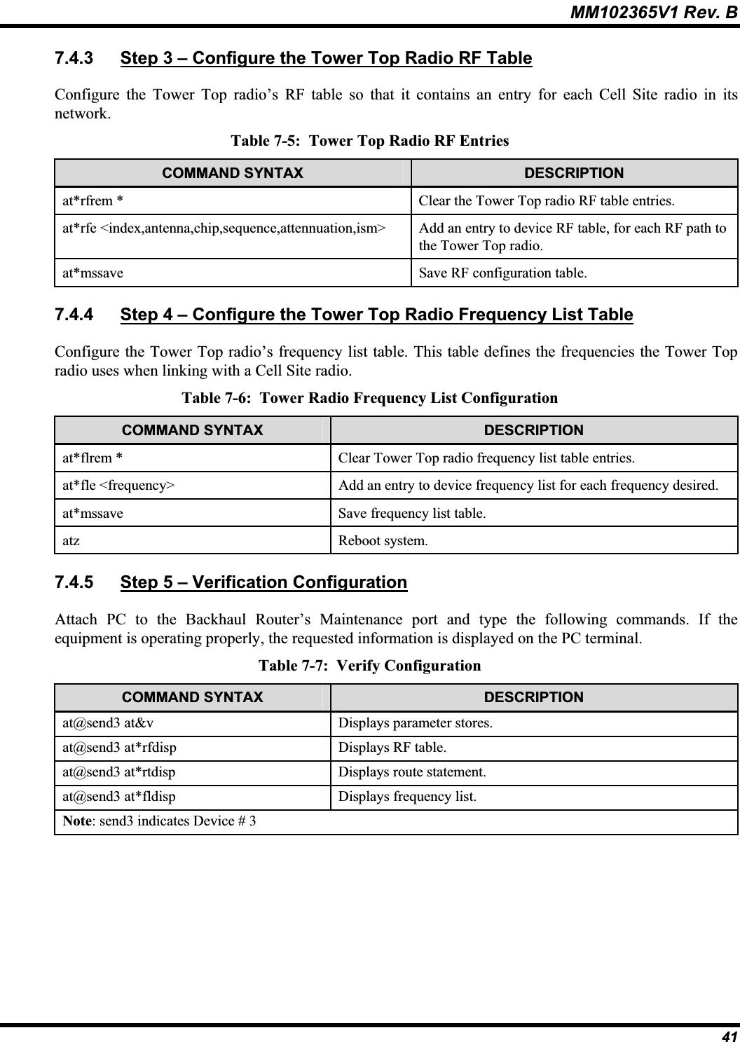
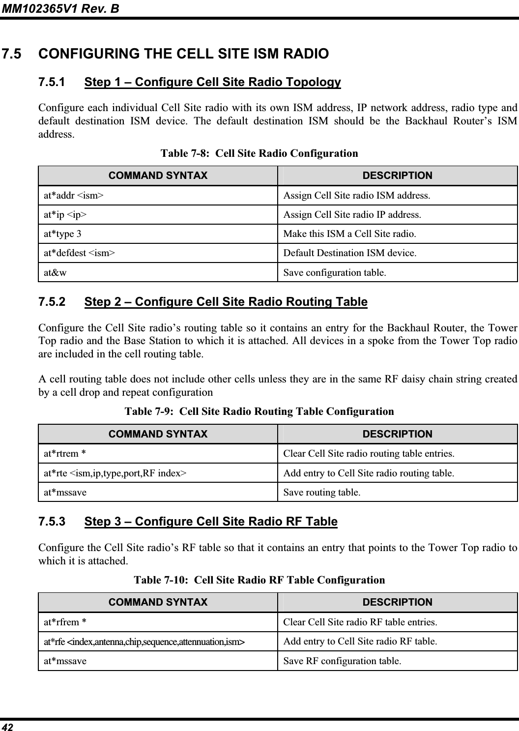
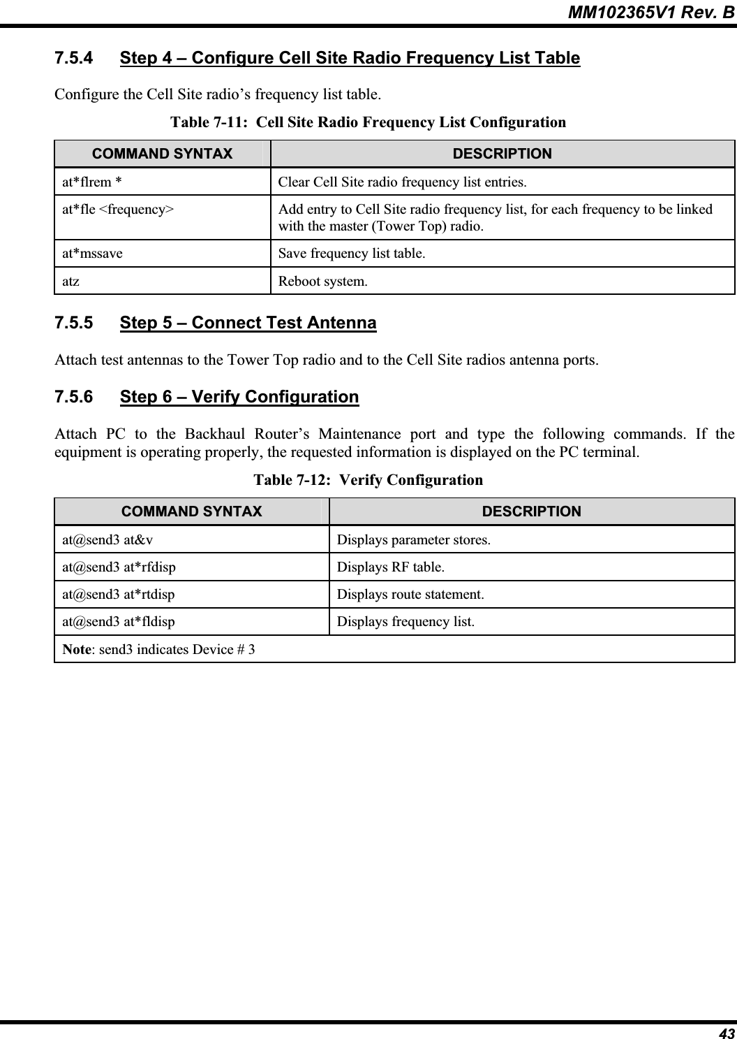
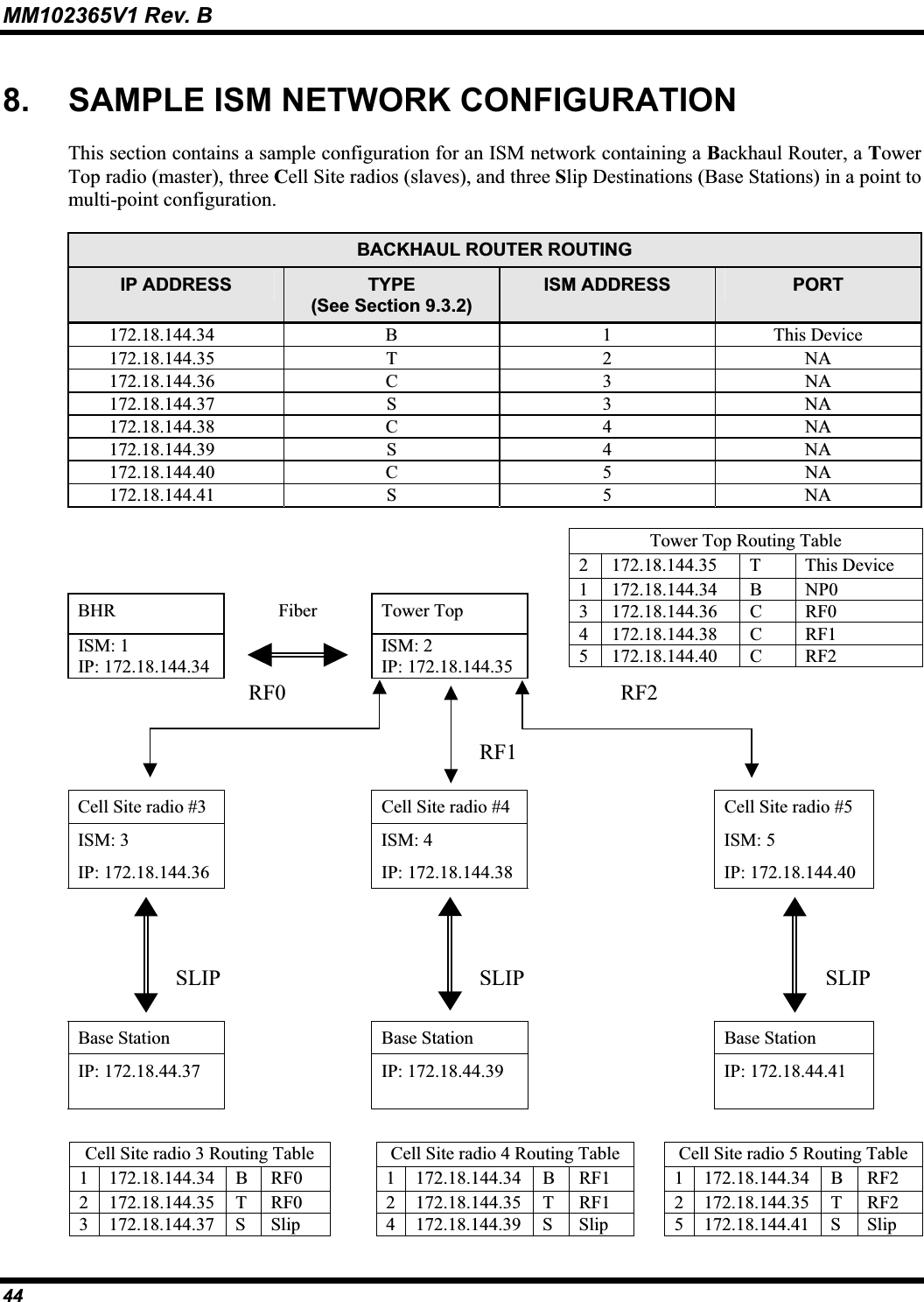
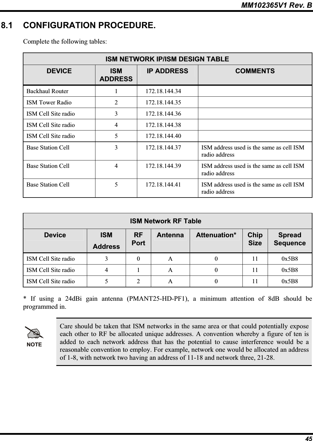
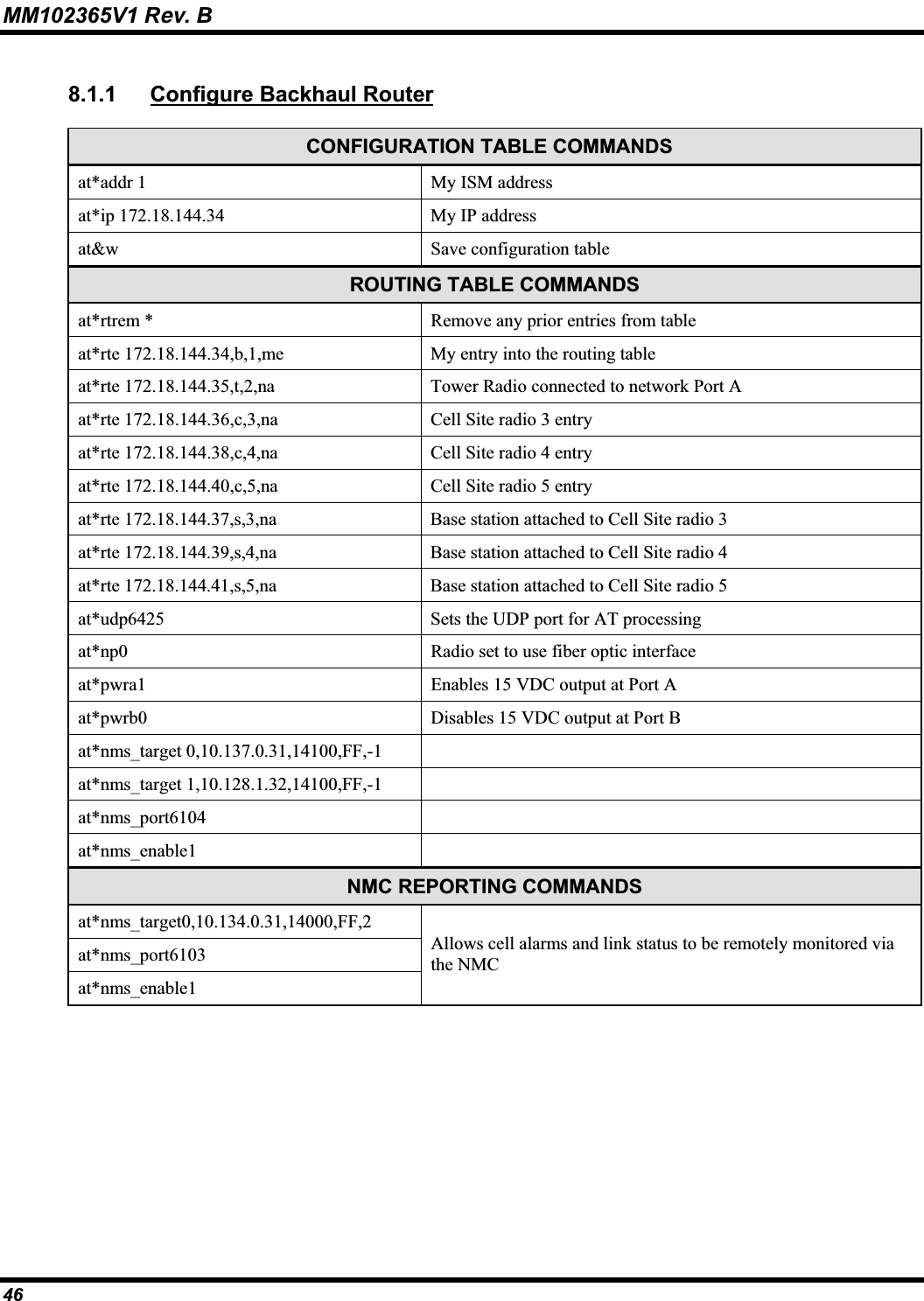
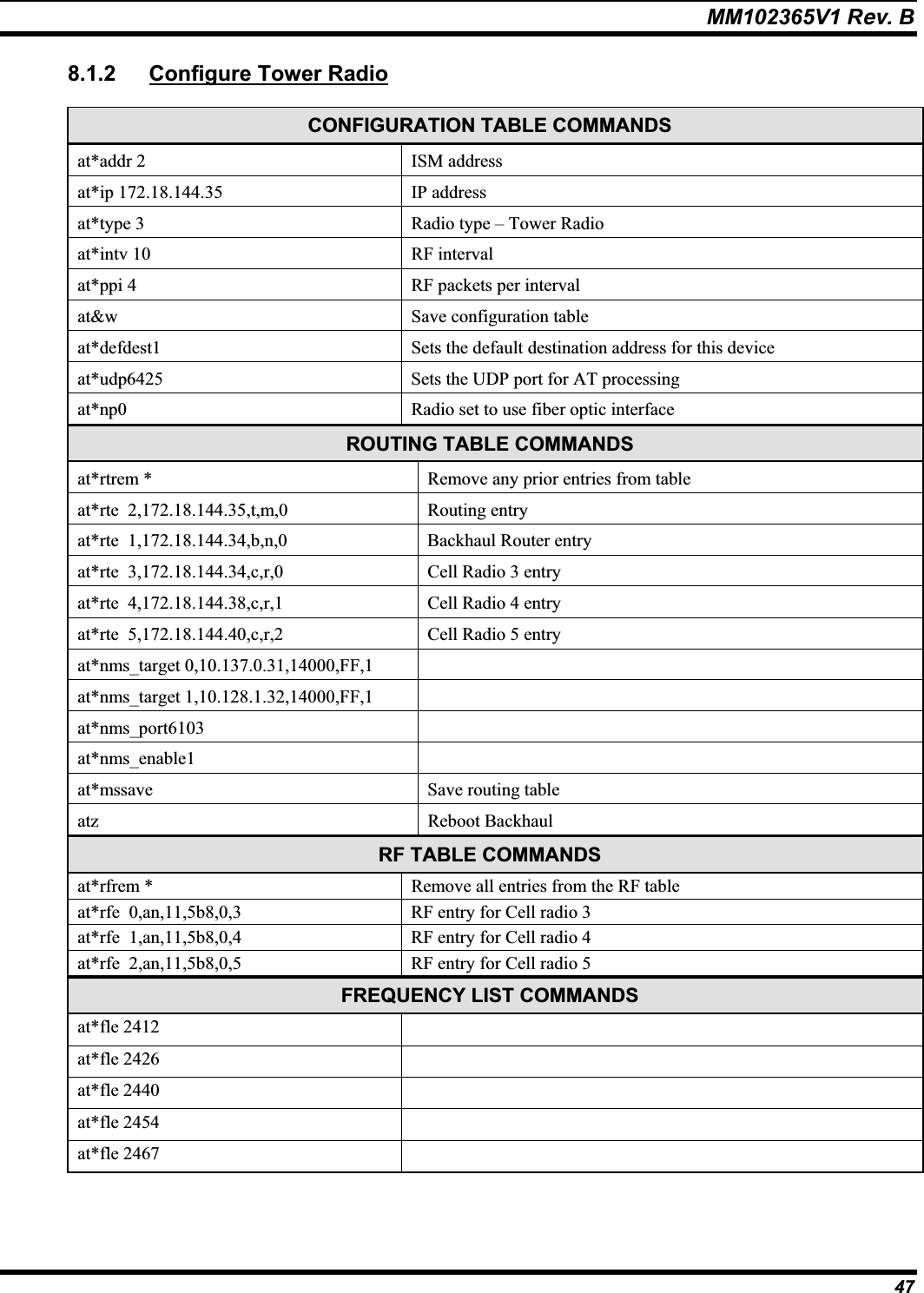
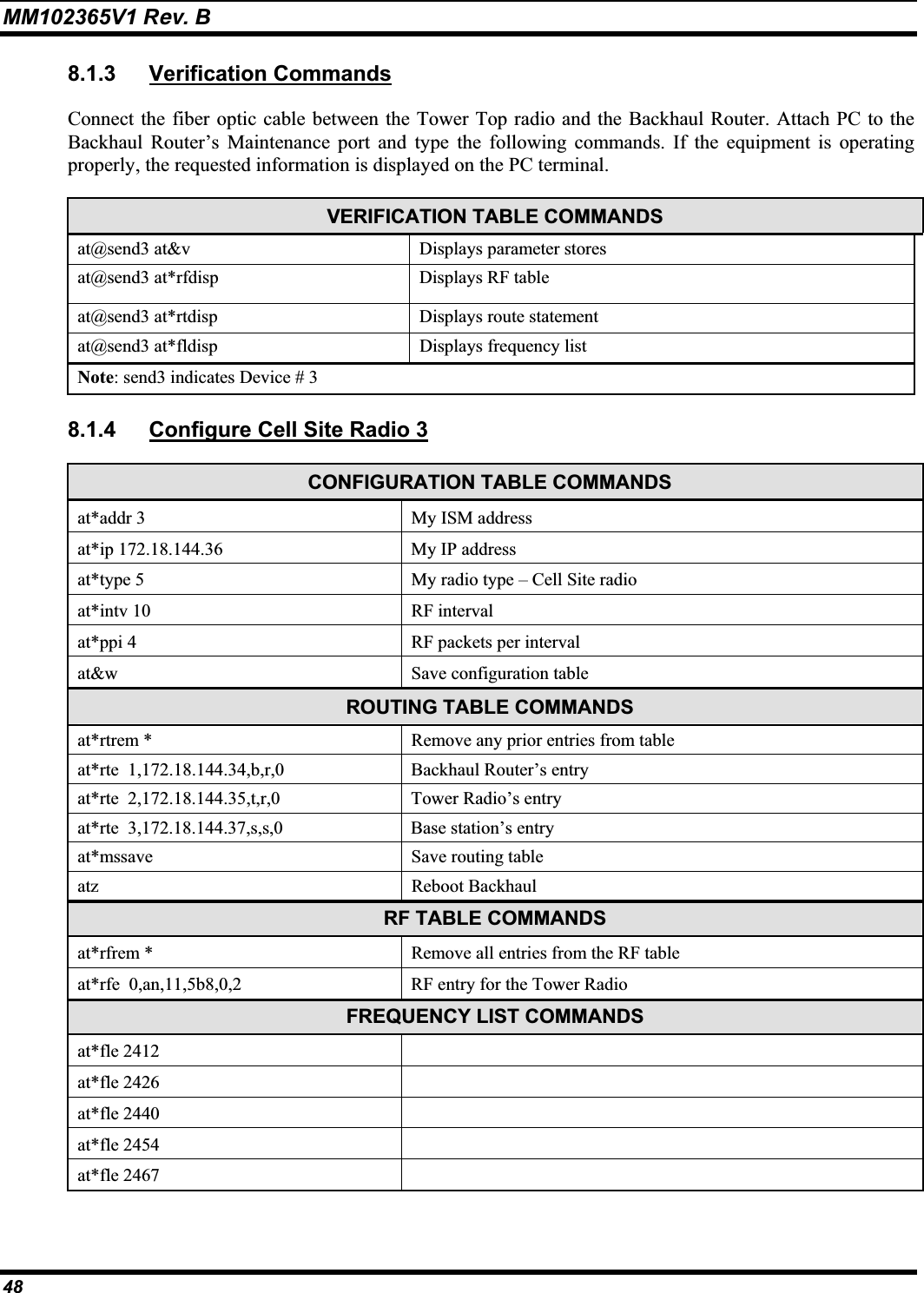
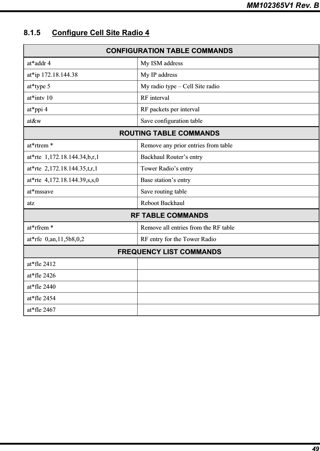
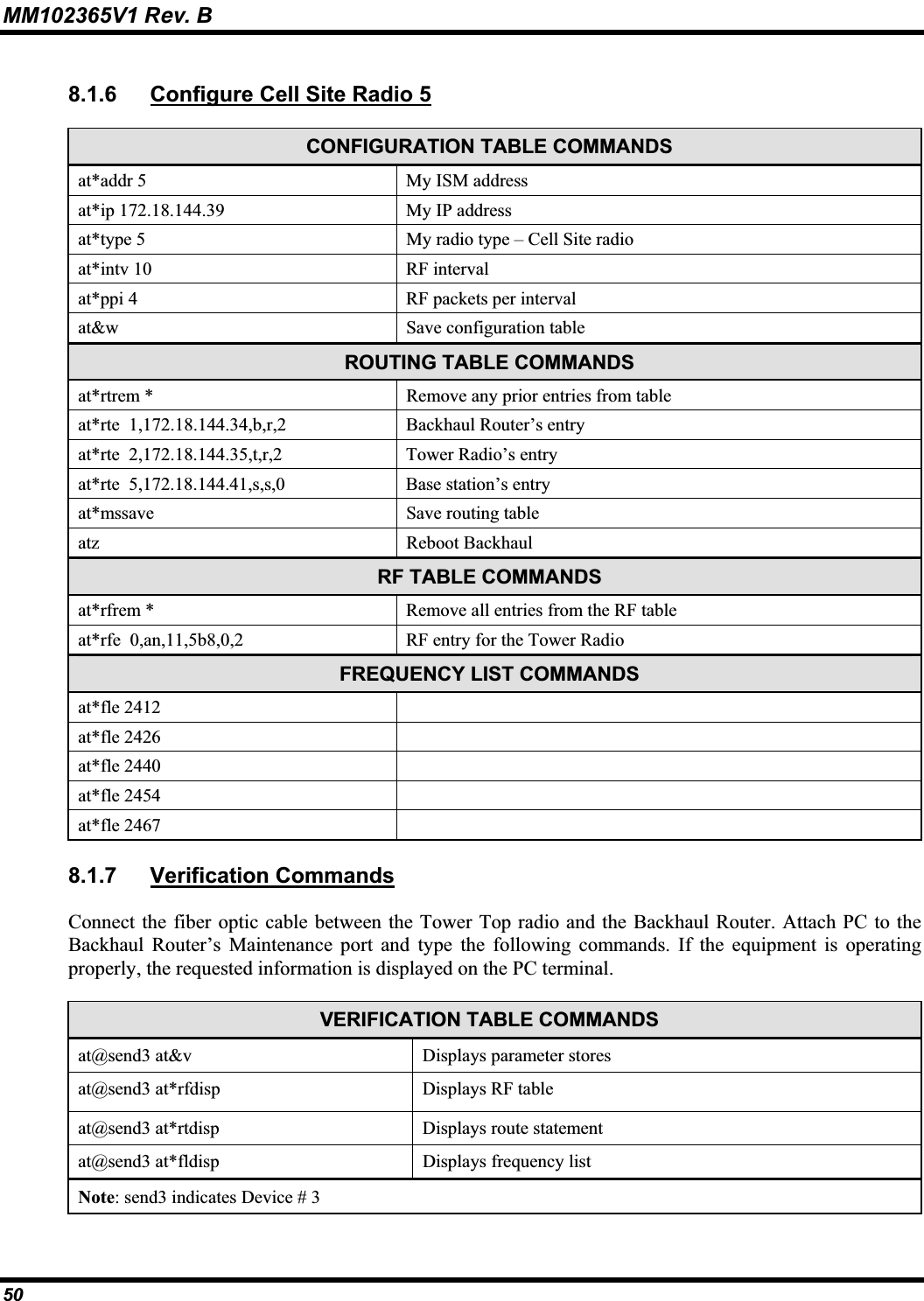
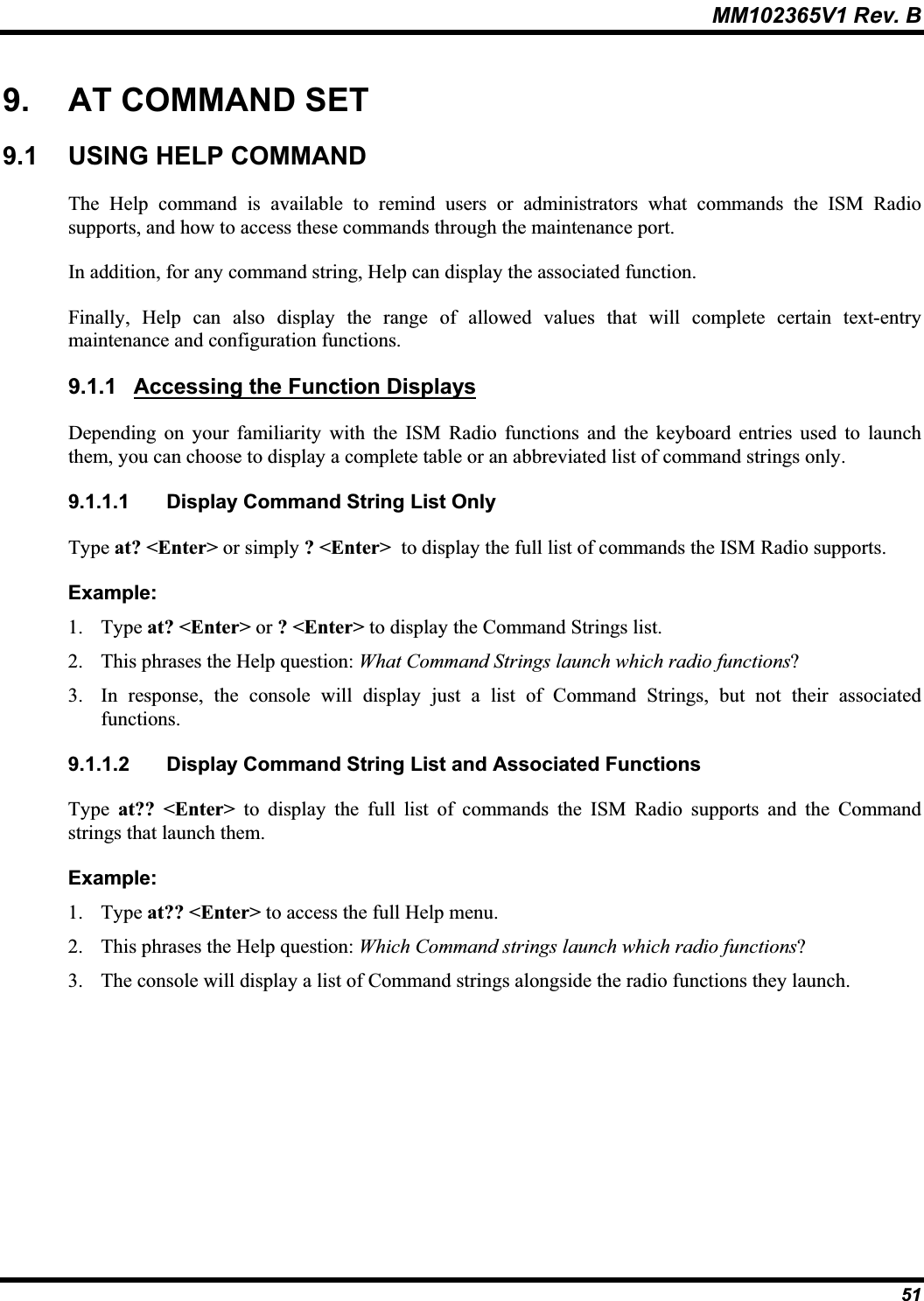
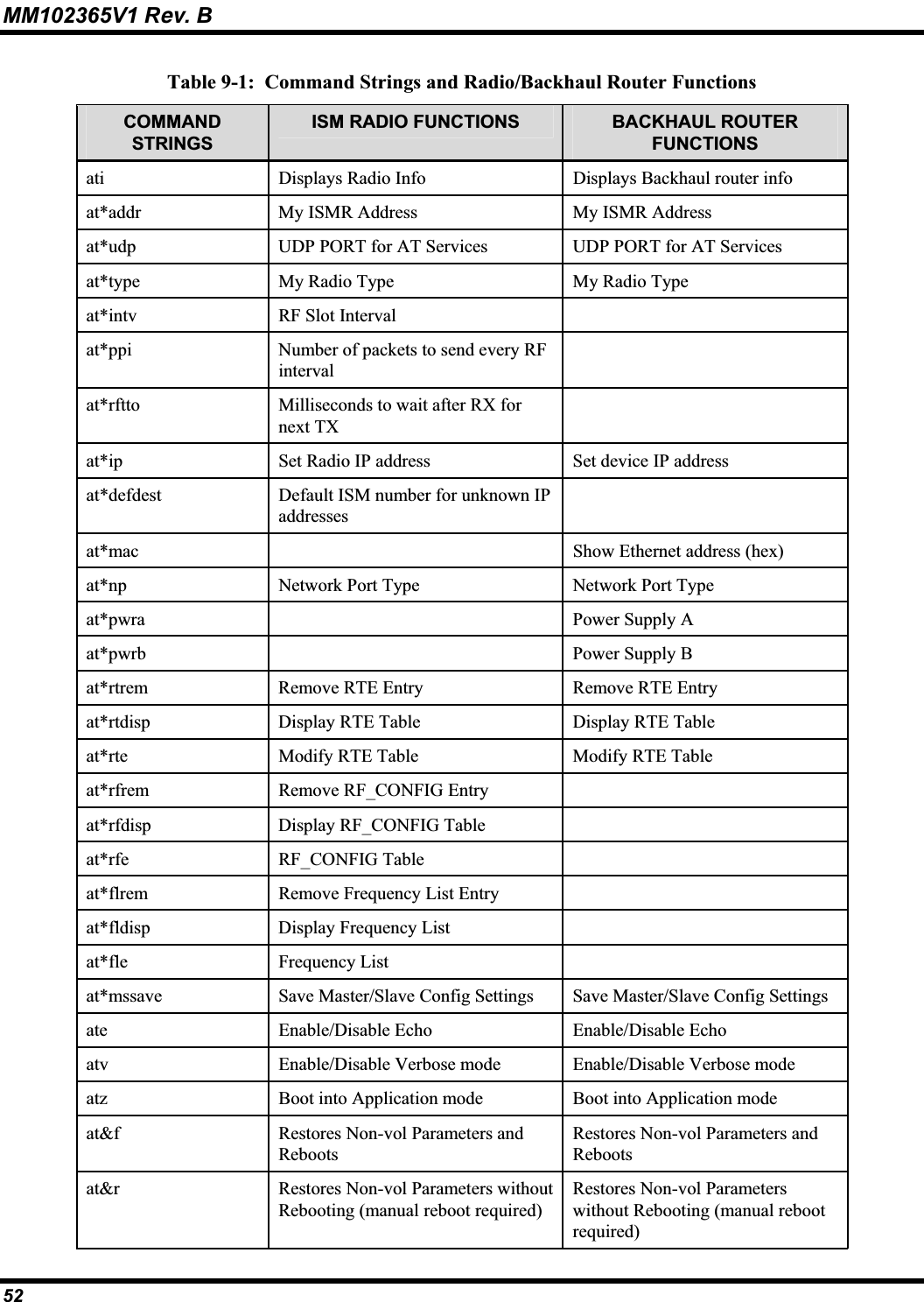
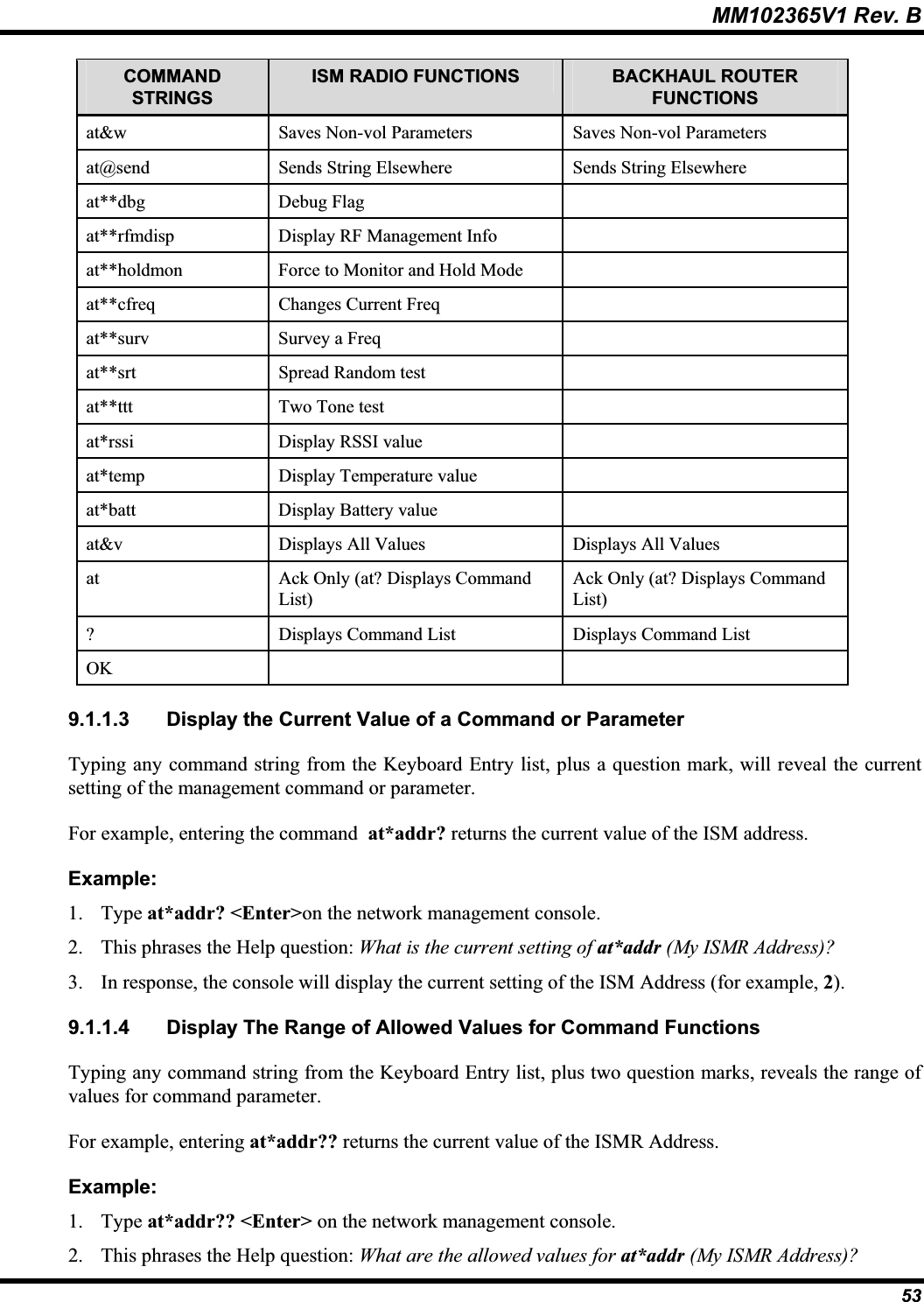
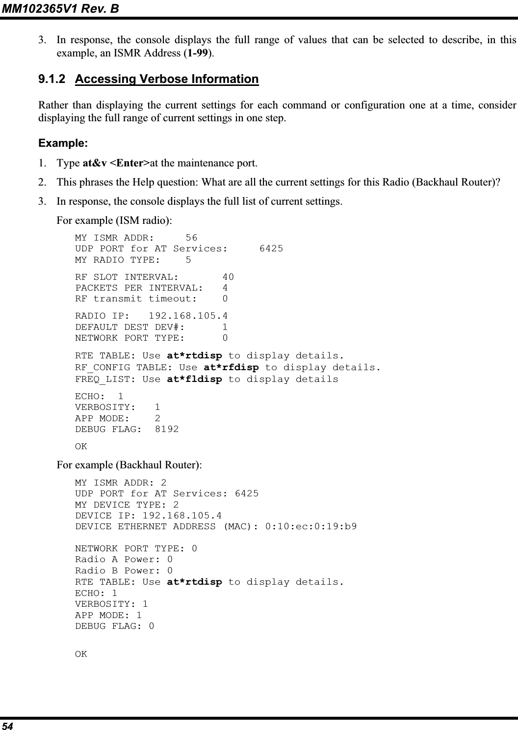
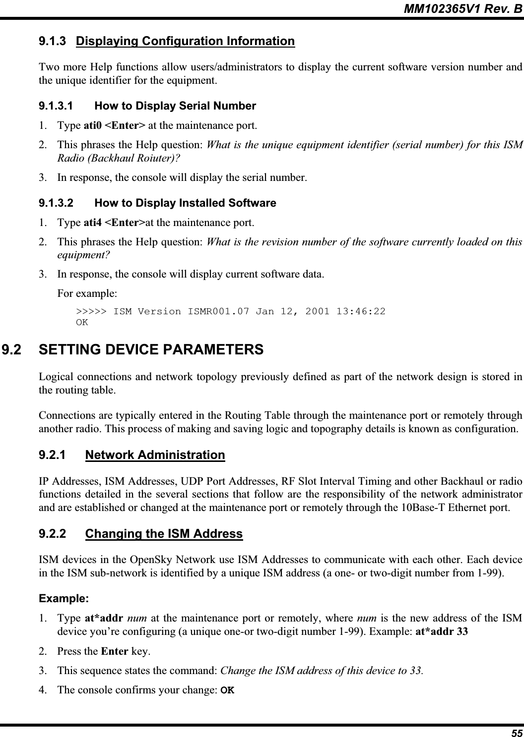
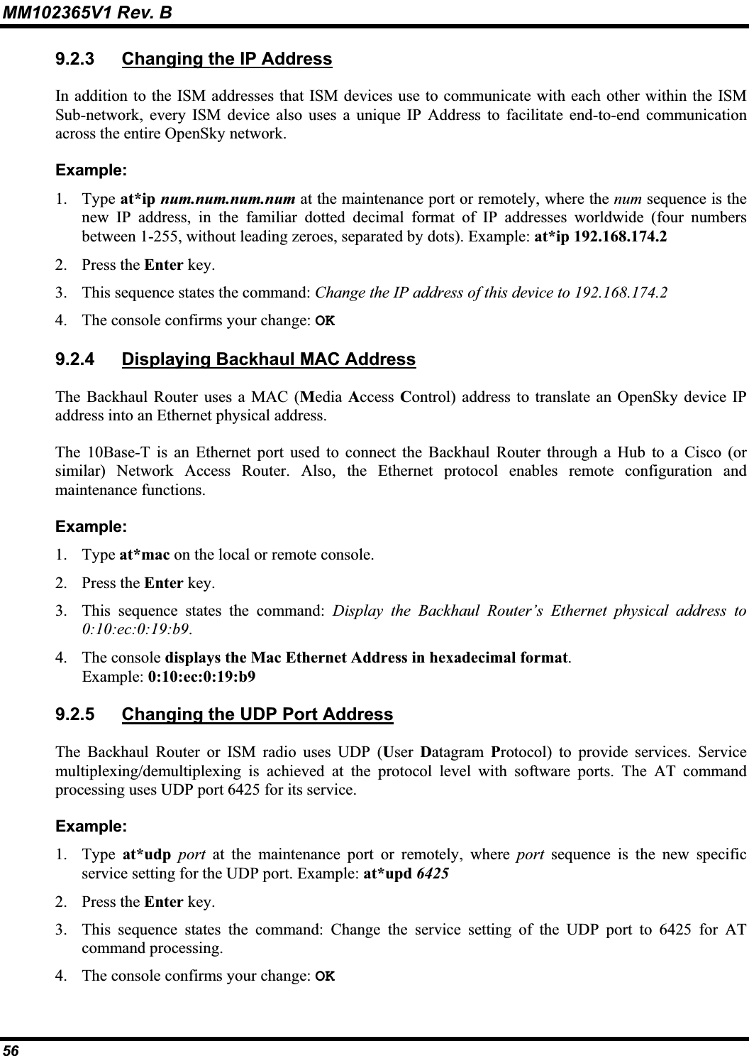
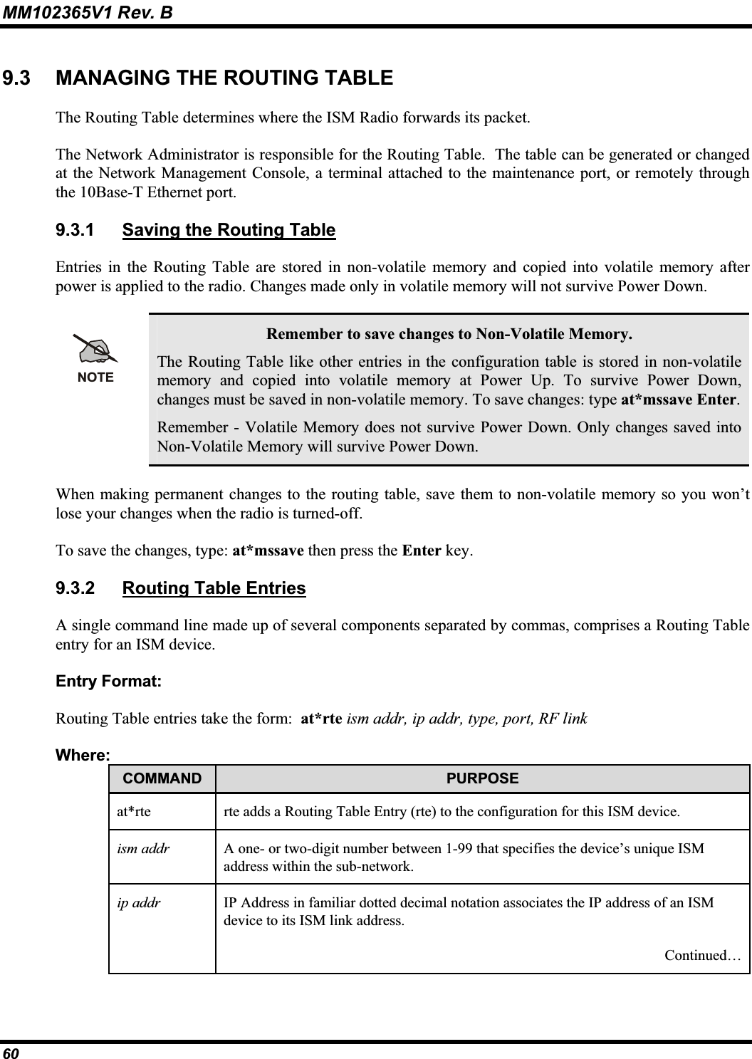
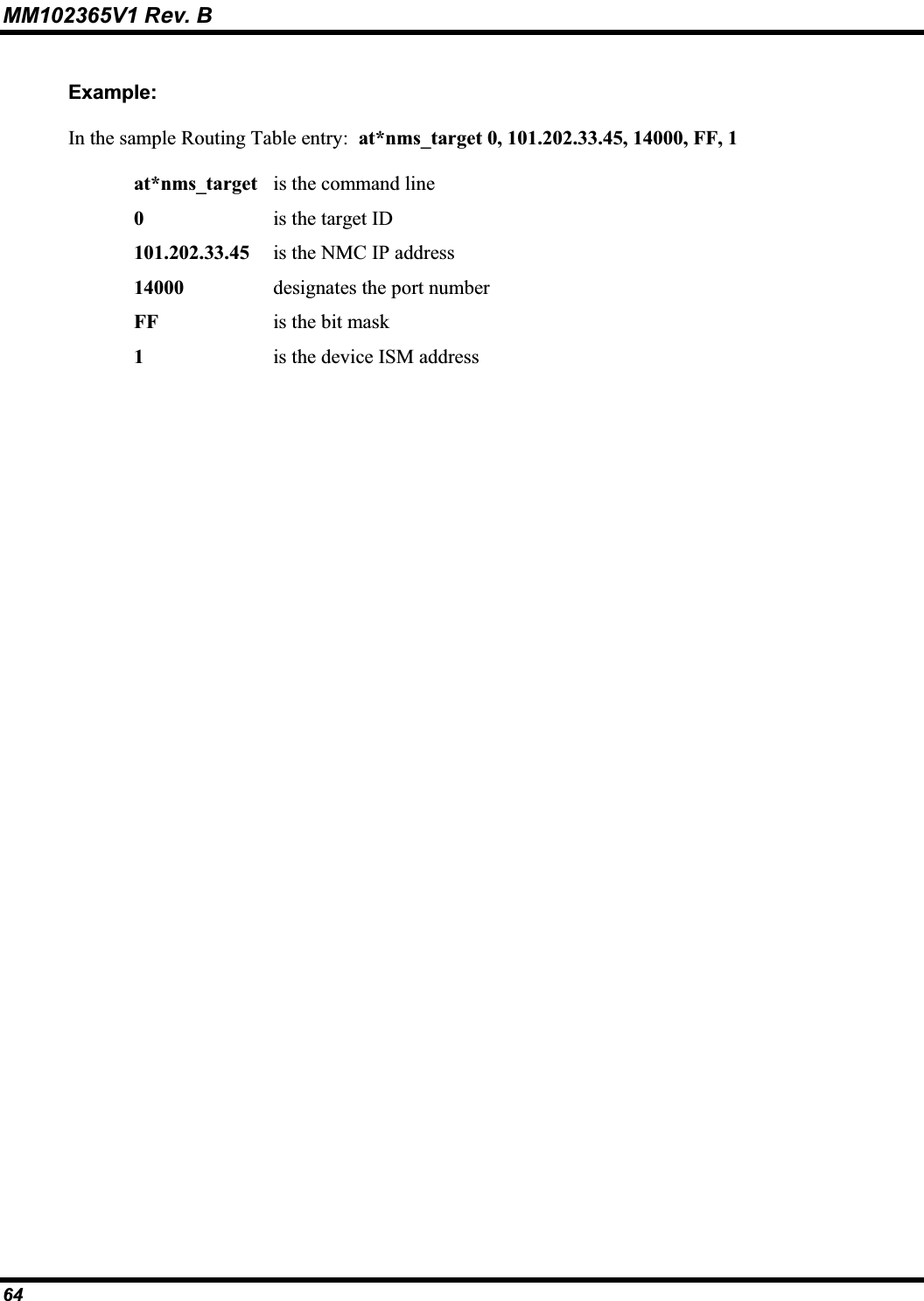
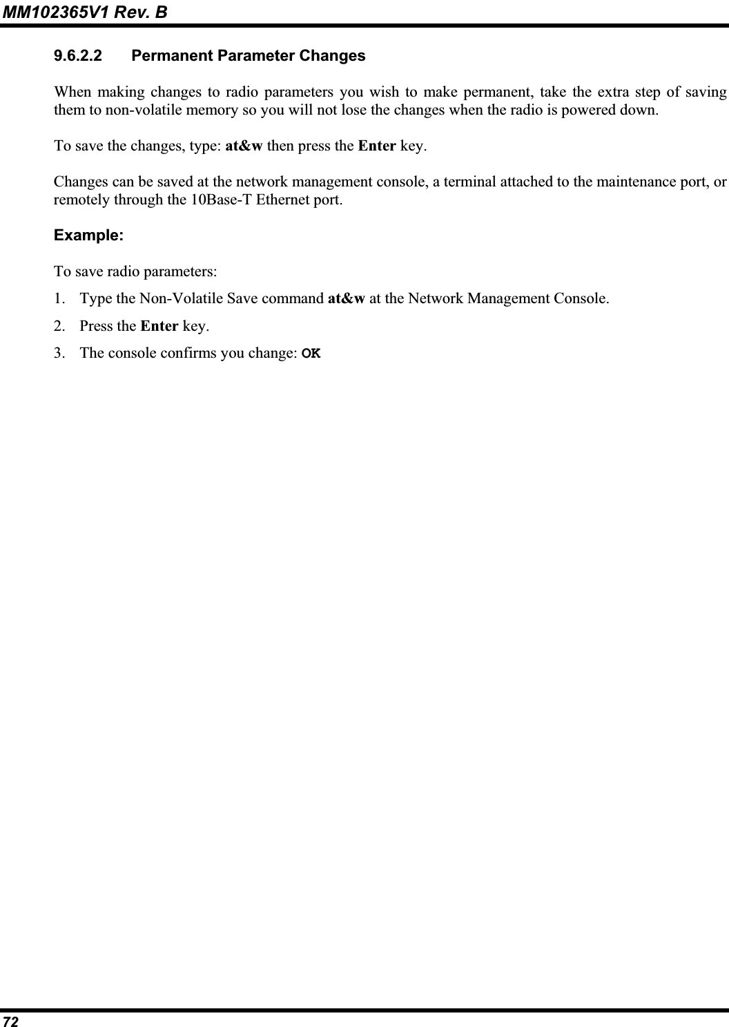
![MM102365V1 Rev. B 7.3 CONFIGURING THE BACKHAUL ROUTER The Backhaul Router can be remotely configured by using the at@send command from a local or remoteISM radio maintenance port.WARNINGIf remote changes are made to the Backhaul Router that impact link or route data, remoteconfiguration will no longer be available. A site visit to manually connect to the device may be necessary to restore the link. The at@send command is used to verify link connectivity among devices connected in the ISM network. 7.3.1 Step 1 – Configure Backhaul ISM and IP Network AddressesConfigure the Backhaul Router with its own ISM address and IP network address. Table 7-1: ISM and IP Network Addresses COMMAND SYNTAX DESCRIPTIONat*addr <ism> Assign Backhaul Router’s ISM address. at*ip <ip> Assign Backhaul Router’s IP address. at&w Save configuration table.7.3.2 Step 2 – Setup Backhaul Routing TableAdd the ISM radio devices that are present in the network to the Backhaul Router routing table. This includes the base stations that are attached to the Cell Site radios. Table 7-2: Backhaul Routing Table COMMAND SYNTAX DESCRIPTIONat*rtrem * Clear the Backhaul Router routing table entries.at*rte <ip,type,ism,port> Add entries to the Backhaul Router routing table for each ISM radio device present in the network, including Cell Base Stations.at*pwra*[1 | 0] Enables/Disable 15 VDC output at Port A. at*pwrb*[1 | 0] Enable/Disable 15 VDC output at Port B.at*mssave Save routing table.atz Reboot.39](https://usermanual.wiki/HARRIS/MTT-A025.Manual-revised/User-Guide-453834-Page-40.png)