HARRIS MTT-A025 ISM Radio User Manual ISM Radio Network Installation
Harris Corporation ISM Radio ISM Radio Network Installation
HARRIS >
Contents
- 1. Users Manual
- 2. Manual revised
Users Manual

Installation Manual
MM102365V1 R1A
SkyLink® ISM Radio Network
ISM Radio and Backhaul Router

MM102365V1 R1A
REVISION DATE REASON FOR CHANGE
R1A October 2003 Original Release
This manual and the hardware and software it describes are copyright © 2003 M/A-COM, Inc. All rights are
reserved under the copyright laws of the United States and Canada and other laws. Without limiting the rights
under copyright, no part of this document may be reproduced, stored in or introduced into a retrieval system, or
transmitted in any form or by any means (electronic, mechanical, photocopying, recording, or otherwise), or for
any purpose, without the express written permission of M/A-COM, Inc.
The contents of this manual are not intended to and do not constitute a warranty of any sort. M/A-COM, Inc and
Tyco Electronics specifically disclaim any implied warranties of merchantability or fitness for any particular
purpose resulting from this manual.
Information in this document is subject to change without notice. M/A-COM, Inc. reserves the right to revise and
make changes to this manual (and to the product and software) from time to time without obligation to notify any
person of, or to provide any person with, such revisions or changes.
M/A-COM, Inc. and/or Tyco Electronics may have patents, patent applications, trademarks, copyrights, or other
intellectual property rights covering subject matter in this document. Except as expressly provided in any written
license agreement from M/A-COM, the furnishing of this document does not give any license to these patents,
trademarks, copyrights, or other intellectual property.
Windows and Windows®95 are either registered trademarks or trademarks of Microsoft Corporation.
Notice of Copyright
Copyright ©2003 M/A-COM, Incorporated.
All rights reserved.
Notice of Trademark
The name M/A-COM, the OpenSky and Skylink product names, and the M/A-COM and OpenSky logos are all trademarks of M/A-COM,
Inc.
M/A-COM, Inc.
1011 Pawtucket Blvd.
Lowell, MA 01853
Phone: 978.442.4000
Printed in the United States of America.
2

MM102365V1 R1A
TABLE OF CONTENTS
Page
1. REGULATORY AND SAFETY INFORMATION......................................................................... 8
1.1 REGULATORY INFORMATION........................................................................................................... 8
1.2 SAFETY DURING INSTALLATION AND SERVICE.......................................................................... 9
1.3 SAFETY SYMBOLS.............................................................................................................................. 10
2. SPECIFICATIONS ......................................................................................................................... 11
2.1 ISM TOWER TOP RADIO .................................................................................................................... 11
2.1.1 Transmit........................................................................................................................................ 11
2.1.2 Receive ......................................................................................................................................... 11
2.1.3 Physical......................................................................................................................................... 12
2.1.4 Environmental .............................................................................................................................. 12
2.1.5 Power............................................................................................................................................ 12
2.2 BACKHAUL ROUTER.......................................................................................................................... 12
2.2.1 Interfaces ...................................................................................................................................... 12
2.2.2 Fiber Optic Interface..................................................................................................................... 12
2.2.3 Physical......................................................................................................................................... 13
2.2.4 Environmental .............................................................................................................................. 13
2.2.5 Power............................................................................................................................................ 13
3. INTRODUCTION ............................................................................................................................ 14
3.1 PRODUCT DESCRIPTION ................................................................................................................... 14
3.2 COMPONENTS...................................................................................................................................... 14
3.2.1 ISM Radio .................................................................................................................................... 14
3.2.2 Backhaul Router ........................................................................................................................... 14
3.3 SUB-SYSTEM COMMUNICATION LINKS........................................................................................ 15
3.4 RADIO OPERATING MODES: MASTER AND SLAVE.................................................................... 15
3.4.1 Master........................................................................................................................................... 15
3.4.2 Slave ............................................................................................................................................. 15
3.5 ISM NETWORK CONFIGURATION................................................................................................... 15
3.5.1 Networked Master/Slave .............................................................................................................. 16
3.5.2 Packet Path To The Tower Site.................................................................................................... 16
3.5.3 Packet Path to the Backhaul Router..............................................................................................16
3.5.4 Packet Path to the Cell Site ISM Radios....................................................................................... 17
3.6 OPENSKY APPLICATIONS................................................................................................................. 17
3.6.1 Standalone Repeater Operation .................................................................................................... 17
3.6.2 Cell-Drop-and-Repeat Operation ................................................................................................. 17
3.7 TECHNICAL ASSISTANCE................................................................................................................. 18
4. UNPACKING AND CHECKING EQUIPMENT ......................................................................... 19
4.1 UNPACKING EQUIPMENT ................................................................................................................. 19
4.2 INSPECTING AND INVENTORING EQUIPMENT ........................................................................... 19
3

MM102365V1 R1A
TABLE OF CONTENTS
Page
5. PRE-INSTALLATION CONSIDERATIONS............................................................................... 20
5.1 CHECKLIST...........................................................................................................................................20
5.2 BACKHAUL ROUTER INSTALLATION CHECKLIST.....................................................................20
5.3 PREPARATION FOR FIELD INSTALLATION...................................................................................21
5.4 SAFETY RECOMMENDATIONS.........................................................................................................21
5.5 HAZARD WARNINGS..........................................................................................................................21
5.6 ELECTROSTATIC DISCHARGE .........................................................................................................22
5.7 CABLING CONSIDERATIONS............................................................................................................22
5.7.1 Ethernet Connections....................................................................................................................22
5.7.2 ISM Radio Power/Fiber Optic Connections .................................................................................22
5.7.3 Maintenance Port Connection.......................................................................................................22
6. INSTALLATION.............................................................................................................................. 24
6.1 TOWER TOP ISM RADIO ENCLOSURE INSTALLATION .............................................................. 24
6.1.1 Power and Grounding Requirements............................................................................................24
6.1.2 Lightning Protection .....................................................................................................................24
6.1.3 ISM Radio Co-located with The Backhaul Router .......................................................................25
6.1.4 Connect Radio to Another ISM Device........................................................................................26
6.2 ANTENNA SYSTEM INSTALLATION............................................................................................... 26
6.2.1 Antenna Installation......................................................................................................................26
6.2.2 Antenna RF Cable Installation......................................................................................................27
6.2.3 Antenna System Testing ...............................................................................................................27
6.3 POWER/FIBER OPTIC CABLE INSTALLATION\.............................................................................28
6.3.1 Installing the Power/Fiber Optic Cable Assembly........................................................................29
6.4 BACKHAUL ROUTER INSTALLATION............................................................................................31
6.4.1 Front Panel Features .....................................................................................................................31
6.4.2 Rear Panel Features ......................................................................................................................32
6.4.3 Mounting The Backhaul Router....................................................................................................33
6.4.4 Power Cable Installation...............................................................................................................33
6.4.5 Ethernet Connection .....................................................................................................................34
6.4.6 Fiber Optic Connection.................................................................................................................34
6.5 MAINTENANCE AND TEST CONNECTIONS................................................................................... 35
6.5.1 Connecting an ISM Radio to PC or Terminal............................................................................... 35
6.5.2 Connecting Backhaul Router to a PC or Terminal........................................................................35
6.5.3 Maintenance Port Settings ............................................................................................................37
7. NETWORK CONFIGURATION ................................................................................................... 38
7.1 INTRODUCTION...................................................................................................................................38
7.2 ROUTING TABLES............................................................................................................................... 38
7.3 CONFIGURING THE BACKHAUL ROUTER.....................................................................................39
7.3.1 Step 1 – Configure Backhaul ISM and IP Network Addresses ....................................................39
7.3.2 Step 2 – Setup Backhaul Routing Table .......................................................................................39
7.4 CONFIGURING THE TOWER TOP RADIO........................................................................................40
7.4.1 Step 1 – Configure the Tower Top Radio Topology .................................................................... 40
4

MM102365V1 R1A
TABLE OF CONTENTS
Page
7.4.2 Step 2 – Configure the Tower Top Radio Routing Table............................................................. 40
7.4.3 Step 3 – Configure the Tower Top Radio RF Table..................................................................... 41
7.4.4 Step 4 – Configure the Tower Top Radio Frequency List Table.................................................. 41
7.4.5 Step 5 – Verification Configuration .............................................................................................41
7.5 CONFIGURING THE CELL SITE ISM RADIO................................................................................... 42
7.5.1 Step 1 – Configure Cell Site Radio Topology.............................................................................. 42
7.5.2 Step 2 – Configure Cell Site Radio Routing Table....................................................................... 42
7.5.3 Step 3 – Configure Cell Site Radio RF Table............................................................................... 42
7.5.4 Step 4 – Configure Cell Site Radio Frequency List...................................................................... 43
7.5.5 Step 5 – Connect Test Antenna .................................................................................................... 43
7.5.6 Step 6 – Verify Configuration ...................................................................................................... 43
8. SAMPLE ISM NETWORK CONFIGURATION......................................................................... 44
8.1 CONFIGURATION PROCEDURE. ...................................................................................................... 45
8.1.1 Configure Backhaul Router.......................................................................................................... 46
8.1.2 Configure Tower Radio................................................................................................................ 47
8.1.3 Verification Commands................................................................................................................ 48
8.1.4 Configure Cell Site Radio 3.......................................................................................................... 48
8.1.5 Configure Cell Site Radio 4.......................................................................................................... 49
8.1.6 Configure Cell Site radio 5........................................................................................................... 50
8.1.7 Verification Commands................................................................................................................ 50
9. AT COMMAND SET....................................................................................................................... 51
9.1 USING HELP COMMAND ................................................................................................................... 51
9.1.1 Accessing the Function Displays.................................................................................................. 51
9.1.2 Accessing Verbose Information ...................................................................................................53
9.1.3 Displaying Configuration Information......................................................................................... 54
9.2 SETTING DEVICE PARAMETERS ..................................................................................................... 55
9.2.1 Network Administration............................................................................................................... 55
9.2.2 Changing the ISM Address........................................................................................................... 55
9.2.3 Changing the IP Address.............................................................................................................. 55
9.2.4 Displaying Backhaul Mac Address .............................................................................................. 56
9.2.5 Changing the UDP Port Address.................................................................................................. 56
9.2.6 Changing Default ISM Destination .............................................................................................. 56
9.2.7 Changing RF Slot Interval Timer.................................................................................................57
9.2.8 Changing RF Packets per Interval................................................................................................57
9.2.9 Changing RF Transmit Delay....................................................................................................... 58
9.2.10 Changing Mode of Operation....................................................................................................... 58
9.2.11 Changing Network Port Assignment............................................................................................ 58
9.2.12 Enabling +15 VDC on Port A or B .............................................................................................. 59
9.3 MANAGING THE ROUTING TABLE................................................................................................. 60
9.3.1 Saving the Routing Table ............................................................................................................. 60
9.3.2 Routing Table Entries................................................................................................................... 60
9.3.3 Adding a Routing Table Entry...................................................................................................... 61
9.3.4 Removing a Routing Table Entry................................................................................................. 62
9.3.5 Displaying Routing Table Entries ................................................................................................62
9.3.6 NMS Trap Target Entries ............................................................................................................. 63
9.4 MANAGING THE RF CONFIGURATION TABLE ............................................................................ 65
9.4.1 Saving the RF Configuration Table.............................................................................................. 65
9.4.2 RF Configuration Table Entries ................................................................................................... 65
5

MM102365V1 R1A
TABLE OF CONTENTS
Page
9.4.3 Adding an RF Configuration Entry...............................................................................................67
9.4.4 Displaying RF Configuration Table Entries .................................................................................67
9.4.5 Removing an RF Configuration Table Entry................................................................................68
9.5 MANAGING THE FREQUENCY LIST TABLE..................................................................................69
9.5.1 Saving The Frequency List Table.................................................................................................69
9.5.2 Adding A Frequency List Entry....................................................................................................69
9.5.3 Displaying The Frequency List Table........................................................................................... 70
9.5.4 Removing a Frequency List Entry................................................................................................70
9.6 SAVING CONFIGURATION AND PARAMETER CHANGES..........................................................71
9.6.1 Saving Configuration Changes.....................................................................................................71
9.6.2 Saving Parameters Permanently....................................................................................................71
10. TROUBLESHOOTING................................................................................................................... 73
10.1 OVERVIEW............................................................................................................................................73
10.2 EQUIPMENT REQUIRED.....................................................................................................................73
10.3 REMOTE TROUBLESHOOTING......................................................................................................... 73
10.4 ON SITE TROUBLESHOOTING..........................................................................................................74
11. INSTALLATION CHECKSHEETS............................................................................................... 79
12. DIAGRAMS...................................................................................................................................... 81
12.1 APPLICATION DIAGRAMS.................................................................................................................81
TYPICAL CELL SITE ANTENNA SYSTEM WITH GROUNDING ..................................................81
TYPICAL CELL SITE ANTENNA ASSEMBLY .................................................................................82
TYPICAL ISM MASTER ANTENNA ASSEMBLY.............................................................................83
12.2 ASSEMBLY DIAGRAMS......................................................................................................................84
ISM RADIO IN MINI-CELL ENCLOSURE .........................................................................................84
ISM RADIO IN TTR ENCLOSURE ......................................................................................................85
AC POWERED BACKHAUL ROUTER ...............................................................................................86
DC POWERED BACKHAUL ROUTER ...............................................................................................87
12.3 INTERCONNECT DIAGRAMS ............................................................................................................88
ISM RADIO IN MINI_CELL ENCLOSURE.........................................................................................88
ISM RADIO IN RTT ENCLOSURE ......................................................................................................89
12.4 CABLE DIAGRAMS..............................................................................................................................90
POWER/FIBER OPTIC CABLE ............................................................................................................90
POWER/FIBER OPTIC CABLE ............................................................................................................91
6

MM102365V1 R1A
TABLE OF FIGURES
Page
FIGURE 3-1: TOWER AND CELL SITE ISM RADIOS .......................................................................................................... 16
FIGURE 3-2: ISM REPEATER CELL-CONFIGURATION SETUPS ......................................................................................... 17
FIGURE 6-1: ISM TOWER TOP RADIO ENCLOSURE ........................................................................................................ 25
FIGURE 6-2: FIBER CABLE MOUNTED IN TOWER TOP RADIO ENCLOSURE ..................................................................... 29
FIGURE 6-3: WIRING THE POWER/FIBER OPTIC CABLE ASSEMBLY................................................................................ 30
FIGURE 6-4: BACKHAUL ROUTER – FRONT PANEL.......................................................................................................... 31
FIGURE 6-5: BACKHAUL ROUTER – REAR PANEL (DC) .................................................................................................. 32
FIGURE 6-6: BACKHAUL ROUTER – OUTPUT CONNECTIONS ........................................................................................... 34
FIGURE 6-7: RS-232 CABLE FOR CONNECTING PC TO ISM RADIO................................................................................. 35
FIGURE 6-8: MAINTENANCE PORT (TEST) SERIAL I/O................................................................................................... 36
FIGURE 6-9: ISM RADIO I/O CONNECTORS..................................................................................................................... 36
TABLE OF TABLES
Page
TABLE 5-1: EIA/TIA-232 BAUD FOR DISTANCE RATES ................................................................................................ 23
TABLE 6-1: ISM ANTENNAS .......................................................................................................................................... 26
TABLE 6-2: ANTENNA RF CABLES................................................................................................................................. 27
TABLE 6-3: POWER/FIBER OPTIC CABLE ASSEMBLY LENGTHS...................................................................................... 28
TABLE 6-4: BACKHAUL ROUTER FRONT PANEL INDICATORS......................................................................................... 31
TABLE 6-5: RJ-45 TO DB-9 CONNECTIONS.................................................................................................................... 36
TABLE 7-1: ISM AND IP NETWORK ADDRESSES............................................................................................................ 39
TABLE 7-2: BACKHAUL ROUTING TABLE....................................................................................................................... 39
TABLE 7-3: TOWER TOP RADIO CONFIGURATION .......................................................................................................... 40
TABLE 7-4: TOWER TOP RADIO ROUTING TABLE CONFIGURATION ............................................................................... 40
TABLE 7-5: TOWER TOP RADIO RF ENTRIES ................................................................................................................. 41
TABLE 7-6: TOWER RADIO FREQUENCY LIST CONFIGURATION ..................................................................................... 41
TABLE 7-7: VERIFY CONFIGURATION............................................................................................................................. 41
TABLE 7-8: CELL SITE RADIO CONFIGURATION............................................................................................................. 42
TABLE 7-9: CELL SITE RADIO ROUTING TABLE CONFIGURATION.................................................................................. 42
TABLE 7-10: CELL SITE RADIO RF TABLE CONFIGURATION.......................................................................................... 42
TABLE 7-11: CELL SITE RADIO FREQUENCY LIST CONFIGURATION............................................................................... 43
TABLE 7-12: VERIFY CONFIGURATION........................................................................................................................... 43
TABLE 9-1: COMMAND STRINGS AND RADIO/BACKHAUL ROUTER FUNCTIONS............................................................. 51
7
MM102365V1 R1A
1. REGULATORY AND SAFETY INFORMATION
1.1 REGULATORY INFORMATION
These devices generate RF electromagnetic energy during transmit mode. They are
designed for and classified as “Occupational Use Only” meaning they must be used
only during the course of employment by individuals aware of the hazards and the
ways to minimize such hazards. These devices are NOT intended for use by the
“General Population” in an uncontrolled environment.
• This device complies with Part 15 of the Federal Communications Commission (FCC) Rules.
Operation is subject to the following two conditions: (1) this device may not cause harmful
interference; and (2) this device must accept any interference received, including interference that
may cause undesired operation.
• The FCC does not require the user to obtain a station license for this radio equipment before
operating it.
• This is a professionally installed device with a fixed power level. Only antennas listed on the grant
must be used. Shorter cable lengths or cable types with less gain must not be substituted as a
replacement other than those tested and listed in this manual.
• The operator is responsible at all times for the proper operation and maintenance of the equipment.
• No FCC license is required for personnel maintaining the equipment.
• FCC regulations state that the frequency, deviation, and power of a radio transmitter must be
maintained within specified limits. It is therefore recommended that the power level be checked
before the station is placed in service.
Use of this radio as described below will result in user exposure substantially below the FCC
recommended limits for human exposure to Radio Frequency Electromagnetic energy.
Before operating this radio:
• Do not operate this radio if any of the RF connectors are not secure or if open connections are not
properly terminated.
• Do not operate this radio near electrical blasting caps or in an explosive atmosphere.
NOTE
Changes or modifications not expressly approved could void the user's authority to
operate this equipment.
8

MM102365V1 R1A
NOTE
This equipment has been tested and found to comply with the limits for a Class B digital
device, pursuant to part 15 of the FCC Rules. These limits are designed to provide
reasonable protection against harmful interference in a residential installation. This
equipment generates, uses and can radiate radio frequency energy and, if not installed
and used in accordance with the instructions, may cause harmful interference to radio
communications. However, there is no guarantee that interference will not occur in a
particular installation. If this equipment does cause harmful interference to radio or
television reception, which can be determined by turning the equipment off and on, the
user is encouraged to try to correct the interference by one or more of the following
measures:
• Reorient or relocate the receiving antenna.
• Increase the separation between the equipment and receiver.
• Connect the equipment into an outlet on a circuit different from that to which the
receiver is connected.
• Consult the dealer or an experienced radio/TV technician for help.
1.2 SAFETY DURING INSTALLATION AND SERVICE
The radio and antennas must be installed by experienced installation professionals. During the installation
of directional antennas, the installer must not point the main beam of the antenna at locations occupied by
persons and must warn others to maintain a minimum distance of 4 meters from the antenna. Failure to
follow these instructions will void the product warranty and may expose the end user and others to
excessive Radio Frequency hazards. All antennas are intended to be installed outdoors and at distances
from personnel well beyond the minimum allowable distance.
Proper grounding is necessary, not only for correct functionality and maximum performance, but to
minimize damage that may occur from lightning strikes. The ISM radio includes lightning-protection
devices, but they are only effective if the connections are made as the design intended. Follow the
installation instructions to ensure a properly grounded unit.
The radio must be serviced and installed by qualified technicians only. Be sure that the radio is properly
grounded according to the installation instructions.
This equipment generates or uses radio frequency energy. Changes or modifications may cause harmful
interference unless the modifications are expressly approved in the instruction manual. The user could
lose the authority to operate this equipment if an unauthorized change or modification is made.
9
MM102365V1 R1A
1.3 SAFETY SYMBOLS
The following conventions are used throughout this manual to alert the user to general safety precautions
that must be observed during all phases of operation, service, and repair of this product. Failure to comply
with these precautions or with specific warnings elsewhere in this manual violates safety standards of
design, manufacture, and intended use of the product. M/A-COM, Inc. assumes no liability for the
customer's failure to comply with these standards.
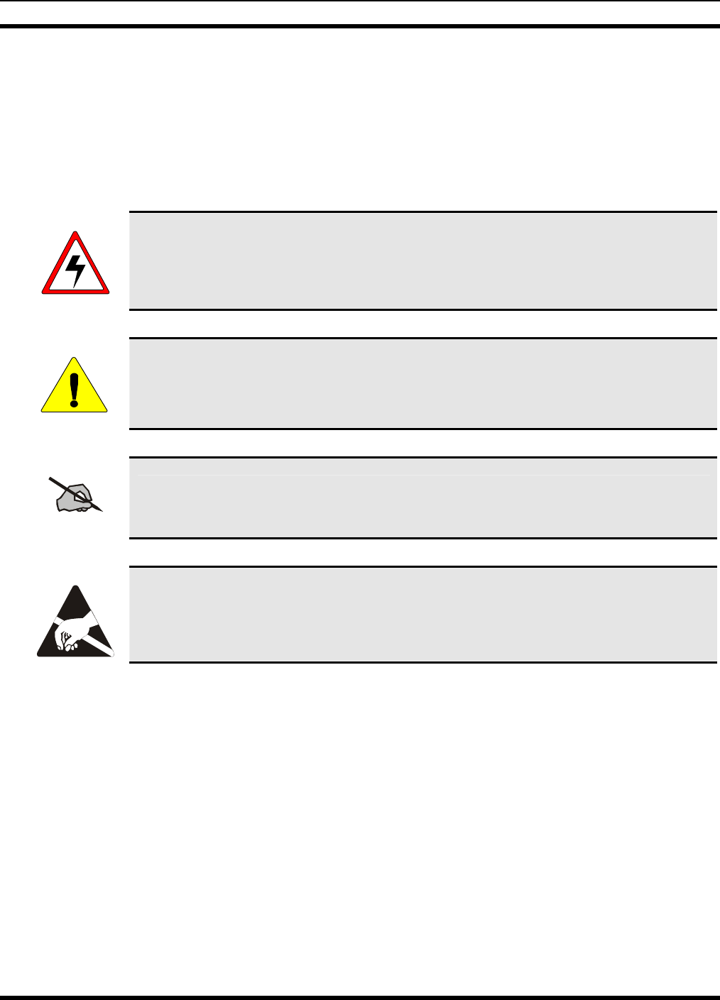
WARNING
The WARNING symbol calls attention to a procedure, practice, or the like, which, if not
correctly performed or adhered to, could result in personal injury. Do not proceed beyond a
WARNING symbol until the conditions identified are fully understood or met.
CAUTION
The CAUTION symbol calls attention to an operating procedure, practice, or the like,
which, if not performed correctly or adhered to, could result in damage to the equipment or
severely degrade the equipment performance.
NOTE
The NOTE symbol calls attention to supplemental information, which may improve
system performance or clarify a process or procedure.
The ESD symbol calls attention to procedures, practices, or the like, which could expose
equipment to the effects of Electro-Static Discharge. Proper precautions must be taken to
prevent ESD when handling circuit modules.
10

MM102365V1 R1A
2. SPECIFICATIONS
1
2.1 ISM TOWER TOP RADIO
2.1.1 Transmit
Frequency Range 2400-2480 MHz
First Transmit Frequency 2412 MHz
Last Transmit Frequency 2468 MHz
Modulation DBPSK
Spreading Modulation Direct Sequence Spread Spectrum
Sequence Length 11-15 chips, Software Configurable
Tuning Step Size 1.0 MHz
Frequency Control PLL Synthesizer
RF output Impedance 50 Ohms
Power Output -4 dBm to 28 dBm (630 mw) in 1 dB steps
Transmitter Duty Cycle 50%
Spurious & Harmonic Emissions Meets FCC requirements CFR47 Part 15
2.1.2 Receive
Frequency Range 2400-2480 MHz
First Receive Frequency 2412 MHz
Last Receive Frequency 2468 MHz
Tuning Step Size 1.0 MHz
Frequency Control PLL Synthesizer
Operation Center Operation Center
Sensitivity -90 dBm for 10-5 Bit Error Rate AWGN
Adjacent Channel Rejection 25 dB
Intermodulation 42 dB
1 These specifications are intended primarily for the use by the service technician. Refer to the appropriate Specifications
Sheet for the complete specifications.
11

MM102365V1 R1A
2.1.3 Physical
Height x Width x Depth 16 x 12 x 8 in. (40.5 x 30.5 x 20.5 cm)
Weight 17 lbs (including environmental enclosure)
2.1.4 Environmental
Operating -30°C to 60°C to 15,000 ft Altitude
Non-operating -40°C to 70°C to 30,000 ft Altitude
Humidity 5% to 95% Relative Humidity at 50°C
2.1.5 Power
DC Power +12 to +16 VDC
Power Dissipation 12 Watts max
2.2 BACKHAUL ROUTER
2.2.1 Interfaces
Ethernet Interface IEEE 802.3 10Base-T (10 Mbit/s)
RS-422 Interface 9-pin D-type Connector
Maintenance Port EIA/TIA-232asynchronous Serial Interface at
19.2K baud. Uses RJ-45 Connector
2.2.2 Fiber Optic Interface
Connector Type ST
Wavelength 820 nm Nominal
Fiber Type 62.5/125 µm Multimode
Transmit Power Level -15 dBm peak @ 25° C, with 1 meter cable length
Receiver Sensitivity -26dBm @ 25° C with 1 meter cable length
Bit Rate 1.25 Mbit/s
Coding Manchester
12

MM102365V1 R1A
2.2.3 Physical
Height (2 rack units) 3.50 in. (8.9 cm)
Width Standard 19 in. rack (48.3 cm)
Depth 14 in. (35.6 cm)
Weight 13 lbs
2.2.4 Environmental
Operating 0 °C to 60 °C to 15,000 ft altitude
Non-operating -20 °C to 70 °C to 30,000 ft altitude
Humidity 5% to 90% relative humidity non-condensing
2.2.5 Power
Voltage (DC) Nominal -48 VDC
Voltage (AC) Nominal 110 VAC (optional)
Power 50 Watts maximum
13

MM102365V1 R1A
3. INTRODUCTION
This manual describes how to install an ISM Radio Network consisting of the ISM Tower Top Radio and
the optional Backhaul Router. Because each installation is unique, this manual is designed only as a guide
for installing these products.
3.1 PRODUCT DESCRIPTION
The ISM Radio System extends the reach and signal strength of the overall OpenSky® network and
provides essential connectivity to ISM devices.
The ISM Network provides:
• Extended reach without high profile towers.
• Point-to-multipoint connectivity to extend the coverage area.
• Low-latency links with minimal impact on OpenSky network performance.
• Serial Line Internet Protocol (SLIP) and Internet Protocol (IP) packet processing.
Data and voice network controllers for the OpenSky network are located at the Operation Center. From
the Operation Center, voice and data packets are routed:
• Locally to other ISM devices.
• To another Operation Center.
• Through Interoperability Gateways to non-OpenSky networks.
Each tower site can be equipped with an ISM radio for one-hop communication directly to cell sites. In
addition, to enable the radio to function as a repeater where a link between a cell site and a tower site
cannot be made with a single hop, an additional ISM radio can be connected via fiber to an existing link.
For additionally supported configurations, refer to the ISM Radio Network Design Guide.
Cell sites are an extension of a tower site’s network of OpenSky Base Stations.
3.2 COMPONENTS
3.2.1 ISM Radio
The Tower Top ISM radio communicates with an ISM radio operating at each cell site. The Cell Site ISM
radio provides an interface to the OpenSky Base Station co-located at the cell site.
3.2.2 Backhaul Router
The Backhaul Router performs the protocol processing and enables an ISM radio to communicate to an
industry standard Network Access Router using an Ethernet 10base-T connection.
14

MM102365V1 R1A
The Network Access Router connection (a T1 Point-to-Point microwave link) terminates at the Operation
Center.
3.3 SUB-SYSTEM COMMUNICATION LINKS
The ISM radio is a Direct Sequence Spread Spectrum (DSSS) radio compliant with the FCC Part 15.247
regulations. It operates in the unlicensed ISM frequency band available for public use, between 2.400-
2.4835 GHz.
The radio operates as a subsystem within the OpenSky network to provide point-to-multipoint
communication links between tower sites and cell sites.
The ISM link extends a tower site’s coverage area beyond the devices it can reach directly. Areas poorly
served by high profile tower sites due to budgetary constraints, remote location or topographical
challenges can be affordably and reliably served from a cell site with optional ISM repeater site(s) in an
ISM subsystem.
3.4 RADIO OPERATING MODES: MASTER AND SLAVE
The ISM radio can be configured to operate in either of two modes: Master or Slave.
3.4.1 Master
A radio in Master mode controls the RF communications path of up to six radios configured in Slave
mode. A Master operating in Time Division Multiplexed (TDM) order initiates all RF communications.
In short, the Master radio addresses all associated Slave radios in round-robin fashion, giving each in turn
the opportunity to transmit or receive ISM addressed voice and data packets.
3.4.2 Slave
A radio in Slave mode transmits and receives segmented IP packets encapsulated with ISM headers only
when addressed by its associated ISM Master radio. The Slave radio buffers data received from its SLIP
(or fiber optic) interface until granted the time slot to transmit to its respective Master. A Slave radio has a
maximum amount of data that is transmitted in any given time slot provided by the Master.
NOTE
It should be noted that an ISM Master radio is also capable of communicating with
another ISM Master radio depending on the system design.
3.5 ISM NETWORK CONFIGURATION
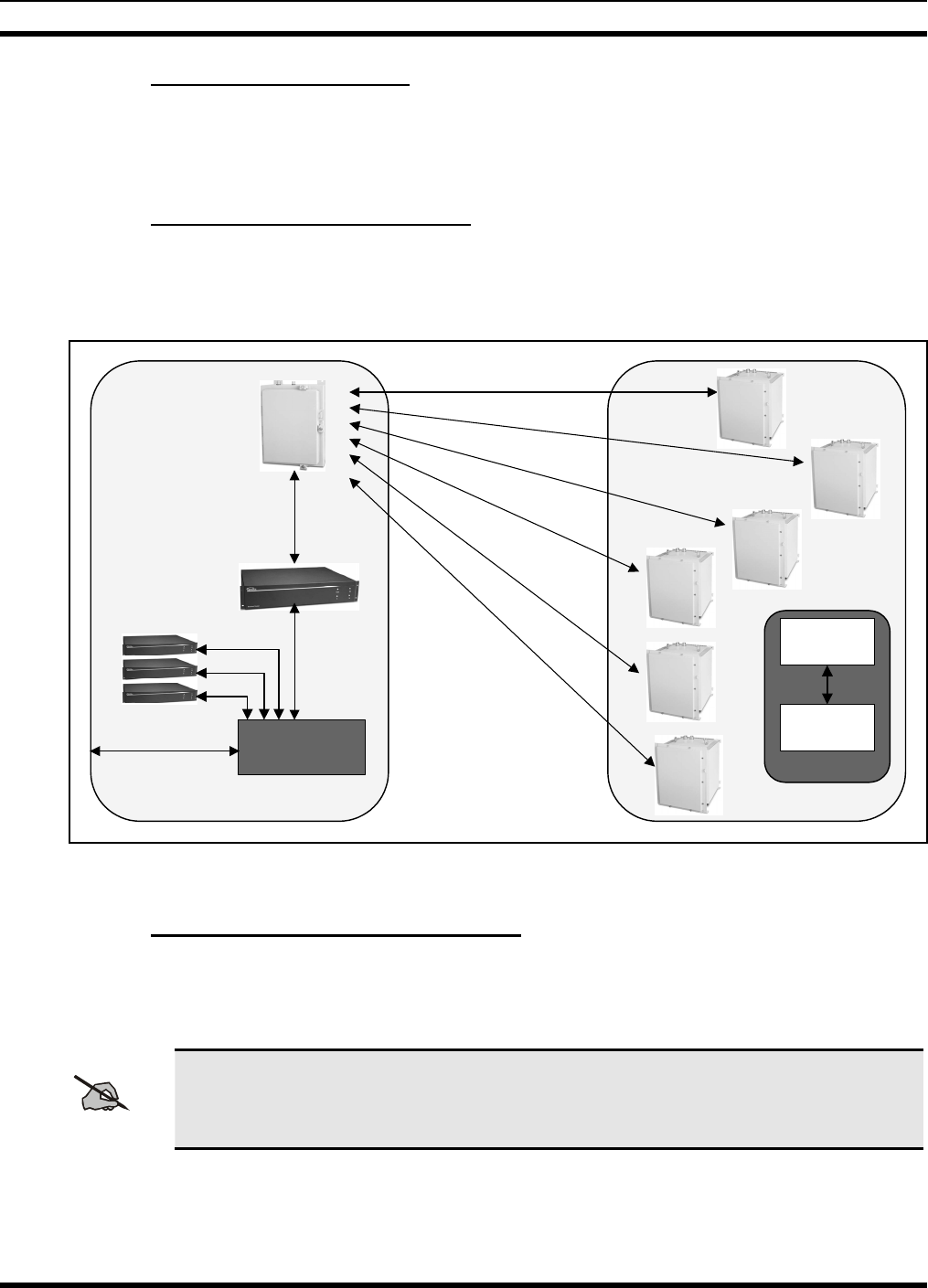
Figure 3-1 shows an ISM Tower Top radio supporting six cell site ISM radios. In this configuration, the
tower site is equipped with several DCX Base Station Units and a Backhaul Router with a single Master
ISM radio acting as a hub.
15
MM102365V1 R1A
3.5.1 Networked Master/Slave
The Master radio communicates with up to six Cell Site (or repeater, or Slave) radios. Each operates at
2.4 GHz and burst transfers the data using a 1 Mbps half duplex air link. The Master radio manages a
Time Division Duplex (TDD) protocol to service each Slave.
3.5.2 Packet Path To The Tower Site
The tower site functions as a relay. IP packets destined for a cell site OpenSky Base Station are routed to
the appropriate tower site using the T1 Point-to-Point Microwave link in a manner identical to packets
destined for OpenSky DCX Base Stations at that tower site.
ISM
Master
Backhaul
Router
Network
Port
10BaseT
Intranet
Tower Site
DCX
Cell Site 1
Cell Site 3
Cell Sites
ISM Radio
(Slave)
OpenSky
Base Station
Cell
SLIP
Network
Access Router
Cell
Site
2
Cell
Site
3
Cell
Site
1
Cell
Site
4
Cell
Site
5
Cell
Site
6
Figure 3-1: Tower and Cell Site ISM Radios
3.5.3 Packet Path to the Backhaul Router
The Network Access Router at the tower site routes ISM IP streams to the Backhaul Router for protocol
conversion and forwarding to the Master radio via the ISM network interface port.
NOTE
The Network Access Router is a component that includes a Cisco 3600 or other Ethernet
10Base-T Router.
16
MM102365V1 R1A
3.5.4 Packet Path to the Cell Site ISM Radios
The Master radio, in turn, routes the IP packets to the appropriate Slave radio. The Slave radio then passes
the IP stream to the associated OpenSky Base Station unit co-located at the cell site via an EIA-232 SLIP
interface.
The TDM system has the capacity to deliver bi-directional SLIP data at 38.4 Kbps to each Slave radio.
3.6 OPENSKY APPLICATIONS
Depending on network configuration requirements, ISM radios can operate as Standalone Repeaters or as
part of a Cell-Drop-and-Repeat setup.
3.6.1 Standalone Repeater Operation
• Two radios are used in a Repeater configuration, whether in Repeater or Cell-Drop-and-Repeat.
• Regardless of the setup, radios are always configured in Master/Slave combinations.
• A Master radio (whether at a primary tower site, repeater site or Cell-Drop-and-Repeat) can always be
configured as a multipoint radio.
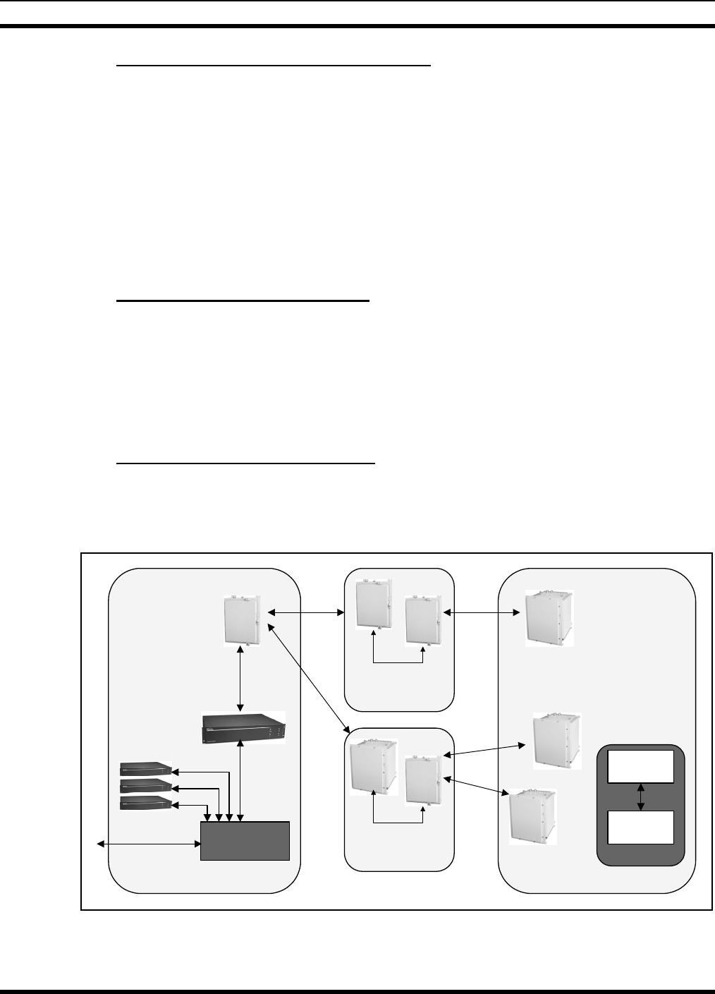
3.6.2 Cell-Drop-and-Repeat Operation
In a Cell-Drop-and-Repeat setup, one radio operates as a standard Slave in communication with the
primary tower site. A second radio at a repeater site or Cell-Drop-and-Repeat site is configured as a
Master radio similar to a tower site.
Air link
(2.4GHz)
ISM
Master
Backhaul
Router
Network
Port
10BaseT
Tower Site
DCX
Cell Site 1
Cell Site 3
Cell Sites
ISM Radio
(Slave)
OpenSky
Base Station
Cell
SLIP
Fiber Interface
Cell Drop &
Repeat Site
ISM
Master
Cell Site 2
Air link
(2.4GHz)
Intranet Cell Site 4
Fiber Interface
Repeater Site
ISM
Master
ISM
Slave
Network
Access Router
Figure 3-2: ISM Repeater Cell-Configuration Setups
The interface between the repeater radios uses the fiber optic network port for data communications.
17

MM102365V1 R1A
3.7 TECHNICAL ASSISTANCE
Should this equipment require repair, or if there are any questions or concerns about the installation of
this equipment, contact M/A-COM’s OpenSky Customer Service using the following numbers:
U.S. and Canada: 877-OPENSKY (877-673-6759)
Worldwide: 978-442-4460
Fax: 978-442-5353
18
MM102365V1 R1A
4. UNPACKING AND CHECKING EQUIPMENT
Before unpacking, installing or operating the ISM Network equipment, read this section of the manual
thoroughly. It contains details pertinent to unpacking and handling instructions, and safety precautions to
protect users and equipment.
4.1 UNPACKING EQUIPMENT
The ISM radio and Backhaul Router are each shipped in separate transit packages. The associated cabling
and accessories for each unit, if any, are shipped in separate containers.
When unpacking the equipment, check the contents against the packing list. Contact your M/A-COM
OpenSky representative and the carrier if any discrepancies are noted.
NOTE
Save the shipping cartons and packing materials in case the equipment needs to be shipped
back to the M/A-COM for service.
The radio contains ESD sensitive components. Only qualified personnel should open the
chassis door.
4.2 INSPECTING AND INVENTORING EQUIPMENT
Carefully unpack the equipment and examine each item. If there is any damage to the equipment, contact
the carrier immediately and have their representative verify the damage. If you fail to report the shipping
damages immediately, you may forfeit any claim against the carrier.
CAUTION
After removal from the carton, examine the radio and Backhaul Router for broken,
damaged, loose or missing parts. Examine the RF connector(s), circular power connector
and ground lug for cracks, bent or damaged threads, or damage to any paint or seals. If any
are noted, contact OpenSky Customer Service immediately to discuss and arrange the
return of the equipment to M/A-COM for replacement. Any unauthorized attempts to
repair or modify this equipment will void the warranty and could create a safety hazard.
19
MM102365V1 R1A
5. PRE-INSTALLATION CONSIDERATIONS
CAUTION
Do not proceed with installation until earlier sections of this manual have been studied
and safety precautions and hazard warnings read and understood.
Failure to follow installation guidelines could pose physical danger along with the risk of
permanently disabling equipment.
Qualified professional technicians must install this equipment.
5.1 CHECKLIST
Prior to installation, ensure the following are at hand:
• Backhaul Router with latest software
• ISM radio to be configured as a Tower Top radio with latest software
• ISM radios to be configured as Cell Site radios with latest software
• Power/Fiber Optic Cables
• Antenna System for the Tower Top Radio
• Antenna System (one for each slave site).
NOTE
See Section 6.2.1or the ISM Network Design Guide for antenna recommendations.
5.2 BACKHAUL ROUTER INSTALLATION CHECKLIST
The Backhaul Router Installation Checklist (shown in Section 11) documents each router’s pertinent data
and lists the procedures for initial hardware installation of a new Backhaul Router.
• Photocopy this checklist prior to installation.
• Annotate the checklist as each action is completed.
• If a Site Log is kept, include a copy of this checklist for each Backhaul Router at the site.
20
MM102365V1 R1A
5.3 PREPARATION FOR FIELD INSTALLATION
Prior to actual field installation, installers should be provided an outline of the ISM network design. The
ISM and IP address of each ISM device and the IP address of the Base Station/DCX at each cell site
should also be obtained. This information should be recorded on the ISM Network Design forms found in
Section 11.
• Photocopy the ISM Network Design form prior to installation.
• Enter the data for each radio or cell site on the form.
• Once data is collected, it is possible to set up the ISM network in a test lab, prior to field deployment.
5.4 SAFETY RECOMMENDATIONS
The guidelines should be studied prior to working on the Backhaul Router or any equipment powered by
electricity.
• Locate the emergency power-off switch. In the event of an electrical accident, it is necessary to turn
off the power quickly.
• Power should be turned off and cord unplugged to eliminate all chance of an electrical accident
before installing or removing a chassis or working near the power supplies.
• Installers should not work alone if potentially hazardous conditions exist.
CAUTION
Jewelry must be removed (including rings, necklaces, and watches) before working on
equipment connected to power lines. Metal objects will heat up when connected to power
and ground and can cause serious burns or weld the metal object to the terminals.
5.5 HAZARD WARNINGS
Dangerous Voltages. The Backhaul Router uses –48 VDC or 110 VAC power. These voltages are
dangerous and can cause severe electrical shock. The following precautions must be observed when
operating or maintaining this equipment.
• Never alter or disconnect the ground connection on the unit or the power cord.
• Never connect an AC source if connected to –48 VDC.
• Never operate this equipment with the covers removed.
WARNING
An electrical shock hazard exists if this device is connected to 230 VAC mains where both
sides of the AC line are floating above ground. The circuit breaker protects only one side
of the AC input line. Even if the circuit breaker opens because of high current, the other
side of the line in a floating system is still energized.
21

MM102365V1 R1A
5.6 ELECTROSTATIC DISCHARGE
ElectroStatic Discharge (ESD) can damage equipment and impair electrical circuitry. It occurs when
electronic components are handled without adequate precautions or proper earth grounding and can result
in complete or intermittent failures.
ESD-prevention procedures must be followed when removing and replacing components.
• Ensure that the chassis is electrically connected to earth ground.
• Installers must wear an ESD-preventive wrist strap and ensure it makes good skin contact. To
properly guard against ESD damage and shocks, the wrist strap and cord must operate effectively.
• The clip must be connected to an unpainted surface of the chassis frame to safely channel unwanted
ESD voltages to ground.
• If no wrist strap is available, grounding can be achieved by touching the metal part of the chassis.
5.7 CABLING CONSIDERATIONS
When planning the installation of the Backhaul Router to a Network Access Router, it is necessary to
consider distance limitations and potential ElectroMagnetic Interference (EMI) as defined by the
Electronic Industries Association (EIA).
Each installation connection must be planned to accommodate the following unique distance limitations.
5.7.1 Ethernet Connections
The distance limitations for Ethernet 10Base-T indicate a maximum segment distance of 328 feet
(100 m).
5.7.2 ISM Radio Power/Fiber Optic Connections
The distance limitations for the ISM radio power and fiber optic cable indicate a maximum cable length
of 600 feet (183 m). The distance is limited primarily to the voltage drop due to current resistance loss in
the power cable.
5.7.3 Maintenance Port Connection
The maintenance port interface is the EIA/TIA-232 (RS-232C). Travel distance for EIA/TIA-232 signals
is determined by bit rate. Generally, the slower the data rate, the greater the distance a signal can travel.
Table 5-1 shows the standard relationship between baud rate and maximum distance.
22

MM102365V1 R1A
Table 5-1: EIA/TIA-232 Baud for Distance Rates
Data Rate (Baud) Distance
(Feet) Distance (Meters)
2,400 200 60
4,800 100 30
9,600 50 15
19,200 50 15
38,400 50 15
NOTE: The baud rate for the maintenance port is fixed at 19,200 baud, so the
maximum cable limit shall not exceed 50 feet or 15 meters.
23
MM102365V1 R1A
6. INSTALLATION
6.1 TOWER TOP ISM RADIO ENCLOSURE INSTALLATION
The Tower Top ISM Radio Enclosure is designed for mounting outdoors on rooftops and poles, building
sides and the sides of telecommunications towers. It must be properly mounted, cabled, dressed and tied
off, and all grounding cables and interconnections must follow the instructions provided.
CAUTION
Do not proceed with installation until earlier sections of this manual have been studied and
safety precautions and hazard warnings read and understood.
Failure to follow installation guidelines could pose physical danger along with the risk of
permanently disabling equipment.
Qualified professional technicians should install this equipment only.
Cable clamps, mounting brackets, ground clamps and cables for both the radio and Backhaul Router must
follow the specifications set out in this manual as regards the following:
• Chassis ground cables for Tower Top ISM Radio Enclosure, #6 AWG or larger, 7 strands or larger.
• Grounding of outer conductor on RF cable, clamps to use, grounding cable to use.
• Rack grounding cable Backhaul Router.
• Lightning protection device on DC power grounding specifications.
• Fiber Optic cable clamps: what to use, where to tie off and how many feet apart.
• Brackets, bolts etc for mounting radio.
• Termination of antenna port if not used.
6.1.1 Power and Grounding Requirements
The radio operates using +12 VDC to +16 VDC input voltage. Its maximum power requirement is 12
Watts. DC Power is provided via the Fiber Optic Cable assembly (MAIROS0002-XXXXX).
The Enclosure has a grounding lug on the bottom of the chassis. This grounding lug must be connected to
a ground reference using #6 AWG stranded wire or heavier gauge.
6.1.2 Lightning Protection
The Tower Top ISM Radio Enclosure contains integral lightning protection. For tower top installations,
or any installation in which the radio is not co-located with a Backhaul Router, no additional precautions
should be required to protect against lightning.
24
MM102365V1 R1A
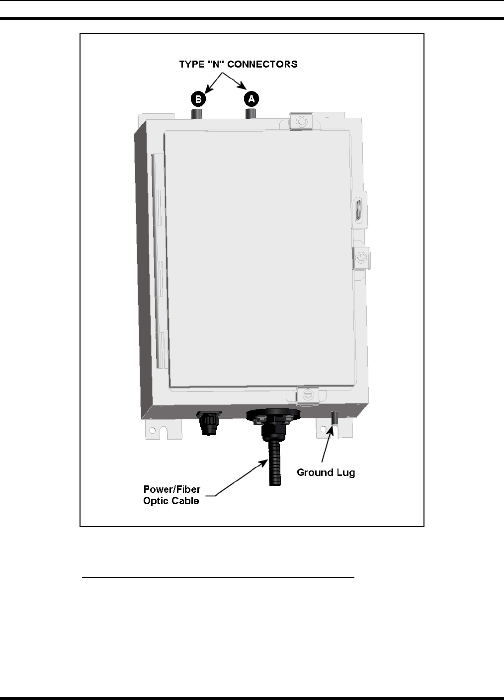
Figure 6-1: ISM Tower Top Radio Enclosure
6.1.3 ISM Radio Co-located with The Backhaul Router
The ISM radio requires DC power in the range of +12 VDC to +16 VDC. The Backhaul Router provides
+15 VDC on its rear panel. When the Backhaul Router is present, it is the preferred power source for the
ISM radio.
Because it is often co-located with a Backhaul Router in a ground-level enclosure, special care must be
taken to protect the Backhaul Router and other co-located equipment from lightning surges and spikes.
25
MM102365V1 R1A
A lightning suppressor should be well grounded and mounted at the egress point to the building (or
enclosure) that houses the Backhaul Router.
A Polyphasor (part number IS-17 VDC-30A-FG) or comparable component may be used to provide
lightning protection on the +15 VDC power lines.
6.1.4 Connect Radio to Another ISM Device
The devices that constitute the ISM network are ISM Master radios, ISM Slave radios, and Backhaul
Routers. An ISM radio can be connected to another ISM device via the RF link, the Network Port, or the
SLIP port. Additionally, the radio uses its SLIP port to connect to an OpenSky Base Station Refer to the
Assembly Diagram in Section 12.2.
NOTE
Where two ISM Cell radios reside at the same site, only the first radio requires an RF link to
the master. The second radio links to the first via the fiber optic connection.
A Master radio is typically located in a tower, physically connected to a co-located Backhaul Router via
the fiber optic port.
6.2 ANTENNA SYSTEM INSTALLATION
This section covers installing the antenna system, including RF cables from the antennas to the ISM radio
enclosure.
Crews trained and equipped for working on antenna towers generally install antenna systems. As a result,
this manual assumes these skilled personnel will be working on the towers and installing the antenna
cables and the Antenna Systems.
6.2.1 Antenna Installation
Factors to consider when choosing the appropriate antenna(s) for your installation include distances to be
covered, number of cells the radio will support, desired link margin, wind load and terrain.
Table 6-1 is a list of antennas that have been tested and approved for use with the ISM radio.
Table 6-1: ISM Antennas
Part Number Manufacturer Antenna
Type Gain Size Weight
SSB-2424GD SSB ELECTRONIC Directional 24 dBi 23.5 x 39.25 x 15 in. 5.4 lbs
ANAD-159W-A-10-SM M/A-COM Directional 16 dBi 12 x 12 in. 1.8 lbs
MFB24006 MAXRAD Omni 6 dBi 11.5 in. 0.38 lbs
MFB24008 MAXRAD Omni 8 dBi 20 in. 0.5 lbs
MFB24010 MAXRAD Omni 10 dBi 36 in. 0.65 lbs
26
MM102365V1 R1A
NOTE
Follow the Antenna manufacturers assembly instructions when assembling the antennas.
Care should be taken that the reflector is installed in the proper direction with the reflector
matching the polarity of the system.
6.2.2 Antenna RF Cable Installation
Depending on the length of cable required for your installation, cable loss, the associated antenna,
budgetary restraints and other factors, either of the cables in Table 6-2 may be used with a 2.4 GHz ISM
Radio System.
Table 6-2: Antenna RF Cables
CABLE PART
NUMBER MANUFACTURER DESCRIPTION LOSS dB/100’ @
2.484GHz
LDF4.5 ANDREW 5/8 in. RF cable 2.65
LDF5 ANDREW 7/8 in. RF Cable 2.02
When installing RF cables, always adhere to the minimum bending requirements provided by the
manufacturer. For Andrew Products, the values are:
CABLE SIZE BENDING RADIUS
5/8-inch 8-inch (200 mm)
7/8-inch 10-inches (250 mm)
Install hoisting grips and cable hangers as required by the System Installation Diagrams provided by the
System Engineer.
Ensure antenna system is properly grounded in accordance with all local and state codes. The
Application Diagrams in Section 12.1 illustrate typical grounding methods.
6.2.3 Antenna System Testing
Upon completion of the antenna system installation, the antenna lines should be tested with a Frequency
Domain Reflectometer (FDR) similar to the Anritsu Site Master model S332C.
1. Disconnect the antenna cable “N” connector from the top of the ISM Radio enclosure.
2. Connect the FDR to the antenna cable “N” connector.
3. Setup the FDR to make sweeps over the band from 2.400 to 2.485 GHz.
4. The output of the sweeps should be archived and left with the customer, installer and project
documentation for future reference when troubleshooting the system.
27
MM102365V1 R1A
6.3 POWER/FIBER OPTIC CABLE INSTALLATION\
This section covers installing the Power/Fiber Optic cable assembly between the ISM Tower Top Radio
enclosure and the shelter demarcation point.
In addition to providing data communication, the Power/Fiber Optic cable assembly also supplies power
to the ISM Tower Top Radio from the Backhaul Router.
CAUTION
Fiber Optic Cable Assembly:
The cable assembly is made with non-conducting materials that can withstand a maximum
crush resistance of 50 lbs.
End pieces and connectors: These components are easily damaged. The bend radius should
be not less than 1.5 in. for this section of the cable assembly.
CAUTION
Weather resistant section: The bend radius should be not less than 6 in. for this section of
the cable assembly.
The assembly must be supported to provide strain relief for the light and fragile ends of the
cable that mount onto the ST connectors on the rear of the Backhaul Router. It must also
have strain relief to support its weight. The cable is not plenum rated. It supports a
maximum hang weight of 200 lb. Maximum hoist length is 1000 ft.
The Power/Fiber Optic cable assembly is available in a number of different lengths. Select the
appropriate length, from Table 6-3, that meets the installation requirements.
Table 6-3: Power/Fiber Optic Cable Assembly Lengths
PART NUMBER LENGTH (feet)
MAIR0S0002-00006 6
MAIR0S0002-00010 10
MAIR0S0002-00025 25
MAIR0S0002-00050 50
MAIR0S0002-00100 100
MAIR0S0002-00140 140
MAIR0S0002-00200 200
MAIR0S0002-00250 250
MAIR0S0002-00300 300
MAIR0S0002-00350 350
MAIR0S0002-00400 400
MAIR0S0002-00450 450
28
MM102365V1 R1A
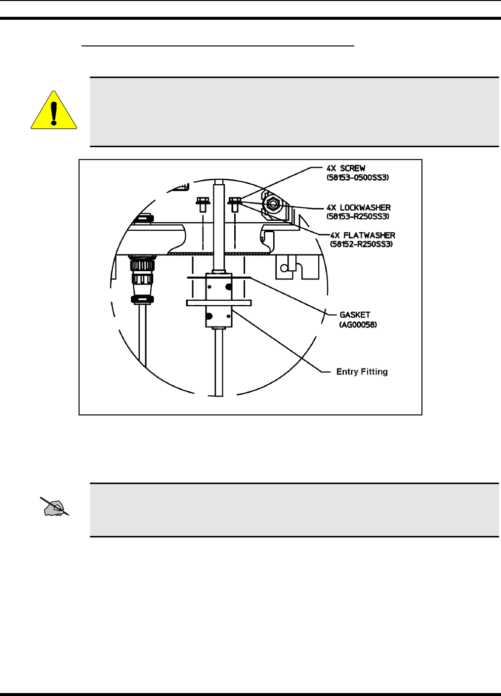
6.3.1 Installing the Power/Fiber Optic Cable Assembly
1. Secure the fiber optic cable to the Tower Top Enclosure as shown in Figure 6-2.
CAUTION
Handle the fiber optical cable assembly with care. It can break easily.
Figure 6-2: Fiber Cable Mounted in Tower Top Radio Enclosure
2. Connect the blue and brown power wires to the surge (input) side of the surge protector as shown in
Figure 6-3.
NOTE
Remove and secure any previously installed wires from the surge protector input before
installing the power lines from the Power/Fiber Optic cable assembly.
3. Connect the green ground wire to the ground stud.
4. Connect RX fiber optic line (1) to the RX port on the ISM radio.
5. Connect the TX fiber optic line (2) to the TX port on the ISM radio.
6. Secure the remaining fiber optic cables and install a tie wrap to secure the cable assembly to the
bracket next to the surge protector.
29
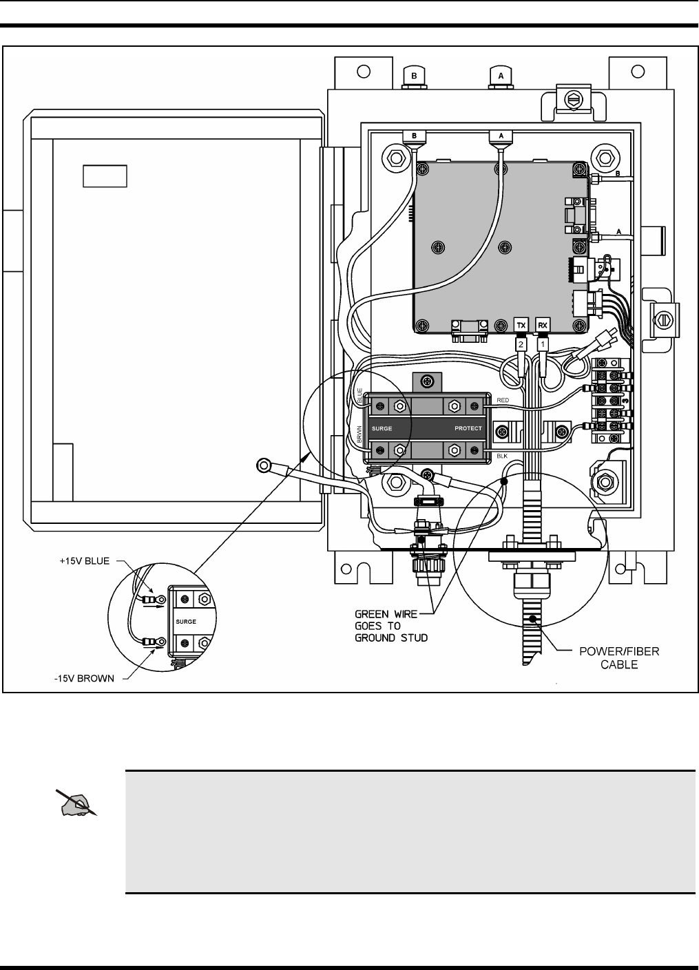
MM102365V1 R1A
Figure 6-3: Wiring the Power/Fiber Optic Cable Assembly
7. Secure the cable assembly to the tower as required.
NOTE
Secure the Power/Fiber Optic cable assembly to the tower using the same process as that
used to secure the antenna RF cable. The cable assembly should also be grounded to the
tower at the same intervals as the RF cables.
When possible, do not bring the excess cable into the shelter. Excess cable should be coiled
and fastened to the underside of the ice bridge.
8. Run the cable assembly through the demarcation point and into the shelter.
9. Connect the fiber optic connectors to the Fiber Optic Coupler.
30
MM102365V1 R1A
10. Connect the ground wire to the Main Ground Bus.
11. Connect the DC power wires the DC Polyphaser.
6.4 BACKHAUL ROUTER INSTALLATION
This section provides information for installing the backhaul Router. The Backhaul Router is available as
an AC powered unit or as a DC powered unit.
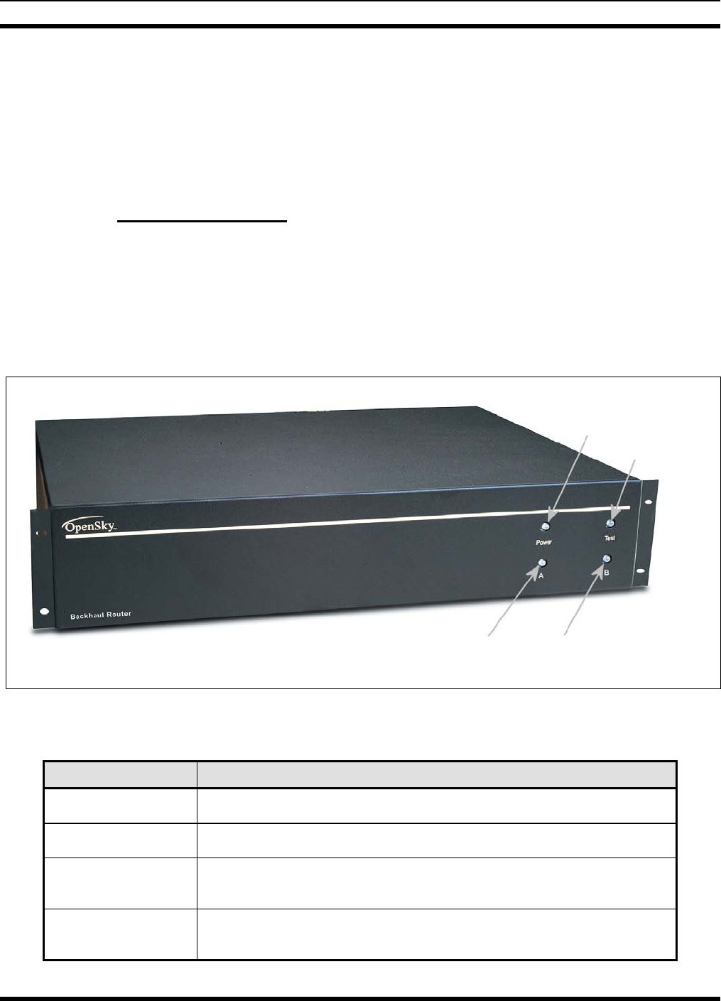
6.4.1 Front Panel Features
The Backhaul Router front panel has four LED indicators:
• Power LED
• Test LED
• Port A RX/TX LED
• Port B RX/TX LED
Figure 6-4: Backhaul Router – Front Panel
Table 6-4: Backhaul Router Front Panel Indicators
LED INDICATOR FUNCTION
Power Solid green whenever power is applied to the Router.
Test Dedicated for system test and maintenance.
Port A RX/TX Flashing indicates packets are being sent or received through the Port A
interface.
Port B RX/TX Flashing indicates packets are being sent or received through the Port B
interface.
PORT A RX/TX PORT B RX/TX
TEST
POWER
31
MM102365V1 R1A
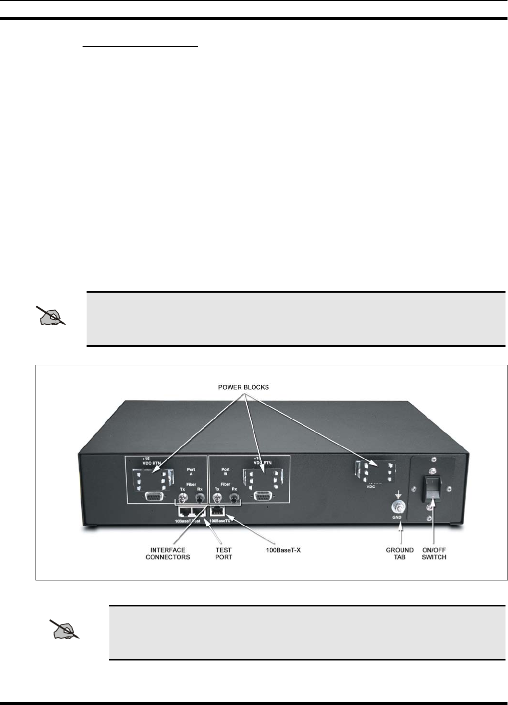
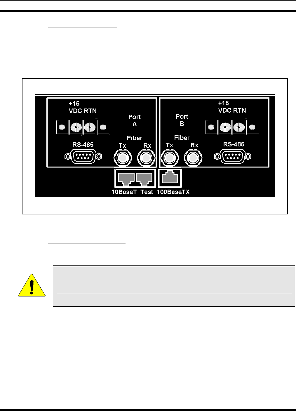
6.4.2 Rear Panel Features
The Backhaul Router rear panel contains the connectors for interfacing with the Tower Top ISM radio
and the Internet router. These connectors include the following:
• Port A +15 VDC (output)
• Port A RS-485
• Port A Fiber TX / Port A Fiber Rx
• 10Base-T LAN Port
• Test or Maintenance Port
• Port B +15 VDC (output)
• Port B RS-485
• Port B Fiber Tx / Port B Fiber Rx
• –48 VDC (input)
• Ground Tab
NOTE
100BaseT-X connector is not used.
Figure 6-5: Backhaul Router – Rear Panel (DC)
NOTE
Backhaul Router AC Version: The DC terminal block is not present and a cover plate
is installed in its place. AC power is provided via a power connector with built in the
circuit breaker.
32
MM102365V1 R1A
6.4.3 Mounting The Backhaul Router
The Backhaul Router is designed for mounting into a standard 19-inch rack in a 2 RU (Rack Unit) space.
It occupies 3.5 inches of vertical rack space and extends approximately 22 in into the rack.
Secure the router in the cabinet using four screws through the router mounting brackets. This is the
preferred method for supporting of the unit when installed in the rack.
CAUTION
Airflow moves through the left and right sides of the chassis. Blocking the sides of the
chassis can impede airflow, leading to dangerous overheating.
Avoid using slide brackets or any other obstruction that restricts airflow.
NOTE
Make sure grounding strap is tied to the Backhaul Router Ground Tab.
6.4.4 Power Cable Installation
WARNING
Dangerous Voltages. The backhaul Router uses –48 VDC or 110 VAC power. These
voltages are dangerous and can cause severe electrical shock.
The following precautions must be observed when operation or maintaining this
equipment.
• Never alter or disconnect the ground connection on the unit or the power cord.
• Never operate this equipment with the covers removed.
• Always disconnect the power cord from the power source when removing or
installing covers, internal components, and wiring.
6.4.4.1 AC Powered Backhaul Router
1. Ensure the Power switch is in the off position.
2. Connect the AC power cord to the rear panel AC power connector.
3. Connect the other end to a circuit breaker protected AC source.
6.4.4.2 DC Powered Backhaul Router
1. Ensure the Power switch is in the off position.
2. Connect the DC power cable to the rear panel -48 VDC power connector.
3. Connect the other end to a power source capable of providing the –48 VDC required.
33
MM102365V1 R1A
6.4.5 Ethernet Connection
The Ethernet port is labeled 10Base-T (see Figure 6-6). It is used to connect the Backhaul Router through
a Hub to a Cisco (or similar) Network Access Router.
Connect an Ethernet cable between the Backhaul Router 10BaseT (RJ-45) connector and the
10/100BaseT connector on the Network Access Router.
Figure 6-6: Backhaul Router – Output Connections
6.4.6 Fiber Optic Connection
The fiber optic cables provide the data communication path to the ISM Tower Top Radio.
CAUTION
Handle the fiber optical cable assembly with care. It can break easily.
There are two ports available: Fiber Optic Port A and Fiber Optic Port B.
The fiber optic cables are often color-coded or numbered. This feature is used as a guide for connecting
the Transmit and Receive lines between the Backhaul Router and the fiber optic coupler or the Tower Top
Radio. The color identifies the same fiber on both ends of the cable.
1. Select a Port. If the router is to be connected to only one ISM Tower Top Radio, use Port A.
2. Connect the fiber optic cables onto the ST connectors on the rear of the Backhaul Router (see Figure
6-6).
3. Connect the Transmit (TX) output on the rear of the Backhaul Router to the Receive (RX) input in the
Tower Top Radio
34
MM102365V1 R1A
4. Connect the Receive (RX) input on the rear of the Backhaul Router to the Transmit (TX) output in the
Tower Top Radio.
6.5 MAINTENANCE AND TEST CONNECTIONS
This section provides information for connecting a Personal Computer (PC) to the ISM radio or the
Backhaul Router for maintenance or testing.
To connect the Backhaul Router to a computer or terminal you must have the proper interface cable. Most
computers and terminals are Data Terminal Ready (DTE) devices. Since the ISM Radio is also a DTE
device, you must use a DTE-DTE interface cable. These cables are also called null-modem, modem
eliminator, or cross over cables.
NOTE
If the terminal is other than a DTE model, an appropriate cable must be used for this
connection.
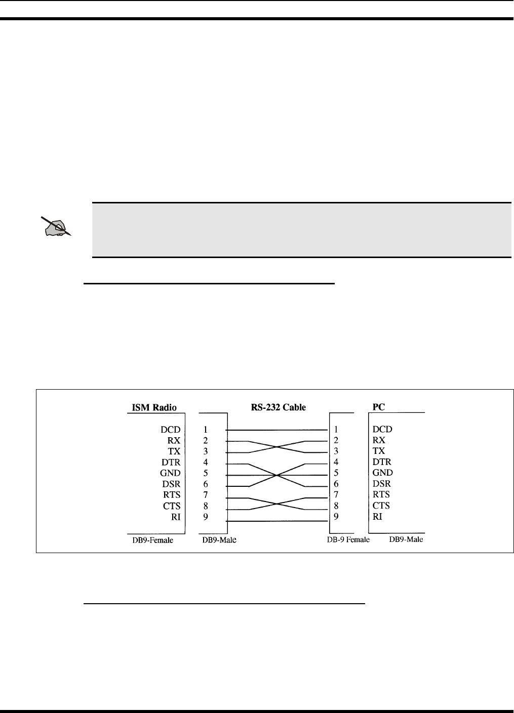
6.5.1 Connecting an ISM Radio to PC or Terminal
The PC to ISM Radio maintenance port interface cable must have the proper connector on each end, and
the internal wiring must be correct.
The ISM radio uses a DB-9 female connector for the maintenance port and the PC usually requires a DB-
9 male connector on its COM port. A female connector has holes inside the connector housing, and the
male connector has pins inside the connector housing. Figure 6-7shows the type needed to connect the
ISM radio to most computers and terminals.
Figure 6-7: RS-232 Cable for Connecting PC to ISM Radio
6.5.2 Connecting Backhaul Router to a PC or Terminal
An RJ-45-to-DB-9 adapter is required to connect the Backhaul Router (TEST) to the PC (see Figure 6-6).
The cable shown in Figure 6-8 can be used to connect the Backhaul Router to most computers and
terminals. Refer to Table 6-5 for connector pin outs.
35
MM102365V1 R1A
Table 6-5: RJ-45 to DB-9 Connections
RJ45 DB-9
4 5
5 3
6 2
3
2
5
3
2
5
3
2
5
DB9
PC
DB9 Null Modem
3
2
5
1 2 3 4 5 6 7 8
DB9
TXD
RXD
GND
RJ45
Figure 6-8: Maintenance Port (TEST) Serial I/O
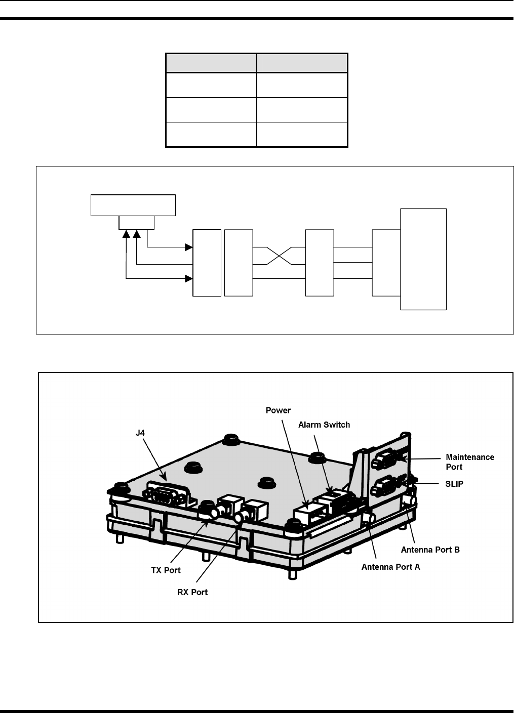
Figure 6-9: ISM radio I/O Connectors
36

MM102365V1 R1A
6.5.3 Maintenance Port Settings
Use the DB-9 to DB-9 RS-232 cable to connect the radio to a computer or terminal. Connect the male end
through the radio’s top connector, also referred to as the maintenance port. See Figure 6-9.
Below are the communication settings for a radio-to-PC or terminal connection.
• Baud Rate: 19200 bits/sec
• Parity: None
• Data Bits: 8 data bits
• Stop Bits: 1
• Flow Control: None
37
MM102365V1 R1A
7. NETWORK CONFIGURATION
7.1 INTRODUCTION
Prior to placing the equipment into operation, it must be properly configured as a system. The following
sections provide instructions for configuring the individual components of the system and setting the
system up as a functioning network.
NOTE
Remote configuration involves the use of the at@send command. It can also be used to
verify the link connectivity among ISM Devices.
All configuration commands are entered from either:
• A 10Base-T Ethernet port through the Network Access Router, or
• A Maintenance port, directly on-site, or other configuration using the maintenance port.
This is typically performed using a PC that has terminal emulation software. The commands can be hand
entered or loaded from a configuration file set up ahead of time.
A list of at* commands and their syntax is available in Section 9. Additionally, Section 8 provides an
example of an ISM network configuration.
7.2 ROUTING TABLES
Logical connections and network topology previously defined as part of the network design are stored in
the routing table.
Typical connections are entered in the routing table through the maintenance port or remotely through
another radio, provided there is a link address for the target radio in the remote radio’s routing table.
NOTE
Instructions containing <Enter> indicates the installer should press the keyboard Enter
key.
38
MM102365V1 R1A
7.3 CONFIGURING THE BACKHAUL ROUTER
The Backhaul Router can be remotely configured by using the at@send command from a local or remote
ISM radio maintenance port.
WARNING
If remote changes are made to the Backhaul Router that impact link or route data, remote
configuration will no longer be available. A site visit to manually connect to the device
may be necessary to restore the link.
The at@send command is used to verify link connectivity among devices connected in the ISM network.
7.3.1 Step 1 – Configure Backhaul ISM and IP Network Addresses
Configure the Backhaul Router with its own ISM address and IP network address.
Table 7-1: ISM and IP Network Addresses
Command Syntax Description
at*addr <ism> Assign Backhaul Router’s ISM address.
at*ip <ip> Assign Backhaul Router’s IP address.
at&w Save configuration table.
7.3.2 Step 2 – Setup Backhaul Routing Table
Add the ISM radio devices that are present in the network to the Backhaul Router routing table. This
includes the base stations that are attached to the Cell Site radios.
Table 7-2: Backhaul Routing Table
Command Syntax Description
at*rtrem * Clear the Backhaul Router routing table entries.
at*rte <ip,type,ism,port> Add entries to the Backhaul Router routing table for each ISM radio
device present in the network, including Cell Base Stations.
at*pwra*[1 | 0] Enables/Disable 15 VDC output at Port A.
at*pwrb*[1 | 0] Enable/Disable 15 VDC output at Port B.
at*mssave Save routing table.
atz Reboot.
39
MM102365V1 R1A
7.4 CONFIGURING THE TOWER TOP RADIO
7.4.1 Step 1 – Configure the Tower Top Radio Topology
Configure the Tower Top radio with its own ISM address, IP network address, radio type, RF slot interval
and Packets Per Interval. Also configure the default destination address so it points to the Backhaul
Router’s ISM address.
Table 7-3: Tower Top Radio Configuration
Command Syntax Description
at*addr <ism> Assign Tower Top Radio ISM address.
at*ip <ip> Assign Tower Top Radio IP address.
at*type 5 Make this ISM a Tower Top Radio.
at*intv 10 RF slot interval.
at*ppi 4 Number Packets per slot Interval.
at*defdest <ism> Default Destination ISM device.
at&w Save configuration table.
7.4.2 Step 2 – Configure the Tower Top Radio Routing Table
Configure the Tower Top radio’s routing table so it contains an entry for itself, the Backhaul Router and
each Cell Site radio it is connected to.
Table 7-4: Tower Top Radio Routing Table Configuration
Command Syntax Description
at*rtrem * Clear Tower Top radio routing table entries
at*rte <ism,ip,type,port,RF index> Add entries to Tower Top radio routing table.
There should be an entry for the Tower Top radio itself, an entry
for the Backhaul Router and entries for each ISM Radio logically
attached to the Tower Top Radio.
at*mssave Save routing table.
atz Reboot system.
40
MM102365V1 R1A
7.4.3 Step 3 – Configure the Tower Top Radio RF Table
Configure the Tower Top radio’s RF table so that it contains an entry for each Cell Site radio in its
network.
Table 7-5: Tower Top Radio RF Entries
Command Syntax Description
at*rfrem * Clear the Tower Top radio RF table entries.
at*rfe <index,antenna,chip,sequence,attennuation,ism> Add an entry to device RF table, for each RF path to
the Tower Top radio.
at*mssave Save RF configuration table.
7.4.4 Step 4 – Configure the Tower Top Radio Frequency List Table
Configure the Tower Top radio’s frequency list table. This table defines the frequencies the Tower Top
radio uses when linking with a Cell Site radio.
Table 7-6: Tower Radio Frequency List Configuration
Command Syntax Description
at*flrem * Clear Tower Top radio frequency list table entries.
at*fle <frequency> Add an entry to device frequency list for each frequency desired.
at*mssave Save frequency list table.
atz Reboot system.
7.4.5 Step 5 – Verification Configuration
Attach PC to the Backhaul Router’s Maintenance port and type the following commands. If the
equipment is operating properly, the requested information is displayed on the PC terminal.
Table 7-7: Verify Configuration
Command Syntax Description
at@send3 at&v Displays parameter stores.
at@send3 at*rfdisp Displays RF table.
at@send3 at*rtdisp Displays route statement.
at@send3 at*fldisp Displays frequency list.
Note: send3 indicates Device # 3
41
MM102365V1 R1A
7.5 CONFIGURING THE CELL SITE ISM RADIO
7.5.1 Step 1 – Configure Cell Site Radio Topology
Configure each individual Cell Site radio with its own ISM address, IP network address, radio type and
default destination ISM device. The default destination ISM should be the Backhaul Router’s ISM
address.
Table 7-8: Cell Site Radio Configuration
Command Syntax Description
at*addr <ism> Assign Cell Site radio ISM address.
at*ip <ip> Assign Cell Site radio IP address.
at*type 3 Make this ISM a Cell Site radio.
at*defdest <ism> Default Destination ISM device.
at&w Save configuration table.
7.5.2 Step 2 – Configure Cell Site Radio Routing Table
Configure the Cell Site radio’s routing table so it contains an entry for the Backhaul Router, the Tower
Top radio and the Base Station to which it is attached. All devices in a spoke from the Tower Top radio
are included in the cell routing table.
A cell routing table does not include other cells unless they are in the same RF daisy chain string created
by a cell drop and repeat configuration
Table 7-9: Cell Site Radio Routing Table Configuration
Command Syntax Description
at*rtrem * Clear Cell Site radio routing table entries.
at*rte <ism,ip,type,port,RF index> Add entry to Cell Site radio routing table.
at*mssave Save routing table.
7.5.3 Step 3 – Configure Cell Site Radio RF Table
Configure the Cell Site radio’s RF table so that it contains an entry that points to the Tower Top radio to
which it is attached.
Table 7-10: Cell Site Radio RF Table Configuration
Command Syntax Description
at*rfrem * Clear Cell Site radio RF table entries.
at*rfe <index,antenna,chip,sequence,attennuation,ism> Add entry to Cell Site radio RF table.
at*mssave Save RF configuration table.
42
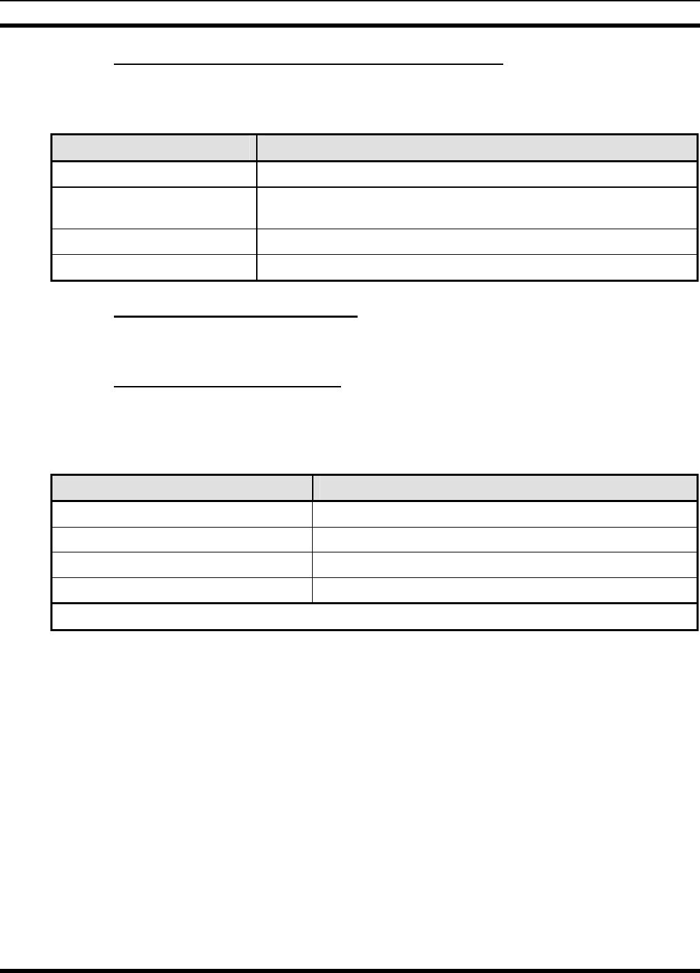
MM102365V1 R1A
7.5.4 Step 4 – Configure Cell Site Radio Frequency List
Configure the Cell Site radio’s frequency list.
Table 7-11: Cell Site Radio Frequency List Configuration
Command Syntax Description
at*flrem * Clear Cell Site radio frequency list entries.
at*fle <frequency> Add entry to Cell Site radio frequency list, for each frequency to be linked
with the master (Tower Top) radio.
at*mssave Save frequency list table.
atz Reboot system.
7.5.5 Step 5 – Connect Test Antenna
Attach test antennas to the Tower Top radio and to the Cell Site radios antenna ports.
7.5.6 Step 6 – Verify Configuration
Attach PC to the Backhaul Router’s Maintenance port and type the following commands. If the
equipment is operating properly, the requested information is displayed on the PC terminal.
Table 7-12: Verify Configuration
Command Syntax Description
at@send3 at&v Displays parameter stores.
at@send3 at*rfdisp Displays RF table.
at@send3 at*rtdisp Displays route statement.
at@send3 at*fldisp Displays frequency list.
Note: send3 indicates Device # 3
43
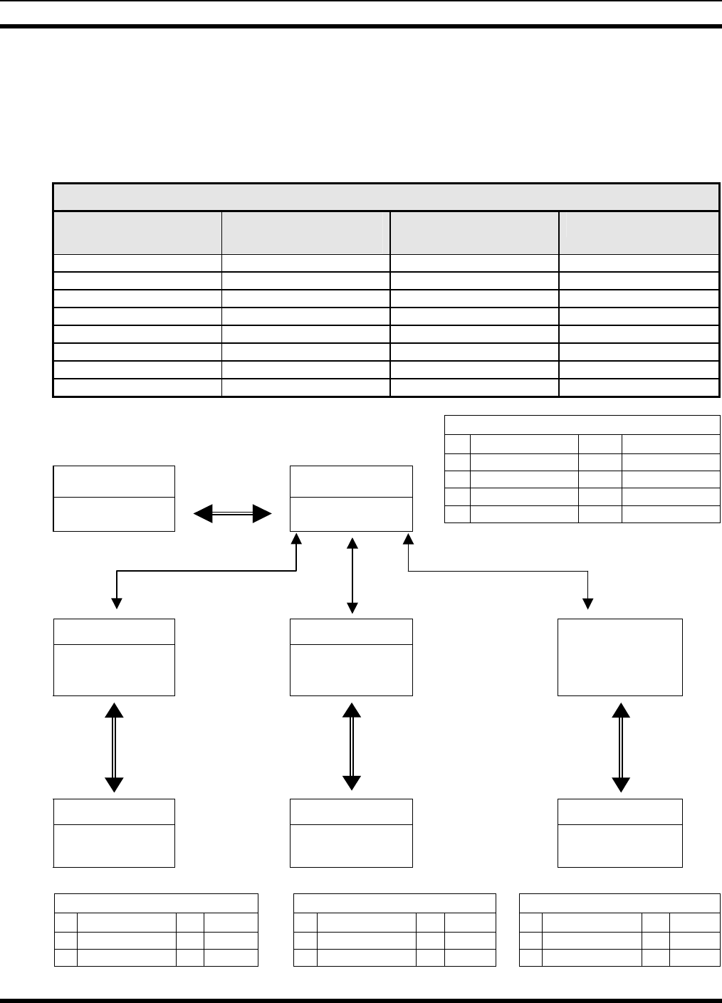
MM102365V1 R1A
8. SAMPLE ISM NETWORK CONFIGURATION
This section contains a sample configuration for an ISM network containing a Backhaul Router, a Tower
Top radio (master), three Cell Site radios (slaves), and three Slip Destinations (Base Stations) in a point to
multi-point configuration.
BACKHAUL ROUTER ROUTING
IP ADDRESS TYPE
(See Section 9.3.2) ISM ADDRESS PORT
172.18.144.34 B 1 This Device
172.18.144.35 T 2 NA
172.18.144.36 C 3 NA
172.18.144.37 S 3 NA
172.18.144.38 C 4 NA
172.18.144.39 S 4 NA
172.18.144.40 C 5 NA
172.18.144.41 S 5 NA
BHR Fiber Tower Top
ISM: 1
IP: 172.18.144.34 ISM: 2
IP: 172.18.144.35
Tower Top Routing Table
2 172.18.144.35 T This Device
1 172.18.144.34 B NP0
3 172.18.144.36 C RF0
4 172.18.144.38 C RF1
5 172.18.144.40 C RF2
RF0 RF2
Cell Site radio #3 Cell Site radio #4 Cell Site radio #5
ISM: 3 ISM: 4 ISM: 5
IP: 172.18.144.36 IP: 172.18.144.38 IP: 172.18.144.40
Base Station Base Station Base Station
IP: 172.18.44.37
IP: 172.18.44.39
IP: 172.18.44.41
Cell Site radio 3 Routing Table
1 172.18.144.34 B RF0
2 172.18.144.35 T RF0
3 172.18.144.37 S Slip
Cell Site radio 4 Routing Table
1 172.18.144.34 B RF1
2 172.18.144.35 T RF1
4 172.18.144.39 S Slip
Cell Site radio 5 Routing Table
1 172.18.144.34 B RF2
2 172.18.144.35 T RF2
5 172.18.144.41 S Slip
RF1
SLIP
SLIP
SLIP
44
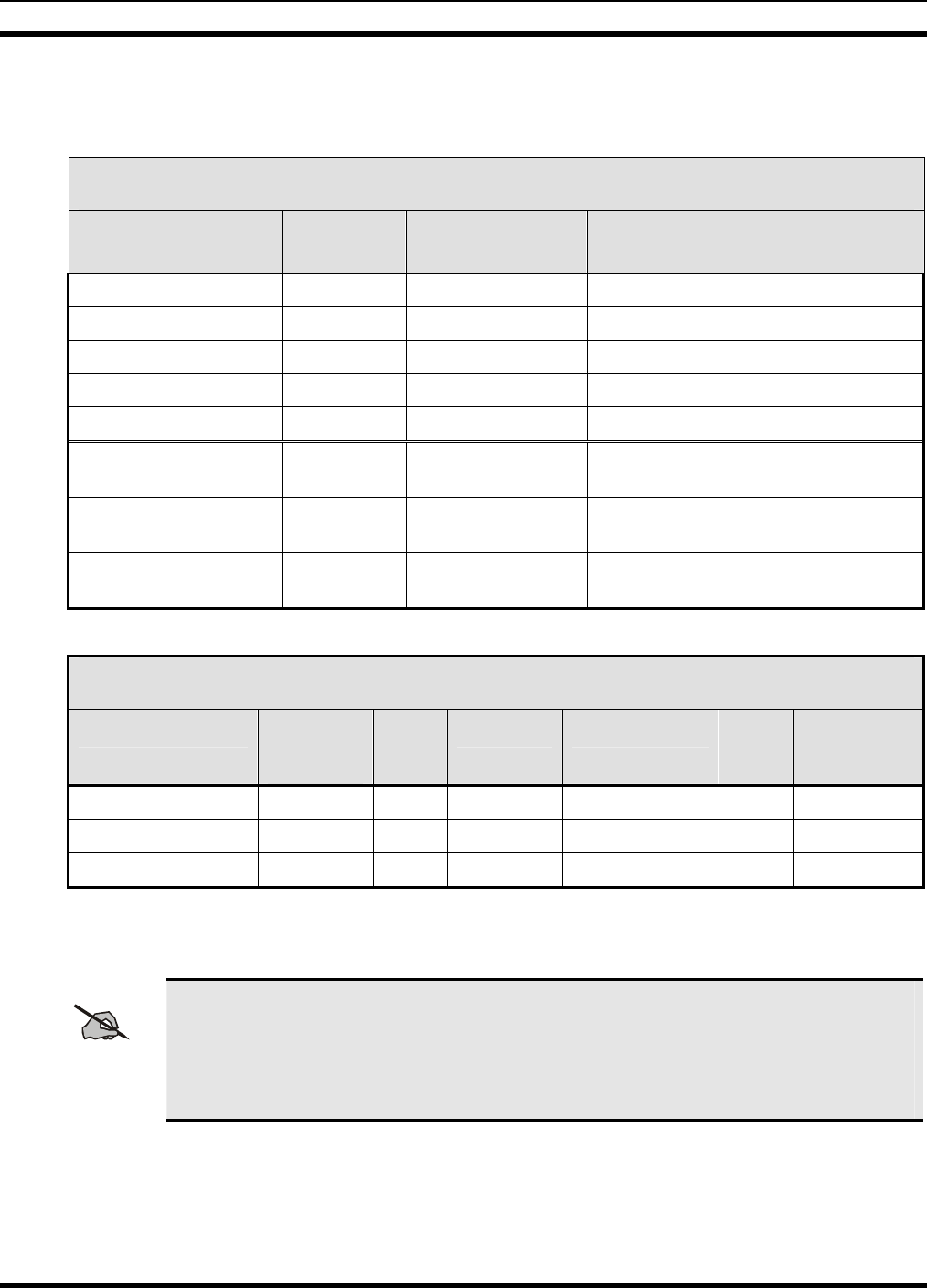
MM102365V1 R1A
8.1 CONFIGURATION PROCEDURE.
Complete the following tables:
ISM Network IP/ISM Design Table
Device ISM
Address IP Address Comments
Backhaul Router 1 172.18.144.34
ISM Tower Radio 2 172.18.144.35
ISM Cell Site radio 3 172.18.144.36
ISM Cell Site radio 4 172.18.144.38
ISM Cell Site radio 5 172.18.144.40
Base Station Cell 3 172.18.144.37 ISM address used is the same as cell ISM
radio address
Base Station Cell 4 172.18.144.39 ISM address used is the same as cell ISM
radio address
Base Station Cell 5 172.18.144.41 ISM address used is the same as cell ISM
radio address
ISM Network RF Table
Device ISM
Address
RF
Port Antenna Attenuation* Chip
Size Spread
Sequence
ISM Cell Site radio 3 0 A 0 11 0x5B8
ISM Cell Site radio 4 1 A 0 11 0x5B8
ISM Cell Site radio 5 2 A 0 11 0x5B8
* If using a 24dBi gain antenna (PMANT25-HD-PF1), a minimum attention of 8dB should be
programmed in.
NOTE
Care should be taken that ISM networks in the same area or that could potentially expose
each other to RF be allocated unique addresses. A convention whereby a figure of ten is
added to each network address that has the potential to cause interference would be a
reasonable convention to employ. For example, network one would be allocated an address
of 1-8, with network two having an address of 11-18 and network three, 21-28.
45

MM102365V1 R1A
8.1.1 Configure Backhaul Router
Configuration Table Commands
at*addr 1 My ISM address
at*ip 172.18.144.34 My IP address
at&w Save configuration table
Routing Table Commands
at*rtrem * Remove any prior entries from table
at*rte 172.18.144.34,b,1,me My entry into the routing table
at*rte 172.18.144.35,t,2,na Tower Radio connected to network Port A
at*rte 172.18.144.36,c,3,na Cell Site radio 3 entry
at*rte 172.18.144.38,c,4,na Cell Site radio 4 entry
at*rte 172.18.144.40,c,5,na Cell Site radio 5 entry
at*rte 172.18.144.37,s,3,na Base station attached to Cell Site radio 3
at*rte 172.18.144.39,s,4,na Base station attached to Cell Site radio 4
at*rte 172.18.144.41,s,5,na Base station attached to Cell Site radio 5
at*udp6425 Sets the UDP port for AT processing
at*np0 Radio set to use fiber optic interface
at*pwra1 Enables 15 VDC output at Port A
at*pwrb0 Disables 15 VDC output at Port B
at*nms_target 0,10.137.0.31,14100,FF,-1
at*nms_target 1,10.128.1.32,14100,FF,-1
at*nms_port6104
at*nms_enable1
NMC Reporting Commands
at*nms_target0,10.134.0.31,14000,FF,2
at*nms_port6103
at*nms_enable1
Allows cell alarms and link status to be remotely monitored via
the NMC
46

MM102365V1 R1A
8.1.2 Configure Tower Radio
Configuration Table Commands
at*addr 2 ISM address
at*ip 172.18.144.35 IP address
at*type 3 Radio type – Tower Radio
at*intv 10 RF interval
at*ppi 4 RF packets per interval
at&w Save configuration table
at*defdest1 Sets the default destination address for this device
at*udp6425 Sets the UDP port for AT processing
at*np0 Radio set to use fiber optic interface
Routing Table Commands
at*rtrem * Remove any prior entries from table
at*rte 2,172.18.144.35,t,m,0 Routing entry
at*rte 1,172.18.144.34,b,n,0 Backhaul Router entry
at*rte 3,172.18.144.34,c,r,0 Cell Radio 3 entry
at*rte 4,172.18.144.38,c,r,1 Cell Radio 4 entry
at*rte 5,172.18.144.40,c,r,2 Cell Radio 5 entry
at*nms_target 0,10.137.0.31,14000,FF,1
at*nms_target 1,10.128.1.32,14000,FF,1
at*nms_port6103
at*nms_enable1
at*mssave Save routing table
atz Reboot Backhaul
RF Table Commands
at*rfrem * Remove all entries from the RF table
at*rfe 0,an,11,5b8,0,3 RF entry for Cell radio 3
at*rfe 1,an,11,5b8,0,4 RF entry for Cell radio 4
at*rfe 2,an,11,5b8,0,5 RF entry for Cell radio 5
Frequency List Commands
at*fle 2412
at*fle 2426
at*fle 2440
at*fle 2454
at*fle 2467
47
MM102365V1 R1A
8.1.3 Verification Commands
Connect the fiber optic cable between the Tower Top radio and the Backhaul Router. Attach PC to the
Backhaul Router’s Maintenance port and type the following commands. If the equipment is operating
properly, the requested information is displayed on the PC terminal.
Verification Table Commands
at@send3 at&v Displays parameter stores
at@send3 at*rfdisp Displays RF table
at@send3 at*rtdisp Displays route statement
at@send3 at*fldisp Displays frequency list
Note: send3 indicates Device # 3
8.1.4 Configure Cell Site Radio 3
Configuration Table Commands
at*addr 3 My ISM address
at*ip 172.18.144.36 My IP address
at*type 5 My radio type – Cell Site radio
at*intv 10 RF interval
at*ppi 4 RF packets per interval
at&w Save configuration table
Routing Table Commands
at*rtrem * Remove any prior entries from table
at*rte 1,172.18.144.34,b,r,0 Backhaul Router’s entry
at*rte 2,172.18.144.35,t,r,0 Tower Radio’s entry
at*rte 3,172.18.144.37,s,s,0 Base station’s entry.
at*mssave Save routing table
atz Reboot Backhaul
RF Table Commands
at*rfrem * Remove all entries from the RF table
at*rfe 0,an,11,5b8,0,2 RF entry for the Tower Radio
Frequency List Commands
at*fle 2412
at*fle 2426
at*fle 2440
at*fle 2454
at*fle 2467
48

MM102365V1 R1A
8.1.5 Configure Cell Site Radio 4
Configuration Table Commands
at*addr 4 My ISM address
at*ip 172.18.144.38 My IP address
at*type 5 My radio type – Cell Site radio
at*intv 10 RF interval
at*ppi 4 RF packets per interval
at&w Save configuration table
Routing Table Commands
at*rtrem * Remove any prior entries from table
at*rte 1,172.18.144.34,b,r,1 Backhaul Router’s entry
at*rte 2,172.18.144.35,t,r,1 Tower Radio’s entry
at*rte 4,172.18.144.39,s,s,0 Base station’s entry.
at*mssave Save routing table
atz Reboot Backhaul
RF Table Commands
at*rfrem * Remove all entries from the RF table
at*rfe 0,an,11,5b8,0,2 RF entry for the Tower Radio
Frequency List Commands
at*fle 2412
at*fle 2426
at*fle 2440
at*fle 2454
at*fle 2467
49

MM102365V1 R1A
8.1.6 Configure Cell Site radio 5
Configuration Table Commands
at*addr 5 My ISM address
at*ip 172.18.144.39 My IP address
at*type 5 My radio type – Cell Site radio
at*intv 10 RF interval
at*ppi 4 RF packets per interval
at&w Save configuration table
Routing Table Commands
at*rtrem * Remove any prior entries from table
at*rte 1,172.18.144.34,b,r,2 Backhaul Router’s entry
at*rte 2,172.18.144.35,t,r,2 Tower Radio’s entry
at*rte 5,172.18.144.41,s,s,0 Base station’s entry.
at*mssave Save routing table
atz Reboot Backhaul
RF Table Commands
at*rfrem * Remove all entries from the RF table
at*rfe 0,an,11,5b8,0,2 RF entry for the Tower Radio
Frequency List Commands
at*fle 2412
at*fle 2426
at*fle 2440
at*fle 2454
at*fle 2467
8.1.7 Verification Commands
Connect the fiber optic cable between the Tower Top radio and the Backhaul Router. Attach PC to the
Backhaul Router’s Maintenance port and type the following commands. If the equipment is operating
properly, the requested information is displayed on the PC terminal.
Verification Table Commands
at@send3 at&v Displays parameter stores
at@send3 at*rfdisp Displays RF table
at@send3 at*rtdisp Displays route statement
at@send3 at*fldisp Displays frequency list
Note: send3 indicates Device # 3
50

MM102365V1 R1A
9. AT COMMAND SET
9.1 USING HELP COMMAND
The Help command is available to remind users or administrators what commands the ISM Radio
supports, and how to access these commands through the maintenance port.
In addition, for any command string, Help can display the associated function.
Finally, Help can also display the range of allowed values that will complete certain text-entry
maintenance and configuration functions.
9.1.1 Accessing the Function Displays
Depending on your familiarity with the ISM Radio functions and the keyboard entries used to launch
them, you can choose to display a complete table or an abbreviated list of command strings only.
9.1.1.1 Display Command String List Only
Type at? <Enter> or simply ? <Enter> to display the full list of commands the ISM Radio supports.
Example:
1. Type at? <Enter> or ? <Enter> to display the Command Strings list.
2. This phrases the Help question: What Command Strings launch which radio functions?
3. In response, the console will display just a list of Command Strings, but not their associated
functions.
9.1.1.2 Display Command String List and Associated Functions
Type at?? <Enter> to display the full list of commands the ISM Radio supports and the Command
strings that launch them.
Example:
1. Type at?? <Enter> to access the full Help menu.
2. This phrases the Help question: Which Command strings launch which radio functions?
3. The console will display a list of Command strings alongside the radio functions they launch.
Table 9-1: Command Strings and Radio/Backhaul Router Functions
Command Strings ISM Radio Functions Backhaul Router Functions
ati Displays Radio Info Displays Backhaul router info
at*addr My ISMR Address My ISMR Address
at*udp UDP PORT for AT Services UDP PORT for AT Services
at*type My Radio Type My Radio Type
at*intv RF Slot Interval
51

MM102365V1 R1A
Command Strings ISM Radio Functions Backhaul Router Functions
at*ppi Number of packets to send every RF
interval
at*rftto Milliseconds to wait after RX for
next TX
at*ip Set Radio IP address Set device IP address
at*defdest Default ISM number for unknown IP
addresses
at*mac Show Ethernet address (hex)
at*np Network Port Type Network Port Type
at*pwra Power Supply A
at*pwrb Power Supply B
at*rtrem Remove RTE Entry Remove RTE Entry
at*rtdisp Display RTE Table Display RTE Table
at*rte Modify RTE Table Modify RTE Table
at*rfrem Remove RF_CONFIG Entry
at*rfdisp Display RF_CONFIG Table
at*rfe RF_CONFIG Table
at*flrem Remove Frequency List Entry
at*fldisp Display Frequency List
at*fle Frequency List
at*mssave Save Master/Slave Config Settings Save Master/Slave Config Settings
ate Enable/Disable Echo Enable/Disable Echo
atv Enable/Disable Verbose mode Enable/Disable Verbose mode
atz Boot into Application mode Boot into Application mode
at&f Restores Non-vol Parameters and
Reboots Restores Non-vol Parameters and
Reboots
at&r Restores Non-vol Parameters without
Rebooting (manual reboot required) Restores Non-vol Parameters
without Rebooting (manual reboot
required)
at&w Saves Non-vol Parameters Saves Non-vol Parameters
at@send Sends String Elsewhere Sends String Elsewhere
at**dbg Debug Flag
at**rfmdisp Display RF Management Info
at**holdmon Force to Monitor and Hold Mode
at**cfreq Changes Current Freq
at**surv Survey a Freq
at**srt Spread Random test
52

MM102365V1 R1A
Command Strings ISM Radio Functions Backhaul Router Functions
at**ttt Two Tone test
at*rssi Display RSSI value
at*temp Display Temperature value
at*batt Display Battery value
at&v Displays All Values Displays All Values
at Ack Only (at? Displays Command
List) Ack Only (at? Displays Command
List)
? Displays Command List Displays Command List
OK
9.1.1.3 Display the Current Value of a Command or Parameter
Typing any command string from the Keyboard Entry list, plus a question mark, will reveal the current
setting of the management command or parameter.
For example, entering the command at*addr? returns the current value of the ISM address.
Example:
1. Type at*addr? <Enter>on the network management console.
2. This phrases the Help question: What is the current setting of at*addr (My ISMR Address)?
3. In response, the console will display the current setting of the ISM Address (for example, 2).
9.1.1.4 Display The Range of Allowed Values for Command Functions
Typing any command string from the Keyboard Entry list, plus two question marks, reveals the range of
values for command parameter.
For example, entering at*addr?? returns the current value of the ISMR Address.
Example:
1. Type at*addr?? <Enter> on the network management console.
2. This phrases the Help question: What are the allowed values for at*addr (My ISMR Address)?
3. In response, the console displays the full range of values that can be selected to describe, in this
example, an ISMR Address (1-99).
9.1.2 Accessing Verbose Information
Rather than displaying the current settings for each command or configuration one at a time, consider
displaying the full range of current settings in one step.
53

MM102365V1 R1A
Example:
1. Type at&v <Enter>at the maintenance port.
2. This phrases the Help question: What are all the current settings for this Radio (Backhaul Router)?
3. In response, the console displays the full list of current settings.
For example (ISM radio):
MY ISMR ADDR: 56
UDP PORT for AT Services: 6425
MY RADIO TYPE: 5
RF SLOT INTERVAL: 40
PACKETS PER INTERVAL: 4
RF transmit timeout: 0
RADIO IP: 192.168.105.4
DEFAULT DEST DEV#: 1
NETWORK PORT TYPE: 0
RTE TABLE: Use at*rtdisp to display details.
RF_CONFIG TABLE: Use at*rfdisp to display details.
FREQ_LIST: Use at*fldisp to display details
ECHO: 1
VERBOSITY: 1
APP MODE: 2
DEBUG FLAG: 8192
OK
For example (Backhaul Router):
MY ISMR ADDR: 2
UDP PORT for AT Services: 6425
MY DEVICE TYPE: 2
DEVICE IP: 192.168.105.4
DEVICE ETHERNET ADDRESS (MAC): 0:10:ec:0:19:b9
NETWORK PORT TYPE: 0
Radio A Power: 0
Radio B Power: 0
RTE TABLE: Use at*rtdisp to display details.
ECHO: 1
VERBOSITY: 1
APP MODE: 1
DEBUG FLAG: 0
OK
9.1.3 Displaying Configuration Information
Two more Help functions allow users/administrators to display the current software version number and
the unique identifier for the equipment.
9.1.3.1 How to Display Serial Number
1. Type ati0 <Enter> at the maintenance port.
2. This phrases the Help question: What is the unique equipment identifier (serial number) for this ISM
Radio (Backhaul Roiuter)?
54

MM102365V1 R1A
3. In response, the console will display the serial number.
9.1.3.2 How to Display Installed Software
1. Type ati4 <Enter>at the maintenance port.
2. This phrases the Help question: What is the revision number of the software currently loaded on this
equipment?
3. In response, the console will display current software data.
For example:
>>>>> ISM Version ISMR001.07 Jan 12, 2001 13:46:22
OK
9.2 SETTING DEVICE PARAMETERS
Logical connections and network topology previously defined as part of the network design is stored in
the routing table.
Connections are typically entered in the Routing Table through the maintenance port or remotely through
another radio. This process of making and saving logic and topography details is known as configuration.
9.2.1 Network Administration
IP Addresses, ISM Addresses, UDP Port Addresses, RF Slot Interval Timing and other Backhaul or radio
functions detailed in the several sections that follow are the responsibility of the network administrator
and are established or changed at the maintenance port or remotely through the 10Base-T Ethernet port.
9.2.2 Changing the ISM Address
ISM devices in the OpenSky Network use ISM Addresses to communicate with each other. Each device
in the ISM sub-network is identified by a unique ISM address (a one- or two-digit number from 1-99).
Example:
1. Type at*addr num at the maintenance port or remotely, where num is the new address of the ISM
device you’re configuring (a unique one-or two-digit number 1-99). Example: at*addr 33
2. Press the Enter key.
3. This sequence states the command: Change the ISM address of this device to 33.
4. The console confirms your change: OK
9.2.3 Changing the IP Address
In addition to the ISM addresses that ISM devices use to communicate with each other within the ISM
Sub-network, every ISM device also uses a unique IP Address to facilitate end-to-end communication
across the entire OpenSky network.
55

MM102365V1 R1A
Example:
1. Type at*ip num.num.num.num at the maintenance port or remotely, where the num sequence is the
new IP address, in the familiar dotted decimal format of IP addresses worldwide (four numbers
between 1-255, without leading zeroes, separated by dots). Example: at*ip 192.168.174.2
2. Press the Enter key.
3. This sequence states the command: Change the IP address of this device to 192.168.174.2
4. The console confirms your change: OK
9.2.4 Displaying Backhaul Mac Address
The Backhaul Router uses a Mac address to translate an OpenSky device IP address into an Ethernet
physical address.
The 10Base-T is an Ethernet port used to connect the Backhaul Router through a Hub to a Cisco (or
similar) Network Access Router. Also, the Ethernet protocol enables remote configuration and
maintenance functions.
Example:
1. Type at*mac on the local or remote console.
2. Press the Enter key.
3. This sequence states the command: Display the Backhaul Router’s Ethernet physical address to
0:10:ec:0:19:b9.
4. The console displays the Mac Ethernet Address in hexadecimal format.
Example: 0:10:ec:0:19:b9
9.2.5 Changing the UDP Port Address
The Backhaul Router or ISM radio uses UDP (User Datagram Protocol to provide services. Service
multiplexing/demultiplexing is achieved at the protocol level with software ports. The AT command
processing uses UDP port 6425 for its service.
Example:
1. Type at*udp port at the maintenance port or remotely, where port sequence is the new specific
service setting for the UDP port. Example: at*upd 6425
2. Press the Enter key.
3. This sequence states the command: Change the service setting of the UDP port to 6425 for AT
command processing.
4. The console confirms your change: OK
9.2.6 Changing Default ISM Destination
The Backhaul Router or ISM radio uses a default ISM destination address to route packets with unknown
IP addresses.
56

MM102365V1 R1A
The function makes it possible to share information among ISM devices without accessing the end-to-end
IP addressing system of the OpenSky network.
Example:
1. Type at*defdest addr at the maintenance port or remotely, where addr is the new default ISM
destination address. Example: at*defdest 14
2. Press the Enter key.
3. This sequence states the command: Change the default ISM destination address for this device to 14.
4. The console confirms your change: OK
9.2.7 Changing RF Slot Interval Timer
The Master Radio initiates all RF communications in TDM (Time Division Multiplexed) order.
In round-robin fashion, the Master ISM addresses all associated Slave radios in turn, giving each the
opportunity to transmit or receive ISM addressed voice and data packets for an amount of time specified
in the RF Slot Interval Timer.
Each Slave device timer can be set for any duration from 1 to 5000 milliseconds.
Example:
1. Type at*intv num at the maintenance port or remotely, where addr is the new RF Slot Interval
setting. Example: at*intv 10
2. Press the Enter key.
3. This sequence states the command: Change the RF Slot Interval Timer for this device to 10
milliseconds.
4. The console confirms your change: OK
9.2.8 Changing RF Packets per Interval
The ISM radio can be configured to send a maximum number of packets over the RF link per RF slot
interval.
While Slave devices in an ISM subsystem can be configured with nonidentical RF Slot Interval Timers,
all Packets Per Interval settings must be identical; either no maximums are set or all radios are set to the
same maximum number of packets.
Example:
1. Type at*ppi num at the maintenance port or remotely, where num is the maximum number of packets
to be sent over the RF link during an RF Slot Interval. Example: at*ppi 4
2. Press the Enter key.
3. This sequence states the command: Set or change the maximum number of Packets Per Interval for
this ISM Subsystem to 4.
4. The console confirms your change: OK
57

MM102365V1 R1A
9.2.9 Changing RF Transmit Delay
An ISM Master Radio can be configured to wait a specified number of milliseconds before transmitting a
packet. However, this is not recommended.
The default setting of zero (0) milliseconds is the preferred and recommended setting for this parameter.
Other settings, because they limit data throughput, may degrade system performance.
NOTE
This is a Master Radio function only. Slave devices may accept an entry in this configuration
field, but will ignore any setting you make
Example:
1. Type at*rftto delay at the maintenance port or remotely, where delay is the number of milliseconds a
Master device will wait before transmitting data packets. Example: at*rftto 10
2. Press the Enter key.
3. This sequence states the command: Set or change the number of milliseconds this device will wait
before sending a packet to 10.
4. The console confirms your change: OK
9.2.10 Changing Mode of Operation
When it comes out of the carton, the ISM Radio is neither Master nor Slave. Its hardware supports both.
How it performs depends on choices you make during configuration and setup.
Even after an ISM device has been configured for Master or Slave operation, its Mode of Operation can
be changed remotely through a Routing Table update or at a terminal connected to the maintenance port.
A single-digit code determines whether the device operates as Master or Slave:
Code Number Mode of Operation
3 Radio operates as Master
5 Radio operates as Slave
Example:
1. Type at*type mode at the maintenance port or remotely, where mode is the code number indicating
Master or Slave mode. Example: at*type 3
2. Press the Enter key.
3. This sequence states the command: Set or change this radio to operate as a Master device.
4. The console confirms your change: OK
9.2.11 Changing Network Port Assignment
The Backhaul Router and ISM radio contain two network hardware interface ports: a fiber optic interface
and an RS-422 port. Software configuration determines which interface port is used for subsystem
communications. The fiber optic interface is the default port.
58

MM102365V1 R1A
NOTE
Slave devices may accept an entry in this configuration field, but it will be ignored.
A single-digit code determines whether the device uses the default fiber optic interface or connects to the
network via the RS-422 port.
Code Number Assigned Port
0 Radio uses the fiber optic interface
1 Radio uses the RS-422 interface
Example:
1. Type at*np type at the maintenance port or remotely, where type is the code number indicating fiber
optic or RS-422 port. Example: at*np 0
2. Press the Enter key.
3. This sequence states the command: Assign the fiber optic port to network use for this device.
4. The console confirms your change: OK
9.2.12 Enabling +15 VDC on Port A or B
The Backhaul Router has output power blocks on Ports A and B that can be used to supply +15 VDC to
ISM radios attached to them.
Use small variations in the procedure below to enable or disable 15 Volts of Direct Current to the power
blocks for either port.
The choice is the responsibility of the network administrator and is established or changed at the local or
remote console, a terminal attached to the maintenance port, or remotely through the 10Base-T Ethernet
port.
Example:
1. Type at*pwra mode on the local or remote console, where pwra identifies Port A as the target (pwrb
identifies Port B) and mode identifies your intention to disable (mode 0) or enable (mode 1) the flow
of current to the power block. Example: at*pwra 1
2. Press the Enter key.
3. This sequence states the command: Enable+15 VDC to the power block on Port A.
4. The console confirms your change: OK
5. To save the change to non-volatile memory, type at&w <Enter>.
59
MM102365V1 R1A
9.3 MANAGING THE ROUTING TABLE
The Routing Table determines where the ISM Radio forwards its packet.
The Network Administrator is responsible for the Routing Table. The table can be generated or changed
at the Network Management Console, a terminal attached to the maintenance port, or remotely through
the 10Base-T Ethernet port.
9.3.1 Saving the Routing Table
Entries in the Routing Table are stored in non-volatile memory and copied into volatile memory after
power is applied to the radio. Changes made only in volatile memory will not survive Power Down.
NOTE
Remember to save changes to Non-Volatile Memory.
The Routing Table like other entries in the configuration table is stored in non-volatile
memory and copied into volatile memory at Power Up. To survive Power Down,
changes must be saved in non-volatile memory. To save changes: type at*mssave Enter.
Remember - Volatile Memory does not survive Power Down. Only changes saved into
Non-Volatile Memory will survive Power Down.
When making permanent changes to the routing table, save them to non-volatile memory so you won’t
lose your changes when the radio is turned-off.
To save the changes, type: at*mssave then press the Enter key.
9.3.2 Routing Table Entries
A single command line made up of several components separated by commas, comprises a Routing Table
entry for an ISM device.
Entry Format:
Routing Table entries take the form: at*rte ism addr, ip addr, type, port, RF link
Where:
Command Purpose
at*rte rte adds a Routing Table Entry (rte) to the configuration for this ISM device.
ism addr A one- or two-digit number between 1-99 that specifies the device’s unique
ISM address within the sub-network.
ip addr IP Address in familiar dotted decimal notation associates the IP address of an
ISM device to its ISM link address.
Continued…
60

MM102365V1 R1A
Command Purpose
type Describes the type of the source device, according to the following:
C Cell radio/slave
T Tower radio/master
B Backhaul Router
S Slip Destination
I IP Source
port Describes which Backhaul Router interface will make the connection path to
the ISM at this address, according to the following:
M This device
N Network port
R RF port
S SLIP port
RF link A number between 0 to 5 that describes RF link associated with this entry. The
RF links are described in the RF configuration table. This value is ignored
unless the port (identified in the parameter field above) is an RF port.
Example:
In the sample Routing Table entry: at*rte 14,192.168.105.3,C,N,0
at*rte is the command line
14 is the device’s ISM address and
192.168.105.3 is the IP address
C designates the device as a cell radio/slave
N indicates the device connects the Network Port
0 describes the RF Link (ignored unless the device connects
through the RF link)
9.3.3 Adding a Routing Table Entry
1. Type a routing table command string at the network management console or maintenance port. For
example: at*rte 14,192.168.105.3,C,N,0. (See Sample Entry above for a breakdown of the
parameters of a routing table entry.)
2. Press the Enter key.
3. This sequence states the command: Add a routing table entry for ISM address 14, IP address
192.168.105.3, a Slave cell radio connected through Network Port.
4. The console confirms the change:
>14,IP(192.168.105.3),c,n
>OK
5. To save the change to non-volatile memory, type at*mssave <Enter>.
61
MM102365V1 R1A
NOTE
Remember to save changes to Non-Volatile Memory.
9.3.4 Removing a Routing Table Entry
The Routing table determines where the ISM Radio forwards its packet. Use the procedure below to
remove a link address from the routing table.
Configuration and changes to the routing table are the responsibility of the network administrator. Entries
are established or changed at the network management console, a terminal attached to the maintenance
port, or remotely through the 10Base-T Ethernet port.
Example:
1. Type the routing table deletion string at*rtrem addr at the network management console or
maintenance port where addr is the ISM address of the ISM device whose entry you wish to delete.
For example: at*rtrem 13
2. Press the Enter key.
3. This sequence states the command: Remove the routing table entry for ISM device 13
4. The console confirms the change:
>Device 13 deleted from RTE table
>OK
5. To save the change to non-volatile memory, type at*mssave Enter
NOTE
Remember to save changes to Non-Volatile Memory.
9.3.5 Displaying Routing Table Entries
To display the complete contents of the Routing Table for an ISM device, use the procedure below.
The Routing Table is the responsibility of the network administrator and can be verified at the network
management console, a terminal attached to the maintenance port, or remotely through the 10Base-T
Ethernet port.
Example:
1. Type a routing table display string at the terminal attached to the maintenance port:
at*rtdisp <Enter>
62

MM102365V1 R1A
2. The console displays a table of routing entries for all networked devices. The table below is entirely
hypothetical; your display will be specific to your particular network setup:
13 192.168.105.2 Backhaul Router This Device 0
14 192.168.105.3 Tower radio RF Port 0
15 192.168.105.4 Cell Radio RF Port 1
OK
9.3.6 NMS Trap Target Entries
This command sets up NMS targets, which will receive the OpenSky NMS traps specified by the mask.
Entry Format:
Routing Table entries take the form: at*nms_target id, ip_address, port, mask, ism id
Where:
Parameters Description
id Target ID (0 or 1)
ip_address IP address of NMS trap server
port Port number for OpenSky NMS trap communications (1–32767)
mask The bit mask defining which traps are sent to the NMC
Bit Description
0 0 - Disable status trap, 1 - Enable status trap
1 0 - Disable fault trap, 1 - Enable fault trap
2 0 - Disable performance trap, 1 - Enable performance trap
ism id This is the device ISM address (0-99). It is applicable to all devices, including
secondary Backhaul Routers, reporting trap data to the NMC through the
primary Backhaul Router (usually device #1).
For Primary Backhaul Routers, this is an exit interface specifier rather than an
ism id. Enter “-1” to correspond to the Ethernet port.
63

MM102365V1 R1A
Example:
In the sample Routing Table entry: at*nms_target 0, 101.202.33.45, 14000, FF, 1
at*nms_target is the command line
0 is the target ID
101.202.33.45 is the NMC IP address
14000 designates the port number
FF is the bit mask
1 is the device ISM address
64

MM102365V1 R1A
9.4 MANAGING THE RF CONFIGURATION TABLE
The RF Configuration Table contains the parameters that control the antenna selection, the attributes of
the PN sequence generator and the power level for the RF transmitter section. Each entry in the table
corresponds to an RF link with another ISM radio. There is a maximum of six entries in this table.
The RF Configuration Table is the responsibility of the network administrator and is established or
changed at the Network Management Console, a terminal attached to the maintenance port, or remotely
through the 10Base-T Ethernet port.
9.4.1 Saving the RF Configuration Table
The RF Configuration Table is stored in non-volatile memory and copied into volatile memory when
power is applied to the radio. Changes are made only in volatile memory and will not survive Power
Down.
When making permanent changes to the RF Configuration Table, save them to non-volatile memory so
you won’t lose your changes when the radio is turned-off.
To save the changes, type: at*mssave then press the Enter key.
NOTE
Remember to save changes to Non-Volatile Memory.
The RF Configuration Table is stored in non-volatile memory and copied into volatile
memory at Power Up. To survive Power Down, changes must be saved in non-volatile
memory. To save changes: type at*mssave <Enter>.
Remember- Volatile Memory does not survive Power Down. Only changes saved into
Non-Volatile Memory will survive Power Down.
9.4.2 RF Configuration Table Entries
A single command line made up of several components separated by commas, comprises an RF
Configuration Table entry for an ISM device.
The parameters of an RF Configuration Table entry are:
• the Table Index, specified by index
• the Transmit and Receive Antenna: antenna
• the Spread Chip size: chip size
• the Spreading Sequence: sequence
• the Transmit Attenuation: atten
• the ISM Link Address: link addr
Entry Format:
RF Configuration Table entries take the form: at*rfe index, antenna, chip size, sequence,atten, addr
65

MM102365V1 R1A
Where:
Parameter Purpose
at*rfe rfe adds an RF Configuration entry (rfe) to the configuration for the ISM
device identified by the index parameter.
index A number from 0 to 5 (for a total of 6 entries per table) uniquely identifying
this link. This parameter (described as the RF Link in the Figure describing
Routing Table Entries) is the number referenced by the Routing Table entries
for a particular ISM device.
antenna
A 2-letter code for the following antenna setups:
Antenna Transmitter Receiver
AN RF Port A RF Port A
AD RF Port A Diversity mode
BN RF Port B RF Port B
BD RF Port B Diversity mode
DD Diversity mode Diversity mode
chip size
The number of bits to be used by the PN sequence generator. Legal entries
for this field are 11, 13, 15 and 16 bits.
sequence
The sequence used by the PN sequence generator.
atten Sets the amount of attenuation to be used in the transmit path. The radio
outputs 30dBm minus the amount of attenuation set in this field.
If using a 24dBi gain antenna (PMANT25-HD-PF1), a minimum attention of 8
dB should be programmed in.
addr A number between 1-99 that specifies the ISM address of the radio at the
other end of this RF link.
Example:
In the following sample RF Configuration Table entry:
at*rfe 0,AN,11,0x54B,4,14
at*rfe is the command line
0 is the unique index indicator for an ISM device
AN is the antenna identifier
11 is the number of bits in a PN sequence
0x54B is the PN sequence used
4 is the amount of attenuation in the transmit path
14 is an ISM address
66
MM102365V1 R1A
9.4.3 Adding an RF Configuration Entry
1. Type an RF Configuration Entry string at the network management console or maintenance port. For
example: at*rfe 0,AN,11,0x54B,4,14
2. Press the Enter key.
3. This sequence states the command: Add an RF Configuration Table entry for ISM device 0, with a
Port A to Port A antenna setup with no diversity on the receive side, a chip size set to 11 bits,
following the PN chip size sequence of 54B (hexadecimal), with 4 dBm attenuation in the transmitter
power level, at ISM Address 14.
4. The console confirms your entry: OK
5. To save the change to non-volatile memory, type at*mssave <Enter>.
NOTE
Remember to save changes to Non-Volatile Memory.
9.4.4 Displaying RF Configuration Table Entries
To display the complete contents of the RF Configuration Table for an ISM Master radio and its
associated Slave devices, use the procedure below.
The RF Configuration Table is the responsibility of the network administrator and can be verified at the
network management console, a terminal attached to the maintenance port, or remotely through the
10Base-T Ethernet port.
Example:
1. Type an RF Configuration Table display command at the terminal attached to the maintenance port:
at*rfdisp <Enter>
2. The console displays RF entries for all devices associated with the ISM Master device. The table
below is entirely hypothetical; your display will be specific to your particular network setup:
Index Link in
use Antenna /
Diversity Chip
size Spread
sequence Attenuation ISM Address
0: 1 A without Div 11 0x5b8 10dB 14
1: 1 B without Div 11 0x5b8 10dB 15
2: 0 B without Div 11 0x5b8 10dB 3
3: 0 B without Div 11 0x5b8 10dB 3
4: 0 B without Div 11 0x5b8 10dB 3
5: 0 B without Div 11 0x5b8 10dB 3
67
MM102365V1 R1A
9.4.5 Removing an RF Configuration Table Entry
Each entry in the RF Configuration Table corresponds to an RF link with another ISM radio. Use the
procedure below to remove a link address from the RF Configuration table.
The table is the responsibility of the Network Administrator. Entries are established or changed at the
Network Management Console, a terminal attached to the maintenance port, or remotely through the
10Base-T Ethernet port.
Example:
1. Type the RF table deletion string at*rfrem index at the network management console or maintenance
port where index is the RF link identifier of the ISM device whose entry you wish to delete (a number
from 0 to 5). For example: at*rfrem 0
2. Press the Enter key.
3. This sequence states the command: Remove the RF Configuration table entry for the ISM device at
RF Link 0.
4. The console confirms your change: OK
5. To save the change to non-volatile memory, type at*mssave <Enter>.
NOTE
Remember to save changes to Non-Volatile Memory.
68
MM102365V1 R1A
9.5 MANAGING THE FREQUENCY LIST TABLE
The ISM radio uses the Frequency List Table to establish a communication link with other radios in the
ISM network.
Each entry in the table corresponds to an allowed frequency to be used for linking with other radios.
Allowed frequencies will fall within the range from 2412-2468 MHz.
The Frequency List is the responsibility of the Network Administrator and is established or changed
through a terminal attached to the maintenance port or remotely through the 10Base-T Ethernet port.
9.5.1 Saving The Frequency List Table
The Frequency List Table is stored in non-volatile memory and copied into volatile memory when power
is applied to the radio. Changes are made only in volatile memory and will not survive Power Down.
When making permanent changes to the Frequency List Table, save them to non-volatile memory so you
won’t lose your changes when the radio is turned-off.
To save the changes, type: at*mssave then press the Enter key.
NOTE
Remember to save changes to Non-Volatile Memory.
The Frequency List Table is stored in non-volatile memory and copied into volatile
memory at Power Up. To survive Power Down, changes must be saved in non-volatile
memory. To save changes: type at*mssave <Enter>.
Remember- Volatile Memory does not survive Power Down. Only changes saved into
Non-Volatile Memory will survive Power Down.
9.5.2 Adding A Frequency List Entry
1. Type the Frequency List Entry command at the Network Management Console.
For example: at*fle 2440
2. Press the Enter key.
3. This sequence states the command: Add Frequency 2440 MHz to the list of allowable frequencies for
linking other radios to this ISM device.
4. The console confirms your entry:
2440
OK.
5. To save the change to non-volatile memory, type at*mssave <Enter>.
NOTE
Remember to save changes to Non-Volatile Memory.
69

MM102365V1 R1A
9.5.3 Displaying The Frequency List Table
The ISM radio uses the Frequency List Table to establish communication link with other radios in the
ISM network. Only frequencies listed in the table are available for linking to other ISM devices.
To display the frequency list table, use the command below.
Example:
1. Type the Display Frequency List command at the terminal attached to the maintenance port:
at*fldisp <Enter>.
2. The console displays all available frequencies and their current status. Of course, the table below is
entirely hypothetical; your display will be specific to your particular network setup:
Frequency List
2412 MHz —Status: Unknown
2440 MHz —Status: Unknown
2467 MHz —Status: Unknown
OK
9.5.4 Removing a Frequency List Entry
The ISM radio uses the Frequency List Table to establish communication link with other radios in the
ISM network. Only frequencies listed in the table are available for linking to other ISM devices.
Use the command below to remove a frequency from the list of frequencies available for ISM links.
Example:
1. Type the Frequency List Entry deletion command at*flrem freq at the network management console
or maintenance port where freq is the RF frequency you wish to delete from the list of frequencies
available for RF Links to ISM devices. For example: at*flrem 2440
2. Press the Enter key.
3. This sequence states the command: Remove the frequency 2440MHz from the Frequency List Table.
4. The console confirms your change:
Frequency 2440 deleted from FREQ_LIST
OK
5. To save the change to non-volatile memory, type at*mssave <Enter>.
NOTE
Remember to save changes to Non-Volatile Memory.
70

MM102365V1 R1A
9.6 SAVING CONFIGURATION AND PARAMETER CHANGES
This manual makes repeated reference to the importance of saving configuration changes to non-volatile
memory to make your changes permanent.
The ISM Radio uses both volatile (temporary) and non-volatile (permanent) memory to handle
configuration details. At Power Up, configuration data is copied into non-volatile memory
9.6.1 Saving Configuration Changes
Changes made to the Routing Table, the RF Configuration Table and the Radio Frequency List need to
made permanent so they can be preserved when power to the radio is turned off
9.6.1.1 Temporary Configuration Changes
Changes you make on an ad-hoc basis to address a temporary situation will remain active in volatile
memory until you power the radio down, but will not survive Power Down.
9.6.1.2 Permanent Configuration Changes
When making changes you wish to make permanent, take the extra step of saving them to non-volatile so
you will not lose the changes when the radio is powered down.
To save the changes, type: at*mssave then press the Enter key.
Changes can be saved at the network management console, a terminal attached to the maintenance port, or
remotely through the 10Base-T Ethernet port.
Example:
1. To save changes you make to the Routing Table, the RF Configuration Table and the Radio
Frequency List, type the Non-Volatile Save command at*mssave at the network management
console.
2. Press the Enter key.
3. The console confirms your change: OK
9.6.2 Saving Parameters Permanently
The ISM Radio uses both volatile (temporary) and non-volatile (permanent) memory to handle
configuration details. At Power Up, configuration data and Radio Parameters are copied into non-volatile
memory. Any changes made during a radio session but not saved to non-volatile memory will be lost at
Power Down.
9.6.2.1 Temporary Parameter Changes
Changes you make on an ad-hoc basis to address a temporary situation will remain active in volatile
memory only until you power the radio down.
71

MM102365V1 R1A
9.6.2.2 Permanent Parameter Changes
When making changes to radio parameters you wish to make permanent, take the extra step of saving
them to non-volatile memory so you will not lose the changes when the radio is powered down.
To save the changes, type: at&w then press the Enter key.
Changes can be saved at the network management console, a terminal attached to the maintenance port, or
remotely through the 10Base-T Ethernet port.
Example:
To save radio parameters:
1. Type the Non-Volatile Save command at&w at the Network Management Console.
2. Press the Enter key.
3. The console confirms you change: OK
72

MM102365V1 R1A
10. TROUBLESHOOTING
10.1 OVERVIEW
This document is intended to present some techniques used for determining problems with an ISM link.
The document is not intended to be comprehensive. In many cases not all of the steps will need to be
followed. In other cases an engineer will be needed to go beyond the items offered in this guide. This
guide assumes some familiarity with the product and system such that the ability to connect to the radio
locally and remotely is known.
In general most issues typically fall into three general categories. Most intermittent issues or link
reliability issues will fall into the first two categories. In many cases the issue will turn out to be a
combination of A and B, when the link has been degraded to the point where by the interference level is
now impacting the link.
• RF path or antenna system issues: This can be path obstructions (Trees that have grown, buildings
that have been constructed), antenna failure, alignment changes or water intrusion in the antenna
system.
• Interference issues: Since the 2.4Ghz band is unlicensed interferes can change on a daily basis.
• Other issues: The normal hardware failures of the equipment such as power supply.
In general troubleshooting should be done in a methodical approach and troubleshooting findings should
be documented thoroughly. Use the diagram at the end of the section to go through the link one
component at a time from end to end.
10.2 EQUIPMENT REQUIRED
Listed below are some tools that can be used to aid in troubleshooting:
• For antenna sweep: FDR, Anritsu Site Master S332C or equivalent.
• For interference & alignment: 2.4 GHz Spectrum Analyzer, Anritsu Site Master S332C or Berkely
Varitronics Yellow Jacket Plus.
• Laptop computer with terminal program (Windows HyperTerminal is fine) and straight through DB9
female to male interface cable. For connection to ISM radio.
10.3 REMOTE TROUBLESHOOTING
A tremendous amount of troubleshooting can be done remotely. Further before going on site you need to
be familiar with the system design.
From the NMC:
1. Check the fault browser in the NMC to determine if there are any faults.
2. Check the history browser in the NMC to determine a history of the issues that are occurring on the
link.
3. Are there patterns of outages in clumps or are they evenly spread out? Randomly spread out issues is
an indication of an RF system or interference issue.
73

MM102365V1 R1A
4. Are there specific times of the day that outages occur? This could be an indication of inversion or a
particular interferer that only comes on at specific times of a day.
Remote login to ISM via Urat or equivalent means:
5. Review and check general configurations; at&v2.
6. Review RF configuration; at*rfdisp2.
7. Review frequency list; at*fldisp2.
8. Review routing table; at*rtdisp2.
9. Review current RF state table; at**rfmdisp.
The key items you are looking for is the cfrq field which displays the current frequency and the ena
field which shows the state of the link (l = up; 0 = down).
The address under column 0 is the address of the device on the other end of the link for the row in the
table.
If the current frequency is not the first one in the list, then at one point in time the frequencies prior to
the current frequency in the list (#7 above) has had interference. The radio always starts at the
beginning of the list if it has a problem with the current frequency. If you look at this periodically
over time it will give you a better understanding of what frequencies may be better than others.
10. Review the link Statistics; at*nms_stat; at*nms_clear to clear stats.
Links with issues will show large values in lost connections and packets in error. For good links
these values are very small or zero. Key fields are:
• link state – Should equal 2 when connected in normal operation.
• current frequency – is the RF frequency in MHz that the logical channel number is using.
• lost connections – is a counter that increments every time that a logical channel number loses
connection with its peer (master/slave).
Under receive status group sub fields:
• packets in error – the number of packets that were rejected due to checksum errors,
buffer overflows.
• dropped – the number of packets that have been discarded due to buffer overflow.
10.4 ON SITE TROUBLESHOOTING
Before going on site understand the design:
1. What height and orientation should the antennas be installed at? Verify this against the as-built
drawings.
2. What is the design margin in reference to the signal strength that should be seen at the ISM receiver?
3. What does the path profile look like?
4. Are there potential path obstructions?
2 When debugging an existing link the configuration should be matched to the configuration as installed. Typically if the
configuration is the same then you need to look elsewhere for your problem. With exception to the frequency list you would
not expect your configuration to require to be changed over time.
74
MM102365V1 R1A
5. Are there other of our ISM links in the area?
If so, the configurations of these links should be checked. ISM links that can potentially see each
other should have unique device addresses. With unique address the links can co-exist even if on the
same frequency. If the links do not have unique address the signal strength must be approximately 15
dB better at the capturing receiver.
6. Before intrusive troubleshooting or changes are made to the link, the quality of the link needs to be
documented via the statistics and or a ping test. This will allow a baseline to compare with once
work is done on the link to verify improvement.
Don’t overlook the simple stuff:
7. Does the radio have power?
8. Is the directional antenna pointed in the right direction?
9. Is the antenna feed straight on directional antennas?
10. Is the antenna feed installed with the same polarity as the grid (If grid antenna is used)?
11. Has a porcupine eaten your cell box?
12. Is there exposed connection or areas of possible water intrusion?
13. Are there any obvious sources of potential interference near by?
Once you get through the simple stuff:
NOTE
For debugging, all RF test connections should be connected as close to the radio as possible.
Specifically, unhooking the SMA connection at the radio and hooking the test set to the
semi-ridged cable inside the enclosure is the best location. Be careful not to damage the
semi-ridged cable.
14. Sweep Antenna lines using the FDR. Match the results to the original site sweeps performed during
installation. 3
If original sweeps are not available look for anything out of the normal. If you see any significant
change in the plots, the antenna system should be debugged.
Spare antennas and feed horns should be kept on hand along with the normal antenna system parts
like connectors, feed line and vapor wrap.
15. Turn off both Master and Slave ISM radios.
The master can be powered down remotely from the Backhaul Router.
16. Hook up spectrum analyzer to the antenna system. Set analyzer to look at the entire band (2.400 to
2.485 GHz). Set on peak hold and look for interferers. Look for interferes for at least five minutes.
The more data the better as some interferes may only be present sporadically. 3
17. With the measuring end radio off, put the remote end in SRT (Spread Random Test) mode for two to
five minutes; at**srt on/off cfreq atten ant sec;
For example: at**srt 1 2412 0 A 300 would put in test mode on freq 2412 on antenna port A for 5
minutes.
3 Items 14 & 16 can be done with a test antenna and test feed line to verify interferers and signal strength at RX radio if
antenna system is suspected to be bad.
75

MM102365V1 R1A
18. Measure RX signal strength and compare it to the expected design signal strength. The measured and
designed to signal strength should be within a couple of dB, if not, you have some sort of RF issue. If
the antenna system checks out, the difference could be due to an obstruction in the path.4
Repeat this test on each port to verify the ports on both ends (if so equipped) and to test out each RF
path.
19. Interference avoidance. If the proper signal strength is seen and the antennas check out and you have
some interference on the band in step 14. That is, if interferers are within 10 – 15 dB of the receive
signal, then the link will most likely be impacted.
Try removing frequencies that look congested or bad in step 14 from the frequency list. Any signal
within approximately 6 MHz on either side of the center frequency can impact the link.
20. If your RX signal strength is as expected you may want to verify the forward and reflected power of
the radio. The proper TX power of the radio is ~ 23 to 25 dBm average power and ~ 26-28 dBm
peak.
4 Items 14 & 16 can be done with a test antenna and test feed line to verify interferers and signal strength at RX radio if
antenna system is suspected to be bad.
76
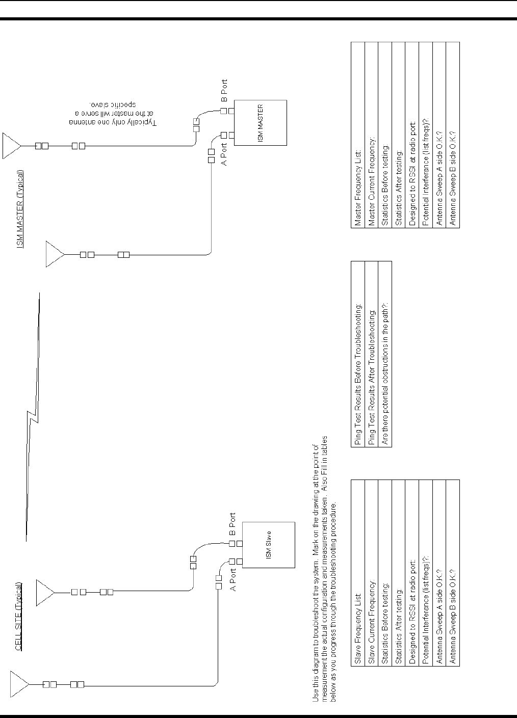
MM102365V1 R1A
Fi
g
ure 10-1: Troubleshootin
g
Dia
g
ram
77

MM102365V1 R1A
This page intentionally left blank.
78

MM102365V1 R1A
11. INSTALLATION CHECKSHEETS
BACKHAUL ROUTER INSTALLATION CHECKLIST
SITE NAME
BACKHAUL ROUTER
SERIAL NUMBER
INSTALLER NAME
SOFTWARE REVISION
Task Check
When
Done
Verified
By Date
SITE POWER VOLTAGES VERIFIED
CABLING CORRECT
REQUIRED TOOLS AVAILABLE
ADDITIONAL EQUIPMENT AVAILABLE
STARTUP SEQUENCE COMPLETED
INITIAL SYSTEM OPERATION
VERIFIED
SOFTWARE REVISION
ROUTING CONFIGURATION SET-UP
CHASSIS GROUNDED
LIGHTNING PROTECTION FOR ISM
RADIO POWER LINES
79

MM102365V1 R1A
ISM NETWORK INSTALLATION CHECKLIST
ISM Network IP/ISM Design
Device ISM Address IP Address Comments
BACKHAUL ROUTER
TOWER TOP ISM RADIO
CELL SITE ISM RADIO
CELL SITE ISM RADIO
CELL SITE ISM RADIO
CELL SITE ISM RADIO
BASE STATION CELL
BASE STATION CELL
BASE STATION CELL
BASE STATION CELL
ISM Network RF Design
Device ISM
Address RF
Port Antenna Attenuation* Chip
Size Spread
Sequence
ISM CELL SITE RADIO
ISM CELL SITE RADIO
ISM CELL SITE RADIO
ISM CELL SITE RADIO
* If using a 24dBi gain antenna (PMANT25-HD-PF1), a minimum attention of 8dB should be
programmed in.
80
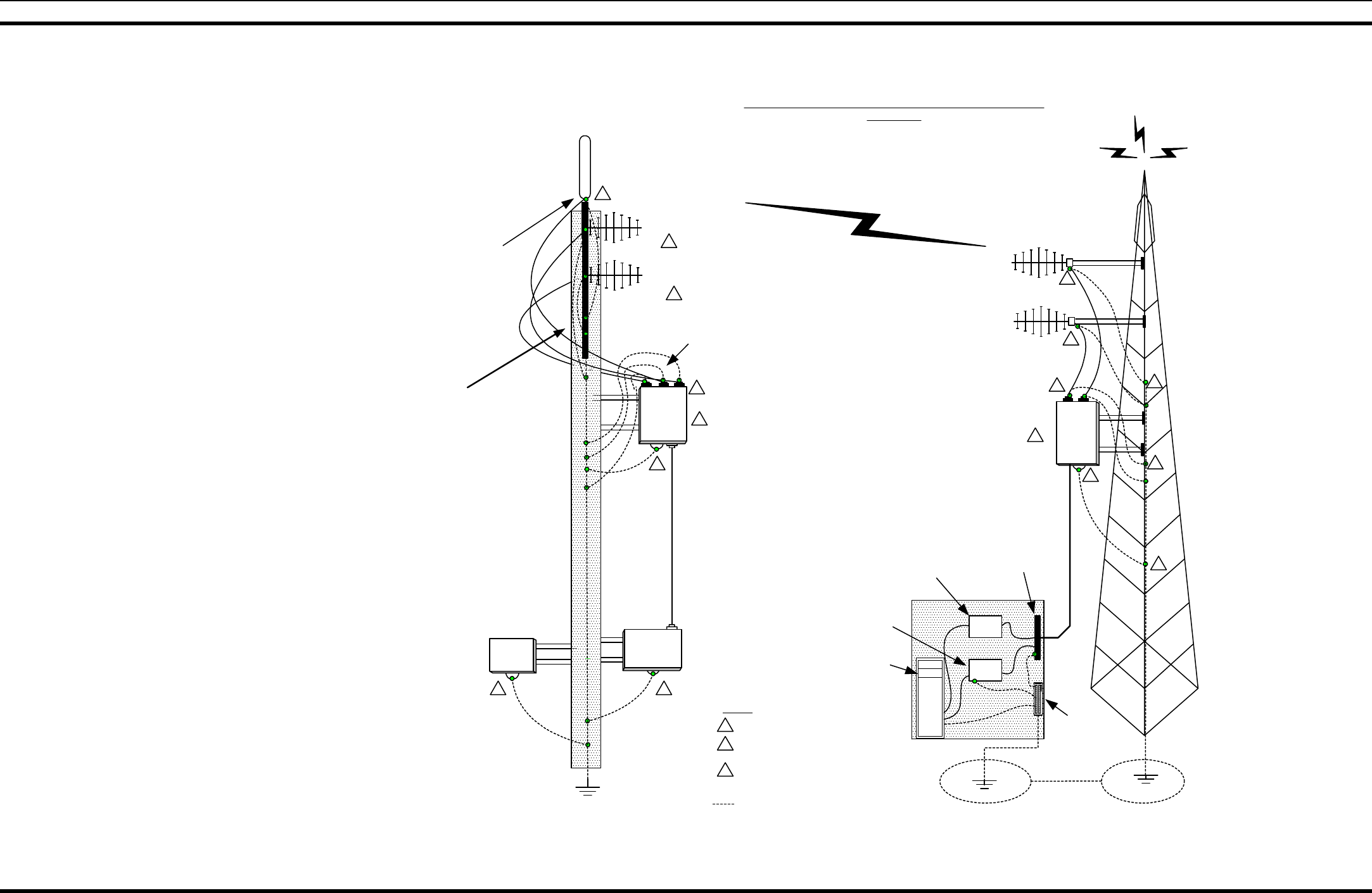
MM102365V1 R1A
12. DIAGRAMS
12.1 APPLICATION DIAGRAMS
Grounding Wire
(Refer to Quality Standards Manual dwg# GQM0221)
1
Main AC Breaker
Antenna TX/RX 800 MHz
(Model to be determined)
TELEPHONE POLE
DC
2
NOTES:
1Grounding Kits
SHELTER
grounding kits at
each end of coax
DC Power &
Battery Backup
ISM Directional
ISM Directional
ISM
MASTER
ISM Directional
ISM Directional
DC/FIBER
Demarcation point
BHR
Back Haul
Router
Main Grounding
Bus
DC Poly-
phaser
Fiber
Coupler
2Chassis Ground
2
2
2
1
1
1
1
1
3
Recommended if system design permits mounting
ISM radio in shelter or near bottom of tower. This
will allow for easy maintance and troubleshooting
of equipemnt
1
1
33
CELL
SITE
1
Only exothermic welds to be
used under ground
(Refer to Quality Standards Manual dwg#GQM0221)
TYPICAL CELL SITE ANTENNA SYSTEM WITH GROUNDING
INCLUDED
3
1
Note: Diversity antenna
system shown on both
ends of link. Diversity may
be used on only the slave
end or not at all.
grounding kits at
each end of coax
Ground wire CAD
welded to antenna
support pipe
8 foot ground rod CAD
welded
TYPICAL CELL SITE ANTENNA SYSTEM WITH GROUNDING
(ISM Typ Inst Dwg, Sh 1, Rev.101403)
81
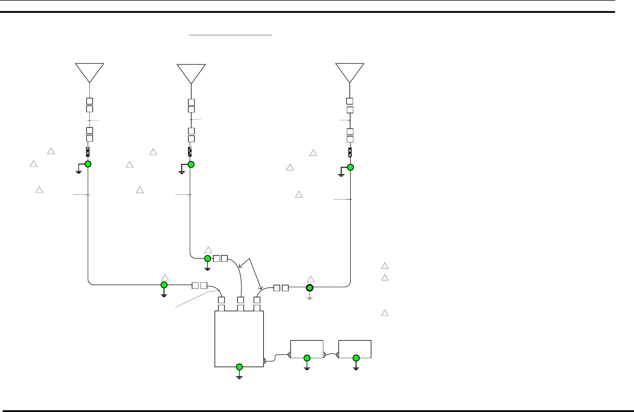
MM102365V1 R1A
Cell Site
GROUNDING KITS
COAXIAL CABLE
LDF5-50A
7/8" if length above 50'
1/2" if length below 50'
HOISTING GRIP
3
1
F4-NMNM-6 FSJ4-50B
(Optional - use with 7/8"
or larger cable)
ANTENNA TX/RX 800 MHz
(Model to be determined)
2
GROUNDING KITS
2
N(M) Connector
N(M) Connector
N(F) Connector
N(F) Connector
DC
Chassis
Ground
Chassis
Ground Chassis
Ground
N(M) Connector
N(F) Connector
GROUNDING KITS
N(M) Connector
COAXIAL CABLE
LDF5-50A
7/8" if length above 50'
1/2" if length below 50'
HOISTING GRIP
3
1
2
GROUNDING KITS
2
2
COAXIAL CABLE
LDF5-50A
7/8" if length above 50'
1/2" if length below 50'
HOISTING GRIP
3
1
F4-NMNM-6 FSJ4-50B
(Optional - use with 7/8"
or larger cable)
ISM DIRECTIONAL ANTENNA
TX/RX 2.4 ISM Band
(Model to be determined)
GROUNDING KITS2
NOTES:
N(M) Connector
N(F) Connector
N(F) Connector
N(M) Connector
N(M) Connector
N(F) Connector
N(F) Connector
N(M) Connector
N(F) Connector
SINGLE CONTINUOUS LENGTH OF CABLE FROM ANTENNA
TO EQUIPMENT ROOM.
EACH GROUNDING KIT IS TO BE TIED TO THE MAIN GROUND
RUN.
GROUNDING KITS ARE TO BE INSTALLED BETWEEN THE LDF
CABLE AND THE TOWER AT THE TOP OF THE LENGTH
WHERE THE CABLE LEAVES THE TOWER AND AT 200 ft.
INTERVAL ON THE TOWER.
IF THE TOWER TO BUILDING LENGTH IS GREATER THAN 5ft.
INSTALL ANOTHER KIT OUTSIDE THE BUILDING ENTRANCE.
ONE HOISTING GRIP FOR EACH 200 ft. OF CABLE.
1
2
3
AC
F4-NMNM-6 FSJ4-50B
(Optional - use with 7/8"
or larger cable)
N(M) Connector
N(F) Connector
F4-NMNM-6 FSJ4-50B
(Optional - use with 7/8" or
larger cable)
N(F) Connector
N(M) Connector
F4-NMNM-6 FSJ4-50B
(Optional - use with 7/8" or
larger cable)
N(M) Connector
N(F) Connector
(Refer to Quality Standards Manual
dwg# GQM0221 for grounding)
CELL SITE ANTENNA ASSEMBLY
Note: Diversity antenna system
shown. If not setup as diversity
system only one ISM antenna
would be used. The antenna
system shown only as an
example. The design engineer
or other responsible party will
define the actual build to
specifications for your system.
DC Power &
Battery Backup Main AC Circuit
Breaker
ISM DIRECTIONAL ANTENNA
TX/RX 2.4 ISM Band
(Model to be determined)
TYPICAL CELL SITE ANTENNA ASSEMBLY
(ISM Typ Inst Dwg, Sh. 2, Rev. 101403)
82
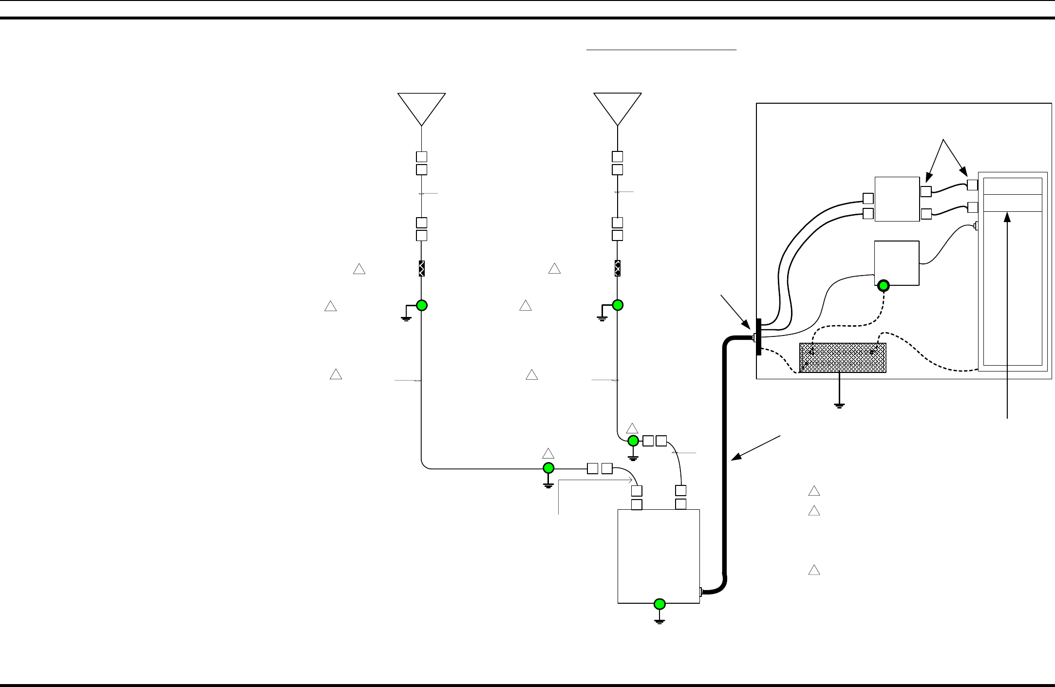
MM102365V1 R1A
GROUNDING KITS
N(M) Connector
COAXIAL CABLE
LDF5-50A
7/8" if length above 50'
1/2" if length below 50'
HOISTING GRIP
3
1
2
GROUNDING KITS
2
2
COAXIAL CABLE
LDF5-50A
7/8" if length above 50'
1/2" if length below 50'
HOISTING GRIP
3
1
ISM DIRECTIONAL ANTENNA
TX/RX 2.4 ISM Band
(Model to be determined)
GROUNDING KITS
2
NOTES:
N(M) Connector
N(F) Connector
N(F) Connector
N(M) Connector
N(M) Connector
N(F) Connector
N(F) Connector
N(M) Connector
N(F) Connector
ISM MASTER
Chassis
Ground
SINGLE CONTINUOUS LENGTH OF CABLE FROM ANTENNA
TO EQUIPMENT ROOM.
EACH GROUNDING KIT IS TO BE TIED TO THE MAIN GROUND
RUN.
GROUNDING KITS ARE TO BE INSTALLED BETWEEN THE LDF
CABLE AND THE TOWER AT THE TOP OF THE LENGTH
WHERE THE CABLE LEAVES THE TOWER AND AT 200 ft.
INTERVAL ON THE TOWER.
IF THE TOWER TO BUILDING LENGTH IS GREATER THAN 5ft.
INSTALL ANOTHER KIT OUTSIDE THE BUILDING ENTRANCE.
ONE HOISTING GRIP FOR EACH 200 ft. OF CABLE.
1
2
3
Demarcation point
BHR
Back Haul
Router
ST Female to
Female fiber
Coupler
ST-Style Male
ST-Style Male
DC
Polyphaser
Main Ground
Bus
SHELTER
F4-NMNM-6 FSJ4-50B
(Optional - use with 7/8" or
larger cable)
N(M) Connector
N(F) Connector
N(M) Connector
N(F) Connector
F4-NMNM-6 FSJ4-50B
(Optional - use with 7/8" or
larger cable )
F4-NMNM-6 FSJ4-50B
(Optional - use with 7/8"
or larger cable)
F4-NMNM-6 FSJ4-50B
(Optional - use with 7/8"
or larger cable)
ISM MASTER ANTENNA ASSEMBLY
ISM DIRECTIONAL ANTENNA
TX/RX 2.4 ISM Band
(Model to be determined)
Power/Fiber Optic Cable
TYPICAL ISM MASTER ANTENNA ASSEMBLY
(ISM Typ Inst Dwg, Sh. 3, Rev. 101403)
83

MM102365V1 R1A
12.2 ASSEMBLY DIAGRAMS
ISM RADIO IN MINI-CELL ENCLOSURE
(Made from BG01214-XX, Sh.8, Rev. D and AU004944, Sh.1, Rev. C)
TO ANTENNA
A
B
Red wire connects to
+12 VDC at 1B
Black wire connects to
RTN at 5B
RF Port A
RF Port B
ISM RADIO
BSC
SLIP Cable
Power
84
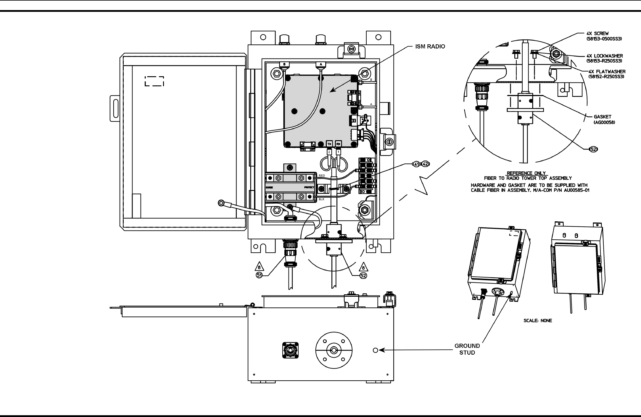
MM102365V1 R1A
ISM RADIO IN TTR ENCLOSURE
(Made from 1000002545, Sh. 3, Rev. E)
85
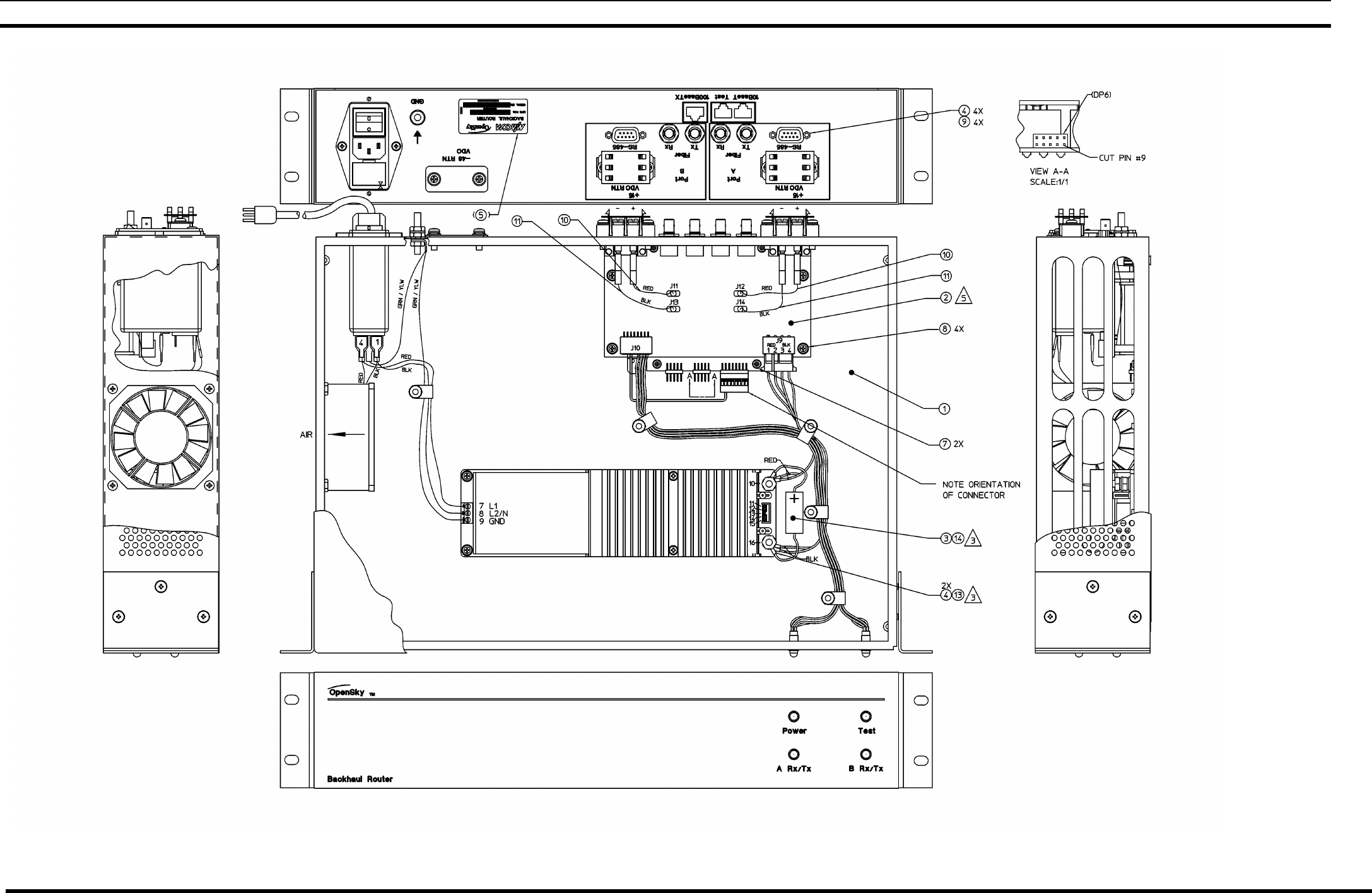
MM102365V1 R1A
AC POWERED BACKHAUL ROUTER
(Made from 1000003826, Sh. 2, Rev. A)
86
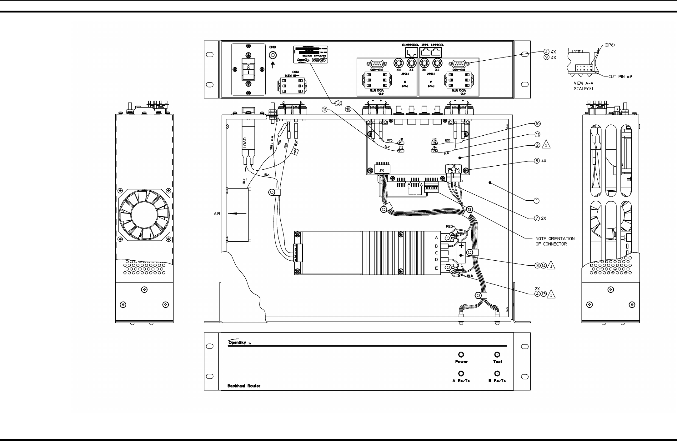
MM102365V1 R1A
DC POWERED BACKHAUL ROUTER
(Made from 1000003823, Sh. 2, Rev. A)
87
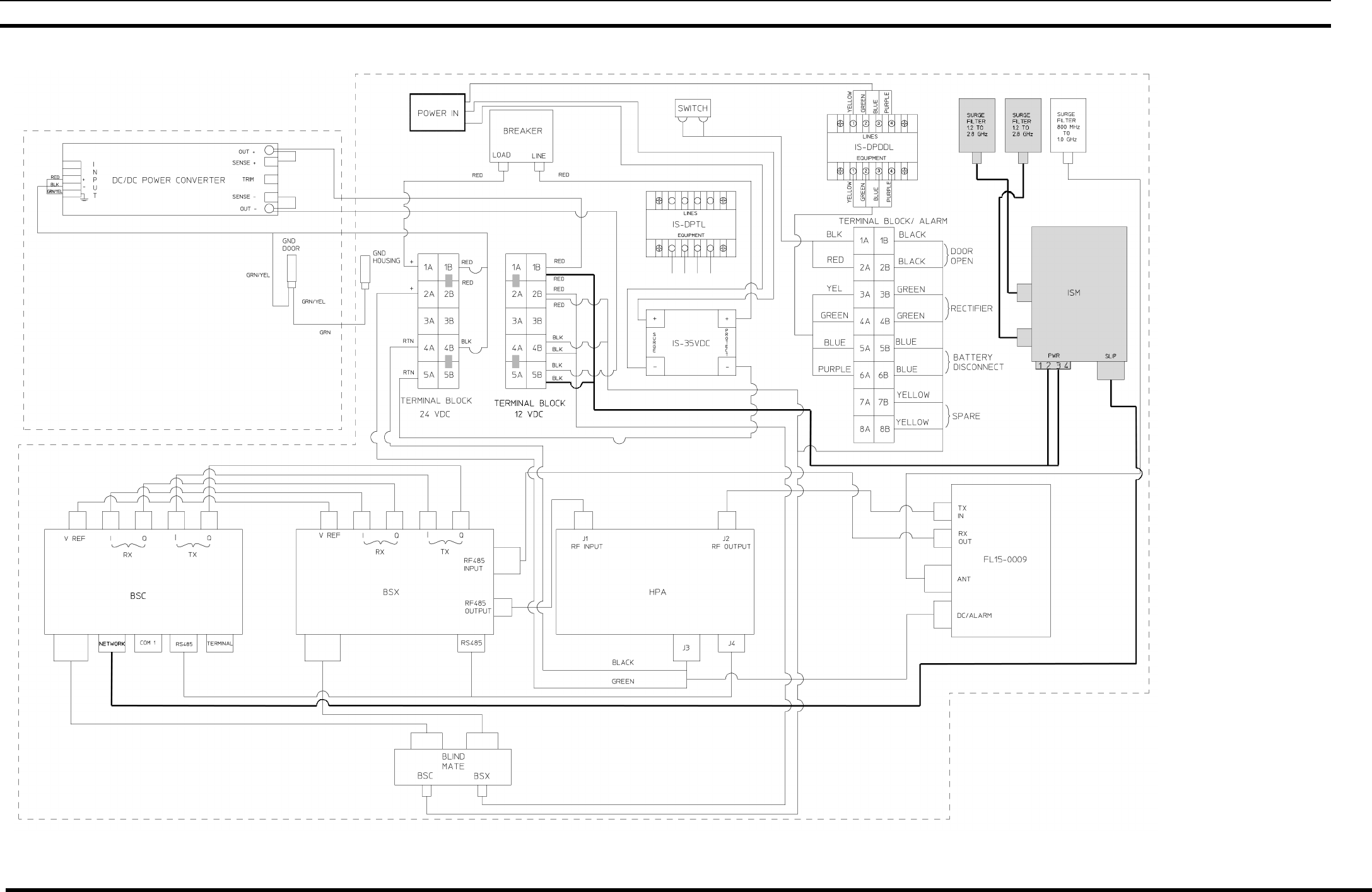
MM102365V1 R1A
12.3 INTERCONNECT DIAGRAMS
ISM RADIO IN MINI_CELL ENCLOSURE
(Made from BG001214-XX, Sh. 14, Rev. D)
88
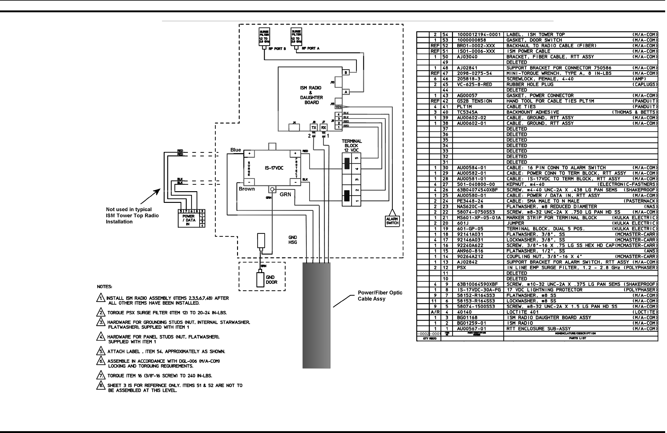
MM102365V1 R1A
ISM RADIO IN RTT ENCLOSURE
(Made from 1000002545, Sh. 1, Rev. E)
89
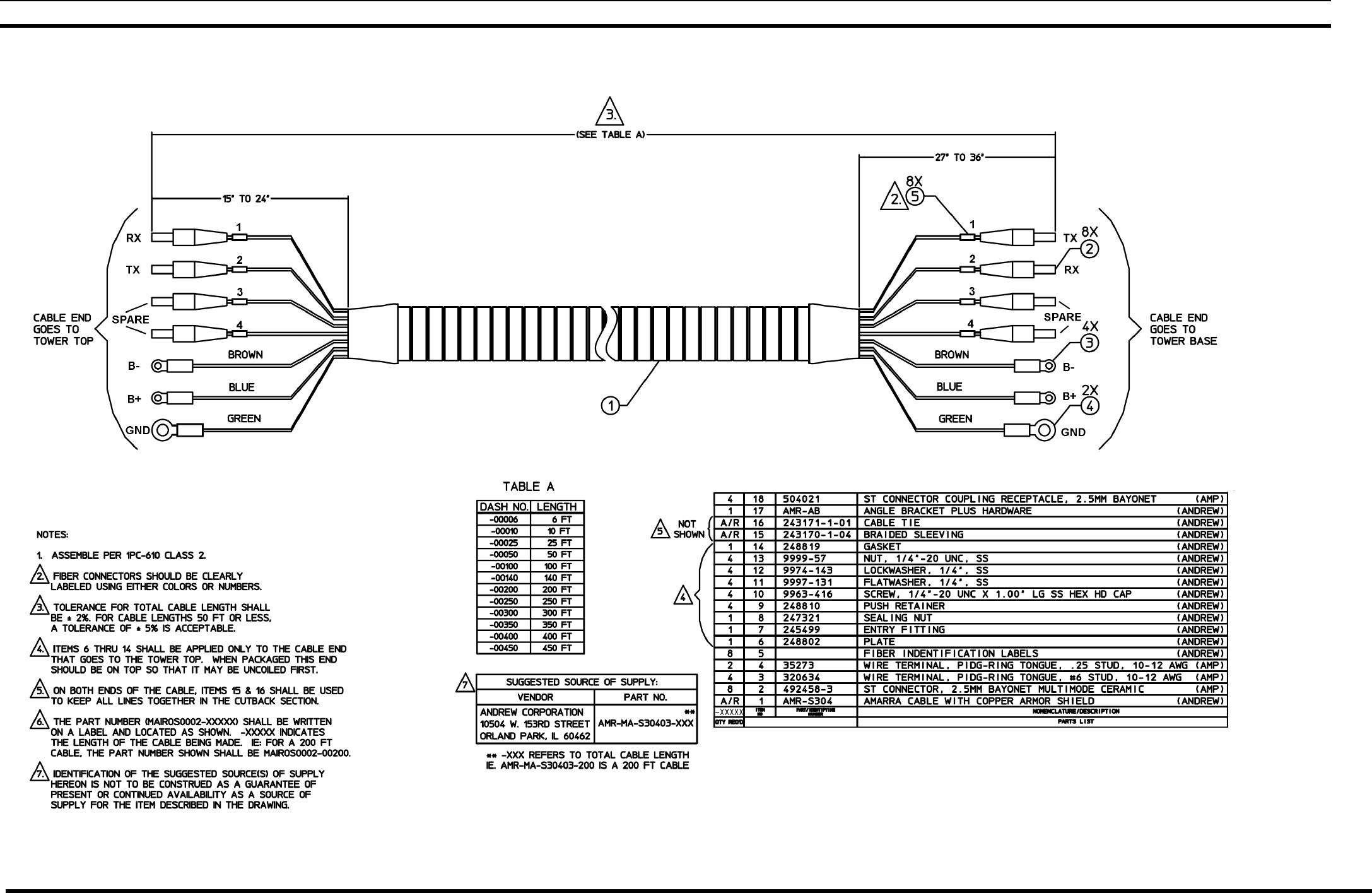
MM102365V1 R1A
12.4 CABLE DIAGRAMS
POWER/FIBER OPTIC CABLE
(MAIR0S0002, Sh. 1 Rev. 0)
90
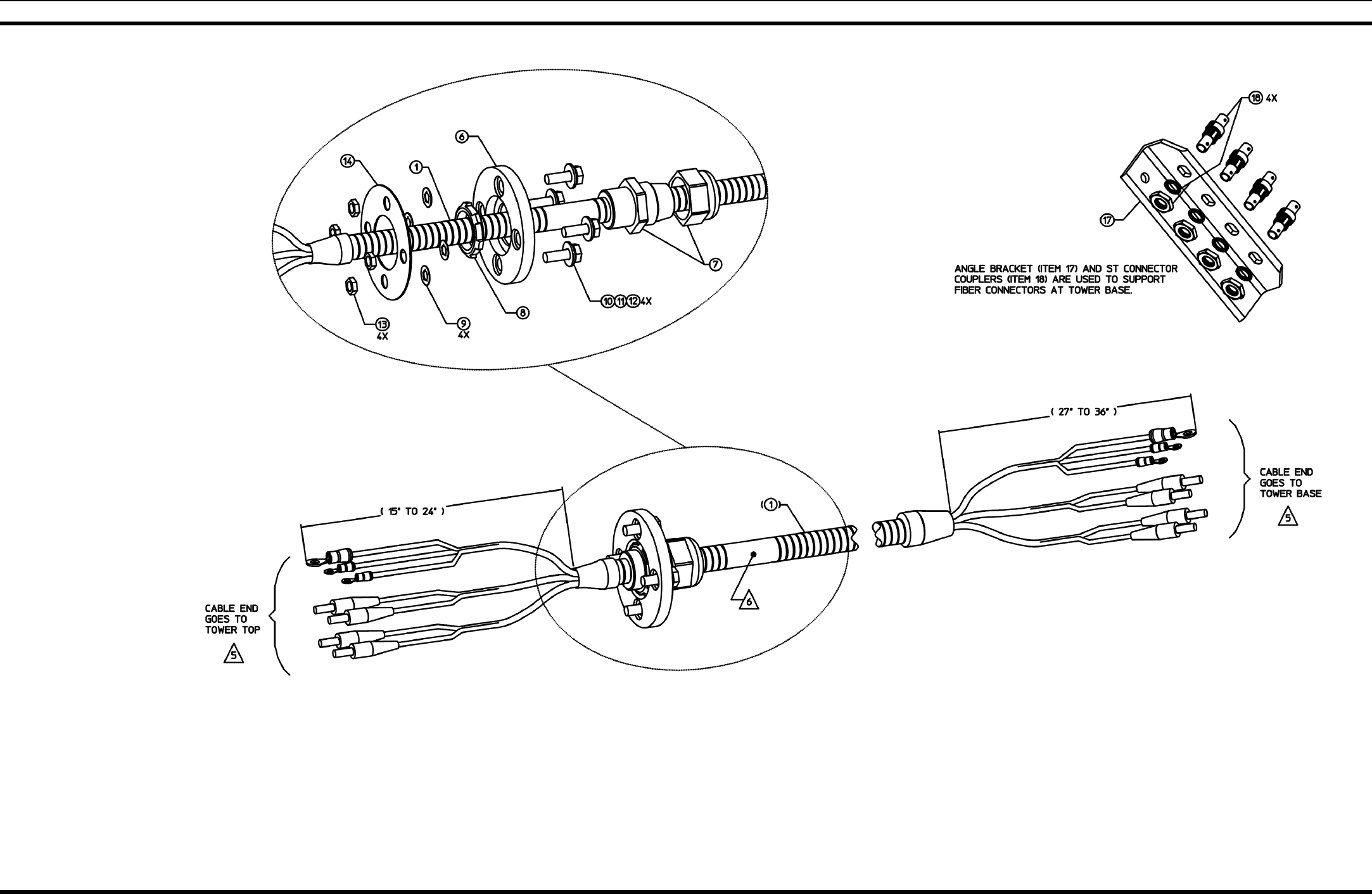
MM102365V1 R1A
POWER/FIBER OPTIC CABLE
(MAIR0S0002, Sh. 2, Rev. 0)
91

M/A-COM Inc.
1011 Pawtucket Blvd.
Lowell, MA 01853
Phone: 978.442.4000
www.macom-wireless.com Printed in U.S.A.