HARRIS TR-0003-A UHF-M Split 450-488 MHz Panther 300P User Manual 2000278 FCC1
HARRIS CORPORATION UHF-M Split 450-488 MHz Panther 300P 2000278 FCC1
HARRIS >
Contents
- 1. App E Manual
- 2. Updated manual
App E Manual

COMPANY NAME: COM NET ERICSSON.
EUT: UHF-M SPLIT 450-488 MHZ PANTHER 300P
WORK ORDER NUMBER: 2000278
FCC ID: OWDTR-0003-A
Page 49 of 61
APPENDIX E
OPERATOR’S MANUAL
MM101027V2
Operator’s Manual
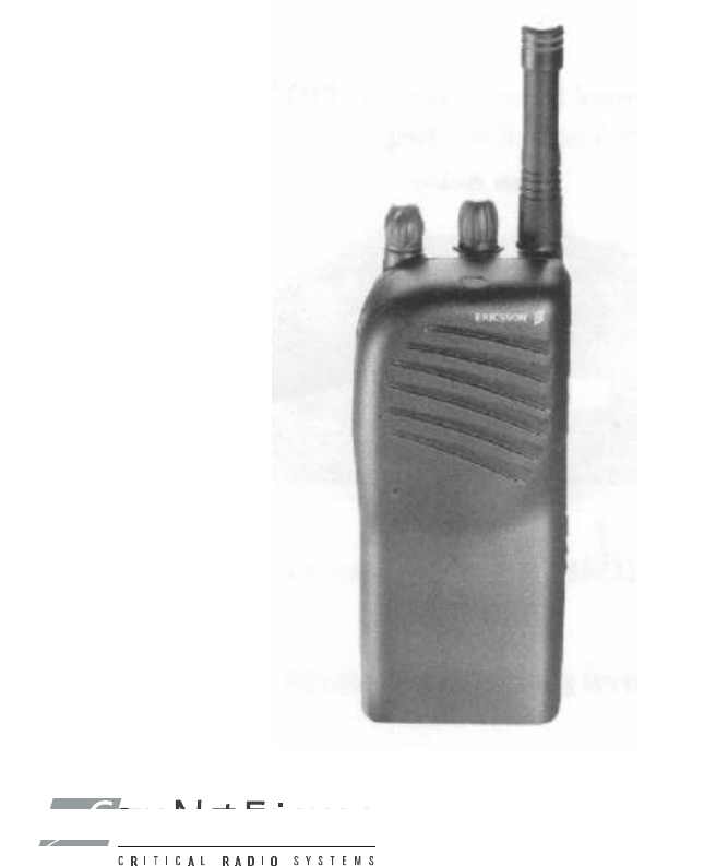
Panther 300P
Mobile Radio
This manual is published by Com-Net Ericsson Critical Radio Systems, Inc.
, without any
warranty. Improvements and changes to this manual necessitated by typographical errors,
inaccuracies of current in
formation, or improvements to programs and/or equipment, may be made
by Com-Net Ericsson Critical Radio Systems, Inc.
, at any time and without notice. Such changes
will be incorporated into new editions of this manual. No part of this manual may be reprodu
ced or
transmitted in any form or by any means, electronic or mechanical, including photocopying and
recording, for any purpose, without the express written permission of Com-
Net Ericsson Critical
Radio Systems, Inc.
Copyright © 1998-2000, Com-Net Ericsson Critical Radio Systems, Inc. All rights reserved.

1
Table Of Contents
SAFETY TRAINING INFORMATION ...................................... 3
SAFE PRACTICE INFORMATION.......................................... 5
OPERATING RULES AND REGULATIONS........................... 6
OPERATING TIPS ...................................................................... 8
INTRODUCTION..................................................................... 9
CONTROLS AND INDICATORS........................................... 10
CONTROLS .............................................................................. 10
OPTION BUTTON FUNCTIONS................................................ 11
Disabled.............................................................................. 11
High/Low Power .................................................................. 11
Monitor/Clear....................................................................... 12
Local/Distant Squelch.......................................................... 12
Type 99 On/Off.................................................................... 12
RADIO INDICATORS ................................................................ 14
Busy / Tx Indicator............................................................... 14
ALERT TONES ......................................................................... 15
Power Up ............................................................................ 15
Carrier Control Timer........................................................... 15
Denied Tone ....................................................................... 15
Failed Tone......................................................................... 15
Option Button Keypress That Disables................................. 15
Option Button Keypress That Enables ................................. 16
Transmitter Disabled ........................................................... 16
Type 99 Individual Call ........................................................ 16
Type 99 Group Call ............................................................. 16
Type 99 Super Group/Quick Call ......................................... 16
Synthesizer Unlock.............................................................. 16
BASIC OPERATION............................................................. 17
TURNING THE RADIO ON........................................................ 17
SELECTING OR CHANGING CHANNELS ................................ 17
TRANSMITTING A BASIC CALL ............................................... 17
CHANNEL GUARD ................................................................... 18
Channel Guard Monitor Function......................................... 18
SELECTIVE SIGNALING...................................................... 19
TYPE 99 OPERATION .............................................................. 20
Receiving An Individual, Group, or Supergroup Call............. 20
Resetting Type 99 After A Call............................................. 21
PROGRAMMABLE PTT FUNCTIONS.................................. 21
Channel Busy Lockout......................................................... 21
Channel Guard Channel Busy Lockout ................................ 21
Type 99 Disable After PTT .................................................. 22
BATTERY OPERATION ....................................................... 22
Removing The Battery......................................................... 22
Attaching The Battery.......................................................... 22
Low Battery Detection And Operation.................................. 23
Battery Error........................................................................ 23

Com-Net Ericsson Critical Radio Systems, Inc. 2
P.O. Box 2000
Lynchburg, Virginia 24501 MM101027V2
1-800-528-7711 (Outside USA, 804-592-7711) Printed in U.S.A.
Table Of Contents (Continued)
Charge The Battery Before Using ........................................ 24
Recharging The Battery....................................................... 24
Conditioning The Battery ..................................................... 24
Battery Care & Maintenance................................................ 25
Battery Recycling................................................................. 25

3
SAFETY TRAINING INFORMATION
Your Com-Net Ericsson radio generates RF
electromagnetic energy during transmit mode. This
radio is designed for and classified as “Occupational
Use Only” meaning it must be used only during the
course of employment by individuals aware of the
hazards and the ways to minimize such hazards.
This radio is NOT intended for use by the “General Population” in
an uncontrolled environment.
This radio has been tested and complies with the FCC RF exposure
limits for “Occupational Use Only.” In addition, your Com-Net Ericsson
radio complies with the following Standards and Guidelines with regard
to RF energy and electromagnetic energy levels and evaluation of such
levels for exposure to humans:
• FCC OET Bulletin 65 Edition 97-01 Supplement C, Evaluating
Compliance with FCC Guidelines for Human Exposure to Radio
Frequency Electromagnetic Fields.
• American National Standards Institute (C95.1 – 1992), IEEE
Standard for Safety Levels with Respect to Human Exposure to
Radio Frequency Electromagnetic Fields, 3 kHz to 300 GHz.
• American National Standards Institute (C95.3 – 1992), IEEE
Recommended Practice for the Measurement of Potentially
Hazardous Electromagnetic Fields – RF and Microwave.

Com-Net Ericsson Critical Radio Systems, Inc. 4
P.O. Box 2000
Lynchburg, Virginia 24501 MM101027V2
1-800-528-7711 (Outside USA, 804-592-7711) Printed in U.S.A.
To ensure that your exposure to RF electromagnetic
energy is within the FCC allowable limits for
occupational use, always adhere to the following
guidelines:
• DO NOT operate the radio without a proper antenna attached, as this
may damage the radio and may also cause you to exceed FCC RF
exposure limits. A proper antenna is the antenna supplied with this
radio by the manufacturer or an antenna specifically authorized by
the manufacturer for use with this radio.
• DO NOT transmit for more than 50% of total radio use time (“50%
duty cycle”). Transmitting more than 50% of the time can cause
FCC RF exposure compliance requirements to be exceeded. The
radio is transmitting when the “TX” light appears in the display. You
can cause the radio to transmit by pressing the “PTT” button.
• ALWAYS use Com-Net Ericsson authorized accessories (antennas,
batteries, belt clips, speaker/mics, etc). Use of unauthorized
accessories can cause the FCC RF exposure compliance
requirements to be exceeded.
• ALWAYS keep the antenna at least 1 cm (0.4 inches) away from the
body when transmitting to ensure FCC RF exposure compliance
requirements are not exceeded. To provide the recipients of your
transmission the best sound quality, hold the antenna at least 5 cm (2
inches) from mouth, and slightly off to one side.
The information listed above provides the user with the information
needed to make him or her aware of a RF exposure, and what to do to
assure that this radio operates within the FCC RF exposure limits of this
radio.

5
SAFE PRACTICE INFORMATION
The operator of any land mobile radio should be aware of certain hazards
common to the operation of radio transmitters. A list of several possible
hazards is given:
1. Explosive Atmospheres - Areas with potentially explosive
atmosphere are often, but not always, clearly marked. These may be
fueling areas, such as gas stations, fuel or chemical transfer or
storage facilities, and areas where the air contains chemicals or
particles, such as grain, dust, or metal powders. Sparks in such areas
could cause an explosion or fire resulting in bodily injury or even
death.
Turn OFF your radio when in any area with a potentially
explosive atmosphere. It is rare, but not impossible that the
radio or its accessories could generate sparks.
2. Electronics Systems - RF energy from your portable radio may
affect some electronic equipment. Most modern electronic
equipment in cars, hospitals, homes, etc. are shielded from RF
energy. However, in areas that instruct you to turn off two-way
radio equipment, always observe the rules. If in doubt, turn it off.
3. Dynamite Blasting Caps - Dynamite blasting caps may be caused to
explode by operating a radio within 500 feet of the blasting caps.
Always obey the "Turn Off Two-Way Radios" signs posted where
dynamite is being used.
When transporting blasting caps in your vehicle:
1) Carry the blasting caps in a closed metal box with a soft lining.
2) Leave the radio OFF whenever the blasting caps are being put
into or removed from the vehicle.
4. Radio Frequency Energy - Do not use a radio with a damaged or
missing antenna. A minor burn may result if a damaged antenna
comes into contact with the skin. Replace a damaged antenna
immediately. A missing antenna could damage your radio. Use only
the supplied or approved antenna. Unauthorized antennas,
modifications, or attachments could damage the radio unit and may
violate FCC regulations.

Com-Net Ericsson Critical Radio Systems, Inc. 6
P.O. Box 2000
Lynchburg, Virginia 24501 MM101027V2
1-800-528-7711 (Outside USA, 804-592-7711) Printed in U.S.A.
5. Always turn off your portable radio before boarding any aircraft.
Use it on the ground only with crew permission. Do not use it in the
air.
6. Safe Driving Recommendations - (Recommended by AAA)
• Read the literature on the safe operation of the radio.
• Keep both hands on the steering wheel and the radio secured
whenever the vehicle is in motion.
• Place calls only when vehicle is stopped.
• When talking from a moving vehicle is unavoidable, drive in the
slower lane. Keep conversations brief.
• If a conversation requires taking notes or complex thought, stop
the vehicle in a safe place and continue the call.
• Whenever using a radio, exercise caution.
OPERATING RULES AND REGULATIONS
Two-way FM radio systems must be operated in accordance with the
rules and regulations of the local, regional, or national government.
In the United States, the PANTHER 300P radio must be operated in
accordance with the rules and regulations of the Federal
Communications Commission (FCC). As an operator of two-way radio
equipment, you must be thoroughly familiar with the rules that apply to
your particular type of radio operation. Following these rules helps
eliminate confusion, assures the most efficient use of the existing radio
channels, and results in a smoothly functioning radio network. When
using your two-way radio, remember these rules:
1. It is a violation of FCC rules to interrupt any distress or emergency
message. As your radio operates in much the same way as a
telephone "party line", always listen to make sure that the channel
is clear before transmitting. Emergency calls have priority over all
other messages. If someone is sending an emergency message - such
as reporting a fire or asking for help in an accident - KEEP OFF
THE AIR!

7
2. The use of profane or obscene language is prohibited by Federal law.
3. It is against the law to send false call letters or false distress or
emergency messages. The FCC requires that you keep conversations
brief and confine them to business. To save time, use coded
messages whenever possible.
4. Using your radio to send personal messages (except in an
emergency) is a violation of FCC rules. You may send only those
messages that are essential for the operation of your business.
5. It is against Federal law to repeat or otherwise make known anything
you overhear on your radio. Conversations between others sharing
your channel must be regarded as confidential.
6. The FCC requires that you identify yourself at certain specific times
by means of your call letters. Refer to the rules that apply to your
particular type of operation for the proper procedure.
7. No changes or adjustments shall be made to the equipment except by
an authorized or certified electronic technician.
Under U.S. law, operation of an unlicensed radio transmitter within the
jurisdiction of the United States may be punishable by a fine of up to
$10,000, imprisonment for up to two years, or both.
IMPORTANT

Com-Net Ericsson Critical Radio Systems, Inc. 8
P.O. Box 2000
Lynchburg, Virginia 24501 MM101027V2
1-800-528-7711 (Outside USA, 804-592-7711) Printed in U.S.A.
OPERATING TIPS
Antenna location and condition is important when operating a portable
radio. Operating the radio in low areas or terrain, under power lines or
bridges, inside of a vehicle or in a metal or steel framed building can
severely reduce the range of the unit. Mountains and buildings can also
reduce the range of the unit.
In areas where transmission or reception is poor, some improvement may
be obtained by ensuring that the antenna is vertical. Moving a few yards
in another direction or moving to a higher elevation may also improve
communications. Vehicular operation can be aided with the use of an
externally mounted antenna.
Battery condition is another important factor in the trouble free operation
of a portable radio. Always use properly charge batteries.
For efficient radio operation, hold the front of the portable radio
approximately three inches from your mouth and speak into the
microphone at a normal voice level. Keep the antenna in a vertical
position when receiving or transmitting a message. Do not hold the
antenna when receiving a message and, especially, do not hold when
transmitting a message.

9
INTRODUCTION
This manual describes the operation for the Com-Net Ericsson Panther
300P Mobile radio. The Panther 300P radio is a high performance FM
mobile radio providing reliable two-way communication in a
Conventional radio system.
The Panther 300P radio can be programmed with up to 6 channels. It
includes a Tx/Busy indicator LED, a Monitor/Clear button, one
programmable option button, and a PTT switch.
The Panther 300P radio can be programmed to operate with any of the
following Conventional radio system platforms:
q Channel Guard (with or without STE)
q Digital Channel Guard
q Type 99
The Panther 300P is a versatile radio designed to meet most
Conventional applications. The 300P radio will be available in
numerous splits in the VHF and UHF bands. The 300P radio can be
purchased with a maximum output power of 5 Watts for VHF models
and 4 Watts for UHF models with a turndown to 1 Watt. The radio can
be programmed for low or high power on a per channel basis. The
following table provides a complete list of the 300P radios model
numbers.
Table 1 – Panther 300P Radio Model Numbers
Radio Model # Description
KRD 103 153/1 136-155 MHz, 5, 1 Watt
KRD 103 153/2 150-174 MHz, 5, 1 Watt
KRD 103 153/3 450-488 MHz, 4, 1 Watt
KRD 103 153/4 470-512 MHz, 4, 1 Watt
Com-Net Ericsson Critical Radio Systems, Inc. 10
P.O. Box 2000
Lynchburg, Virginia 24501 MM101027V2
1-800-528-7711 (Outside USA, 804-592-7711) Printed in U.S.A.
CONTROLS AND INDICATORS
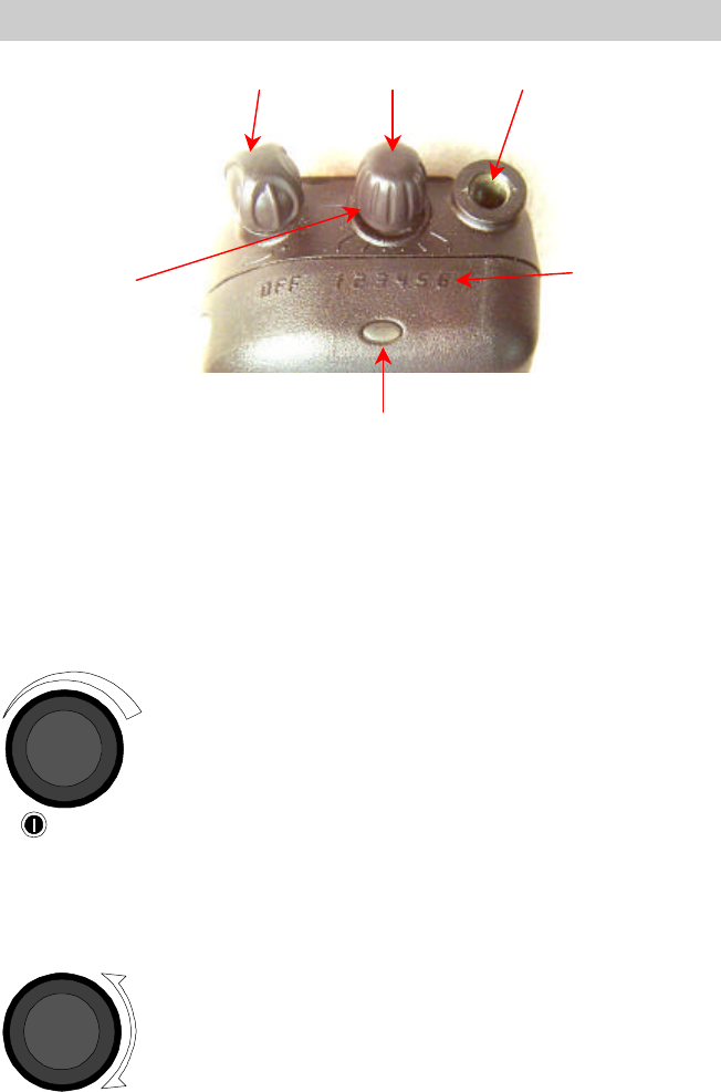
Figure 1 – Panther 300P Radio Top View
CONTROLS
All the controls for the Panther 300P mobile radio are located on the
front of the control unit and described below:
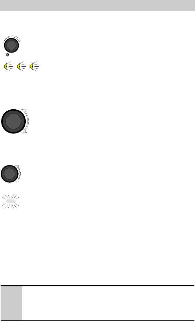
ON/OFF Volume Knob
This knob powers the radio ON/OFF and controls the
volume level of the received audio at the speaker. Rotate
the knob counterclockwise to turn the volume down.
Rotate the knob clockwise to turn the volume up. Rotate
the knob counterclockwise until it clicks and then stops,
to turn the radio OFF. When the knob is in the OFF
position, rotate the knob clockwise until the knob clicks
to turn the radio ON.
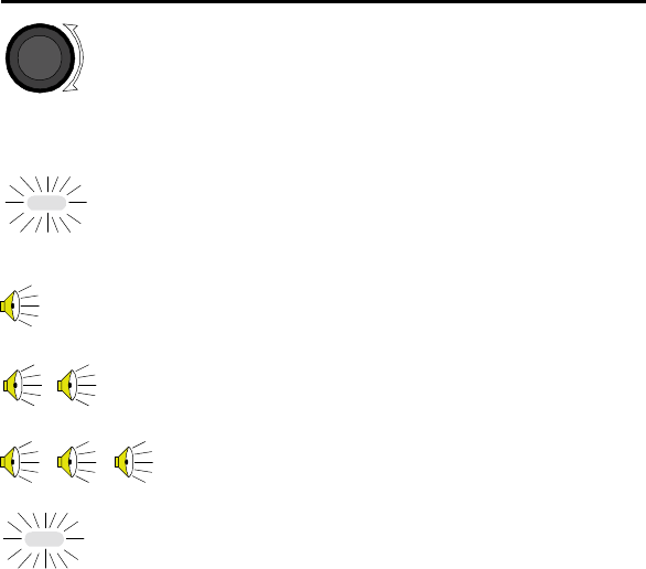
Channel Selector Knob
This 6 position rotary knob is used to select the desired
channel from a preprogrammed list of channels. Rotate
the knob clockwise to increment to the next channel in
the list. Rotate the knob counterclockwise to decrement
to the next channel in the list.
Tx/Busy LED
On/Off Switch
Volume Control
Channel Selector
Switch
Antenna
Connector
Channel Position
Numbers
Selected Channel
Indicator Ridge
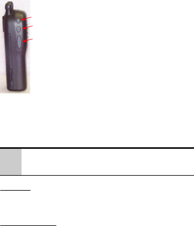
11
Option 1 Button
This button can be programmed to control one of
the radio's programmable option functions. The
default function is "Disabled".
Monitor/Clear Button
This button is assigned the Monitor/Clear
function. The function for this button is not
programmable.
PTT Button
Push To Talk button. Press to transmit a
message. Release to hear a message.
OPTION BUTTON FUNCTIONS
The following functions can be assigned to the Option 1 button.
?
In order to prevent inadvertent operation, the Option Buttons
must be pressed for at least one second before they execute
their programmed function.
Disabled
No function is assigned to the option button. When pressed, the radio
will give the Denied alert tone. This is the default for Option Button 1.
High/Low Power
The High/Low Power function controls the transmitter power. If "On",
the radio uses its longer range high power setting. If "Off", the radio
uses its battery life conserving low power setting. This is a toggle
function. If the radio is currently set for high power, pressing the option
button will change it to low power. If the radio is currently set for low
power, pressing the option button will change the radio to high power.
There will be one keypress beep when going from Low Power to High
Power. There will be two keypress beeps when going from High Power
to Low Power.
When the channel is changed or the radio is turned off and then on, the
power setting of the radio will be set according to the selected channel's
Option 1
Button
Monitor/Clear
Button
Push To Talk
(PTT Button)

Com-Net Ericsson Critical Radio Systems, Inc. 12
P.O. Box 2000
Lynchburg, Virginia 24501 MM101027V2
1-800-528-7711 (Outside USA, 804-592-7711) Printed in U.S.A.
programmed power setting. Hence, the power setting from the option
button will be overridden by the power setting of the new channel when
the channel is changed.
Monitor/Clear
The Monitor/Clear function monitors the channel for activity. While
pressed, noise squelch is disabled, Channel Guard is disabled and Type
99 is disabled.
If the channel is not busy, squelch noise will be heard. If the channel is
busy, the activity on the channel will be heard.
When the option button is released, Type 99 will be re-enabled, Channel
Guard will be re-enabled, and noise squelch will be re-enabled.
Pressing the Monitor/Clear option button can also be used to clear the
Type 99 Decoder state from Monitor mode to Selective mode after a
successful Type 99 decode.
This function is assigned to the Panther 300P's lower Option button. It
can not be changed.
Local/Distant Squelch
The Local/Distant Squelch function overrides the channel's programmed
local/distant squelch setting. This is a toggle function. If the radio is
currently using the tighter Local squelch, then pressing the Local/Distant
Squelch button will change the squelch setting to the looser Distant
setting. If the radio is currently using the Distant settings, then pressing
the option Local/Distant button will change the squelch settings to the
Local settings.
There will be one keypress beep when going from Distant to Local and
two keypress beeps when going from Local to Distant.
Type 99 On/Off
The Type 99 On/Off function controls the state of the Type 99 Decoder.
When "On", the radio is put into Selective mode. The Type 99 function
will mute receive audio until it receives a valid Type 99 call.
When "Off", the radio is always in Monitor mode.
13
The Type 99 On/Off function is a toggle function. There will be one
keypress beep when the function goes from "Off" to "On" and two
keypress beeps when the function goes from "On" to "Off".
The Type 99 On/Off function requires a Type 99 decode be programmed
on the selected channel. If this is not the case, the Type 99 On/Off
function will just do a Denied Alert Tone.
When the channel is changed or when the radio is powered up, the Type
99 decoder will change to the programmed Selective Call or Monitor
Mode default state.

Com-Net Ericsson Critical Radio Systems, Inc. 14
P.O. Box 2000
Lynchburg, Virginia 24501 MM101027V2
1-800-528-7711 (Outside USA, 804-592-7711) Printed in U.S.A.
RADIO INDICATORS
Busy / Tx Indicator
This indicator is in front of the channel selector switch
on the top of the radio. It is a three color LED. The
LED can be Red, Green, or Orange. The LED can also
be on steady or flashing depending upon the radio state.
The LED is most frequently used to indicate when the
radio is transmitting and when the channel is busy.
When the radio is transmitting, the red LED turns on
steady. When the radio channel is in use or "busy", the
green LED turns on steady.
Note that the steady green LED does not necessarily
indicate a received call if the channel has Channel Guard
or Type 99 signaling. The steady green LED only
means that the channel is in use.
A flashing green LED means the radio is on a Type 99
channel that has decoded a Type 99 call. If it is flashing
more off than on (950 milliseconds off, 50 milliseconds
on) then there is no carrier present on the displayed
channel. If the green LED is flashing more on than off
(950 milliseconds on, 50 milliseconds off), then there is
a carrier present on the displayed channel.
A flashing red LED signifies a low battery condition.
The radio battery needs to be replaced or the radio needs
to be recharged.
An orange LED usually indicates an error condition or
radio failure.
Some of these indicators can be combined. For
example, a low battery condition on a radio currently in
Type 99 Monitor mode will have flash both red and
green LED colors.
15
ALERT TONES
The PANTHER 300P radio generates a number of unique audible alert
tones or “beeps” to indicate various operating conditions. The alert tone
feature can be enabled or disabled through PC Programming. All of the
PANTHER 300P alert tones are described in the following sections:
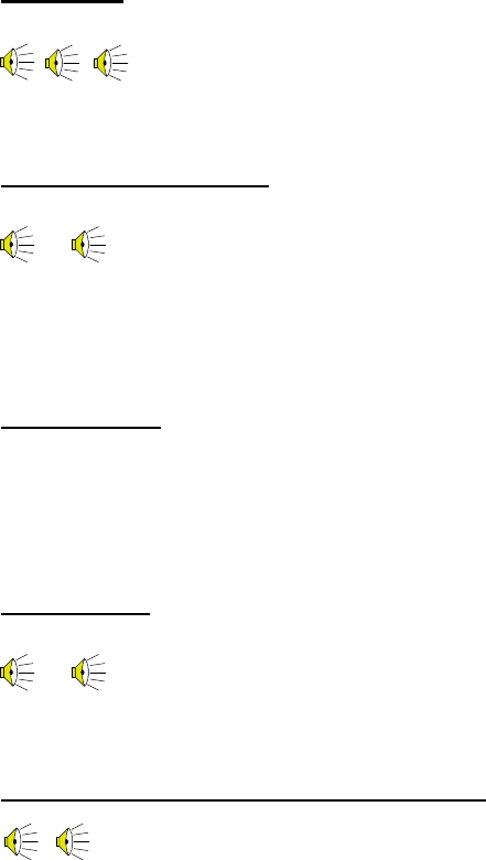
Power Up
On power up, the radio performs a diagnostic test and
then sounds three short tones to indicate the radio has
passed the diagnostic test and is ready for operation.
Carrier Control Timer
The Carrier Control Timer (CCT) is a programmable
timer that limits the amount of time the radio will allow
the user to continuously transmit. Once the time period
has expired, the radio ends the transmission and sounds
a warning tone. The warning tone will continue until the
user releases the PTT button on the microphone.
Denied Tone
A short beep that sounds when an action produces an
error or has no meaning. For example, pressing the
Type 99 On/Off option button when the displayed
channel does not have a Type 99 call defined.
Failed Tone
The Failed tone is a continuous low frequency tone that
is sounded when the radio fails its power-up self test or
when another fatal error occurs. The tone will sound
indefinitely until the radio is turned off.
Option Button Keypress That Disables
An option keypress that disables a function will sound
two short beeps.
…
…
Com-Net Ericsson Critical Radio Systems, Inc. 16
P.O. Box 2000
Lynchburg, Virginia 24501 MM101027V2
1-800-528-7711 (Outside USA, 804-592-7711) Printed in U.S.A.
Option Button Keypress That Enables
An option keypress that enables a function will sound
one short beep.
Transmitter Disabled
The Transmitter Disable Tone will sound when the PTT
is pressed but transmit operation is locked out by the
Busy Lockout Options. The warning tone will continue
until the user releases the PTT button on the
microphone. This tone will also sound when the PTT is
pressed on a receive only channel.
Type 99 Individual Call
When the radio receives an individual call, the radio will
sound one (1) short beep to alert the user of an
individual call.
Type 99 Group Call
When the radio receives a group call, the radio will
sound two (2) short beeps to indicate the radio has
received a group call.
Type 99 Super Group/Quick Call
When the radio receives a CNE super group or a
Motorola Quick Call, the radio will sound three (3) short
beeps to indicate the radio has received a super group or
Quick Call.
Synthesizer Unlock
If the synthesizer is unable to load and lock on the
channel, an alert tone will sound until the synthesizer
locks on the channel.
…
…
17
BASIC OPERATION
TURNING THE RADIO ON
From the OFF position, rotate the ON/OFF Volume
knob clockwise until the knob clicks. The radio
performs a diagnostic test and then sounds three short
tones to indicate the radio has passed the diagnostic test
and is ready for operation. The radio will be on the
channel selected by the Frequency Select Switch.
SELECTING OR CHANGING CHANNELS
Rotate the Channel Selector Knob clockwise or
counterclockwise until the raised rib on the channel
select switch aligns with the desired channel number on
the radio's body.
TRANSMITTING A BASIC CALL
1. Make sure the radio is ON. Select the desired
system and channel as described in the previous
sections.
2. Observe the TX/RX indicator for any activity on the
channel..
3. Press and hold the Monitor/Clear button for at
least l second to monitor the channel for activity.
Noise will be heard if there is no activity on the
channel. This will also help in setting the volume
level to the desired level.
4. Holding the radio approximately 2 inches from your
mouth, press the PTT button on the side of the
microphone and speak in the microphone.
?
Always speak in a normal tone of voice. Hold the radio in
your hand and approximately two (2) inches from your mouth.
Shouting will degrade your transmission, so do not speak any
louder than normal.

Com-Net Ericsson Critical Radio Systems, Inc. 18
P.O. Box 2000
Lynchburg, Virginia 24501 MM101027V2
1-800-528-7711 (Outside USA, 804-592-7711) Printed in U.S.A.
5. When you have finished speaking, release the PTT
button and wait for a reply.
CHANNEL GUARD
Channel Guard is a method of reducing "channel chatter" by equipping
receivers with a device which only allows calls with the correct signaling
to be heard by the user. Channel Guard is defined in the radio
personality.
The radio will always transmit with Channel Guard unless the channel is
programmed without Channel Guard.
Channel Guard Monitor Function
1) Observe the TX/RX indicator for any activity on the
channel.
2) Press the Monitor/Clear option button for at least 1
second.

19
SELECTIVE SIGNALING
Selective signaling is a method in conventional radio systems for
controlling the muting and unmuting of the receive audio. This allows
the radio operator or dispatcher to selectively call an individual radio or
group of radios. The PANTHER 300P radio supports selective signaling
in Type 99.
q In a selective signaling environment, the PANTHER 300P radio
operates in one of two states, Monitor mode or Selective Call mode.
In the monitor mode, the decoder's muting of the receive audio amp
is turned OFF and the user hears all calls on the channel.
In the selective mode, decoder is turned ON and only calls intended
for the user will be heard.
q Selective signaling operates with or without Channel Guard.
q If Channel Guard is enabled, the radio can be programmed with an
"And" or an "Or" option. If the "And" option is programmed, the
user will only hear calls with the correct selective signaling and
correct Channel Guard.
If the "Or" option is programmed, the user will hear calls with the
correct selective signaling as well as calls with the correct Channel
Guard. Calls with the correct Channel Guard do not have to have the
correct selective signaling to be heard.
q When the radio is in the selective mode and the radio receives a
selective call, the radio switches to the monitor mode and the
Tx/Busy LED flashes green. The Tx/Busy LED always flashes
green when the radio is in the monitor mode. The Tx/Busy LED is
also used to indicate a carrier on the channel. This combination is
shown below.
Monitor mode Without Carrier On
Off
Monitor mode With Carrier On
Off
Com-Net Ericsson Critical Radio Systems, Inc. 20
P.O. Box 2000
Lynchburg, Virginia 24501 MM101027V2
1-800-528-7711 (Outside USA, 804-592-7711) Printed in U.S.A.
TYPE 99 OPERATION
Type 99 is Com-Net Ericsson’s proprietary method for in-band, two-tone
sequential signaling. It is a conventional signaling protocol used to
control the muting and unmuting of a radio. This signaling is commonly
used for selective calling of individual units or groups of units in a
conventional system. Type 99 is typically used in paging operations,
where a dispatcher is able to select which radio or radios are to be
selectively called.
If Type 99 has been setup, the radio can decode individual, group and
supergroup paging calls. When the radio decodes an appropriate Type
99 decode sequence, an alert sounds, the Tx/Busy LED flashes green and
the radio enters the monitor mode.
Receiving An Individual, Group, or Supergroup Call
1. Select the proper system and channel as described in
the Basic Operation on page 17.
2. When the radio receives a selective call:
Ø The green TX/RX indicator will turn ON to
indicate the radio is receiving a carrier.
Ø For an individual call, a single ½ second tone
will sound to indicate the call is an individual
call.
For a group call, two short tones will sound to
indicate the call is a group call.
For a supergroup call, three short tones will
sound to indicate the call is a supergroup call.
Ø The radio switches to the monitor mode and the
Tx/Busy LED flashes green.
3. To respond to the call, hold the radio approximately
2 inches from your mouth, press the PTT button on
the side of the microphone and speak in the
microphone.

21
Resetting Type 99 After A Call
When a Type 99 call is decoded, the radio enters Monitor mode. The
Type 99 decoder will now operate in the background. If the radio is
called again, the Type 99 decoder will decode it and sound the call's alert
tone. But the decoder will no longer mute the audio. All traffic on the
channel will now be heard. (If the channel has Channel Guard, only the
traffic with the radio's Channel Guard tone will be heard.)
In order for the Type 99 decoder to mute the audio, it must be "Reset".
There are several methods of doing this.
1. Press the Monitor/Clear button.
2. Press the Type 99 On/Off button.
3. Allow an optional "Auto-Reset" timer to reset the
Type 99 decoder. This is a programmable option.
The time is also programmable between twelve
seconds and three minutes.
PROGRAMMABLE PTT FUNCTIONS
Channel Busy Lockout
The radio may be programmed to deny the use of the transmitter when
the channel is busy. This keeps another radio from interrupting a
message that is in progress. This is called Channel Busy Lockout.
If the PTT switch is pressed while the Busy/Tx LED is on, the radio will
sound an alert tone until the PTT is released.
Channel Guard Channel Busy Lockout
The radio may be programmed to deny the use of the transmitter when
the channel is busy with another Channel Guard tone. The radio will
transmit when the channel is busy with the radio's Channel Guard tone.
This is called Channel Guard Channel Busy Lockout.
If the PTT switch is pressed while the Busy/Tx LED is on and the radio
is muted because of an incorrect Channel Guard tone, the radio will
sound an alert tone until the PTT is released.
This option minimizes interference on repeater systems but also allows a
radio to transmit during the repeater dropout timer.

Com-Net Ericsson Critical Radio Systems, Inc. 22
P.O. Box 2000
Lynchburg, Virginia 24501 MM101027V2
1-800-528-7711 (Outside USA, 804-592-7711) Printed in U.S.A.
Type 99 Disable After PTT
The radio can be programmed to automatically disable the Type 99
decoder after a transmission. This is to allow for a reply to the
transmission.
The Type 99 decoder may then be reset by pressing the Monitor/Clear
button or may be programmed for an Auto-Reset time.
BATTERY OPERATION
Removing The Battery
(Need graphic showing battery removal !)
1. Turn off the radio.
2. Hold the radio with the rear facing up and the
bottom of the radio facing away from you.
3. Press the latch at the bottom of the radio toward the
top of the radio and rotate the battery outward, away
from the radio body.
Attaching The Battery
(Need graphic showing battery attachment!)
1. Verify that the radio power switch is off.
2. Hold the radio body in one hand with the rear facing
up and the bottom facing away from you. Hold the
battery such that the rear of the battery is facing up
and the latch is facing toward the rear of the radio
with the other hand.
3. Insert the battery into the rear of the radio such that
the tongue on the front of the battery engages the
groove in the front of the radio.
4. Rotate the battery down into the radio body. The
latch at the rear of the battery should engage with a
distinct click.

23
5. Verify the battery is securely latched to the radio.
6. Turn on the radio.
Low Battery Detection And Operation
The Panther 300P radio constantly monitors the battery's state of charge.
When the battery capacity is getting low, the radio will sound a Low
Battery Alert Tone. The Tx/Busy LED will begin flashing red. When
this occurs, the user should recharge the battery.
The radio may be programmed to sound just one low battery alert tone
when a low battery is sensed or may be programmed to sound the low
battery alert tone once a minute while the battery is low.
The Tx/Busy LED will always be flashing red when there is a low
battery. This low battery indication will be mixed with the other uses of
the LED. For example, a radio with its Type 99 decoder in Monitor
mode will flash red and then flash green. An exception to this is while
transmitting. The Tx/Busy LED will be on steady red whenever the
transmitter is operating.
The Panther 300P also monitors the battery voltage while transmitting.
If the battery level drops below the level needed to operate the
transmitter, the radio will stop transmitting, display the flashing red low
battery warning on the Tx/Busy LED, and sound an alert tone until the
PTT switch is released.
The Panther 300P is not capable of turning itself off when the battery
level falls below that required for the radio to operate. As a result, it is
possible to excessively discharge the battery. "Forgetting to turn the
radio off" and deeply discharging the battery will reduce battery capacity
and battery life.
Battery Error
If the radio senses a problem with the battery, it will display a "Battery
Error" warning. The Tx/Busy LED will flash orange unless the radio is
transmitting. There will be a "Battery Error" alert tone every ten seconds
while the Battery Error exists.
The Tx/Busy LED's flashing orange display will be incorporated with
the other uses of the Tx/Busy LED. For example, when the radio's Type
99 decoder is in Monitor mode, the Tx/Busy LED will be flash orange
and then flash green.

Com-Net Ericsson Critical Radio Systems, Inc. 24
P.O. Box 2000
Lynchburg, Virginia 24501 MM101027V2
1-800-528-7711 (Outside USA, 804-592-7711) Printed in U.S.A.
The Battery Error condition is best avoided by only using genuine Com-
Net Ericsson approved batteries.
Charge The Battery Before Using
Insert the radio into the slot on the charger and ensure that the
ON/OFF/VOLUME control is in the OFF position. Connect charger to a
120 VAC outlet. (An optional 230 VAC charger may be needed for
international applications.) The battery is fully charged when the
charger LED indicator changes from red to green.
Recharging The Battery
Recharge the battery when the radio battery indicator shows "Low
Battery”. When charging a battery pack that is attached to a radio,
always turn the radio OFF to ensure a full charge. For specific
instructions, refer the applicable charger Operator's Manual. Charging in
non-Com-Net Ericsson equipment may lead to battery damage and void
the battery warranty.
Conditioning The Battery
Batteries which have been stored (charged or discharged) will generally
not be capable of full capacity until the batteries have been fully cycled
two or three times. (Charging the battery in an Com-Net Ericsson
charger and then discharging the battery pack with the radio until low
battery is indicated, is considered one cycle.)

25
Battery Care & Maintenance
• Your charger is intended for indoor use only. Keep
the charger and/or wall cube dry. Do Not use in or
near water.
• Never let the battery contacts touch metal objects
that could short-circuit the contacts. For example,
keys or coins in your pocket.
• Do Not disassemble a battery.
• Do Not dispose of a battery in a fire.
• Use only the supplied or Com-Net Ericsson
specified batteries and chargers.
• Turn the radio off when not in use. Overly
discharging the battery will reduce battery capacity
and battery life.
• Do not overcharge the battery. A battery should not
be kept in a charger for over 24 hours.
Overcharging batteries will reduce battery capacity
and battery life.
• Periodically condition your battery for improved
battery capacity and performance.
Battery Recycling
The product that you have purchased contains a
rechargeable, recyclable battery. At the end of its useful
life, under various state and local laws, it may be illegal
to dispose of this battery into the municipal waste
stream. Check with your local solid waste officials for
details in your area for recycling options or proper
disposal. Call Toll Free 1-800-8- BATTERY or go to
the Rechargeable Battery Recycling Corporation website
www.rbrc.com for additional information.