HARRIS TR-0004-A Panther 300M VHF (150-174 MHz) User Manual Installation Manual
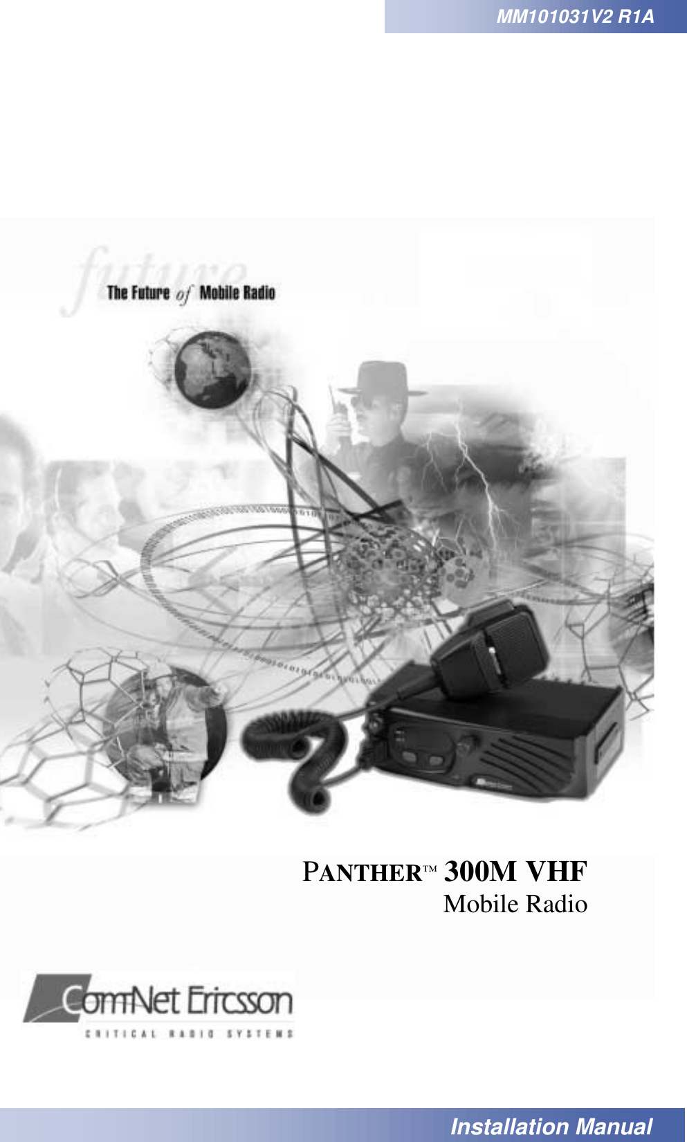
HARRIS CORPORATION Panther 300M VHF (150-174 MHz) Installation Manual
HARRIS >
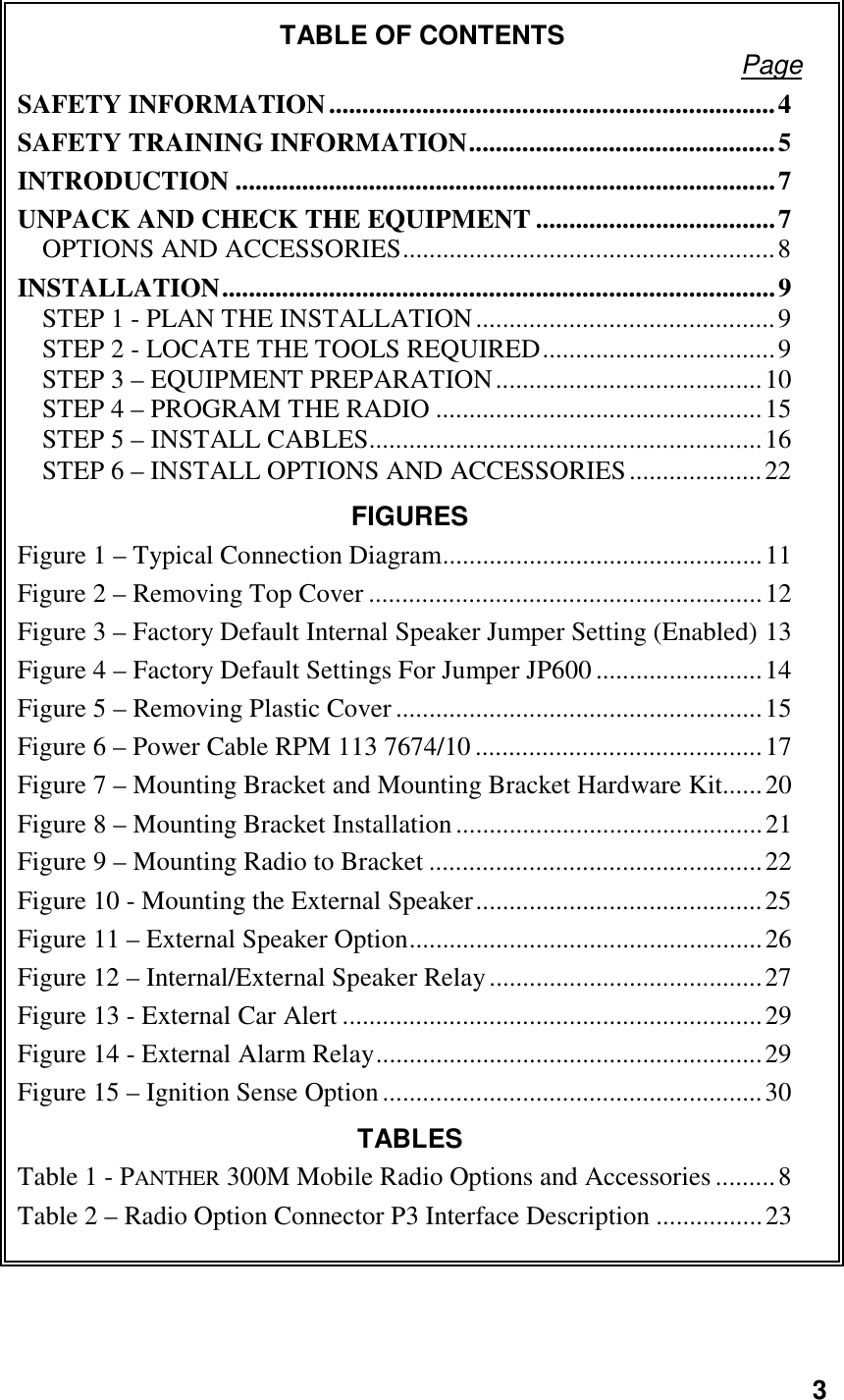
Contents
- 1. Installation Manual
- 2. Operational Manual
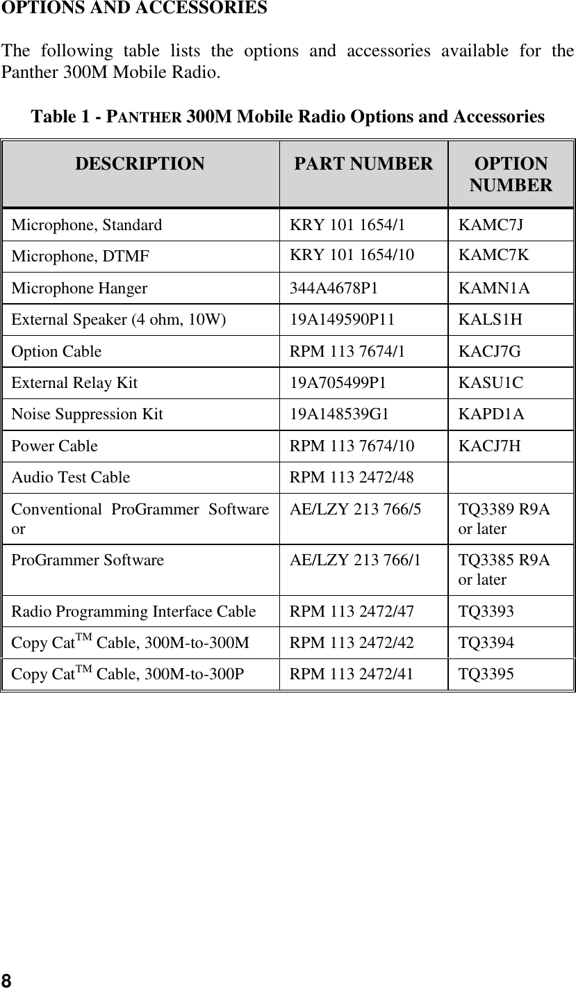
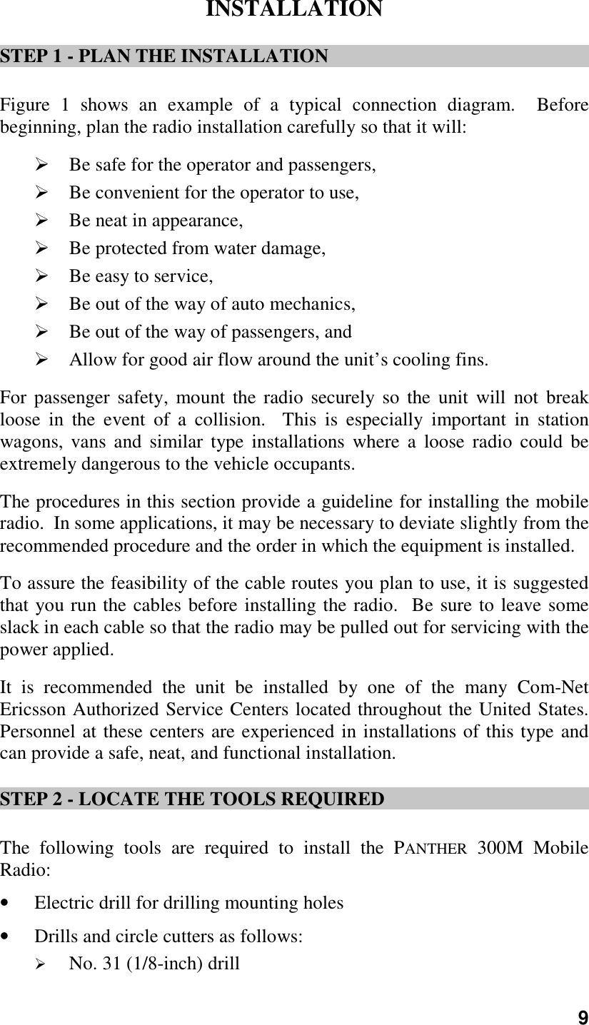
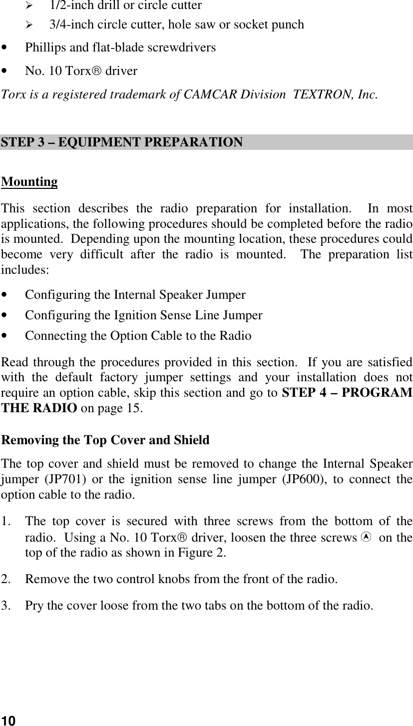
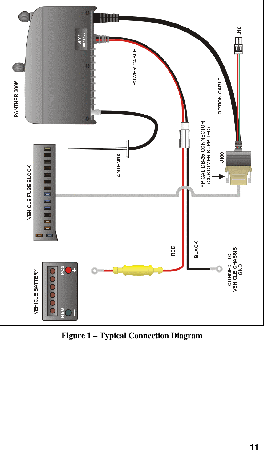
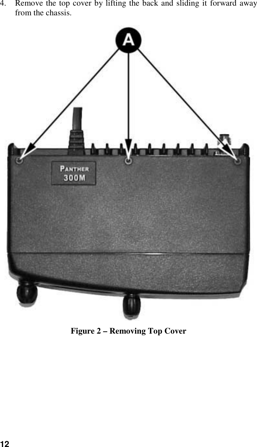
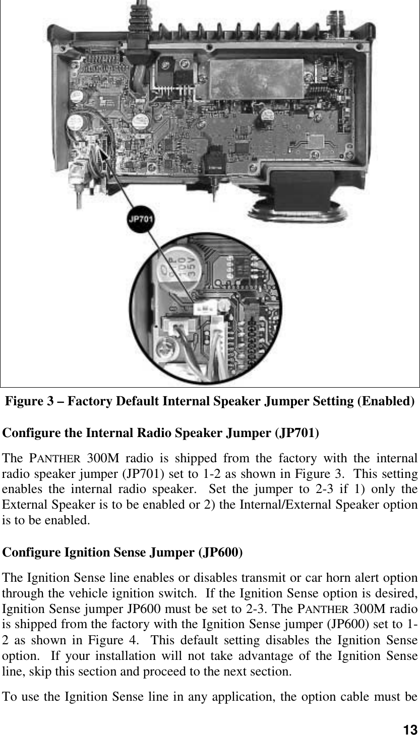
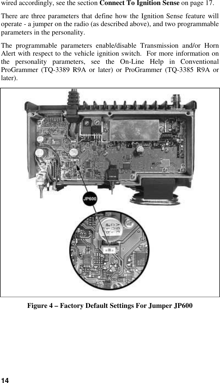
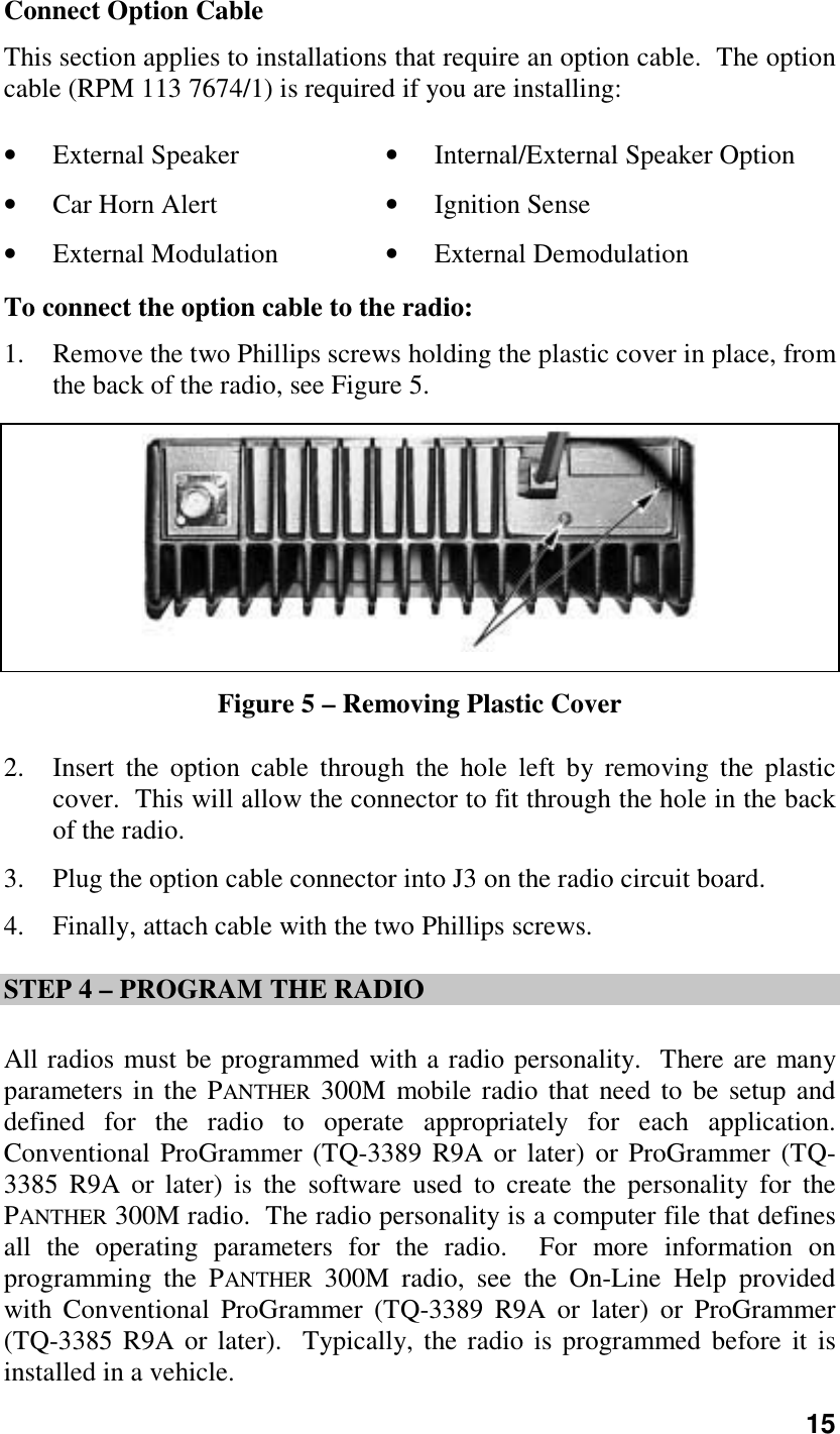
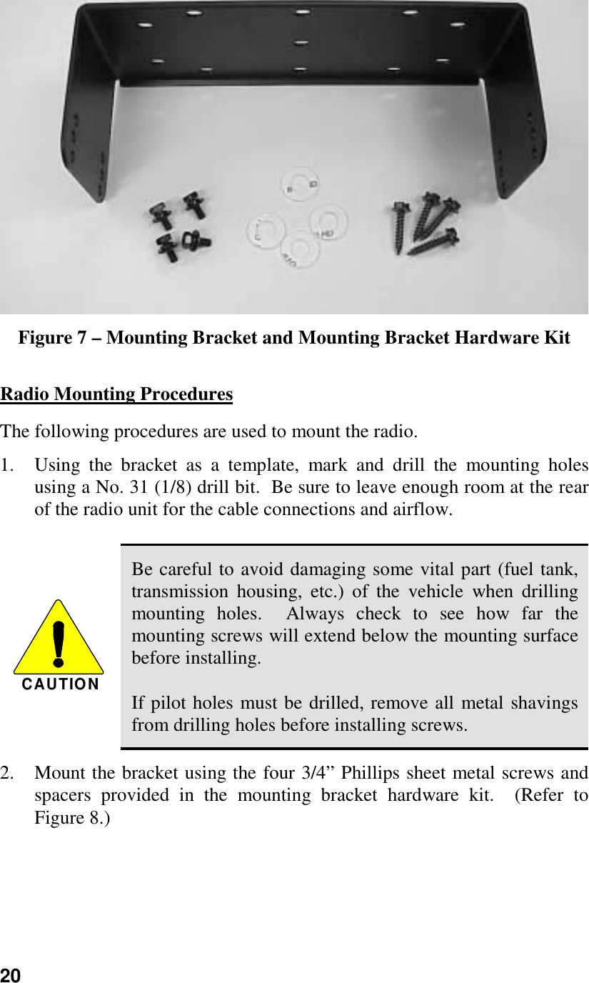
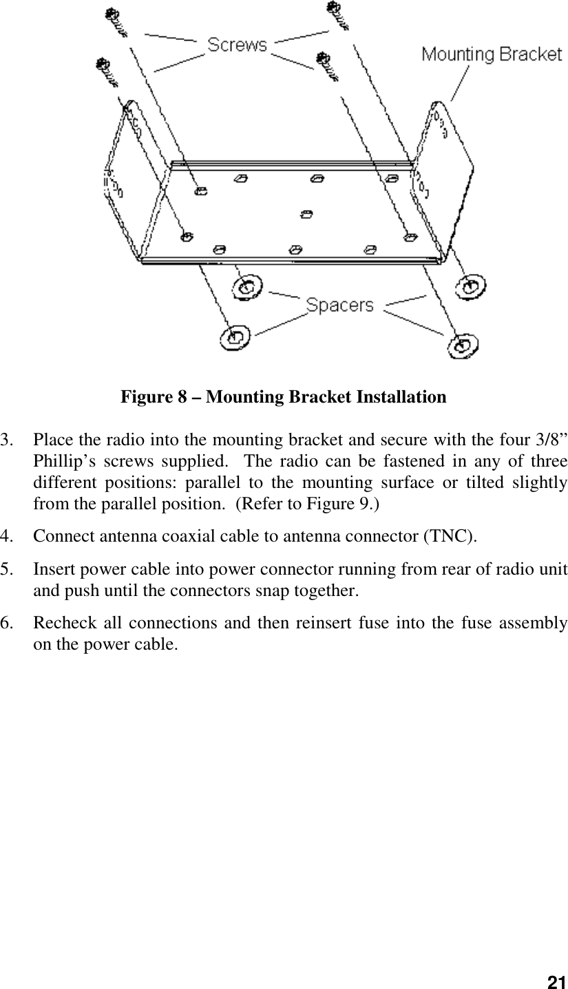
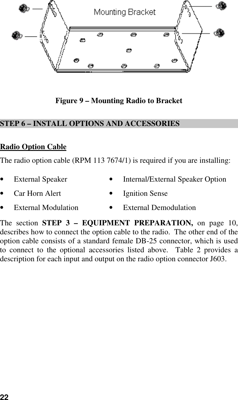
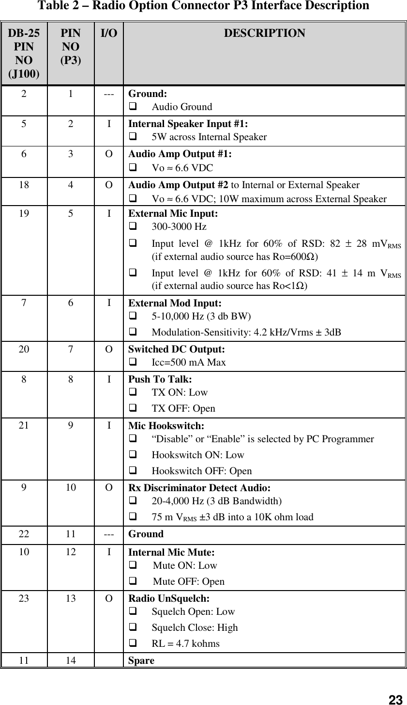
Installation Manual