HARRIS TR-0015-E UHF-FM Hand Held Transceiver User Manual Part 90
HARRIS CORPORATION UHF-FM Hand Held Transceiver Part 90
HARRIS >
Manual

Rhein Tech Laboratories Client: M/A COM, Inc.
360 Herndon Parkway Model: P7100(IP) UHF Radio
Suite 1400 Standards: FCC Part 90/IC RSS-119
Herndon, VA 20170 Report Number: 2002224
http://www.rheintech.com Date: January 21, 2003
49 of 53
APPENDIX G: MANUAL
Please see the following pages.
`Operators Manual
MM101332V1 R2A
P7100IP Series
Portable Radios

2
TABLE OF CONTENTS
Page
SAFETY TRAINING INFORMATION ........................................... 3
OPERATING RULES AND REGULATIONS ................................ 7
OPERATING TIPS............................................................................ 9
BATTERY DISPOSAL ................................................................... 13
SCOPE OF THIS MANUAL .......................................................... 14
OPTIONS AND ACCESSORIES ................................................... 15
USER INTERFACE ........................................................................18
STATUS MESSAGES..................................................................... 25
BASIC OPERATION ...................................................................... 28
TRANSMITTING A CALL IN TRUNKED MODE...................... 34
RECEIVING A CALL IN TRUNKED MODE .............................. 35
CONVENTIONAL OPERATION .................................................. 36
OPERATION FOLLOWING WATER CONTACT....................... 37
CHANGING THE BATTERY PACK ............................................39
BATTERY WARRANTY ............................................................... 41
WARRANTY................................................................................... 42
The software contained in this device is copyrighted by M/A-COM, Inc. Unpublished rights are
reserved under the copyright laws of the United States.
NOTICE!
This manual is published by M/A-COM, Inc., without any warranty. Improvements and
changes to this manual necessitated by typographical errors, inaccuracies of current
information, or improvements to programs and/or equipment, may be made by M/A-
COM, Inc., at any time and without notice. Such changes will be incorporated into new
editions of this manual. No part of this manual may be reproduced or transmitted in any
form or by any means, electronic or mechanical, including photocopying and recording,
for any purpose, without the express written permission of M/A-COM, Inc.
Copyright © 2003 M/A-COM, Inc. All rights reserved.

3
SAFETY TRAINING INFORMATION
WARNING
The M/A-COM P7100IP portable radio
generates RF electromagnetic energy
during transmit mode. This radio is
designed for and classified as
“Occupational Use Only,” meaning it
must be used only during the course of employment
by individuals aware of the hazards and the ways to
minimize such hazards. This radio is NOT intended for
use by the “General Population” in an uncontrolled
environment.
The P7100IP portable radio has been tested and complies
with the FCC RF exposure limits for “Occupational Use
Only.” In addition, this M/A-COM radio complies with the
following Standards and Guidelines with regard to RF
energy and electromagnetic energy levels and evaluation
of such levels for exposure to humans:
• FCC OET Bulletin 65 Edition 97-01 Supplement C,
Evaluating Compliance with FCC Guidelines for
Human Exposure to Radio Frequency Electromagnetic
Fields.
• American National Standards Institute (C95.1 – 1992),
IEEE Standard for Safety Levels with Respect to
Human Exposure to Radio Frequency Electromagnetic
Fields, 3 kHz to 300 GHz.

4
• American National Standards Institute (C95.3 – 1992),
IEEE Recommended Practice for the Measurement of
Potentially Hazardous Electromagnetic Fields – RF
and Microwave.
RF EXPOSURE GUIDELINES
CAUTION
To ensure that exposure to RF
electromagnetic energy is within the FCC
allowable limits for occupational use,
always adhere to the following
guidelines:
• DO NOT operate the radio without a proper antenna
attached, as this may damage the radio and may also
cause the FCC RF exposure limits to be exceeded. A
proper antenna is the antenna supplied with this radio
by M/A-COM or an antenna specifically authorized by
M/A-COM for use with this radio. (Refer to Table 2 –
Options and Accessories.)
• DO NOT transmit for more than 50% of total radio use
time (“50% duty cycle”). Transmitting more than 50%
of the time can cause FCC RF exposure compliance
requirements to be exceeded. The radio is
transmitting when the “TX” indicator appears in the
display. The radio will transmit by pressing the “PTT”
button.
5
• Always transmit using low power (refer to High/Low
Power Adjustment section) when possible. In addition
to conserving battery charge, low power can reduce
RF exposure.
• ALWAYS use M/A-COM authorized accessories
(antennas, batteries, belt clips, speaker/mics, etc).
Use of unauthorized accessories may cause the FCC
Occupational/Controlled Exposure RF compliance
requirements to be exceeded. (Refer to Table 2 –
Options and Accessories.)
• ALWAYS keep the device and its antenna at least 2
cm (0.8 inches) from the body and at least 5 cm (2
inches) from the face when transmitting to ensure FCC
RF exposure compliance requirements are not
exceeded. This radio has been tested for RF exposure
compliance at the distances listed in Table 1.
However, to provide the recipients of your
transmission the best sound quality, hold the antenna
at least 5 cm (2 inches) from mouth, and slightly off to
one side.

6
Table 1 - RF Exposure Compliance Testing
Distances
TESTED DISTANCES
(worst case scenario)
RADIO FREQUENCY
Body Face
800MHz 1.6 cm 2.5 cm
VHF (136-174MHz) 1.1 cm 2.5 cm
UHF-H (450-512MHz) 1.1 cm 2.5 cm
The information in this section provides the information
needed to make the user aware of a RF exposure, and
what to do to assure that this radio operates within the FCC
RF exposure limits of this radio.
ELECTROMAGNETIC INTERFERENCE/COMPATIBILITY
During transmissions, this M/A-COM radio generates RF
energy that can possibly cause interference with other
devices or systems. To avoid such interference, turn off
the radio in areas where signs are posted to do so. DO
NOT operate the transmitter in areas that are sensitive to
electromagnetic radiation such as hospitals, aircraft, and
blasting sites.
7
OPERATING RULES AND REGULATIONS
Two-way FM radio systems must be operated in
accordance with the rules and regulations of the Federal
Communications Commission (FCC). As an operator of
two-way radio equipment, you must be thoroughly familiar
with the rules that apply to your particular type of radio
operation. Following these rules will help eliminate
confusion and will assure the most efficient use of existing
radio channels. This will provide a smooth operating radio
network.
When using the radio, remember these rules:
1. It is a violation of FCC rules to interrupt any distress or
emergency message. As the radio operates in much
the same way as a telephone "party line" when in
conventional mode, always listen and/or observe the
absence of the “busy” display (refer to Table 3 –
Display for display character) to make sure that the
line is clear before sending any messages. If someone
is sending an emergency message, such as reporting
a fire or asking for help in an accident, KEEP OFF
THE AIR! Emergency calls have priority over all other
messages.
2. Use of profane or obscene language is prohibited by
Federal Law.
3. It is against the law to send false call letters or a false
distress or emergency message.
8
4. The FCC requires that conversations be brief and
confined to business. To save time, use coded
messages whenever possible.
5. Using the radio to send personal messages (except in
an emergency) is a violation of FCC rules. Send only
those messages essential for the business operation.
6. It is against Federal Law to repeat or otherwise make
known anything overheard on the radio. Conversations
between others sharing your channel must be
regarded as confidential.
9
OPERATING TIPS
Antenna location and condition are important when
operating a portable radio. Operating the radio in low lying
areas or terrain, under power lines or bridges, inside of a
vehicle or in a metal framed building can severely reduce
the range of the unit. Mountains can also reduce the range
of the unit.
In areas where transmission or reception is poor, some
improvement may be obtained by ensuring that the
antenna is vertical. Moving a few yards in another direction
or moving to a higher elevation may also improve
communications. Vehicular operation can be aided with the
use of an externally mounted antenna.
Battery condition is another important factor in the trouble
free operation of a portable radio. Always properly charge
the batteries.
EFFICIENT RADIO OPERATION
Hold the portable radio approximately three inches from
your mouth and speak into the microphone at a normal
voice level.
Keep the antenna in a vertical position when receiving or
transmitting a message.
Do not hold the antenna when receiving a message and,
especially, do not hold when transmitting a message.
10
WARNING
Do NOT hold onto the antenna when
transmitting!
Antenna Care and Replacement
WARNING
Always keep the antenna at least 0.8 inches
(2 cm.) away from the body and 2 inches (5
cm.) from the face when transmitting to
ensure FCC RF exposure compliance
requirements are not exceeded.
WARNING
Do not use the portable radio with a damaged
or missing antenna. A minor burn may result
if a damaged antenna comes into contact
with the skin. Replace a damaged antenna
immediately. Operating a portable radio with
the antenna missing could cause personal
injury, damage the radio, and may violate
FCC regulations.
11
WARNING
Use only the supplied or approved antenna.
Unauthorized antennas, modifications or
attachments could cause damage to the radio
unit and may violate FCC regulations. (Refer
to Table 2 – Options and Accessories.)
Electronic Devices
CAUTION
RF energy from portable radios may affect
some electronic equipment. Most modern
electronic equipment in cars, hospitals,
homes, etc. are shielded from RF energy.
However, in areas in which you are instructed
to turn off two-way radio equipment, always
observe the rules. If in doubt, turn it off!
Aircraft
WARNING
Always turn off a portable radio before
boarding any aircraft!
• Use it on the ground only with crew
permission.
• DO NOT use while in-flight!!
12
Blasting Areas
WARNING
Turn two-way radios OFF when in a "blasting
area" or in areas posted "turn off two-way
radio." Remote control RF devices are used
by some construction crews to detonate
explosives.
Potentially Explosive Atmospheres
WARNING
Areas with potentially explosive atmosphere
are often, but not always, clearly marked.
These may be fueling areas, such as gas
stations, fuel or chemical transfer or storage
facilities, and areas where the air contains
chemicals or particles, such as grain, dust, or
metal powders.
Sparks in such areas could cause an
explosion or fire resulting in bodily injury or
even death.
Turn OFF two-way radios when in any area
with a potentially explosive atmosphere. It is
rare, but not impossible that a radio or its
accessories could generate sparks.
13
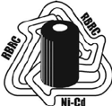
BATTERY DISPOSAL
The P7100IP series portable radios use rechargeable,
recyclable Nickel Cadmium (NiCd) or Nickel Metal Hydride
(NiMH) batteries.
NICKEL CADMIUM BATTERY
At the end of its useful life, under
various state and local laws, it may be
illegal to dispose of Nickel Cadmium
batteries into the municipal waste
stream. Check with local solid waste
officials for recycling options and proper
disposal. Call Toll Free 1-800-8BATTERY for information
and/or procedures for returning rechargeable batteries in
your state.
NICKEL METAL HYDRIDE BATTERY
There are no special requirements concerning the disposal
of NiMH batteries. Batteries can be recycled. Call Toll
Free 1-800-8BATTERY for information.
14
SCOPE OF THIS MANUAL
This manual describes the basic functions and operation of
the P7100IP series portable radios. For further detail about
features and operation refer to the appropriate
Maintenance Manual or contact the System Administrator.
WATER RESISTANCE
The P7100IP series portable radios operate reliably even
under adverse conditions. These radios meet MIL-STD-
810F specifications for driven rain, humidity, and salt fog.

15
OPTIONS AND ACCESSORIES
Table 2 lists options and accessories tested for use with
the P7100IP series portable radios. Items for use with a
specific band split are noted.
Refer to the maintenance manual or to M/A-COM’s
Products and Services Catalog for a complete list of
options and accessories that includes those items that do
not adversely affect the RF energy exposure.
WARNING
Always use M/A-COM authorized
accessories (antennas, batteries, belt clips,
speaker/mics, etc). Use of unauthorized
accessories may cause the FCC
Occupational/Controlled Exposure RF
compliance requirements to be exceeded.
Refer to Table 2 – Options and Accessories.)
CAUTION
Always use the correct options and
accessories (battery, antenna, speaker/mic,
etc.) for the radio. Immersion rated options
must be used with an immersion rated radio.
Intrinsically safe options must be used with
intrinsically safe radios. (Refer to Table 2 –
Options and Accessories.)

16
Table 2 – Options and Accessories
DESCRIPTION PART NUMBER
ANTENNAS
Antenna (136-151 MHz) KRE 101 1219/1
Antenna (150-162 MHz) KRE 101 1219/2
Antenna (162-174 MHz) KRE 101 1219/3
Antenna, Spring Whip (450-470 MHz) KRE 101 1219/12
Antenna, Spring Whip (470-512 MHz) KRE 101 1219/13
Antenna, Quarter Wave (450-512 MHz) KRE 101 1223/12
Flexible Gain Antenna (800 MHz) KRE 101 1506/1
Whip Antenna (800 MHz) KRE 101 1223/01
BATTERIES (IMMERSION-RATED)
7.5V Nickel Cadmium (NiCd) Battery BKB 191 210/3
7.5V Nickel Metal Hydride (NiMH)
Battery
BKB 191 210/4
7.5V NiCd Battery-Intrinsically Safe <IS> BKB 191 210/5
7.5V NiMH Battery-Intrinsically Safe <IS> BKB 191 210/6
BATTERIES (DRIVEN RAIN)
7.5V NiCd Battery BKB 191 210/23
7.5V NiMH Battery BKB 191 210/24
7.5V NiCd Battery - <IS> BKB 191 210/25
7.5V NiMH Battery - <IS> BKB 191 210/26
MISCELLANEOUS ACCESSORIES
Speaker Microphone Antenna Version
Plus
KRY 101 1617/84
or
KRY 101 1617/184

17
DESCRIPTION PART NUMBER
Speaker Microphone KRY 101 1617/83
or
KRY 101 1617/183
Metal Belt Clip KRY 101 1647/1
Belt Loop with Swivel (VHF and UHF-H) KRY 101 1609/1
Leather Belt Loop & Swivel (800 MHz) 19B226627G2 &
19B233243G3
Leather Case (Belt Loop type) KRY 101 1638/1
Leather Case with Swivel & Belt Loop
(VHF and UHF-H)
KRY 101 1639/1
Nylon Case with Swivel & Belt Loop KRY 101 1648/1 &
19B226627G2
Nylon T-Strap KRY 101 1656/1
18
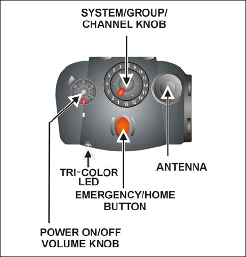
USER INTERFACE
Figure 1 – Top View
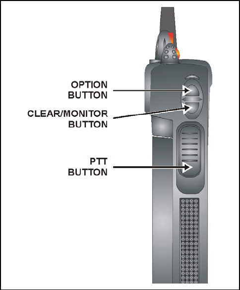
19
Figure 2 – Side View
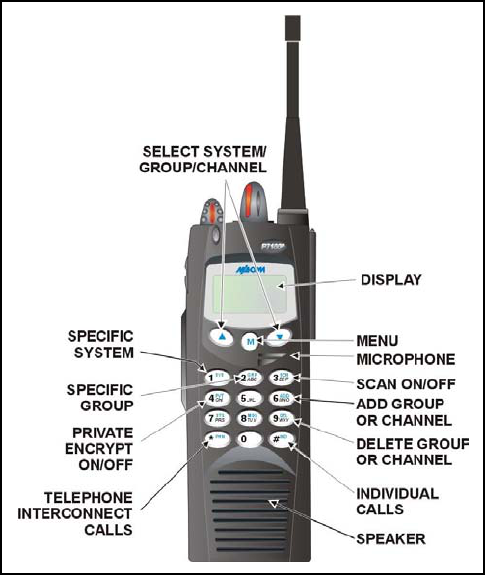
20
Figure 3 – System Model
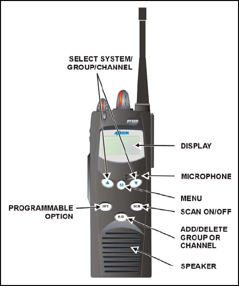
21
Figure 4 – Scan Model
22
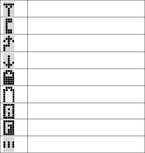
Table 3 – Display Icons
Icon Descriptions
Steady – “Busy” transmitting or receiving
Flashing – call queued
Steady – special call mode (individual or telephone)
Steady – during all radio transmissions
Steady – transmit at low power
If icon is not visible – transmit at high power
Steady – battery charge indicator (refer to Figure 5)
Flashing – Low battery indicator (refer to Figure 5)
Steady – Analog
Steady – trunked system in Failsoft mode
Steady – group or channel in scan list
23
Steady – priority 2 group or channel
Steady – priority 1 group or channel
Steady (rotates clockwise) – scan mode enabled
If icon is not visible – scan is disabled
Steady – transmit in encrypt mode
Flashing – receiving an encrypted call
Steady – Channel Guard enabled
If icon is not visible – Channel Guard is disabled
Steady – Indicates the current channel is set up as
a Project 25 (P25) channel.
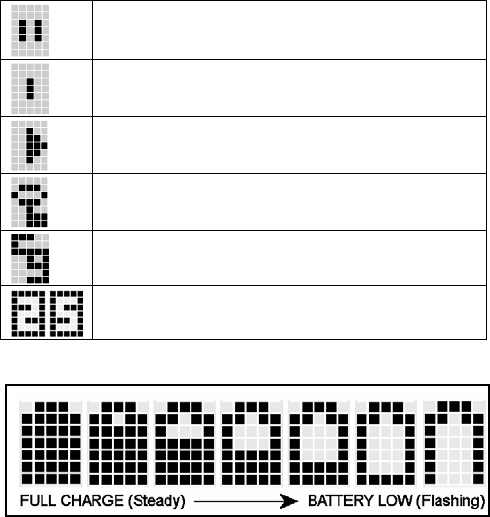
Figure 5 - Battery Charge Icons (Full Cycle)
The battery icons (as illustrated in Figure 5) indicate
approximate level only, based on battery voltage.
24
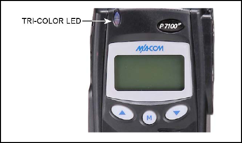
Figure 6 – Tri-Color LED
TRI-COLOR LED
The tri-color LED changes color to indicate radio status and
is visible from both the front and top of the radio. The three
colors of the LED and the status they represent are:
Green: Receiving
Red: Unencrypted transmission
Orange: Encrypted transmission

25
STATUS MESSAGES
During radio operation, various radio status messages can
be displayed. The messages are described below.
MESSAGE NAME DESCRIPTION
QUEUED Call Queued Trunked mode only. Indicates
the system has placed the call
in a request queue.
SYS BUSY System Busy Trunked mode only. Indicates
the system is busy, no channels
are currently available, the
queue is full, or an individual
call is being attempted to a
radio that is currently
transmitting.
DENIED Call Denied Trunked mode only. Indicates
the radio or talkgroup is not
authorized to operate on the
selected system and/or
talkgroup.
CC SCAN Control Channel
Scan
Trunked mode only. Indicates
the control channel is lost and
the radio has entered the
Control Channel Scan mode to
search for the control channel
(usually out of range indication).

26
MESSAGE NAME DESCRIPTION
WA SCAN Wide Area Scan Trunked mode only. Indicates
the radio has entered the Wide
Area Scan mode to search for a
new system (if enabled through
programming).
TALKARND Talkaround Conventional mode only.
Indicates the radio is operating
on conventional channels in
talkaround mode (no repeater).
SYSC ON System Scan
Features On
Trunked mode only. Indicates
the System Scan features are
enabled.
SYSC OFF System Scan
Features Off
Trunked mode only. Indicates
the System Scan features are
disabled.
LOW BATT Low Battery Battery voltage has dropped
below the point to where the
radio is no longer able to
transmit. The radio will still be
receive calls until the battery is
discharged beyond the point of
operation upon which the radio
will automatically shutdown.
RXEMER Receive
Emergency
Trunked mode only. Indicates
an emergency call is being
received. This message will be
flashing on line two.

27
MESSAGE NAME DESCRIPTION
TXEMER Transmit
Emergency
Trunked mode only. Indicates
an emergency call has been
transmitted on this radio. This
message will be flashing on line
two.
VOL=31 Volume Level Indicates the current volume
level. The volume level display
ranges from OFF (silent) to 31
(loudest).
WHC Who Has Called Trunked mode only. Indicates
an individual call has been
received, but not responded to.
The indicator turns OFF if the
individual call mode is entered,
the system is changed, or the
radio is turned off and then on
again.
UNKNOWN Unknown ID Trunked mode only. Indicates
an individual call is being
received from an unknown ID.
28
BASIC OPERATION
SYSTEM SELECT – METHOD 1 (SYSTEM)
1. Press to access system list.
2. Enter system ID number from keypad.
3. Press to select desired system.
SYSTEM SELECT – METHOD 2
Rotate System/Group/Channel knob, or
If this knob is not programmed for systems, press the
buttons to change systems.
GROUP SELECT – METHOD 1 (SYSTEM)
1. Press to access group list.
2. Press
to scroll through the list of groups.
3. Press to select desired group.
GROUP SELECT – METHOD 2
1. Rotate System/Group/Channel knob.
If this knob is not programmed for groups:
2. Press the
buttons to change groups.

29
CHANNEL SELECT
Rotate System/Group/Channel knob, or
If this knob is not programmed for channels, press the
buttons to change channels.
MODIFY SCAN LIST (SYSTEM)
1. Press to toggle scan OFF and verify is not
displayed.
2. Select group or channel.
3. Press once to remove group or channel from list.
4. Press
once to add as a normal group or channel.
Press twice to add as a Priority 2 group.
Press three times to add as a Priority 1 group.
5. Press
to re-start scanning.
MODIFY SCAN LIST (SCAN MODEL)
1. Press to toggle scan OFF and verify is not
displayed.
2. Select group or channel.
3. Press once to remove group or channel from the
list.
30
4. Press once to add as a normal group or channel.
Press twice to add as a Priority 2 group.
Press three times to add as a Priority 1 group.
5. Press
to re-start scanning.
NUISANCE DELETE (SYSTEM MODEL)
A channel can temporarily be deleted from the scan list if it
is not the currently selected channel.
1. Turn Scan ON.
2. When the radio receives a call on the channel, press
the . The channel is removed from the scan list
until the radio is power cycled.
BACKLIGHT ON/OFF
1. Press to access the menu.
2. Press to scroll through menu until
“BCKLGHT” appears.
3. Press
to select Backlight menu.
4. Press
to toggle backlight ON and OFF.
5. Press
to select new backlight setting.

31
CONTRAST ADJUST
1. Press to access the menu.
2. Press to scroll through menu until
“CONTRAST” appears.
3. Press
to select Contrast menu.
4. Press to adjust contrast setting from 1 - 4.
5. Press
to select new contrast setting.
DECLARING AN EMERGENCY
1. Press and hold the red Emergency/Home button (the
length of time is programmable; check with the system
administrator).
2. *TXEMER* will flash in the display, plus and will
be displayed. After 2-3 seconds the transmit icon
will turn off.
3. *TXEMER* and will remain until the emergency is
cleared.
4. Press the PTT and will reappear.

32
5. Release PTT when the transmission is complete.
LOCKING/UNLOCKING KEYPAD
1. Press button.
2. Within 1 second, press the Option button on the side
of the radio.
HIGH/LOW POWER ADJUSTMENT
Transmit power adjustment is possible if enabled through
programming. Within conventional systems, transmit
power is adjustable on a per channel basis. Within EDACS
trunking systems, transmit power is adjustable on a per
system basis.
There are two ways to toggle between high and low power:
Using the Menu Button:
1. Press
.
2. Using the
and keys, scroll until the cursor (>)
appears to the left of “TX POWER” in the display.
3. Press again to toggle between High and Low power.
4. “POWER = HIGH” or “POWER = LOW” will appear
momentarily on the top line of the display.

33
Using the Pre-Programmed Option Button:
5. Press the Option button. “POWER = HIGH” or
“POWER = LOW” will appear momentarily on the
top line of the display.
Table 4 - Alert Tones
NAME TONE DESCRIPTION
Call
Originate
(B) one short
mid-pitched
OK to talk after pressing the
push-to-talk button
Call
Queued
(T) one high-
pitched
Call queued for processing
Autokey (T) one mid-
pitched
Queued call received channel
assignment
System
Busy
(T) three low-
pitched
System busy or unable to
complete call
Call Denied (T) one low-
pitched
Radio is not authorized on the
system or group
Carrier
Control
Timer
(B) five high-
pitched /
one long
low-pitched
PTT depressed for maximum
length of time
Low
Battery
(B) one low-
pitched/
one short
mid-pitched
Low battery
TX Low
Battery
Alert
(B) one low-
pitched
After PTT - battery too low to
transmit
(T) = trunked mode only (B) = both trunked and conventional modes

34
TRANSMITTING A CALL IN TRUNKED MODE
GROUP CALL
1. Select desired group.
2. Press Push-To-Talk button.
3. The and icons will appear.
INDIVIDUAL CALL (SYSTEM)
1. Press to access the individual call list.
2. The icon will appear.
3. Press to scroll through individual call list or
Enter LID from keypad.
4. When the desired ID appears in the display press the
Push-To-Talk button.
5. The and icons will appear.
PHONE CALL (SYSTEM)
1. Press to access the phone call list.
2. The icon will appear.
3. Press to scroll through phone call list or Enter
number from keypad.
4. When the desired phone number appears in the
display press the Push-To-Talk button.
5. The and icons will appear.

35
RECEIVING A CALL IN TRUNKED MODE
GROUP CALLS
1. Select a group or turn scan ON and make sure group
is in scan list.
2. The group name or “GR xxxxx” will appear to indicate
a call.
PHONE CALLS
1. When the call is received, the receive audio sounds
and the display reads: *PHONE*
2. Respond by pressing PTT. If you do not respond,
radio will continue to ring to indicate an incoming call.
INDIVIDUAL CALLS
1. When the call is received, the receive audio sounds
and the display reads : ID xxxxx
*INDV*
2. Respond by pressing PTT. If you do not respond,
radio will continue to ring to indicate an incoming call.
3. If the call is cleared with no response, the radio will
store Who Has Called and display: *WHC*
4. Press the
key to display the ID.
5. Press the Push-To-Talk button to return the call or
press the Clear/Monitor button to clear the *WHC*.

36
CONVENTIONAL OPERATION
RECEIVING A CALL
1. Select desired conventional system and channel or
turn scan ON and make sure desired channel is in
scan list.
2. When the radio receives a call, the radio will unmute
and the channel name will appear in the display.
SENDING A CALL
1. Select desired system and channel.
2. Ensure the channel is not busy by pressing the
Monitor/Clear button momentarily. If audio is heard
or if the icon is on, the channel is busy.
3. When sure that the channel is not busy, press the
Push-To-Talk button and speak into the microphone.
37
OPERATION FOLLOWING WATER CONTACT
If the P7100IP model radio has been immersed in water or if
the microphone air path or speaker grill become clogged
with water, follow instructions under “Radio Microphone
and Radio Speaker” to assure the highest quality
transmitted and received messages.
RADIO MICROPHONE
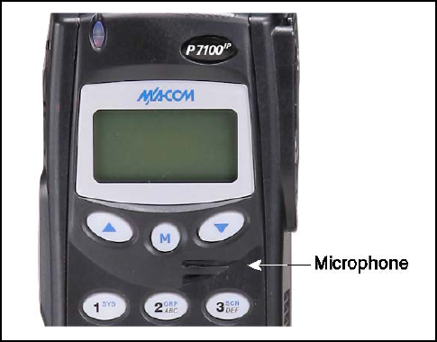
In the event the P7100IP microphone air path becomes
clogged with water, blow two quick successive breaths of
air directly into the radio microphone air hole. Refer to
Figure 7. This will help to clear any water trapped in the
microphone air path and allow the microphone to function
properly.
38
Figure 7 – Radio Microphone
RADIO SPEAKER
To assure the user receives the highest quality receive
audio possible after the radio has contacted water or been
immersed, it may be necessary to clear excess water from
the speaker cavity and grill. The speaker grill has been
designed for easy drainage. To facilitate maximum
drainage and the highest quality speaker output, shake the
radio vigorously with speaker grill face down.
39
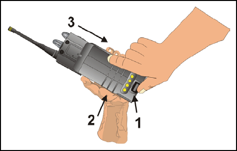
CHANGING THE BATTERY PACK
REMOVING THE BATTERY PACK
Make sure the power to the radio is turned OFF.
1. Press the latch at the bottom of the battery pack.
2. Lift the battery pack from the bottom.
3. Remove the battery pack from the radio.
Figure 8 – Removing the Battery Pack
40
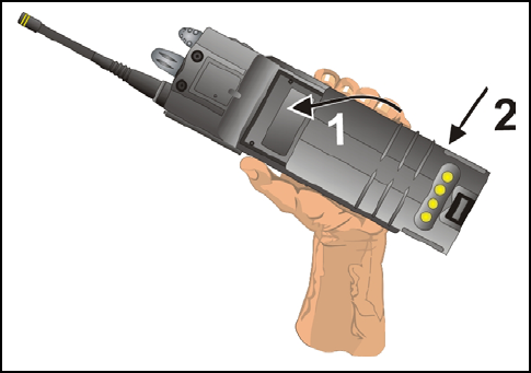
ATTACHING THE BATTERY PACK
Make sure the power to the radio is turned OFF.
1. Align the tab on the top of the battery pack with the
slot at the top of the battery cavity.
2. Push the battery pack down to attach the battery to the
radio.
3. Verify that the battery pack is properly latched to the
radio.
Figure 9 – Attaching the Battery Pack

41
BATTERY WARRANTY
A. M/A-COM, Inc. (hereinafter "Seller") warrants to the original purchaser for use
(hereinafter "Buyer") that nickel-cadmium and nickel-metal hydride batteries
supplied by Seller shall be free from defects in material and workmanship, and
shall conform to its published specifications for a period of twelve (12) months
from the date of purchase.
B. For purposes of this warranty, batteries shall be deemed defective if (1) the
battery capacity is less than 80% rated capacity, or (2) the battery develops
leakage.
C. If any battery fails to meet the foregoing warranty, Seller shall correct the
failure by issuing a replacement battery upon receipt of the defective battery at
an Authorized Service Center (ASC) or M/A-COM factory (for OpenSky®
Equipment only).
D. Replacement batteries shall be warranted only for the remaining unexpired
warranty period of the original battery. This warranty becomes void if:
1. The battery has been subjected to any kind of misuse, detrimental
exposure, or has been involved in an accident.
2. The battery is used in equipment or service other than the radio
equipment for which it is specified.
E. The preceding paragraphs set forth the exclusive remedies for claims based
upon defects in or non-conformity of any battery, whether the claim is in
contract, warranty, tort (including negligence), strict liability or otherwise, and
however instituted. Upon the expiration of the warranty period, all such liability
shall terminate. The foregoing warranties are exclusive and in lieu of all other
warranties, whether oral, written, expressed, implied or statutory. NO IMPLIED
OR STATUTORY WARRANTIES OF MERCHANTABILITY OR FITNESS FOR
PARTICULAR PURPOSE SHALL APPLY. IN NO EVENT SHALL THE
COMPANY BE LIABLE FOR ANY INCIDENTAL, CONSEQUENTIAL,
SPECIAL, INDIRECT OR EXEMPLARY DAMAGES.
This warranty applies only within the United States.
M/A-COM, Inc. M/A-COM, Inc.
1011 Pawtucket Blvd. 221 Jefferson Ridge Parkway
Lowell, MA 01853 Lynchburg, VA 24501
1-877-OPENSKY 1-800-528-7711
ECR-7048B

42
WARRANTY
A. M/A-COM, Inc. (hereinafter "Seller") warrants to the original purchaser
for use (hereinafter "Buyer") that Equipment manufactured by or for the
Seller shall be free from defects in material and workmanship, and
shall conform to its published specifications. With respect to all non-
M/A-COM Equipment, Seller gives no warranty, and only the warranty,
if any, given by the manufacturer shall apply. Rechargeable batteries
are excluded from this warranty but are warranted under a separate
Rechargeable Battery Warranty (ECR-7048).
B. Seller’s obligations set forth in Paragraph C below shall apply only to
failures to meet the above warranties occurring within the following
periods of time from date of sale to the Buyer and are conditioned on
Buyer’s giving written notice to Seller within thirty (30) days of such
occurrence:
1. for fuses and non-rechargeable batteries, operable on arrival
only.
2. for parts and accessories (except as noted in B.1) sold by
Seller’s Service Parts Operation, ninety (90) days.
3. for PANTHER Series handportable and mobile radios, two (2)
years.
4. for Cougar Series handportable and mobile radios, two (2)
years.
5. for OpenSky®, ProVoice™, and EDACS® Equipment of Seller’s
manufacture, one (1) year.
C. If any Equipment fails to meet the foregoing warranties, Seller shall
correct the failure at its option (i) by repairing any defective or
damaged part or parts thereof, (ii) by making available at Seller’s
factory any necessary repaired or replacement parts, or (iii) by
replacing the failed Equipment with equivalent new or refurbished
Equipment. Any repaired or replacement part furnished hereunder shall
be warranted for the remainder of the warranty period of the Equipment
in which it is installed. Where such failure cannot be corrected by
Seller’s reasonable efforts, the parties will negotiate an equitable
adjustment in price. Labor to perform warranty service will be provided
at no charge during the warranty period only for the Equipment
covered under Paragraph B.3-B.5. To be eligible for no-charge labor,

43
service must be performed at a M/A-COM factory (for OpenSky®
Equipment only), by an Authorized Service Center (ASC) or other
Servicer approved for these purposes either at its place of business
during normal business hours, for mobile or personal equipment, or at
the Buyer’s location, for fixed location equipment. Service on fixed
location equipment more than thirty (30) miles from the Service Center
or other approved Servicer’s place of business will include a charge for
transportation.
D. Seller’s obligations under Paragraph C shall not apply to any
Equipment, or part thereof, which (i) has been modified or otherwise
altered other than pursuant to Seller’s written instructions or written
approval or, (ii) is normally consumed in operation or, (iii) has a normal
life inherently shorter than the warranty periods specified in Paragraph
B, or (iv) is not properly stored, installed, used, maintained or repaired,
or, (v) has been subjected to any other kind of misuse or detrimental
exposure, or has been involved in an accident.
E. The preceding paragraphs set forth the exclusive remedies for claims
based upon defects in or nonconformity of the Equipment, whether the
claim is in contract, warranty, tort (including negligence), strict liability
or otherwise, and however instituted. Upon the expiration of the
warranty period, all such liability shall terminate. The foregoing
warranties are exclusive and in lieu of all other warranties, whether
oral, written, expressed, implied or statutory. NO IMPLIED OR
STATUTORY WARRANTIES OF MERCHANTABILITY OR FITNESS
FOR PARTICULAR PURPOSE SHALL APPLY. IN NO EVENT SHALL
THE SELLER BE LIABLE FOR ANY INCIDENTAL,
CONSEQUENTIAL, SPECIAL, INDIRECT OR EXEMPLARY
DAMAGES.
This warranty applies only within the United States.
M/A-COM, Inc. M/A-COM, Inc.
1011 Pawtucket Blvd. 221 Jefferson Ridge Parkway
Lowell, MA 01853 Lynchburg, VA 24501
1-877-OPENSKY 1-800-528-7711
ECR-7047B

M/A-COM, Inc.
221 Jefferson Ridge Parkway
Lynchburg, Virginia 24501
(Outside USA, 434-385-2400) Toll Free 800-528-7711
www.macom-wireless.com Printed in U.S.A.