HARRIS TR-0020-E M7100 UHF-L Mobile Radio User Manual MM102343V1 Ap1

HARRIS CORPORATION M7100 UHF-L Mobile Radio MM102343V1 Ap1

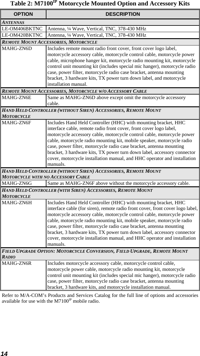
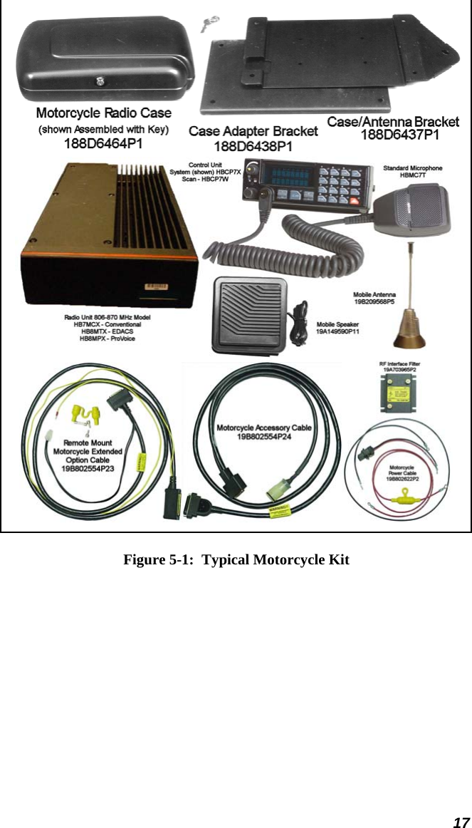
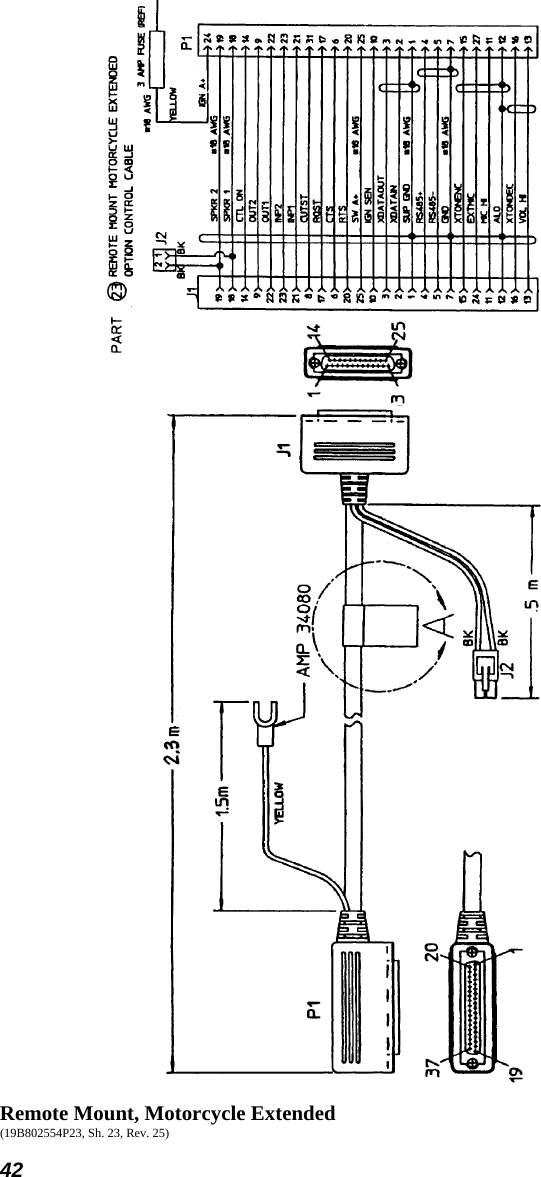
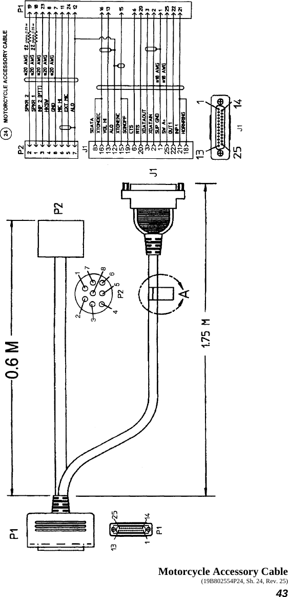
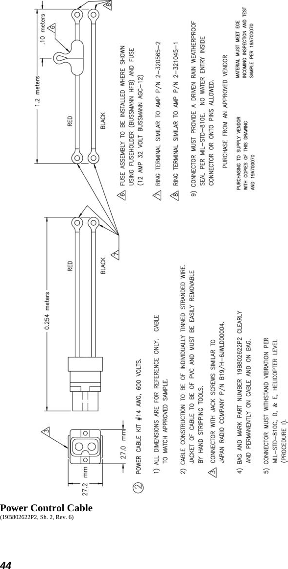
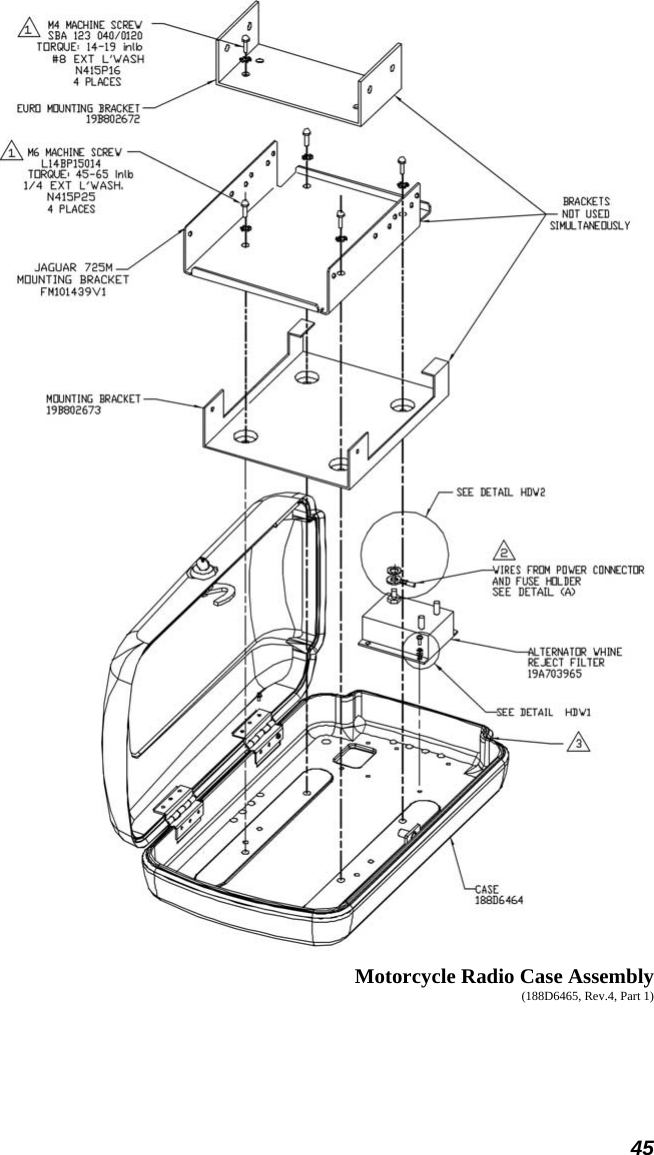
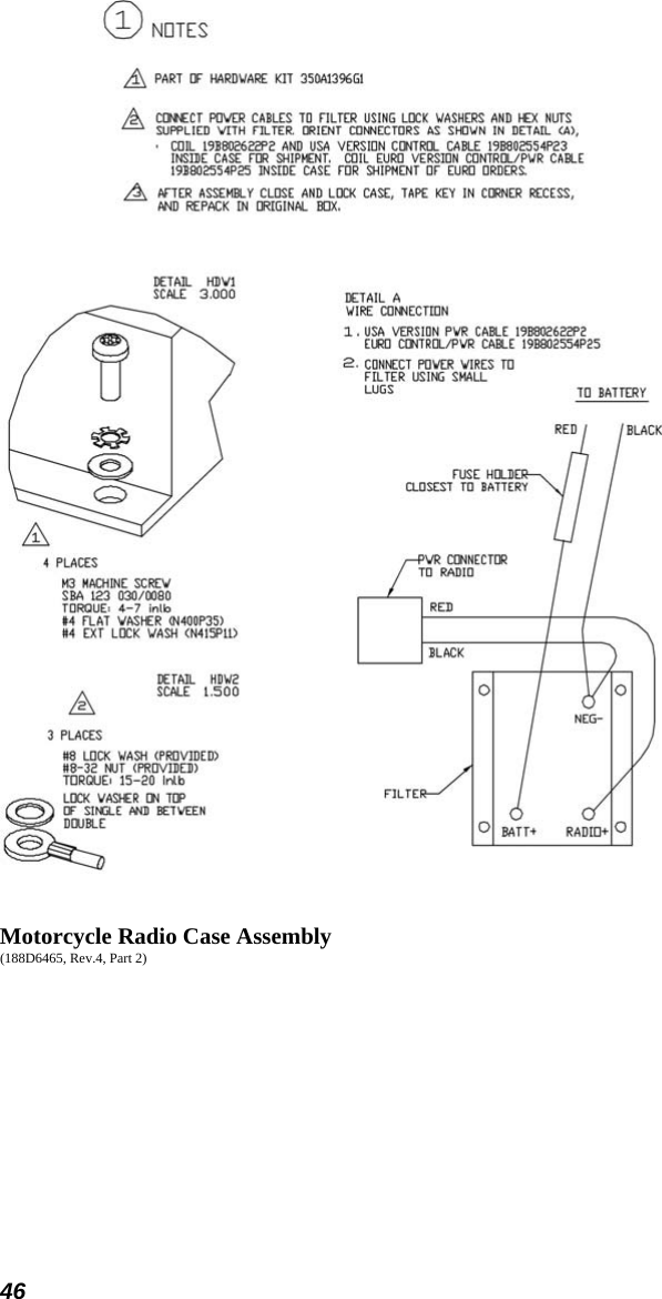
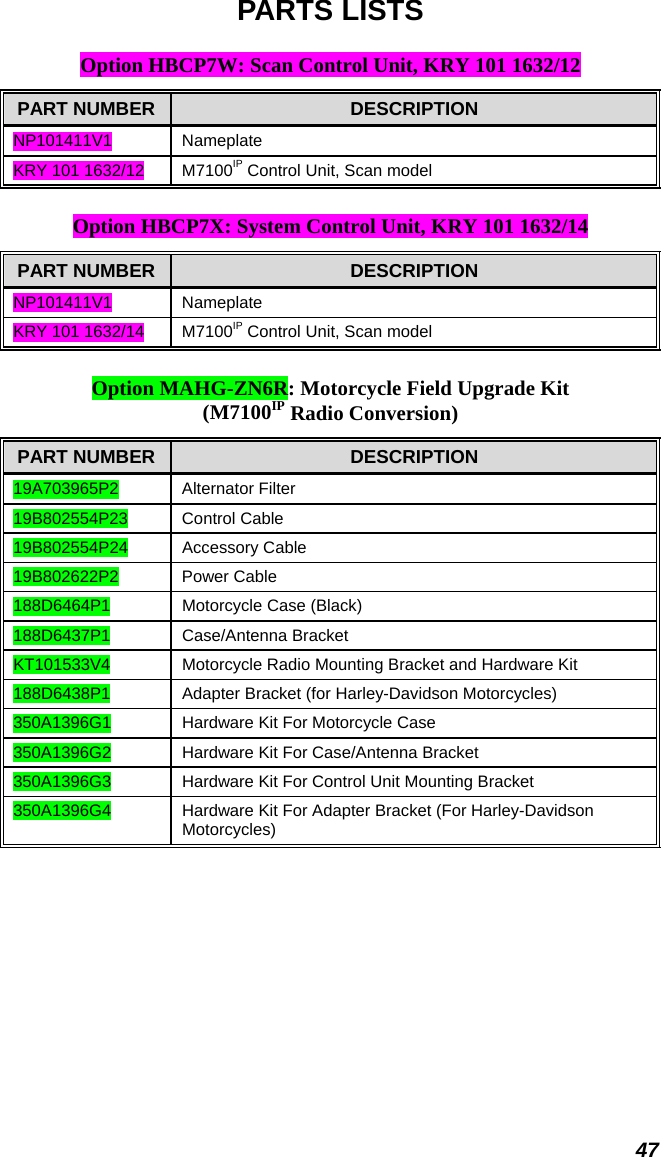
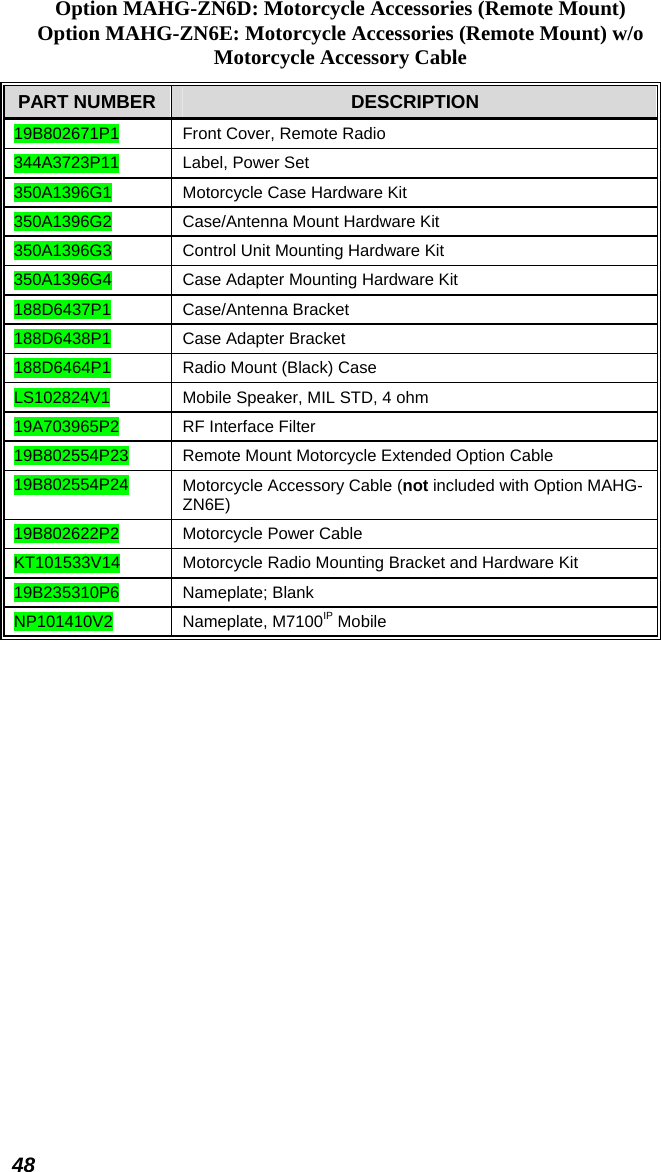
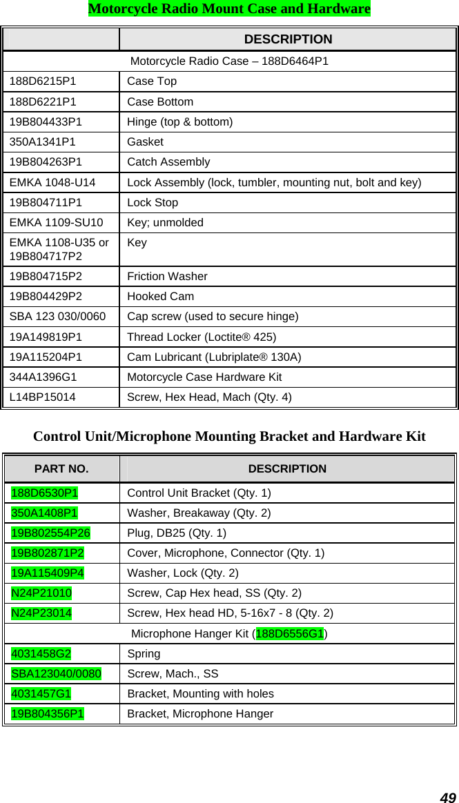
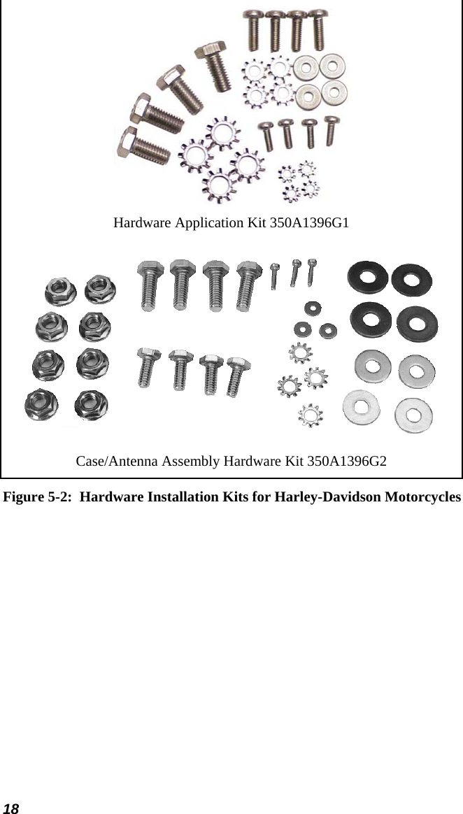
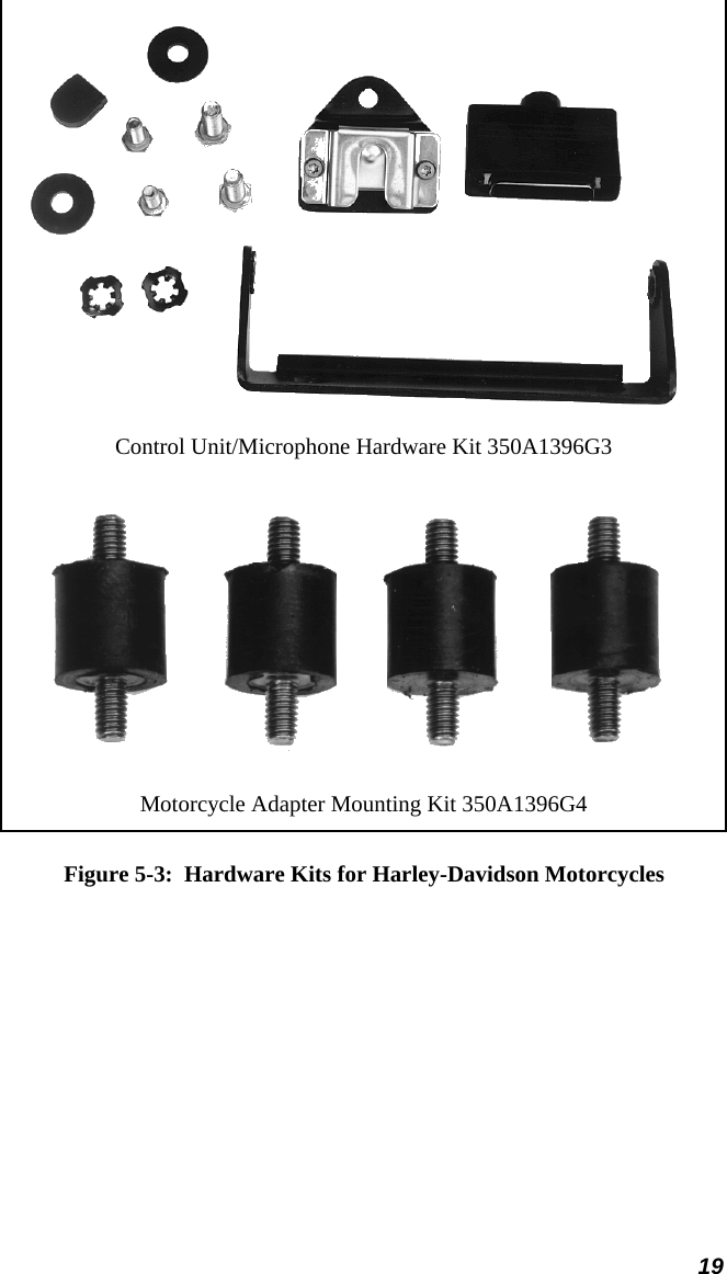
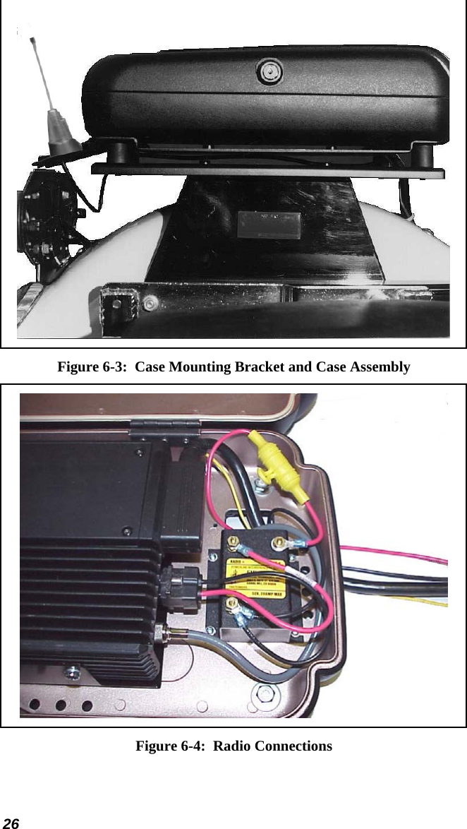
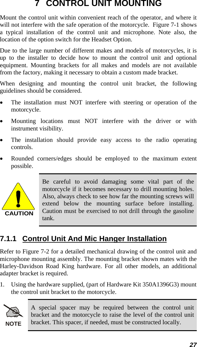
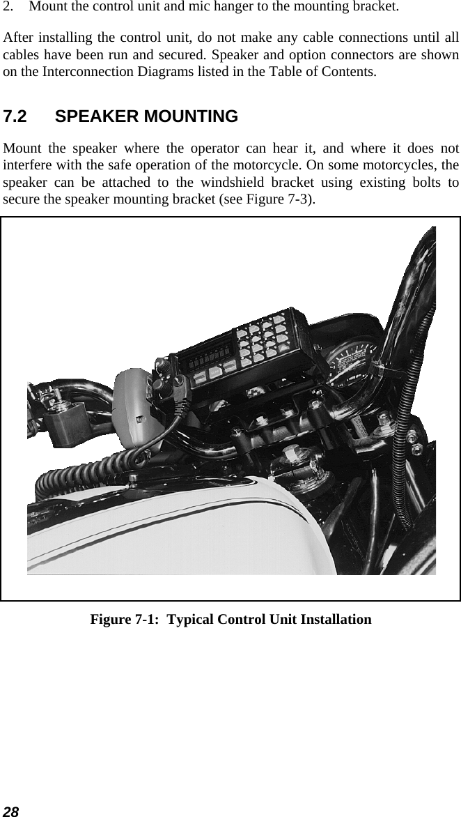
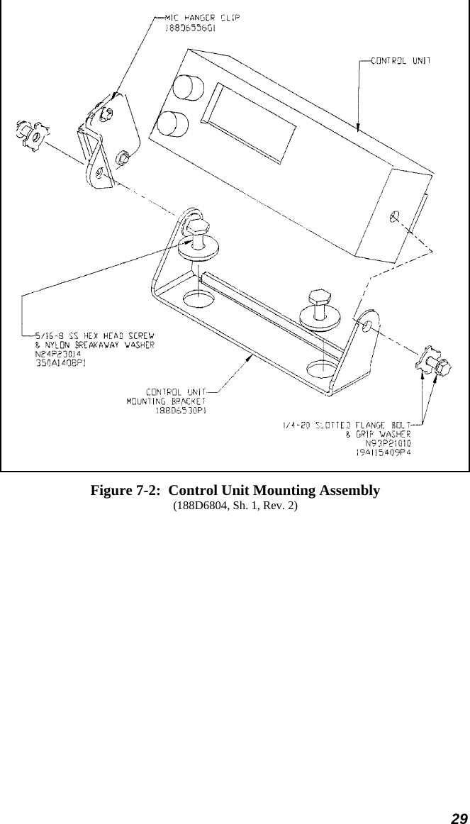
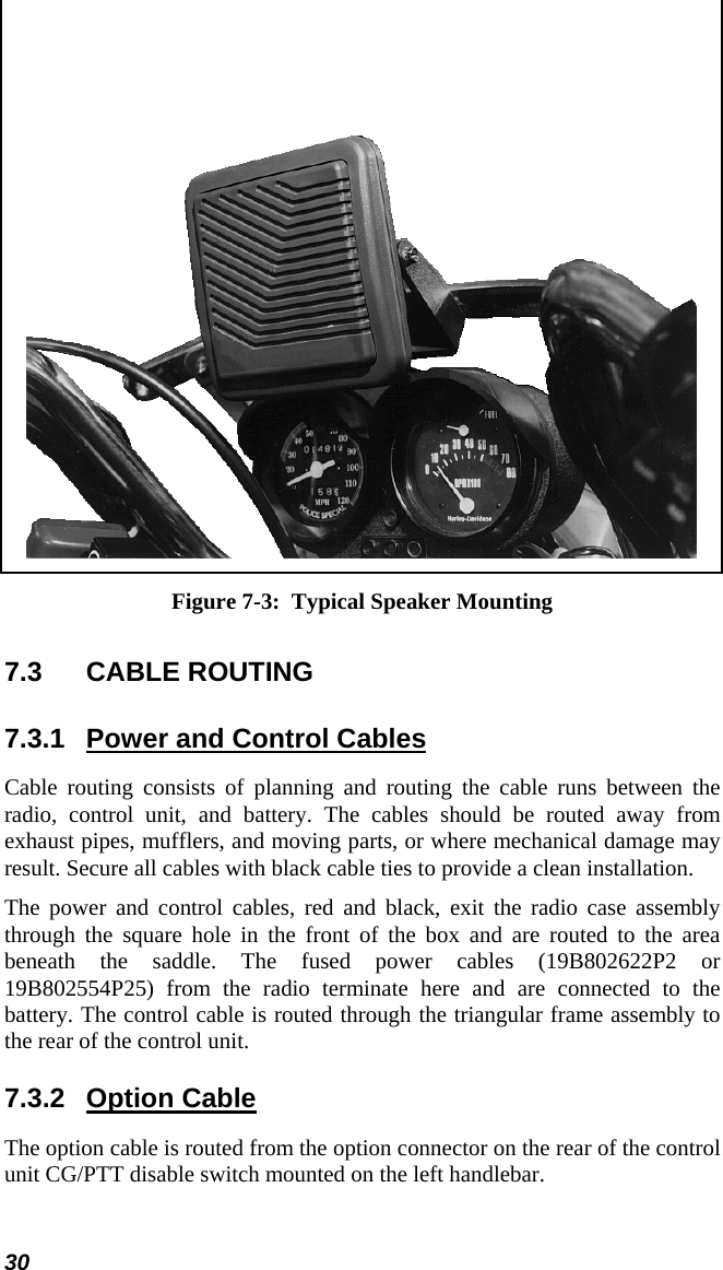
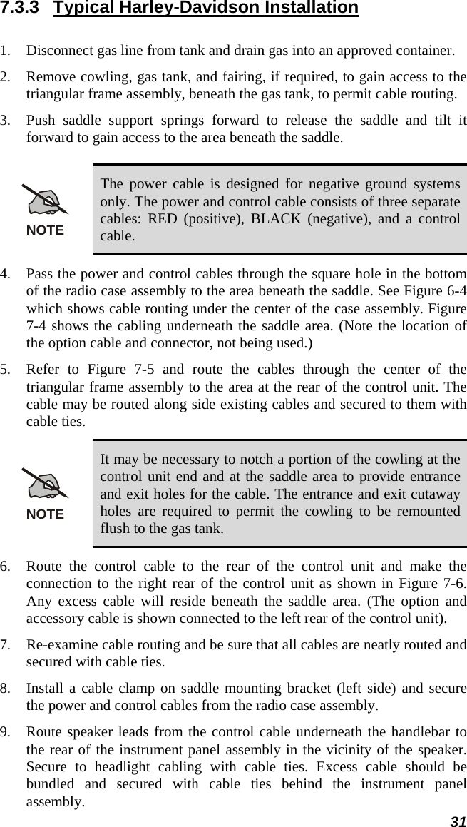
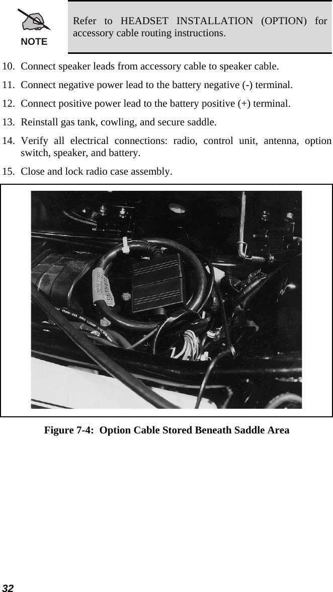
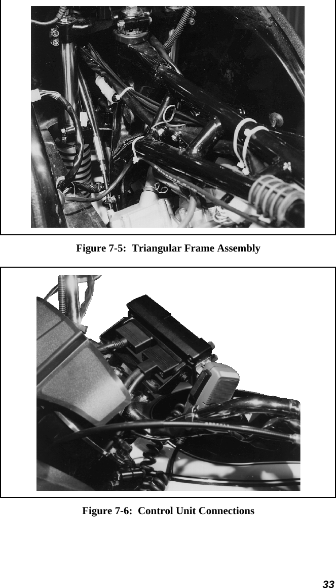
Manual motorcycle installation

 Installation Manual MM102343V1 Rev. Ap1, Mar-04  M7100IP Mobile Radio & Control Unit Motorcycle Installation
2 Copyright© 2004 M/A-COM, Inc. All rights reserved.REVISION HISTORY REV  DATE  SUMMARY OF CHANGES A  Mar. 2004  Initial release CREDITS EDACS is a registered trademark and PANTHER, M-PA, M-PD, MTL, TPX, PCS, M-RK, LPE-200, and Prism are trademarks of M/A-COM, Inc. All other brand and product names are trademarks, registered trademarks, or service marks of their respective holders. NOTICE The voice coding technology embodied in this product is protected by intellectual property rights including patent rights, copyrights, and trade secrets of Digital Voice Systems, Inc. The user of this technology is explicitly prohibited from attempting to decompile, reverse engineer, or disassemble the Object Code, or in any way convert the Object Code into human-readable form. NOTICE Repairs to this equipment should be made only by an authorized service technician or at a facility designated by the supplier. Any repairs, alterations or substitutions of recommended parts made by the user to this equipment not approved by the manufacturer could void the user’s authority to operate the equipment in addition to the manufacturers warranty. The software contained in this device is copyrighted by M/A-COM, Inc. Unpublished rights are reserved under the copyright laws of the United States. This manual is published by M/A-COM, Inc., without any warranty. Improvements and changes to this manual necessitated by typographical errors, inaccuracies of current information, or improvements to programs and/or equipment, may be made by M/A-COM, Inc., at any time and without notice. Such changes will be incorporated into new editions of this manual. No part of this manual may be reproduced or transmitted in any form or by any means,. electronic or mechanical, including photocopying and recording, for any purpose, without the express written permission of M/A-COM, Inc.
 3 TABLE OF CONTENTS  Page 1 SAFETY SYMBOL CONVENTIONS ................................................... 4 2 RF ENERGY EXPOSURE INFORMATION ....................................... 5 2.1 RF ENERGY EXPOSURE INFORMATION....................................... 5 2.1.1 Federal Communications Commission Regulations ................ 6 2.2 COMPLIANCE WITH RF EXPOSURE STANDARDS...................... 6 2.2.1 Mobile Antennas...................................................................... 7 2.2.2 Approved Accessories ............................................................. 7 2.2.3 Contact Information................................................................. 8 3 OPERATION SAFETY RECOMMENDATIONS................................ 9 3.1 TRANSMITTER HAZARDS ............................................................... 9 3.2 SAFE DRIVING RECOMMENDATIONS ........................................ 10 4 GENERAL INFORMATION ............................................................... 12 4.1 RELATED DOCUMENTATION....................................................... 12 5 OPTIONS AND ACCESSORIES ......................................................... 13 5.1 VENDOR DROP SHIP OPTIONS ..................................................... 15 5.1.1 External Headset Options...................................................... 15 5.2 HARDWARE KITS............................................................................ 16 5.3 USER SUPPLIED EQUIPMENT ....................................................... 20 5.4 POWER CONSIDERATIONS............................................................ 20 5.4.1 RF Power Adjustments.......................................................... 20 6 INSTALLATION................................................................................... 22 6.1 TOOLS REQUIRED........................................................................... 22 6.2 EQUIPMENT INSTALLATION........................................................ 22 6.2.1 Weather Resistant Case Assembly and Installation............... 22 6.2.2 Harley-Davidson Installation................................................. 25 6.3 RADIO MOUNTING BRACKETS.................................................... 25 7 CONTROL UNIT MOUNTING........................................................... 27 7.1.1 Control Unit And Mic Hanger Installation ............................ 27 7.2 SPEAKER MOUNTING..................................................................... 28 7.3 CABLE ROUTING............................................................................. 30 7.3.1 Power and Control Cables ..................................................... 30 7.3.2 Option Cable.......................................................................... 30 7.3.3 Typical Harley-Davidson Installation.................................... 31 7.4 CABLE CONNECTIONS................................................................... 34 7.4.1 Power Cable........................................................................... 35 7.4.2 Control Cable......................................................................... 35 7.4.3 Ignition Switch Option .......................................................... 35 7.4.4 Accessory Cable .................................................................... 36 7.5 ANTENNA INSTALLATION............................................................ 36 7.5.1 General .................................................................................. 36 7.5.2 Typical Motorcycle Mount Antenna Installation................... 37 8 FINAL CHECKS AND CONNECTIONS............................................ 38 8.1 HEADSET INSTALLATION (OPTION)........................................... 38 8.1.1 Dual Radio Application......................................................... 38 8.1.2 Headset Operation ................................................................. 39
4 1  SAFETY SYMBOL CONVENTIONS The following conventions are used throughout this manual to alert the user to general safety precautions that must be observed during all phases of operation, service, and repair of this product.  Failure to comply with these precautions or with specific warnings elsewhere in this manual violates safety standards of design, manufacture, and intended use of the product.  M/A-COM, Inc. assumes no liability for the customer’s failure to comply with these standards.  WARNING The  WARNING symbol calls attention to a procedure, practice, or the like, which, if not correctly performed or adhered to, could result in personal injury.  Do not proceed beyond a WARNING symbol until the conditions identified are fully understood or met.  CAUTION The  CAUTION symbol calls attention to an operating procedure, practice, or the like, which, if not performed correctly or adhered to, could result in damage to the equipment or severely degrade the equipment performance.  NOTE The  NOTE symbol calls attention to supplemental information, which may improve system performance or clarify a process or procedure.   The  ESD symbol calls attention to procedures, practices, or the like, which could expose equipment to the effects of Electro-Static Discharge. Proper precautions must be taken to prevent ESD when handling circuit modules.
 5 2  RF ENERGY EXPOSURE INFORMATION 2.1  RF ENERGY EXPOSURE AWARENESS, CONTROL INFORMATION, AND OPERATION INSTRUCTIONS FOR FCC OCCUPATIONAL USE REQUIREMENTS  BEFORE USING YOUR MOBILE TWO-WAY RADIO, READ THIS IMPORTANT RF ENERGY AWARENESS AND CONTROL INFORMATION AND OPERATIONAL INSTRUCTIONS TO ENSURE COMPLIANCE WITH THE FCC’S RF EXPOSURE GUIDELINES. NOTICE:  This radio is intended for use in occupational/controlled conditions, where users have full knowledge of their exposure and can exercise control over their exposure to meet FCC limits.  This radio device is NOT authorized for general population, consumer, or any other use. This two-way radio uses electromagnetic energy in the radio frequency (RF) spectrum to provide communications between two or more users over a distance.  It uses RF energy or radio waves to send and receive calls.  RF energy is one form of electromagnetic energy.  Other forms include, but are not limited to, electric power, sunlight, and x-rays.  RF energy, however, should not be confused with these other forms of electromagnetic energy, which, when used improperly, can cause biological damage.  Very high levels of x-rays, for example, can damage tissues and genetic material. Experts in science, engineering, medicine, health, and industry work with organizations to develop standards for exposure to RF energy.  These standards provide recommended levels of RF exposure for both workers and the general public.  These recommended RF exposure levels include substantial margins of protection.  All two-way radios marketed in North America are designed, manufactured, and tested to ensure they meet government established RF exposure levels.  In addition, manufacturers also recommend specific operating instructions to users of two-way radios.  These instructions are important because they inform users about RF energy exposure and provide simple procedures on how to control it.  Please refer to the following websites for more information on what RF energy exposure is and how to control your exposure to assure compliance with established RF exposure limits. http://www.fcc.gov/oet/rfsafety/rf-faqs.html http://www.osha.gov./SLTC/radiofrequencyradiation/index.html
6 2.1.1  Federal Communications Commission Regulations Your M/A-COM, Inc. M7100IP mobile two-way radio is designed and tested to comply with the FCC RF energy exposure limits for mobile two-way radios before it can be marketed in the United States.  When two-way radios are used as a consequence of employment, the FCC requires users to be fully aware of and able to control their exposure to meet occupational requirements.  Exposure awareness can be facilitated by the use of a label directing users to specific user awareness information.  Your M/A-COM, Inc. M7100IP two-way radio has an RF exposure product label.  Also, your M7100IP Installation and Operator’s Manuals include information and operating instructions required to control your RF exposure and to satisfy compliance requirements. 2.2  COMPLIANCE WITH RF EXPOSURE STANDARDS Your M/A-COM, Inc. M7100IP mobile two-way radio is designed and tested to comply with a number of national and international standards and guidelines (listed below) regarding human exposure to RF electromagnetic energy.  This radio complies with the IEEE and ICNIRP exposure limits for occupational/controlled RF exposure environment at duty factors of up to 50% talk-50% listen and is authorized by the FCC for occupational use.  In terms of measuring RF energy for compliance with the FCC exposure guidelines, your radio antenna radiates measurable RF energy only while it is transmitting (talking), not when it is receiving (listening) or in standby mode. Your M/A-COM, Inc. M7100IP mobile two-way radio complies with the following RF energy exposure standards and guidelines: •  United States Federal Communications Commission (FCC), Code of Federal Regulations; 47 CFR §§ 2 sub-part J. •  American National Standards Institute (ANSI)/Institute of Electrical and Electronic Engineers (IEEE) C95.1-1992. •  Institute of Electrical and Electronic Engineers (IEEE) C95.1-1999. NOTE – Table 1 lists the recommended minimum lateral distance for bystanders in an uncontrolled and controlled environment, from transmitting types of antennas (i.e., monopoles over a ground plane, or dipoles) at rated radio power for mobile radios installed on a motorcycle.
 7 Table 1: Rated Power and Recommended Minimum Lateral Distance RECOMMENDED MINIMUM LATERAL DISTANCE FROM TRANSMITTING ANTENNA MOBILE RADIO FREQUENCY SPLIT RATED POWER OF MOTORCYCLE-INSTALLED MOBILE TWO-WAY RADIO Controlled  Uncontrolled UHF–L @378 MHz  50 Watts (Antenna P/N: LE-OM406BKTNC) 74.87 cm  167.4 cm UHF–L @420 MHz  50 Watts (Antenna P/N: LE-OM420BKTNC) 71.03 cm  158.8 cm 2.2.1 Mobile Antennas Install the radio’s antenna (part number LE-OM406BKTNC for UHF-L  (378MHz) radios or LE-OM420BKTNC for UHF-L (420 MHz)) on the end of the motorcycle case farthest away from the driver.  These mobile antenna installation guidelines are limited to motorcycles fit with the motorcycle radio case with integral antenna grounding plane.  The antenna installation should additionally be in accordance with the following. 1.  The requirements of the antenna manufacturer/supplier included with the antenna. 2.  Instructions in the M7100IP Radio and Control Unit Motorcycle Installation Manual, including minimum antenna cable lengths. 3.  The installation manual providing specific information of how to install the antennas to facilitate recommended operating distances to all potentially exposed persons. Use only the M/A-COM approved/supplied antenna(s) or approved replacement antenna.  Unauthorized antennas, modifications, or attachments could damage the radio and may violate FCC regulations. 2.2.2 Approved Accessories This radio has been tested and meets the FCC RF exposure guidelines when used with the M/A-COM accessories supplied or designated for use with this product.  Use of other accessories may not ensure compliance with the FCC’s RF exposure guidelines, and may violate FCC regulations. For a list of M/A-COM approved accessories refer to the product manuals, M/A-COM’s Products and Services Catalog, or contact M/A-COM at 1-800-
8 528-7711. 2.2.3 Contact Information For additional information on exposure requirements or other information, contact M/A-COM, Inc. at 1-800-528-7711 or at http://www.macom-wireless.com.
 9 3  OPERATION SAFETY RECOMMENDATIONS 3.1 TRANSMITTER HAZARDS WARNING The operator of any mobile radio should be aware of certain hazards common to the operation of radio transmitters.  A list of several possible hazards is given: •  Explosive Atmospheres – Just as it is dangerous to fuel a vehicle with the motor running, similar hazards exist when operating a mobile radio.  Be sure to turn the radio off while fueling the motorcycle.  Do not transport containers of fuel.  Areas with potentially explosive atmosphere are often, but not always, clearly marked.  Turn OFF your radio when in any area with a potentially explosive atmosphere.  It is rare, but not impossible that the radio or its accessories could generate sparks. •  Interference to Vehicular Electronics Systems – Electronic fuel injection systems, electronic anti-skid braking systems, electronic cruise control systems, etc., are typical electronic systems that may malfunction due to the lack of protection from radio frequency energy present when transmitting.  If the vehicle contains such equipment, consult the dealer and enlist their aid in determining the expected performance of electronic circuits when the radio is transmitting. •  Electric Blasting Caps – To prevent accidental detonation of electric blasting caps, DO NOT use two-way radios within 1000 feet of blasting operations.  Always obey the “Turn Off Two-Way Radios” signs posted where electric blasting caps are being used. (OSHA Standard: 1926-900) •  Liquefied Petroleum (LP) Gas Powered Vehicles – Mobile radio installations in vehicles powered by liquefied petroleum gas with the LP gas container in the trunk or other sealed-off space within the interior of the vehicle must conform to the National  Fire  Protection  Association standard NFPA 58 requiring:   The space containing the radio equipment shall be isolated by a seal from the space containing the LP gas container and its fittings.   Outside filling connections shall be used for the LP gas container.   The LP gas container shall be vented to the outside of the vehicle.
10 3.2  SAFE DRIVING RECOMMENDATIONS (Recommended by AAA) •  Read the literature on the safe operation of the radio. •  Use both hands to steer and keep the microphone in its hanger whenever the vehicle is in motion. •  Place calls only when the vehicle is stopped. •  When talking from a moving vehicle is unavoidable, drive in the slower lane.  Keep conversations brief. •  If a conversation requires taking notes or complex thought, stop the vehicle in a safe place and continue the call. •  Whenever using a mobile radio, exercise caution.
 11      Figure 3-1:  Typical M7100IP Motorcycle Installation
12 4 GENERAL INFORMATION This manual contains instructions for installing the M7100IP mobile radio, M7100IP control unit, and associated hardware on a motorcycle.  The instructions in this manual are typical installation instructions, and are not intended to cover all makes and models of motorcycles. Final installation of the radio equipment is left to the discretion of the radio installer. To simplify installation and minimize difficulties, it is suggested that the installer read the entire manual prior to installation.  Figure 3-1 shows a typical motorcycle installation.  NOTE M/A-COM, Inc. does not assume liability for possible degradation of the radio or motorcycle performance due to mounting procedures. 4.1 RELATED DOCUMENTATION M7100IP Mobile Radio Operator’s Manual, Scan & System................................................................. MM102341V1 M7100IP Mobile Radio Installation Manual, Scan & System................................................................. MM102342V1 M7100IP Mobile Radio Motorcycle Installation Manual, (50W TX and Below) ...................................................... MM102343V1 M7100IP Mobile Radio Maintenance Manual UHF (378-430 MHz and 450-512 MHz).........................MM102346V1 VHF (136-174 MHz).......................................................MM102345V1 800 MHz (806-870 MHz)................................................MM102345V1
 13 5  OPTIONS AND ACCESSORIES Available options and accessories applicable to motorcycle installations are defined below. NOTE: The M7100IP mobile radio, control unit, accessory kits and microphone are ordered separately, then modified for motorcycle applications. Applicable hardware is included with each option.
14 Table 2: M7100IP Motorcycle Mounted Option and Accessory Kits OPTION  DESCRIPTION ANTENNAS LE-OM406BKTNC  Antenna, ¼ Wave, Vertical, TNC, 378-430 MHz LE-OM420BKTNC  Antenna, ¼ Wave, Vertical, TNC, 378-430 MHz REMOTE MOUNT ACCESSORIES, MOTORCYCLE MAHG-ZN6D  Includes remote mount radio front cover, front cover logo label, motorcycle accessory cable, motorcycle control cable, motorcycle power cable, microphone hanger kit, motorcycle radio mounting kit, motorcycle control unit mounting kit (includes special mic hanger), motorcycle radio case, power filter, motorcycle radio case bracket, antenna mounting bracket, 3 hardware kits, TX power turn down label, and motorcycle installation manual. REMOTE MOUNT ACCESSORIES, MOTORCYCLE W/O ACCESSORY CABLE MAHG-ZN6E  Same as MAHG-ZN6D above except omit the motorcycle accessory cable. HAND HELD CONTROLLER (WITHOUT SIREN) ACCESSORIES, REMOTE MOUNT MOTORCYCLE MAHG-ZN6F  Includes Hand Held Controller (HHC) with mounting bracket, HHC interface cable, remote radio front cover, front cover logo label, motorcycle accessory cable, motorcycle control cable, motorcycle power cable, motorcycle radio mounting kit, mobile speaker, motorcycle radio case, power filter, motorcycle radio case bracket, antenna mounting bracket, 3 hardware kits, TX power turn down label, accessory connector cover, motorcycle installation manual, and HHC operator and installation manuals. HAND HELD CONTROLLER (WITHOUT SIREN) ACCESSORIES, REMOTE MOUNT MOTORCYCLE WITH NO ACCESSORY CABLE MAHG-ZN6G  Same as MAHG-ZN6F above without the motorcycle accessory cable. HAND HELD CONTROLLER (WITH SIREN) ACCESSORIES, REMOTE MOUNT MOTORCYCLE MAHG-ZN6H  Includes Hand Held Controller (HHC) with mounting bracket, HHC interface cable (for siren), remote radio front cover, front cover logo label, motorcycle accessory cable, motorcycle control cable, motorcycle power cable, motorcycle radio mounting kit, mobile speaker, motorcycle radio case, power filter, motorcycle radio case bracket, antenna mounting bracket, 3 hardware kits, TX power turn down label, accessory connector cover, motorcycle installation manual, and HHC operator and installation manuals. FIELD UPGRADE OPTION: MOTORCYCLE CONVERSION, FIELD UPGRADE, REMOTE MOUNT RADIO MAHG-ZN6R  Includes motorcycle accessory cable, motorcycle control cable, motorcycle power cable, motorcycle radio mounting kit, motorcycle control unit mounting kit (includes special mic hanger), motorcycle radio case, power filter, motorcycle radio case bracket, antenna mounting bracket, 3 hardware kits, and motorcycle installation manual. Refer to M/A-COM’s Products and Services Catalog for the full line of options and accessories available for use with the M7100IP mobile radio.
 15 5.1  VENDOR DROP SHIP OPTIONS The following is a list of available Vendor drop-ship options. 5.1.1  External Headset Options There are two different applications for the Headset. One is for use with just the M7100IP mobile radio and the other is for use with the M7100IP mobile radio and a portable radio. KA-13  Helmet Kit: Bell BT400 with speaker and noise canceling microphone KA-23  Helmet Kit: Bell BT400 with dual speakers and noise canceling microphone (see NOTE on page 36) KA-13  Helmet Kit: SHOE1 TJ101 with speaker and noise canceling microphone KA-23  Helmet Kit: SHOE1 TJ101 with dual speakers and noise canceling microphone (see NOTE on page 36) MCH-71GT  Helmet Kit Interface Cable (pushbutton switch with PTT function; interfaces with KA-13 and KA-23 helmet kits; Harley-Davidson) MCH-72GT  Helmet Kit Interface Cable (rocker switch with PTT and CG decode disable functions; interfaces with KA-13 and KA-23 helmet kits; Harley-Davidson) 25-694  Extender Cable Assembly Interface. The following Belt Box Assembly Interfaces are for use with the dual application that allows the headset to be used with the M7100IP mobile radio and a portable radio: CA-3G3:  Dual Radio Belt Box for PANTHER™ 400P, 600P, 625P. CA-3G5:  Dual Radio Belt Box for JAGUAR 700P. CA-3GK:   Dual Radio Belt Box for M-PA™, M-PD™, MTL™, TPX™. CA-3GP:   Dual Radio Belt Box for PCS™. CA-3GV:   Dual Radio Belt Box for M-RK™. CA-3GY:  Dual Radio Belt Box for LPE-200™, Prism™.
16 5.2 HARDWARE KITS The typical motorcycle mount application requirements are shown in Figure 5-1 (radio, control unit, microphone, and antenna are all ordered separately). Hardware Kits 350A1396G1-G4 are shown in Figure 5-2 and Figure 5-3.  Hardware kit 350A1396G1 is used to factory-install the radio mounting bracket and alternator whine reject filter to the weather-resistant case.  Hardware kits, 350A1396G2-G4, are used by the customer in the field to mount the case and control head to the motorcycle (and may require the optional Harley-Davidson adapter bracket).  •  MIL-STD weather-resistant locking M7100IP radio case with integral antenna ground plane •  Motorcycle Case hardware kit •  Motorcycle Radio Mounting bracket and hardware •  Case/Antenna bracket •  Case/Antenna Mount hardware kit •  Control Unit Mount hardware kit •  Case Adapter bracket (for Harley-Davidson motorcycles) •  Case Adapter Mount hardware kit •  RF Interface filter •  MIL-STD weatherproof speaker •  Radio-to-Control Unit Motorcycle cable •  Motorcycle Accessory cable •  Power/Control cable
 17    Figure 5-1:  Typical Motorcycle Kit
18  Hardware Application Kit 350A1396G1  Case/Antenna Assembly Hardware Kit 350A1396G2 Figure 5-2:  Hardware Installation Kits for Harley-Davidson Motorcycles
 19  Control Unit/Microphone Hardware Kit 350A1396G3  Motorcycle Adapter Mounting Kit 350A1396G4 Figure 5-3:  Hardware Kits for Harley-Davidson Motorcycles
20 5.3  USER SUPPLIED EQUIPMENT •  Motorcycle Bracket (Motorcycle’s interface with this Motorcycle Radio Case and associated hardware.  Refer to  and  in Figure 6-1 and Figure 6-2.) 5.4 POWER CONSIDERATIONS The motorcycle may be equipped with additional lights, light flashers, sirens, PA systems, etc. Therefore, consideration must be given to the total system current drain. It is recommended that the radios be set to not exceed the applicable rated RF power output and current drain shown in Table 5-3 for all M7100IP motorcycle applications.  CAUTION Do NOT use a M7100IP mobile radio with power exceeding the power limits shown in Table 5-3 for motorcycle applications.  To do so will result in damage to the motorcycle alternator, battery, and all circuits.  Also, the possibility of interference is increased if the proper RF power level is not used. As a final note, RF power may not be set to exceed the maximum regulatory RF power specified by that country’s regulatory agency. 5.4.1  RF Power Adjustments For factory installed options the maximum RF power levels are factory preset and should only require verification in the field.  See Table 5-3. For field installed options, the RF power of previously purchased M7100IP mobile radios in the field must be appropriately set via modification of the maximum RF power tracking data fields. The tracking data numbers are adjusted to produce RF power as specified in the actual “M7100IP Motorcycle Radio RF Power” column in Table 5-3. 5.4.1.1  Setting RF Power in the Field 800 MHz Band: •  Adjust the RF Power Level Tracking Data 1.  Using ProGrammer, read the personality from the radio.  (Refer to ProGrammer On-Line Help for detailed instructions.) 2.  Click on the “Systems” tab, then double click on “System Setup.” 3.  Select the “General” tab and choose the System Name that needs to be adjusted.
 21 4.  Enter “20” (for 20 watts rated power) in the “Power Level” control box.  Click OK.  In addition, an RF Power of 10 or 15 watts can be set by entering “10” or “15” respectively, in the “Power Level” control field (refer to Table 5-3). 5.  Write the new personality to radio. The 800 MHz RF power tracking data settings are listed in the M7100IP Mobile Radio Maintenance Manual ?? under the sections for TRACKING DATA, TEST FREQUENCIES, & SETTING TRACKING DATA. Table 5-3:  RF Power Versus Current Setting STANDARD M7100IP MOBILE RADIO RF POWER M7100IP MOBILE RADIO RF POWER (MOTORCYCLE INSTALLATION) RF PWR (Rated) CURRENT (Typical) RF PWR (Rated) RF POWER SETTING (Typical) CURRENT (Typical) Repeater Input Band 806-825 MHz  806-825 MHz 35W 15A 20W 20W 9A N/A N/A 15W 14.7W 8A 10W 7A 10W 10.2W 7A Talkaround Band 851-870 MHz  851-870 MHz 30W 15A 20W 20W 8A N/A N/A 15W 14W 7A 10W 7A 10W 10W 6A
22 6 INSTALLATION Installation of the M7100IP mobile radio and control unit consists of: •  Assembling and installing the weather resistant motorcycle case assembly, including the adapter bracket, case/antenna mounting bracket, and bottom case (previously assembled) to the existing interfacing bracket on the motorcycle (user supplied). •  Installing the radio in the radio mounting bracket located inside the weather-resistant case. •  Installing the control unit, microphone, and speaker. •  Installing the antenna. •  Routing the power, control, and option cables. •  Connecting all cables, including power, control, and option cables. •  Installing the Headset Option. •  Performing an operational check All mounting hardware consists of stainless steel screws, locknuts, nuts, and lockwashers to resist corrosion. 6.1 TOOLS REQUIRED •  Socket wrench set U.S./metric with 3" extender •  Open end wrench, adjustable •  Wire clippers •  TORX® BIT set, small metric 6.2 EQUIPMENT INSTALLATION 6.2.1  Weather Resistant Case Assembly and Installation The motorcycle Weather Resistant Case Assembly may be installed on almost any motorcycle. Installation instructions provided here include information for the Harley-Davidson Dyna and Road King models. Figure 6-1 and Figure 6-2 illustrate installation on Harley-Davidson motorcycles.  Refer to these diagrams during installation.  Installation on other motorcycles is at the discretion of the installer.
 23  Figure 6-1:  Radio Installation (188D6803, Sh. 1A, Rev. 3)
24  Figure 6-2:  Radio Installation (188D6803, Sh. 1B, Rev. 3)
 25 6.2.2 Harley-Davidson Installation 1.  Unpack the weather resistant motorcycle case, remove the key taped to the top cover and open the case. 2.  Refer to Figure 6-1 and Figure 6-2 and verify all components shown in the diagrams are available. 3.  Mount the adapter bracket to the existing Dyna or Road King (interface) bracket on the motorcycle (user supplied) using the 1/4-20 x 5/8 screws provided.  NOTE The interface radio mounting bracket (user supplied) for the Dyna and Road King models are different and require a different mounting hole configuration. See Figure 6-1 and Figure 6-2.  4.  Insert the power, control, and antenna cables through the square hole in the case/antenna mounting bracket and then through the bottom case assembly. 5.  Mount the case mounting bracket and bottom case assembly onto the 4 resilient mounts using the serrated flange nuts and flat washers included inside the case. Refer to Figure 6-3. 6.  Refer to Figure 6-4and connect the power cable to the radio. (Refer to Cable Connections.) 7.  Position the radio, fins up, inside the bracket in the bottom case assembly and slide onto the arms. Lock in place using the TORX head screws and lock washers (taped to the radio bracket). 8.  Refer to Figure 6-4:  Radio Connections and connect the antenna and control cables to the radio. (Refer to Antenna Installation.) 9.  Mount the antenna to the case/antenna mounting bracket using the M3 x 16 mm pan head screws provided. Refer to Figure 6-3. 6.3  RADIO MOUNTING BRACKETS Radio mounting brackets are not available from M/A-COM for all models of bikes. Should a special application arise for a custom-made radio mounting bracket, it must be made using 0.125" steel (minimum). When designing and mounting the bracket, corners/edges should be rounded to the maximum extent possible.
26  Figure 6-3:  Case Mounting Bracket and Case Assembly  Figure 6-4:  Radio Connections
 27 7  CONTROL UNIT MOUNTING Mount the control unit within convenient reach of the operator, and where it will not interfere with the safe operation of the motorcycle.  Figure 7-1 shows a typical installation of the control unit and microphone. Note also, the location of the option switch for the Headset Option. Due to the large number of different makes and models of motorcycles, it is up to the installer to decide how to mount the control unit and optional equipment. Mounting brackets for all makes and models are not available from the factory, making it necessary to obtain a custom made bracket. When designing and mounting the control unit bracket, the following guidelines should be considered. •  The installation must NOT interfere with steering or operation of the motorcycle. •  Mounting locations must NOT interfere with the driver or with instrument visibility. •  The installation should provide easy access to the radio operating controls. •  Rounded corners/edges should be employed to the maximum extent possible. CAUTION Be careful to avoid damaging some vital part of the motorcycle if it becomes necessary to drill mounting holes. Also, always check to see how far the mounting screws will extend below the mounting surface before installing. Caution must be exercised to not drill through the gasoline tank. 7.1.1  Control Unit And Mic Hanger Installation Refer to Figure 7-2 for a detailed mechanical drawing of the control unit and microphone mounting assembly. The mounting bracket shown mates with the Harley-Davidson Road King hardware. For all other models, an additional adapter bracket is required. 1.   Using the hardware supplied, (part of Hardware Kit 350A1396G3) mount the control unit bracket to the motorcycle. NOTE A special spacer may be required between the control unit bracket and the motorcycle to raise the level of the control unit bracket. This spacer, if needed, must be constructed locally.
28 2.  Mount the control unit and mic hanger to the mounting bracket. After installing the control unit, do not make any cable connections until all cables have been run and secured. Speaker and option connectors are shown on the Interconnection Diagrams listed in the Table of Contents. 7.2 SPEAKER MOUNTING Mount the speaker where the operator can hear it, and where it does not interfere with the safe operation of the motorcycle. On some motorcycles, the speaker can be attached to the windshield bracket using existing bolts to secure the speaker mounting bracket (see Figure 7-3).  Figure 7-1:  Typical Control Unit Installation
 29  Figure 7-2:  Control Unit Mounting Assembly (188D6804, Sh. 1, Rev. 2)
30  Figure 7-3:  Typical Speaker Mounting 7.3  CABLE ROUTING  7.3.1  Power and Control Cables Cable routing consists of planning and routing the cable runs between the radio, control unit, and battery. The cables should be routed away from exhaust pipes, mufflers, and moving parts, or where mechanical damage may result. Secure all cables with black cable ties to provide a clean installation. The power and control cables, red and black, exit the radio case assembly through the square hole in the front of the box and are routed to the area beneath the saddle. The fused power cables (19B802622P2 or 19B802554P25) from the radio terminate here and are connected to the battery. The control cable is routed through the triangular frame assembly to the rear of the control unit. 7.3.2 Option Cable The option cable is routed from the option connector on the rear of the control unit CG/PTT disable switch mounted on the left handlebar.
 31 7.3.3  Typical Harley-Davidson Installation 1.  Disconnect gas line from tank and drain gas into an approved container. 2.  Remove cowling, gas tank, and fairing, if required, to gain access to the triangular frame assembly, beneath the gas tank, to permit cable routing. 3.  Push saddle support springs forward to release the saddle and tilt it forward to gain access to the area beneath the saddle. NOTE The power cable is designed for negative ground systems only. The power and control cable consists of three separate cables: RED (positive), BLACK (negative), and a control cable. 4.  Pass the power and control cables through the square hole in the bottom of the radio case assembly to the area beneath the saddle. See Figure 6-4 which shows cable routing under the center of the case assembly. Figure 7-4 shows the cabling underneath the saddle area. (Note the location of the option cable and connector, not being used.) 5.  Refer to Figure 7-5 and route the cables through the center of the triangular frame assembly to the area at the rear of the control unit. The cable may be routed along side existing cables and secured to them with cable ties. NOTE It may be necessary to notch a portion of the cowling at the control unit end and at the saddle area to provide entrance and exit holes for the cable. The entrance and exit cutaway holes are required to permit the cowling to be remounted flush to the gas tank. 6.  Route the control cable to the rear of the control unit and make the connection to the right rear of the control unit as shown in Figure 7-6.  Any excess cable will reside beneath the saddle area. (The option and accessory cable is shown connected to the left rear of the control unit). 7.  Re-examine cable routing and be sure that all cables are neatly routed and secured with cable ties. 8.  Install a cable clamp on saddle mounting bracket (left side) and secure the power and control cables from the radio case assembly. 9.  Route speaker leads from the control cable underneath the handlebar to the rear of the instrument panel assembly in the vicinity of the speaker. Secure to headlight cabling with cable ties. Excess cable should be bundled and secured with cable ties behind the instrument panel assembly.
32 NOTE Refer to HEADSET INSTALLATION (OPTION) for accessory cable routing instructions. 10.  Connect speaker leads from accessory cable to speaker cable. 11.  Connect negative power lead to the battery negative (-) terminal. 12.  Connect positive power lead to the battery positive (+) terminal. 13.  Reinstall gas tank, cowling, and secure saddle. 14. Verify all electrical connections: radio, control unit, antenna, option switch, speaker, and battery. 15.  Close and lock radio case assembly.  Figure 7-4:  Option Cable Stored Beneath Saddle Area
 33  Figure 7-5:  Triangular Frame Assembly  Figure 7-6:  Control Unit Connections
34 7.3.3.1  For Motorcycle Models Equipped with Gas Tank Fairing The cable may be routed from the saddle area, under the fairing, around the left side of the gas tank filler pipe, and up to the area of the control unit. The fairing may have to be notched to provide entrance and exit space. Run the control cable as directed in Steps 1 through 3. 1.  Remove all the screws securing the fairing. Next, unscrew and remove the gas tank cap and lift off the fairing. Replace the gas cap immediately. WARNING Always replace the gas cap as soon as the fairing is replaced/removed. This is necessary to reduce the possibility of an explosion as well as to prevent drill shavings or other debris from getting into the gas tank. 2.  Run the cables from the saddle area up the left side of the gas tank to the area of the control unit. NOTE It may be necessary to notch a portion of the fairing at the control unit end and at the saddle area to provide entrance and exit holes for the cable. The entrance and exit cutaway holes are required to permit the fairing to be remounted flush to the gas tank. 3.  Before replacing the fairing, the control cable and any option cables may be run under the fairing also. Replace the fairing by removing the gas cap, repositioning the fairing, then replacing the gas cap and the screws that secure the fairing. 7.3.3.2  For Motorcycles Not Equipped With A Gas Tank Fairing After making power connections, run the control cables up the left side of the motorcycle to the control unit and secure the cables with the cable ties. Note: All cables connect to the back of the control unit. 7.4 CABLE CONNECTIONS Cable connections consist of connecting the power and control cables (individual red + and black -), the radio control cable, and the antenna cable. Verify that all cables have been connected and are secure. Refer to control cable assembly drawings 19B802554 and Interconnection Drawings (188D6783) for electrical and mechanical application details.
 35 7.4.1 Power Cable As shipped from the factory, the power cable (19B802622P2) is equipped with a 12 amp in-line fuse (installed) and ring terminals. The power cable supplies power from the battery to the radio. Refer to Figure 6-4. 1.  Connect the red lead (+) to the battery terminal on the alternator whine filter and the black lead (-) to ground on the alternator whine filter. 2.  Route the cables to the battery and then connect the black (-) and the red lead (+) to the battery terminals. 7.4.2 Control Cable The control cable (remote mount, extended option) is routed between the control unit and the motorcycle radio case. In addition to the main cable, the cable assembly contains a pair of black speaker leads and a single yellow wire for ignition switch standby control. Normally, the ignition switch standby control feature is not used in motorcycle applications and the yellow fuse assembly provided is discarded and the wire terminated. However, at the customer’s discretion, the ignition switch standby control feature may be used. The plug connections include the microphone, speaker, option cable, and the control cable. Refer to the interconnection diagram 188D6783 and to diagram 19B802554P23 for cable identification. 1.  Plug the black speaker leads from the control cable into the speaker cable. 2.  Plug the control cable into the right rear receptacle of the control unit. 7.4.3  Ignition Switch Option NOTE The M7100IP radio, as shipped from the factory, has the “ignition sense” feature disabled. As such, the radio is powered ON or OFF as determined by the front panel ON-OFF/VOLUME control only (assuming A+ and A- are connected). If the “ignition sense” feature is to be enabled, open the top cover of the radio and remove the shield from the logic PWB. Slide switch SW601 from position 3-2 to 1-2. Replace shield and top cover. Be sure to apply the correct torque to the screws holding the top cover in place. Refer to the M7100IP Maintenance Manual for installation instructions.
36 7.4.4 Accessory Cable  The accessory cable (19B802554P24) provides connections for the external headset, DES keyloader, and other options (i.e., data terminal, external encoder/decoder, etc). Refer to “HEADSET INSTALLATION (OPTION).” 7.5 ANTENNA INSTALLATION 7.5.1 General The M/A-COM M7100IP motorcycle options for the UHF (378-430 MHz) land mobile radio band are designed for use with two antennas (part number LE-OM406BKTNC for 378-420 MHz or LE-OM420BKTNC for 420-430 MHz). With this antenna, a ground plane is no longer necessary. This antenna is an end-fed high-impedance antenna that provides the proper VSWR and radiation pattern without the use of a ground plane. Typical antenna gain without a ground plane is 0 dB.  The case/antenna mounting plate (188D6437P1) was designed to fit the hole mounting pattern for either of the two antenna mounts. CAUTION Since the two antennas are high impedance, voltage fed antennas, the length of the coaxial cable from the antennas to the M7100IP RF port is critical. It cannot be just any arbitrary length. To prevent possible extraneous radiation, RFI feedback from the antenna to the radio, high VSWR, or antenna ground currents, select an antenna coaxial cable length that is close to a multiple of an odd quarter-wavelength. To properly use a thru-line wattmeter, one of the following two conditions must be met: •  If the wattmeter is installed right at the M7100IP RF port and the odd multiple of a quarter-wavelength of coax to the antenna is used, correct readings will result. Any other length of coax will result in improper readings. •  If a length of coax equal to a multiple of a half-wave length is installed between the M7100IP RF port and the thru-line wattmeter and an odd multiple of a quarter-wavelength of coax to the antenna is used, correct readings will also result. Any other length of coax will result in improper readings. To calculate the proper cable length of the antenna coaxial cable, proceed as follows:
 37 1.  Determine the center frequency of the majority of programmed transmit channel frequencies. 2.  Use the formula:    ¼λ in =  2805          F(MHz) Example 1: Assume the customer has an 800 MHz M7100IP with most of the transmit frequencies between 816-821 MHz. Therefore, center frequency is 818.5 MHz. Applying the above formula results in:  ¼λ in =   2805  = 3.43 inches  818.5  ½λ wavelength (in inches)= 6.85 inches The cable length should be 3.43 + n x 6.85 inches. Since the installer will need a length of the coax from the antenna to the radio to be at least 22 inches long to physically connect the antenna to the radio, he must calculate a length of coax that will meet the odd quarter-wavelength requirement and be greater than 22 inches.  Choose n=3. Coaxial cable length is 3.43 + 3 x 6.85= 23.99 inches. Example 2: Assume the center frequency is 155 MHz. Applying the formula: ¼λ = 18.10 inches; ½ wavelength = 36.19 inches; n=1.  Coaxial cable length is 18.10 + 1 x 36.19= 54.29 inches. 7.5.2  Typical Motorcycle Mount Antenna Installation The typical motorcycle mounting of an antenna is only applicable when the installation provides at least 20 centimeters (8 inches) between the antenna and operators/bystanders. This distance recommendation is made using a 50% duty cycle. 1.  After the proper length of coax cable has been calculated, cut the coax cable so that when the TNC crimp style connector is installed the overall length will equal the calculated length. 2.  Route the assembled proper length coax from the antenna, under the antenna bracket, and into the weather-resistant case. 3.  Connect the antenna cable to the RF port on the M7100IP radio. WARNING See the “RF ENERGY EXPOSURE INFORMATION” section at the beginning of this manual for further information regarding Maximum Permissible Exposure (MPE) limits of RF radiation absorption set by the FCC.
38 8  FINAL CHECKS AND CONNECTIONS After the weather resistant case is installed, all cables run, and the radio, control unit, speaker, and microphone installed, refer to the interconnection diagrams and verify that all connections have been made and the equipment is properly grounded. Make a final check of all cables to make sure they are properly connected and dressed away from all moving parts and exhaust pipes, and secured with cable ties. Then recheck all electrical connections and radio mounting hardware. 8.1  HEADSET INSTALLATION (OPTION) NOTE To enable the PTT switch on the handlebar switch for external headset options, the M7100IP mobile radio must be programmed so that INP2 is defined to be “PTT” or “EXTPTT”. Without this software addition, the headset options will not transmit. 8.1.1  Dual Radio (i.e., M7100IP Mobile and Portable Radio) Application The Headset Option includes the helmet-mounted noise canceling microphone with single (or dual) speakers, the belt box assembly (with internal amplifier), and the Helmet Kit Interface Cable. 1.  Install the noise-canceling microphone and single (or dual) speakers in the helmet per instructions provided by the vendor. 2.  Remove the plug 19B802554P26 from the option connector on the back of the M7100IP radio control unit. Connect the accessory cable 19B802554P24 to the option connector. 3.  Install the Helmet Kit Interface Cable (MCH-71GT, etc.) containing the PTT only pushbutton switch or the PTT/CG disable switch to the left handlebar, insuring that freedom of motion is not compromised. Route the eight pin waterproof connector over to and mate it with the eight pin waterproof connector that is part of accessory cable 19B802554P24. 4.  Route the long end of the Helmet Kit Interface Cable containing the four position quick disconnect plug along the bike and bring it out near the location of the driver’s hip. 5.  The long end of the accessory cable 19B802554P24 which contains the 25 pin D-subminiature receptacle connector is to also be routed along the bike and any excess is to be coiled up and left under the seat. 6.  The driver takes the belt boxes (listed on page 10) and attaches it to his belt. The helmet kit quick disconnect plug is mated to the belt box quick disconnect connector.
 39 7.  Finally, the other quick disconnect connector of the belt box is mated to the Helmet Kit Interface Cable quick disconnect connector. Orion Mobile Radio Only Appllication This Headset Option includes the helmet-mounted noise canceling microphone with single (or dual) speakers, the extender cable assembly, and the Helmet Kit Interface Cable. 1.  Follow steps 1-5 of the “Dual Radio Application.” 2.  The helmet kit quick disconnect plug is mated to the extender cable 25-0694 (no need for a belt box). 3.  Finally, the other quick disconnect connector of the extender cable is mated to the Helmet Kit Interface Cable quick disconnect connector. NOTE The headset option speakers are a nominal 24 ohms.  Use of other impedance vale speakers will result in non-optimum sound performance from the speaker(s).  The KA-23 dual speaker helmet kit has the two speakers wired in parallel.  They must be re-wired in series to perform properly. NOTE The Helmet Kit Interface Cables MCH-71GT and MCK-71GT have a pushbutton switch that only supports the PTT function.  The Interface Cables MCH-72GT and MCK-72GT have a three-position rocker switch that supports both the PTT and CG Decode Disable functions. 8.1.2 Headset Operation 1.  If the motorcycle is equipped with the MCH-71GT or MCK-71GT Motorcycle Interface cable, simply press and hold the PTT button (and talk into the noise-canceling mic) to transmit.  Release the PTT button to receive.  Adjust the volume switch on the control head for the desired level. 2.  If the motorcycle is equipped with the MCH-72GT or MCK-72GT Motorcycle Interface cable, press and hold the three position toggle switch to the momentary (PTT) position (and talk into the noise-canceling mic) to transmit.  Release the toggle switch to its center position to receive.  In this center position, the user is in MONITOR mode because any programmed decoder has been deactivated.  To be in receive mode with any programmed decoders activated, press the toggle switch to the latched position.  Adjust the volume control on the control head for the desired level.
40  Interconnection Diagram (188D6783, Sh. 1, Rev. 3)
 41  Interconnection Diagram (188D6783, Sh. 1, Rev. 3)
42  Remote Mount, Motorcycle Extended (19B802554P23, Sh. 23, Rev. 25)
 43  Motorcycle Accessory Cable (19B802554P24, Sh. 24, Rev. 25)
44   Power Control Cable (19B802622P2, Sh. 2, Rev. 6)
 45  Motorcycle Radio Case Assembly (188D6465, Rev.4, Part 1)
46  Motorcycle Radio Case Assembly (188D6465, Rev.4, Part 2)
 47 PARTS LISTS Option HBCP7W: Scan Control Unit, KRY 101 1632/12 PART NUMBER  DESCRIPTION NP101411V1 Nameplate KRY 101 1632/12  M7100IP Control Unit, Scan model Option HBCP7X: System Control Unit, KRY 101 1632/14 PART NUMBER  DESCRIPTION NP101411V1 Nameplate KRY 101 1632/14  M7100IP Control Unit, Scan model Option MAHG-ZN6R: Motorcycle Field Upgrade Kit (M7100IP Radio Conversion) PART NUMBER  DESCRIPTION 19A703965P2 Alternator Filter 19B802554P23 Control Cable 19B802554P24 Accessory Cable 19B802622P2 Power Cable 188D6464P1  Motorcycle Case (Black) 188D6437P1 Case/Antenna Bracket KT101533V4  Motorcycle Radio Mounting Bracket and Hardware Kit 188D6438P1  Adapter Bracket (for Harley-Davidson Motorcycles) 350A1396G1  Hardware Kit For Motorcycle Case 350A1396G2  Hardware Kit For Case/Antenna Bracket 350A1396G3  Hardware Kit For Control Unit Mounting Bracket 350A1396G4  Hardware Kit For Adapter Bracket (For Harley-Davidson Motorcycles)
48 Option MAHG-ZN6D: Motorcycle Accessories (Remote Mount) Option MAHG-ZN6E: Motorcycle Accessories (Remote Mount) w/o Motorcycle Accessory Cable PART NUMBER  DESCRIPTION 19B802671P1  Front Cover, Remote Radio 344A3723P11  Label, Power Set 350A1396G1  Motorcycle Case Hardware Kit 350A1396G2  Case/Antenna Mount Hardware Kit 350A1396G3  Control Unit Mounting Hardware Kit 350A1396G4  Case Adapter Mounting Hardware Kit 188D6437P1 Case/Antenna Bracket 188D6438P1  Case Adapter Bracket 188D6464P1  Radio Mount (Black) Case LS102824V1  Mobile Speaker, MIL STD, 4 ohm 19A703965P2  RF Interface Filter 19B802554P23  Remote Mount Motorcycle Extended Option Cable 19B802554P24  Motorcycle Accessory Cable (not included with Option MAHG-ZN6E) 19B802622P2  Motorcycle Power Cable KT101533V14  Motorcycle Radio Mounting Bracket and Hardware Kit 19B235310P6 Nameplate; Blank NP101410V2 Nameplate, M7100IP Mobile
 49 Motorcycle Radio Mount Case and Hardware  DESCRIPTION Motorcycle Radio Case – 188D6464P1 188D6215P1 Case Top 188D6221P1 Case Bottom 19B804433P1  Hinge (top & bottom) 350A1341P1 Gasket 19B804263P1 Catch Assembly EMKA 1048-U14  Lock Assembly (lock, tumbler, mounting nut, bolt and key) 19B804711P1 Lock Stop EMKA 1109-SU10  Key; unmolded EMKA 1108-U35 or 19B804717P2  Key 19B804715P2 Friction Washer 19B804429P2 Hooked Cam SBA 123 030/0060  Cap screw (used to secure hinge) 19A149819P1  Thread Locker (Loctite® 425) 19A115204P1  Cam Lubricant (Lubriplate® 130A) 344A1396G1  Motorcycle Case Hardware Kit L14BP15014  Screw, Hex Head, Mach (Qty. 4) Control Unit/Microphone Mounting Bracket and Hardware Kit PART NO.  DESCRIPTION 188D6530P1  Control Unit Bracket (Qty. 1) 350A1408P1  Washer, Breakaway (Qty. 2) 19B802554P26  Plug, DB25 (Qty. 1) 19B802871P2  Cover, Microphone, Connector (Qty. 1) 19A115409P4  Washer, Lock (Qty. 2) N24P21010  Screw, Cap Hex head, SS (Qty. 2) N24P23014  Screw, Hex head HD, 5-16x7 - 8 (Qty. 2) Microphone Hanger Kit (188D6556G1) 4031458G2 Spring SBA123040/0080  Screw, Mach., SS 4031457G1  Bracket, Mounting with holes 19B804356P1  Bracket, Microphone Hanger
50 Motorcycle Radio Case Adapter Bracket Mounting Kit PART NO.  DESCRIPTION 188D6438P1  Bracket, Case Adapter Case Adapter Bracket Mounting Hardware Kit 350A1396G4 19A134763P3 Mount, Rubber Motorcycle Case Hardware Kit 350A1396G1 PART NO.  DESCRIPTION N415P25  Washer, Lock (Qty. 4) N400P35  Washer, Flat (Qty. 4) SBA123030/0080  Screw, SS (Qty. 4) SBA123040/0120  Screw, Pan Head, Torx SS (Qty. 4) N415P11  Washer, Metal, Lock (Qty. 4) N415P16  Washer, Lock, SS (Qty. 4) L14BP15014  Screw, Hex Head, Mach (Qty. 4) Option MAHG-ZN6F:  Hand Held Controller (without Siren) Option MAHG-ZN6G:  Hand Held Controller (without Siren and no accessory cable) Option MAHG-ZN6H:  Hand Held Controller (with Siren) Mounting Hardware Kit (Less Bracket) 350A1396G2 & G4 PART NO.  DESCRIPTION N400AP42  Washer, Metal, Lock (Qty. 4) N415P25  Washer, Metal, Lock (Qty. 4) N400P35  Washer, Metal, Lock (Qty. 3) SBA123030/0140  Screw, Mach, Torx, SS (Qty. 3) N279AP23B6  Nut, Serrated, 5/16” (Qty. 8) N400P41  Washer, Flat (Qty. 4) N24P21010  Screw, Cap, Hex Head, SS (Qty. 4) N24P23014  Screw, Hex Head, Mach, SS (Qty. 4) CA101619V1*  Hand Held Controller Interface cable (without Siren Interface) CA101619V5**  Hand Held Controller Interface cable (with Siren Interface) CU101239V1 Control Unit *Only for Options MAHG-ZN6F and MAHG-ZN6G. **Only for Option MAHG-ZN6H
 51 Motorcycle Radio Mounting Bracket (KT101533V4) PART NO.  DESCRIPTION Photo not available. N402P9B17  Washer, Flat, 0.203ID/0.406OD, Black FM102906V1  Bracket, Motorcycle Radio Mount L14P14010B17  Screw, Hex, M5x10, Black L401P25B17  Washer, Lock, Split, M5, Black
52 9 WARRANTY A.  M/A-COM, Inc. (hereinafter "Seller") warrants to the original purchaser for use (hereinafter "Buyer") that Equipment manufactured by or for the Seller shall be free from defects in material and workmanship, and shall conform to its published specifications. With respect to all non-M/A-COM Equipment, Seller gives no warranty, and only the warranty, if any, given by the manufacturer shall apply.  Rechargeable batteries are excluded from this warranty but are warranted under a separate Rechargeable Battery Warranty (ECR-7048). B.  Seller’s obligations set forth in Paragraph C below shall apply only to failures to meet the above warranties occurring within the following periods of time from date of sale to the Buyer and are conditioned on Buyer’s giving written notice to Seller within thirty (30) days of such occurrence: 1.  for fuses and non-rechargeable batteries, operable on arrival only. 2.  for parts and accessories (except as noted in B.1) sold by Seller’s Service Parts Operation, ninety (90) days. 3. for PANTHER™ series handportable and mobile radios, two (2) years. 4.  for all other equipment of Seller’s manufacture, one (1) year. C.  If any Equipment fails to meet the foregoing warranties, Seller shall correct the failure at its option (i) by repairing any defective or damaged part or parts thereof, (ii) by making available at Seller’s factory any necessary repaired or replacement parts, or (iii) by replacing the failed Equipment with equivalent new or refurbished Equipment. Any repaired or replacement part furnished hereunder shall be warranted for the remainder of the warranty period of the Equipment in which it is installed. Where such failure cannot be corrected by Seller’s reasonable efforts, the parties will negotiate an equitable adjustment in price. Labor to perform warranty service will be provided at no charge during the warranty period only for the Equipment covered under Paragraph B.3 and B.4. To be eligible for no-charge labor, service must be performed at a M/A-COM factory, by an Authorized Service Center (ASC) or other Servicer approved for these purposes either at its place of business during normal business hours, for mobile or personal equipment, or at the Buyer’s location, for fixed location equipment. Service on fixed location equipment more than thirty (30) miles from the Service Center or other approved Servicer’s place of business will include a charge for transportation. D.  Seller’s obligations under Paragraph C shall not apply to any Equipment, or part thereof, which (i) has been modified or otherwise altered other than pursuant to Seller’s written instructions or written approval or, (ii) is normally consumed in operation or, (iii) has a normal life inherently shorter than the warranty periods specified in Paragraph B, or (iv) is not properly stored, installed, used, maintained or repaired, or, (v) has been subjected to any other kind of misuse or detrimental exposure, or has been involved in an accident. E.  The preceding paragraphs set forth the exclusive remedies for claims based upon defects in or nonconformity of the Equipment, whether the claim is in contract, warranty, tort (including negligence), strict liability or otherwise, and however instituted. Upon the expiration of the warranty period, all such liability shall terminate. The foregoing warranties are exclusive and in lieu of all other warranties, whether oral, written, expressed, implied or statutory. NO IMPLIED OR STATUTORY WARRANTIES OF MERCHANTABILITY OR FITNESS FOR PARTICULAR PURPOSE SHALL APPLY. IN NO EVENT SHALL THE SELLER BE LIABLE FOR ANY INCIDENTAL, CONSEQUENTIAL, SPECIAL, INDIRECT OR EXEMPLARY DAMAGES. This warranty applies only within the United States. M/A-COM, Inc.                                                        M/A-COM, Inc. 1011 Pawtucket Blvd.                                                                                             221 Jefferson Ridge Parkway Lowell, MA  01853                                                  Lynchburg, VA 24501 1-877-OPENSKY                                                   1-800-528-7711                                                                                                         ECR-7047C
 53 NOTES
54 NOTES
 55
 M/A-COM Wireless Systems 221 Jefferson Ridge Parkway Lynchburg, Virginia 24501 (Outside USA, 434-385-2400) Toll Free 800-528-7711 www.macom-wireless.com  Printed in U.S.A.

Navigation menu