HARRIS TR-0023-E Portable Radio Model P7100/P5100 User Manual MM101332V1 RevF P7100IP Series Portable Radios
HARRIS CORPORATION Portable Radio Model P7100/P5100 MM101332V1 RevF P7100IP Series Portable Radios
HARRIS >
Manual revised
Operator’s Manual
MM101332V1
Rev. Fp2, June-04
P7100IP Series
Portable Radios
REVISION HISTORY
REV DATE DESCRIPTION
R1A Mar 2003 Initial release
R2A Jun 2003 Added UHF—H (4W) and P25 functionality
R3A Feb 2004 Added UHF-L (4W)
D Feb 2004 Added CE Mark and safety symbol conventions
E May 2004 Improved detail in operating instructions
F Jun 2004 Added RU101219V71-V73 coverage.
NOTICE!
This device is a RF transceiver intended for land mobile radio applications. The device
may have use restrictions, which require that the national authority be contacted for
any system licensing requirements, frequency use, allowable power level, etc.
NOTICE!
The software contained in this device is copyrighted by M/A-COM, Inc. Unpublished rights are
reserved under the copyright laws of the United States.
This device is made under license under one or more of the following U.S. Patents: 4,590,473;
4,636,791; 5,148,482; 5,185,796; 5,271,017; 5,377,229; 4,716,407; 4,972,460; 5,502,767;
5,146,497; 5,164,986; 5,185,795.
The voice coding technology embodied in this product is protected by intellectual property rights
including patent rights, copyrights, and trade secrets of Digital Voice Systems, Inc. The user of
this technology is explicitly prohibited from attempting to decompile, reverse engineer, or
disassemble the Object Code, or in any other way convert the Object Code into human-readable
form.
EDACS is a registered trademark and ProScan, ProSound, and Failsoft are trademarks of M/A-
COM, Inc.
All other product and brand names are trademarks, registered trademarks, or service marks of
their respective holders.
This manual is published by M/A-COM, Inc., without any warranty. Improvements and changes
to this manual necessitated by typographical errors, inaccuracies of current information, or
improvements to programs and/or equipment, may be made by M/A-COM, Inc., at any time and
without notice. Such changes will be incorporated into new editions of this manual. No part of
this manual may be reproduced or transmitted in any form or by any means, electronic or
mechanical, including photocopying and recording, for any purpose, without the express written
permission of M/A-COM, Inc.
Copyright © 2003-2004 M/A-COM, Inc. All rights reserved.
2

3

4
TABLE OF CONTENTS Page
SAFETY TRAINING INFORMATION............................................5
SAFETY CONVENTIONS................................................................7
OPERATING TIPS ............................................................................8
BATTERY DISPOSAL....................................................................10
INTRODUCTION............................................................................11
OPTIONS AND ACCESSORIES ....................................................12
USER INTERFACE.........................................................................14
CONVENTIONAL OPERATION ...................................................27
BASIC OPERATION.......................................................................28
TRUNKED OPERATION................................................................40
PROJECT 25 (P25) CONVENTIONAL OPERATION...................56
OPERATION FOLLOWING WATER CONTACT ........................59
CHANGING THE BATTERY PACK .............................................60
BATTERY WARRANTY................................................................61
WARRANTY...................................................................................62

SAFETY TRAINING INFORMATION
WARNING
The M/A-COM P7100IP portable radio generates RF
electromagnetic energy during transmit mode. This
radio is designed for and classified as “Occupational
Use Only,” meaning it must be used only during the
course of employment by individuals aware of the
hazards and the ways to minimize such hazards. This
radio is NOT intended for use by the “General
Population” in an uncontrolled environment.
The P7100IP portable radio has been tested and complies with the FCC RF
exposure limits for “Occupational Use Only.” In addition, this M/A-COM
radio complies with the following Standards and Guidelines with regard to RF
energy and electromagnetic energy levels and evaluation of such levels for
exposure to humans:
• FCC OET Bulletin 65 Edition 97-01 Supplement C, Evaluating
Compliance with FCC Guidelines for Human Exposure to Radio
Frequency Electromagnetic Fields.
• American National Standards Institute (C95.1 – 1992), IEEE Standard for
Safety Levels with Respect to Human Exposure to Radio Frequency
Electromagnetic Fields, 3 kHz to 300 GHz.
• American National Standards Institute (C95.3 – 1992), IEEE
Recommended Practice for the Measurement of Potentially Hazardous
Electromagnetic Fields – RF and Microwave.
RF EXPOSURE GUIDELINES
CAUTION
To ensure that exposure to RF electromagnetic energy is
within the FCC allowable limits for occupational use,
always adhere to the following guidelines:
• DO NOT operate the radio without a proper antenna attached, as this may
damage the radio and may also cause the FCC RF exposure limits to be
exceeded. A proper antenna is the antenna supplied with this radio by
M/A-COM or an antenna specifically authorized by M/A-COM for use
with this radio. (Refer to Table 2: Options and Accessories)
• DO NOT transmit for more than 50% of total radio use time (“50% duty
cycle”). Transmitting more than 50% of the time can cause FCC RF
exposure compliance requirements to be exceeded. The radio is
transmitting when the “TX” indicator appears in the display. The radio
will transmit by pressing the “PTT” (Push-To-Talk) button.
5

6
• Always transmit using low power (refer to High/Low Power Adjustment
section) when possible. In addition to conserving battery charge, low
power can reduce RF exposure.
• ALWAYS use M/A-COM authorized accessories (antennas, batteries,
belt clips, speaker/mics, etc). Use of unauthorized accessories may cause
the FCC Occupational/Controlled Exposure RF compliance requirements
to be exceeded. (Refer to Table 2: Options and Accessories.)
• ALWAYS keep the device and its antenna at least 2 cm (0.8 inches) from
the body and at least 5 cm (2 inches) from the face when transmitting to
ensure FCC RF exposure compliance requirements are not exceeded. This
radio has been tested for RF exposure compliance at the distances listed
in Table 1. However, to provide the recipients of your transmission the
best sound quality, hold the antenna at least 5 cm (2 inches) from mouth,
and slightly off to one side.
Table 1: RF Exposure Compliance Testing Distances
TESTED DISTANCES
(worst case scenario)
RADIO FREQUENCY
Body Face
800 MHz 1.1 cm 2.5 cm
VHF (136-174 MHz) 1.1 cm 2.5 cm
UHF-H (450-512 MHz) 1.1 cm 2.5 cm
UHF-L (378-430 MHz) 1.1 cm 2.5 cm
The information in this section provides the information needed to make the
user aware of a RF exposure, and what to do to assure that this radio operates
within the FCC RF exposure limits of this radio.
ELECTROMAGNETIC INTERFERENCE/COMPATIBILITY
During transmissions, this M/A-COM radio generates RF energy that can
possibly cause interference with other devices or systems. To avoid such
interference, turn off the radio in areas where signs are posted to do so. DO
NOT operate the transmitter in areas that are sensitive to electromagnetic
radiation such as hospitals, aircraft, and blasting sites.
SAFETY CONVENTIONS
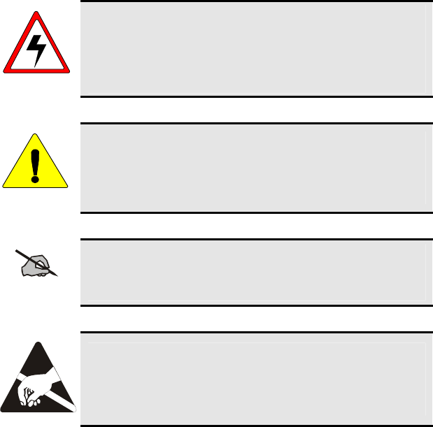
WARNING
The WARNING symbol calls attention to a procedure,
practice, or the like, which, if not correctly performed or
adhered to, could result in personal injury. Do not proceed
beyond a WARNING symbol until the conditions identified
are fully understood or met.
CAUTION
The CAUTION symbol calls attention to an operating
procedure, practice, or the like, which, if not performed
correctly or adhered to, could result in damage to the
equipment or severely degrade the equipment performance.
NOTE
The NOTE symbol calls attention to supplemental
information, which may improve system performance or
clarify a process or procedure.
The ESD symbol calls attention to procedures, practices, or
the like, which could expose equipment to the effects of
Electro-Static Discharge. Proper precautions must be taken
to prevent ESD when handling circuit modules.
7
OPERATING TIPS
Antenna location and condition are important when operating a portable radio.
Operating the radio in low lying areas or terrain, under power lines or bridges,
inside of a vehicle or in a metal framed building can severely reduce the range
of the unit. Mountains can also reduce the range of the unit.
In areas where transmission or reception is poor, some improvement may be
obtained by ensuring that the antenna is vertical. Moving a few yards in
another direction or moving to a higher elevation may also improve
communications. Vehicular operation can be aided with the use of an
externally mounted antenna.
Battery condition is another important factor in the trouble free operation of a
portable radio. Always properly charge the batteries.
EFFICIENT RADIO OPERATION
For optimum audio clarity at the receiving radio(s), hold the portable radio
approximately three inches from your mouth and speak into the microphone at
a normal voice level.
Keep the antenna in a vertical position when receiving or transmitting a
message.
Do not hold the antenna when receiving a message and, especially, do not
hold when transmitting a message.
WARNING
Do NOT hold onto the antenna when transmitting!
Antenna Care and Replacement
WARNING
Always keep the antenna at least 0.8 inches (2 cm.) away from
the body and 2 inches (5 cm.) from the face when transmitting
to ensure FCC RF exposure compliance requirements are not
exceeded.
WARNING
Do not use the portable radio with a damaged or missing
antenna. A minor burn may result if a damaged antenna comes
into contact with the skin. Replace a damaged antenna
immediately. Operating a portable radio with the antenna
missing could cause personal injury, damage the radio, and may
violate FCC regulations.
8
WARNING
Use only the supplied or approved antenna. Unauthorized
antennas, modifications or attachments could cause damage to
the radio unit and may violate FCC regulations. (Refer to Table
2: Options and Accessories.)
Electronic Devices
CAUTION
RF energy from portable radios may affect some electronic
equipment. Most modern electronic equipment in cars,
hospitals, homes, etc. are shielded from RF energy. However, in
areas in which you are instructed to turn off two-way radio
equipment, always observe the rules. If in doubt, turn it off!
Aircraft
WARNING
Always turn off a portable radio before boarding any aircraft!
• Use it on the ground only with crew permission.
• DO NOT use while in-flight!!
Electric Blasting Caps
WARNING
To prevent accidental detonation of electric blasting caps, DO
NOT use two-way radios within 1000 feet of blasting
operations. Always obey the "Turn Off Two-Way Radios"
signs posted where electric blasting caps are being used.
(OSHA Standard: 1926.900)
Potentially Explosive Atmospheres
WARNING
Areas with potentially explosive atmosphere are often, but not
always, clearly marked. These may be fueling areas, such as gas
stations, fuel or chemical transfer or storage facilities, and areas
where the air contains chemicals or particles, such as grain, dust,
or metal powders.
Sparks in such areas could cause an explosion or fire resulting in
bodily injury or even death.
Turn OFF two-way radios when in any area with a potentially
explosive atmosphere. It is rare, but not impossible that a radio
or its accessories could generate sparks.
9
BATTERY DISPOSAL
The P7100IP series portable radios use rechargeable, recyclable Nickel
Cadmium (NiCd) or Nickel Metal Hydride (NiMH) batteries.
NICKEL CADMIUM BATTERY
At the end of its useful life, under various state and local
laws, it may be illegal to dispose of Nickel Cadmium
b
atteries into the municipal waste stream. Check with local
solid waste officials for recycling options and proper
disposal. Call Toll Free 1-800-8BATTERY for
information and/or procedures for returning rechargeable
batteries in your state.
NICKEL METAL HYDRIDE BATTERY
There are no special requirements concerning the disposal of NiMH batteries.
Batteries can be recycled. Call Toll Free 1-800-8BATTERY for information.
10
11
INTRODUCTION
This manual describes how to use the P7100IP series portable radio. The
P7100IP series radios are synthesized, microprocessor-based, high
performance portable FM radios providing reliable two-way communications
in both the Enhanced Digital Access Communications Systems (EDACS®)
trunking environment and conventional communications systems.
In EDACS (trunked) mode, the user selects a communications system and
group. In this mode, channel selection is transparent to the user and is
controlled via digital communication with the system controller. This provides
advanced programmable features and fast access to communication channels.
In the conventional mode, the user selects a channel and communicates
directly on that channel. In this mode, a system refers to a set of channels. A
channel is a transmit/receive radio frequency pair.
The exact operation of the radio will depend on the operating mode, the
radio’s programming, and the particular radio system. Most features described
in this manual can be enabled through programming. Consult the particular
features programmed into the P7100IP.
For further detail about features and operation refer to the appropriate
maintenance manual or contact the system administrator.
WATER RESISTANCE
The P7100IP series portable radios operate reliably even under adverse
conditions. These radios meet MIL-STD-810F specifications for driven rain,
humidity, and salt fog.
OPTIONS AND ACCESSORIES
Table 2 lists the Options and Accessories tested for use with the P7100IP series
portable radios. Items for use with a specific band split or part number are
noted.
Refer to the maintenance manual or to M/A-COM’s Products and Services
Catalog for a complete list of options and accessories, including those items
that do not adversely affect the RF energy exposure.
WARNING
Always use M/A-COM authorized accessories (antennas,
batteries, belt clips, speaker/mics, etc). Use of unauthorized
accessories may cause the FCC Occupational/Controlled
Exposure RF compliance requirements to be exceeded. (Refer
to Table 2: Options and Accessories.)
CAUTION
Always use the correct options and accessories (battery, antenna,
speaker/mic, etc.) for the radio. Immersion rated options must
be used with an immersion rated radio. Intrinsically safe options
must be used with intrinsically safe radios. (Refer to Table 2:
Options and Accessories.)
Table 2: Options and Accessories
DESCRIPTION PART NUMBER
ANTENNAS
Antenna (136-151 MHz) KRE 101 1219/1
Antenna (150-162 MHz) KRE 101 1219/2
Antenna (162-174 MHz) KRE 101 1219/3
Antenna (378-403 MHz) KRE 101 1219/9
Antenna (403-430 MHz) KRE 101 1219/10
Antenna (378-430 MHz) KRE 101 1223/10
Antenna, Spring Whip (450-470 MHz) KRE 101 1219/12
Antenna, Spring Whip (470-512 MHz) KRE 101 1219/13
Antenna, Quarter Wave (450-512 MHz) KRE 101 1223/12
Flexible Gain Antenna (800 MHz) KRE 101 1506/1
Whip Antenna (800 MHz) KRE 101 1223/01
BATTERIES (IMMERSION-RATED)
7.5V Nickel Cadmium (NiCd) Battery BKB 191 210/3
7.5V Nickel Metal Hydride (NiMH) Battery BKB 191 210/4
7.5V NiCd Battery-Intrinsically Safe <IS> BKB 191 210/5
7.5V NiMH Battery-Intrinsically Safe <IS> BKB 191 210/6
BATTERIES (WIND DRIVEN RAIN)
7.5V NiCd Battery BKB 191 210/23
7.5V NiMH Battery BKB 191 210/24
7.5V NiCd Battery - <IS> BKB 191 210/25
7.5V NiMH Battery - <IS> BKB 191 210/26
Continued
12

13
DESCRIPTION PART NUMBER
MISCELLANEOUS ACCESSORIES
Speaker Mic <IS> KRY 101 1617/183
Speaker Mic Antenna Version Plus <IS> KRY 101 1617/184
Speaker Mic, Charger Compatible <IS> KRY 101 1617/185
Speaker Mic, Ant. Version, Charger Comp. <IS> KRY 101 1617/186
Speaker Mic, Immersible <IS> KRY 101 1617/283
Speaker Mic, Ant. Version, Immersible <IS> KRY 101 1617/284
Speaker Mic, Ant. Version, Immersible, Charger Comp. <IS> KRY 101 1617/287
Speaker Mic, Ruggedized <IS> KRY 101 1617/383
Speaker Mic, Ruggedized, Charger Comp., <IS> KRY 101 1617/385
Metal Belt Clip KRY 101 1647/1
Belt Loop with Swivel KRY 101 1609/1
Swivel (part of KRY 101 1639 and 1648) KRY 101 1608/2
Leather Case (Belt Loop type) KRY 101 1638/1
Leather Case with Swivel & Belt Loop KRY 101 1639/1
Nylon Case (Black) with Swivel & Belt Loop KRY 101 1648/1
Nylon T-Strap KRY 101 1656/1
Earpiece Kit for Speaker Mic <IS> RLD54107/11
Nylon Case (Orange) with Belt Loop KRY 101 1649/1
Speaker Mic, Industrial OT-V2-10121
Speaker Mic, Industrial PLUS OT-V2-10122
Earphone Kit, Black OT-V1-10520
Earphone Kit, Beige OT-V1-10521
Earphone Kit, Black OT-V1-10522
Earphone Kit, Beige OT-V1-10523
3-Wire Mini-Lapel (Beige) OT-V1-10524
3-Wire Mini-Lapel (Black) OT-V1-10525
Ultra-Lite Headset with Inline PTT OT-V4-10314
Liteweight Headset with Single Speaker OT-V4-10315
Over-the-Head Headset OT-V4-10316
Behind-the-Head Headset OT-V4-10317
ACCESSORIES APPROVED FOR USE ONLY WITH RU101219V71-V73
ANTENNA FOR RU101219V71-V73 ONLY
Whip Antenna (800MHz) KRE 101 1506/2
BATTERIES (IMMERSION-RATED) FOR RU101219V71-V73 ONLY
7.5V Nickel Cadmium (NiCd) Battery BKB 191 210/33
7.5V Nickel Metal Hydride (NiMH) Battery BKB 191 210/34
7.5V NiCd Battery-Intrinsically Safe <IS> BKB 191 210/35
7.5V NiMH Battery-Intrinsically Safe <IS> BKB 191 210/36
BATTERIES (WIND DRIVEN RAIN) FOR RU101219V71-V73 ONLY
7.5V NiCd Battery BKB 191 210/43
7.5V NiMH Battery BKB 191 210/44
7.5V NiCd Battery - <IS> BKB 191 210/45
7.5V NiMH Battery - <IS> BKB 191 210/46
MISCELLANEOUS ACCESSORIES FOR RU101219V71-V73 ONLY
Speaker Mic, Antenna Version, Ruggedized KRY 101 1617/384
Speaker Mic, Ant. Version, Ruggedized, Charger Comp <IS> KRY 101 1617/387
Swivel Mount Clip KRY 101 1608/3
Ranger Headset OT-V4-10421
Skull Microphone OT-V4-10428
Behind-the-Head Headset OT-V4-10450
Throat Microphone OT-V4-10656
USER INTERFACE
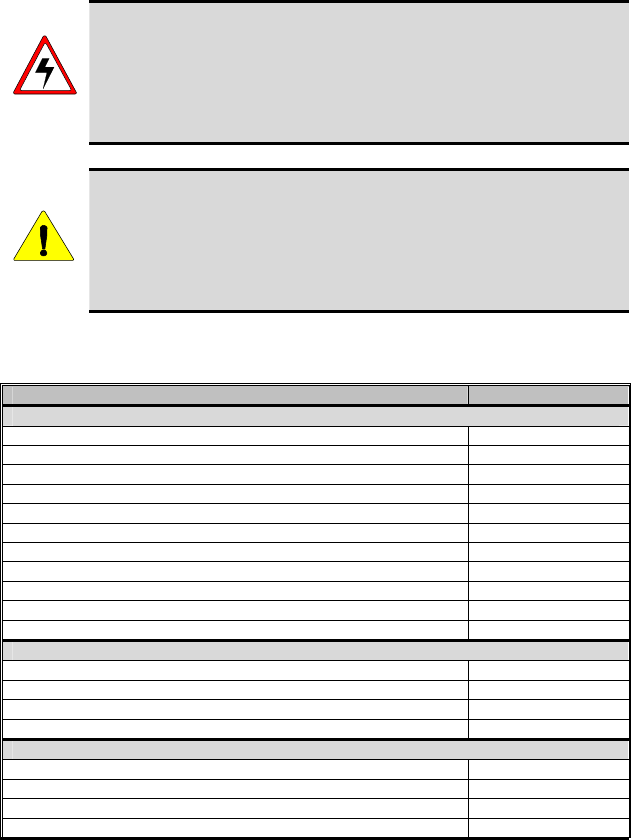
Figure 1: Top View
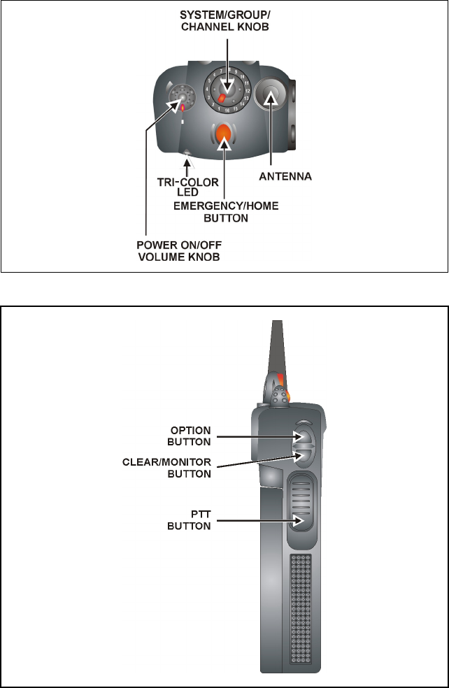
Figure 2: Side View
14
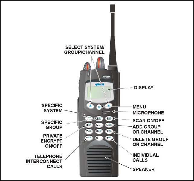
Figure 3: System Model
15
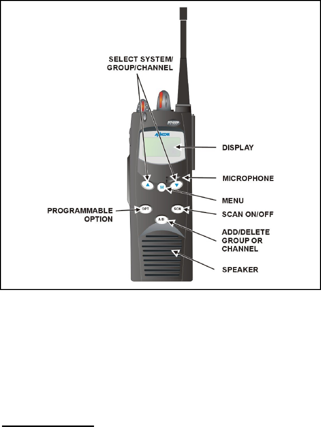
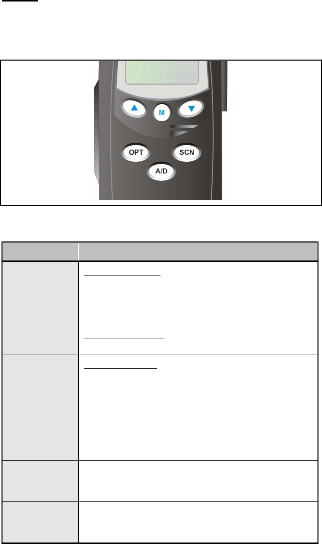
Figure 4: Scan Model
CONTROLS
The radio features two rotary control knobs and an emergency button mounted
on the top of the radio. Push-To-Talk, option and monitor buttons are
mounted on the side. The front mounted keypad has six buttons on the
P7150IP Scan model and 15 buttons on the P7170IP System Radio.
Buttons and Knobs
This section describes the primary function of the button and knob controls.
Other functions associated with these controls are detailed in later sections.
POWER ON-OFF
VOLUME KNOB Applies power to and adjusts the receiver’s volume.
Rotating the control clockwise applies power to the
radio. A single alert tone (if enabled through
programming) indicates the radio is operational.
Rotating the control clockwise increases the volume
level. Minimum volume levels may be programmed
16
17
into the radio to prevent missed calls due to a low
volume setting. While adjusting the volume the
display will momentarily indicate the volume level
(i.e. VOL=31). The volume range is from a minimum
programmed level of zero (displayed as OFF in the
display) up to 31, which is the loudest level.
CONTROL KNOB Selects systems or group/channels (depending on
programming). This is a 16-position rotary knob.
Note: A mechanical stop, which can limit the
positions accessed, is shipped with the radio but must
be installed. To install the mechanical stop, remove
the channel knob, loosen the set screw on the channel
knob metal base (using a 1.27mm hex wrench), and
remove the channel knob metal base. Replace the 16
channel ring with the channel stop ring located at the
desired channel. Reinstall the channel knob metal
base, tighten the set screw, and reinstall the channel
knob.
EMERGENCY/
HOME BUTTON Automatically selects the pre-programmed
Group/System by pressing and holding for a
programmed duration. It can also be used to declare
an emergency by pressing and holding for a
programmed duration. The button must be pre-
programmed for either operation, but not both.
PTT BUTTON Push-To-Talk must be pressed before voice
transmission begins. In trunked mode the radio’s ID is
transmitted upon depression of the PTT button. (Refer
to Figure 2 for location.)
CLEAR/MONITOR
BUTTON In trunked mode: Exits the current operation
(removing all displays associated with it) and returns
the radio to the selected talk group. Terminates
individual and telephone interconnect calls.
In conventional mode: Unsquelch the receiver and
allows channel monitoring prior to transmission.
Momentarily removes the Channel Guard decoding
from the channel.
OPTION BUTTON Activates one of a number of programmable software
options selected during PC programming.
Programmable options include hi/low power settings,
keypad lock, LCD contrast, LCD and keypad back
lighting.
Keypad
The keys on the Keypad have special functions and are labeled using a symbol
or abbreviated word describing its primary function. Numeric entry is a
secondary function of the keys. Each key is described in the following
subsections.
Figure 5: Scan Radio Front Panel
KEY FUNCTION
Primary Function: Allows the user to select system,
groups, or channels, depending on personality
programming. The buttons act as STEP UP or STEP
DOWN. Pressing one of these buttons displays the next
or previous stored system, group or channel.
Secondary Function: Changes the selection for an item
within a list.
Primary Function: Accesses the pre-stored menu. The
menu can include high/low power setting, keypad lock,
LCD contrast, LCD and keypad backlighting.
Secondary Function: Activates a selected item within a
list. After a menu list is accessed, scroll through the list
using the or keys and then activate specific
items with the key. This is similar to an “Enter” key.
(Scan only)
Adds/Deletes selected groups or channels from the Scan
list of the currently selected system.
(Scan only)
Turns the Scan operation ON and OFF.
18
19
KEY FUNCTION
(Scan only)
Activates one of a number of programmable software
options.
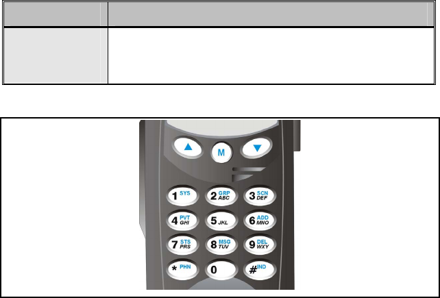
Figure 6: System Radio Front Panel

20
KEY FUNCTION
Same as Scan Model
Same as Scan Model
Selects a specific system. If the rotary knob is used to
select the system and more than 16 systems are
programmed in the radio, the key is used to select
additional banks (groupings) of systems.
1-9, *, 0, # These keys are used to place telephone interconnect and
individual (unit-to-unit) calls. The keys operate like a
normal telephone keypad.
Selects a specific group.
Turns the Scan operation ON and OFF.
Enables or disables Private Mode for the
system/group/channel displayed.
Adds groups or channels from the currently selected
system to the Scan list.
Status. Access to the status list (0-9). The Status key
permits the transmission of a pre-programmed status
message to an EDACS site.
Message. Access to the message list (0-9). The
Message key permits the transmission of a pre-
programmed message to an EDACS site.
Deletes selected groups or channels of the currently
selected system from the Scan list.
Places telephone interconnect calls.
Initiates individual calls.
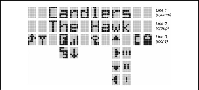
DISPLAY
The radio Display is made up of 3 lines (see Figure 7). Lines 1 and 2 contain
eight alphanumeric character blocks and are used primarily to display system
and group names. Line 1 also displays radio status messages. The 3rd line is
used primarily to display radio status icons. All three lines are used to display
menu options when in the menu mode. If programmed, the display
backlighting will illuminate upon power up or when radio controls are
operated.
Figure 7: Radio Display
21
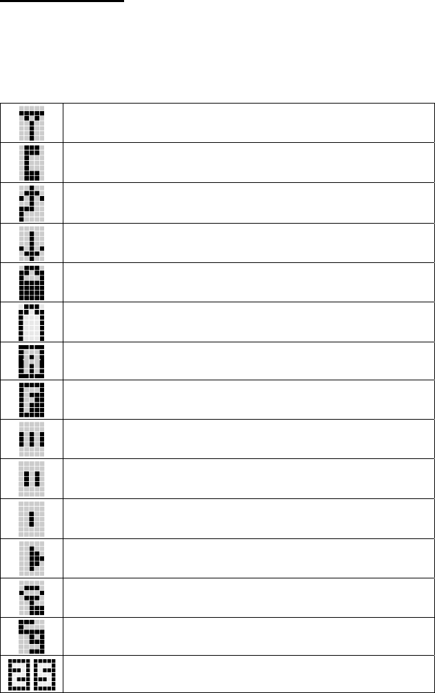
Radio Status Icons
Status Icons indicate the various operating characteristics of the radio. The
icons show operating modes and conditions and appear on the third line of the
display (see Table 3).
Table 3: Display Icons
Icon Descriptions
Steady – “Busy” transmitting or receiving
Flashing – call queued
Steady – special call mode (individual or telephone)
Steady – during all radio transmissions
Steady – transmit at low power
If icon is not visible – transmit at high power
Steady – battery charge indicator (refer to Figure 8)
Flashing – Low battery indicator (refer to Figure 8)
Steady – Indicates the current channel is set up as an analog channel.
Steady – trunked system in Failsoft™ mode
Steady – group or channel in scan list
Steady – priority 2 group or channel
Steady – priority 1 group or channel
Steady (rotates clockwise) – scan mode enabled
If icon is not visible – scan is disabled
Steady – transmit in encrypt mode
Flashing – receiving an encrypted call
Steady – Channel Guard enabled
If icon is not visible – Channel Guard is disabled
Steady – Indicates the current channel is set up as a Project 25 (P25)
channel.
22
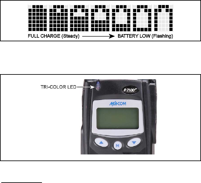
Figure 8: Battery Charge Icons (Full Cycle)
The battery icons (see Figure 8) indicate approximate level only, based on
battery voltage.
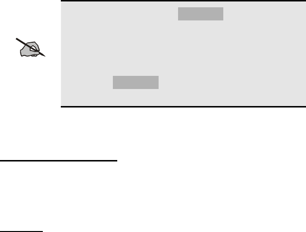
Figure 9: Tri-Color LED
Tri-Color LED
The Tri-Color LED changes color to indicate radio status and is visible from
both the front and top of the radio (see Figure 9). The three colors of the LED
and the status they represent are:
Green: Receiving
Red: Unencrypted transmission
Orange: Encrypted transmission
23

24
Status Messages
During radio operation, various radio Status Messages can be displayed. The
messages are described below.
MESSAGE NAME DESCRIPTION
QUEUED Call Queued Trunked mode only. Indicates the system has
placed the call in a request queue.
SYS BUSY System Busy Trunked mode only. Indicates the system is busy,
no channels are currently available, the queue is full,
or an individual call is being attempted to a radio that
is currently transmitting.
DENIED Call Denied Trunked mode only. Indicates the radio or talkgroup
is not authorized to operate on the selected system
and/or talkgroup.
CC SCAN Control
Channel Scan Trunked mode only. Indicates the control channel is
lost and the radio has entered the Control Channel
Scan mode to search for the control channel (usually
out of range indication).
WA SCAN Wide Area
Scan Trunked mode only. Indicates the radio has entered
the Wide Area Scan mode to search for a new system
(if enabled through programming).
TALKARND Talkaround Conventional mode only. Indicates the radio is
operating on conventional channels in talkaround
mode (no repeater).
SYSC ON System Scan
Features On Trunked mode only. Indicates the System Scan
features are enabled.
SYSC OFF System Scan
Features Off Trunked mode only. Indicates the System Scan
features are disabled.
LOW BATT Low Battery Battery voltage has dropped to the point to where the
radio is no longer able to transmit. The radio will still
be receive calls until the battery is discharged beyond
the point of operation upon which the radio will
automatically shutdown.
RXEMER Receive
Emergency Trunked and P25 modes only. Indicates an
emergency call is being received. This message will
be flashing on line two.
TXEMER Transmit
Emergency Trunked and P25 modes only. Indicates an
emergency call has been transmitted on this radio.
This message will be flashing on line two.
VOL=31 Volume Level Indicates the current volume level. The volume level
display ranges from OFF (silent) to 31 (loudest).
WHC Who Has
Called Trunked and P25 modes only. Indicates an
individual call has been received, but not responded
to. The indicator turns OFF if the individual call mode
is entered, the system is changed, or the radio is
turned off and then on again.
UNKNOWN Unknown ID Trunked and P25 modes only. Indicates an
individual call is being received from an unknown ID.

25
Error Messages
If either of the Error Messages shown below is displayed, the radio is
programmed incorrectly or needs servicing.
DSP ERR
ERR=XXXX
(PowerUp only)
or DIG V x
ERR x
Where: xxxx is the error code and DSP ERR or DIG V ERR is the
message.
ALERT TONES
The P7100IP radio provides audible Alert Tones or “beeps” to indicate the
various operating conditions (see Table 4).
Table 4: Alert Tones
NAME TONE DESCRIPTION
Call
Originate (B) one short mid-
pitched OK to talk after pressing the push-to-talk
button
Call
Queued (T) one high-pitched Call queued for processing
Autokey (T) one mid-pitched Queued call received channel assignment
System
Busy (T) three low-pitched System busy or unable to complete call
Call Denied (T) one low-pitched Radio is not authorized on the system or
group
Carrier
Control
Timer
(B) five high-pitched /
one long low-pitched PTT depressed for maximum length of time
Low
Battery (B) one low-pitched/
one short mid-
pitched
Low battery
TX Low
Battery
Alert
(B) one low-pitched After PTT - battery too low to transmit
(T) = trunked mode only (B) = both trunked and conventional modes
26
UNIVERSAL DEVICE CONNECTOR (UDC)
The Universal Device Connector (UDC) provides connections for external
accessories such as a headset or a speaker-microphone. The UDC is located
on the right side of the radio (opposite the PTT Button). When the radio is
locked in a vehicular charger the UDC provides the audio and control
connections between the radio and the vehicular charger. The UDC facilitates
programming and testing the radio. The UDC pins perform different
functions depending on the accessory attached to the UDC.

CONVENTIONAL OPERATION
In addition to the features covered in the following BASIC OPERATION
section, the following functions are for the conventional mode. The radio
functions in the conventional mode when using conventional communications
channels (non-trunked).
RECEIVING A CALL
1. Select desired conventional system and channel or turn scan ON and
make sure desired channel is in scan list.
2. When the radio receives a call, the radio will unmute and the channel
name will appear in the display.
SENDING A CALL
1. Select desired system and channel.
2. Ensure the channel is not busy by pressing the Clear/Monitor button
momentarily. If audio is heard or if the icon is on, the channel is busy.
3. When sure that the channel is not busy, press the Push-To-Talk button
and speak into the microphone.
27
BASIC OPERATION
TURNING ON THE RADIO
1. Power ON the radio by rotating the POWER ON-OFF/VOLUME knob
clockwise. A short alert signal (if enabled through programming)
indicates the radio is ready to use. Refer to Figure 1 for location of the
POWER ON-OFF/VOLUME KNOB.
2. The display shows the last selected system and group or a default system
and group (depending on programming).
3. Adjust the POWER ON-OFF/VOLUME knob to the desired volume
level.
4. Select the desired system and group. The display indicates the current
system and group names.
5. The radio is now ready to transmit and receive calls.
NOTE
In the trunked environment, CC SCAN will be displayed if
communication with the system's control channel cannot be
established. This may occur if, for example, the radio is out
of range of the trunking site. It may be necessary to move to
another location or select another trunking system to re-
establish the control channel link for trunked mode
operations. CC SCAN is displayed on the group line until
a control channel is accessed.
SYSTEM SELECTION
Method 1 (System Model)
1. Press
to access system list.
2. Press the numeric key, which is mapped to the desired system.
3. Press
. The radio will move to the selected system
Method 2
1. Rotate System/Group/Channel knob to desired system number position,
or
2. Press the
buttons to change systems. The display registers the
new system name on line one.
28

GROUP SELECTION
Method 1 (System Model)
1. Press
to access group list.
2. Press
to scroll through the list of groups or the numeric key
mapped to the desired group list.
3. Press
to select desired group. The radio will move to the selected
group.
Method 2
Rotate System/Group/Channel knob, or
If this knob is not programmed for groups, press the buttons to
change groups. The display registers the new system name on line two.
CHANNEL SELECTION
Rotate System/Group/Channel knob, or
If this knob is not programmed for channels, press the buttons to
change channels.
MODIFY SCAN LIST
System Model
1. Press
to toggle scan OFF and verify is not displayed.
2. Select group or channel.
3. Press
once to remove group or channel from list.
4. Press
once to add as a normal group or channel.
Press twice to add as a Priority 2 group.
Press three times to add as a Priority 1 group.
5. Press
to re-start scanning.
Scan Model
1. Press
to toggle scan OFF and verify is not displayed.
2. Select group or channel.
3. Press
once to remove group or channel from the list.
4. Press
once to add as a normal group or channel.
29

Press twice to add as a Priority 2 group.
Press three times to add as a Priority 1 group.
5. Press
to re-start scanning.
NUISANCE DELETE (SYSTEM MODEL)
A channel can temporarily be deleted from the scan list if it is not the
currently selected channel.
1. Turn Scan ON.
2. When the radio receives a call on the channel, press the . The
channel is removed from the scan list until the radio is power cycled.
BACKLIGHT ON/OFF
1. Press to access the menu.
2. Press
to scroll through menu until “BCKLGHT” appears.
3. Press
to select Backlight menu.
4. Press
to toggle backlight ON and OFF.
5. Press
to select new backlight setting.
CONTRAST ADJUST
1. Press to access the menu.
2. Press
to scroll through menu until “CONTRAST” appears.
3. Press
to select Contrast menu.
4. Press
to adjust contrast setting from 1 - 4.
5. Press
to select new contrast setting.
DECLARING AN EMERGENCY
1. Press and hold the red Emergency/Home button (the length of time is
programmable; check with the system administrator).
2. *TXEMER* will flash in the display, plus and will be displayed.
After 2-3 seconds the transmit icon will turn off.
30

31
3. *TXEMER* and will remain until the emergency is cleared.
4. Press the PTT and will reappear.
5. Release PTT when the transmission is complete.
LOCKING/UNLOCKING KEYPAD
1. Press button.
2. Within 1 second, press the Option button on the side of the radio.
HIGH/LOW POWER ADJUSTMENT
Transmit power adjustment is possible if enabled through programming.
Within conventional systems, transmit power is adjustable on a per channel
basis. Within EDACS trunking systems, transmit power is adjustable on a per
system basis.
There are two ways to toggle between high and low power:
Using the Menu Button:
1. Press
.
2. Using the
and keys, scroll until the cursor (>) appears to the left
of “TX POWER” in the display.
3. Press
again to toggle between High and Low power.
4. “POWER = HIGH” or “POWER = LOW” will appear momentarily on
the top line of the display.
Using the Pre-Programmed Option Button:
Press the Option button. “POWER = HIGH” or “POWER = LOW” will
appear momentarily on the top line of the display.
MENU
The Menu function accesses features that are not available directly from the
keypad. The order and actual menu items available is configurable through
programming. Upon radio power up, the menu item that is at the top of the
menu list will always be displayed first. Subsequent access to the menu
function will return the last menu item that was shown in the display and
cursor position.
1. To enter the menu mode, press .

2. Upon entering the menu selection mode, Menu options will appear on the
display (see Figure 10).
Figure 10: Menu Display
3. The radio will continue to receive and transmit normally while in the
menu function.
4. To scroll through the menu options use the or keys. When the
required menu item has been found align the cursor with the option then
press to select it. The menu item's parameter setting shown in the
display can now be changed by using or to scroll through the
list of parameter values. Once the desired setting is reached press to
store the value and return the menu option selection level. For menu items
that display radio information, pressing or will scroll through a
list of informational displays. The possible menu items are in Table 5.
An example of the menu item selection process and menu item parameter
change is detailed below for the backlight menu item.
1. PRESS:
The menu mode is entered.
2. PRESS:
or until the display shows:
3. PRESS:
The backlight menu item is activated. Line one shows the active menu
item and its current parameter setting. Line two shows the currently
selected system or group name (see Figure 11).
Figure 11: Backlight Menu Display
32

4. The menu item's parameter setting shown in the display can now be
changed by using or .
5. Once the desired setting is reached press to store the value and return
the menu option selection level.
For menu items that display radio information pressing or will scroll
through a list of informational displays. An example of information displays is
shown in Figure 12.
NOTE
The TX POWER menu item, when selected, toggles
LOW/HIGH power. It does not use or to scroll nor is
an additional press of the button required.
Table 5: Menu Item Information
FEATURE DISPLAY PARAMETER
SETTING COMMENT
Keypad Lock Menu Item:
KEY LOCK
Once Selected:
LOCKED
Locked
Unlocked Locks the keypad. To
unlock; press and
release “M” then within
1 second press the
option button (NOTE:
this sequence is also a
short cut to locking the
keypad.)
Backlight
Adjust Menu Item:
BCK LIGHT
Once Selected:
BCKL=
OFF/ON Selects the light level
for backlighting.
Contrast
Adjust Menu Item:
CONTRAST
Once Selected:
CNTRST=
1, 2, 3, 4 Selects the display
contrast level.
Transmit
Power
Select
Menu Item:
TX POWER
Once Selected:
POWER=
HIGH or LOW Selects radio output
power mode.
Radio
Revision
Information
Menu Item:
REVISION N/A Selects the information
display to view.
Informational display
only (see Figure 12).
No user selectable
settings.
33

34
FEATURE DISPLAY PARAMETER
SETTING COMMENT
Toggle Scan
On/Off SCAN ON/OFF Toggles Scan
operation ON/OFF.
Toggle
Private
Mode
PRIVATE ON/OFF Toggles Private Mode
ON/OFF.
Display
Current
Encryption
Key
DISP KEY N/A Displays current
encryption key.
Informational display
only. No selectable
settings.
Display
Current
Home
Group/Chan
nel
HOME N/A Selects Home
Group/Channel
Select
Desired
System
SYS SEL N/A Selects a new system.
Add
Group/Chan
nel to Scan
List
SCAN ADD N/A Adds to Scan List.
Delete
Group/Chan
nel
SCAN DEL N/A Deletes Group or
Channel from Scan
List.
Add/Delete
Scan List SCAN A/D N/A Add or Delete from
Scan List.
Select
Telephone
Numbers
From Phone
List
PHN CALL N/A Trunked Only.
Data
Operation NO DATA ON/OFF Trunked Only. Toggles
Data Operation
ON/OFF.
Select
Individual
Call from IC
List
IND CALL N/A Trunked Only.
Select
Group GRP SEL N/A Trunked Only.

35
FEATURE DISPLAY PARAMETER
SETTING COMMENT
Talkaround TALKARND ON/OFF Conventional Only.
Toggles Talkaround
feature ON/OFF.
Select
Channel CHN SEL N/A Conventional Only.
Feature
Encryption
Display
Menu Item:
FEATURES
Once Selected:
(See Feature
Encryption
Display
Section)
N/A Indicates current
features programmed
into the radio as well as
certain information
required to add
features to the radio.
Informational display
only. No user
selectable settings.
System
Scan Enable Menu Item:
SYS SCAN
Once Selected:
SYSC ON or
SYSC OFF
ON/OFF System Scan features
are toggled ON and
OFF.
PRS - NAME
XXXXXXXX Personality Name
EEPR SIZ EEPROM Size
RAM SIZ RAM Size
FLSH SIZ Flash Size
RF BAND Frequency Band
HSD RATE Data Transfer Rate
PRS VER Software Version
DSP_ _RAM DSP Software Version
FLSH - VER FLASH Software
r - released, 01A - revision state
M/A-COM
(C) – 2003-2004 Copyright
Figure 12: Information Display
DIGITAL VOICE OPERATION
Digital voice programmed systems have three (3) different voice modes: clear
(analog), digital, and private (encrypted). The voice modes are programmed
on a per-group basis within each trunked system and on a per-channel basis
within each conventional system.
Clear Mode
The Clear Mode is a voice mode in which the radio transmits and receives
only clear (analog) voice signals. These analog signals are non-digitized and
non-encrypted. Clear mode transmissions can be monitored easily by
unauthorized persons.
NOTE
Groups or channels programmed for clear operation cannot
transmit or receive digital or private messages.
Digital Mode
The Digital Mode allows the radio to transmit and receive digitized voice
signals. Digital signals provide improved weak signal performance and cannot
be easily monitored with a standard receiver. Groups and channels
programmed for digital operation transmit only digital signals. Message
trunked group calls and individual phone calls (I-Calls) are answered back in
the mode in which they were received assuming the call or hang time is still
active. Individual phone, all call, and emergency calls are transmitted clear if
the digital mode is disabled or inoperative.
1. If receiving an analog message trunked call, the radio responds in the
analog mode during the hang time on the working channel.
2. If receiving an analog I-Call, the radio responds in the analog mode
during the hang time.
3. When using the *WHC* feature to respond to an I-Call (after the hang
time has expired), the call is transmitted in the mode defined by the
system mode as programmed for the current system if the ID being called
is not in the I-Call list. If the ID is in the I-Call list, then the call is
transmitted as defined by the I-Call mode programmed in the list for that
ID.
The overdial DTMF tones are not available while in the Digital Mode.
Private Mode
The Private Mode allows the radio to transmit encrypted messages and receive
clear or private transmissions. The radio transmits private if the group/channel
is programmed for private operation and forced operation is pre-programmed.
If autoselect operation is pre-programmed and the radio is in the Private
Mode, the radio transmits in the mode of the received call if the hang time is
active. If no hang time is active, the radio transmits private.
Cryptographic keys are transferred to the radio using a cryptographic
Keyloader. Up to seven (7) different cryptographic keys, numbered 1-7, can
be transferred from a Keyloader and stored in the radio. An individual key is
36
automatically selected on a per-group/channel basis according to the radio
programming. Groups and channels within the digital system can be
programmed for keys 1-7 (private). Up to 8 banks of 7 keys can be stored for
private systems. The bank is specified per system.
When operating on a group or channel programmed for Private Mode, all
transmissions are private transmissions and the radio receives clear and
private signals. The status icon is displayed when the Private Mode is
enabled. If the selected group or channel is programmed for auto-select
capability, the mode may be toggled between private and clear with the
key, then following the selection mode rules. Radios programmed for forced
private operation do not allow a change of the transmit mode.
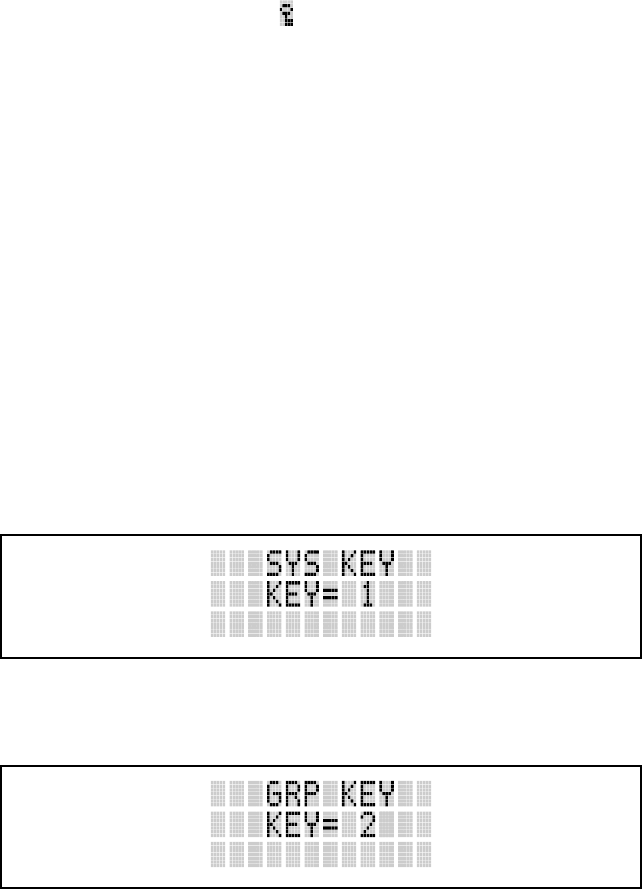
Displaying the Currently Used Cryptographic Key Number
To Display the Currently Used Cryptographic Key Number for either the
system encryption key (for special call such as individual, phone, all, agency
or fleet) or the group/channel key (for group or conventional calls), perform
the following procedure:
1. Press the
button.
2. Use the
or button to select "DISP KEY."
3. Then use the or button to toggle between displaying the system
key or the group/channel key.
System Encryption Key
Figure 13: System Encryption Key Display
Group/Channel Encryption Key
Figure 14: Group/Channel Encryption Key Display
37

Key Zero
All cryptographic keys can be zeroed (erased from radio memory) by pressing
the MONITOR/CLEAR button and while still pressing this button, press and
hold the OPTION button. Press both buttons for 2 seconds. A series of beeps
will begin at the start of the 2 second period and then switch to a solid tone
after the keys have been zeroed. The display will indicate KEY ZERO.
If the cryptographic key(s) are zeroed, one or more keys must be transferred
from the Keyloader into the radio before private communications may
continue.
Private Operation
Receiving an Encrypted Call
When receiving, the radio automatically switches between clear or private
operation. If the transmission being received is an encrypted transmission, it
will be decrypted, the icon is displayed, the receiver will unsquelch and the
message will be heard in the speaker. For this to occur the selected group or
channel must be programmed for private operation and the correct
cryptographic key must be loaded into the radio.
Transmitting an Encrypted Call
1. Select the desired group or channel
2. Place the radio in Private Mode by pressing key, then follow the
selection mode rules. On a System radio, the key can be used to
toggle the Private Mode ON/OFF. When Private Mode is enabled, the
icon is displayed.
If the last state of the radio was Private Mode, the Private Mode will be
enabled on power up. Also, the Private Mode will be enabled if forced
operation has been programmed in the radio.
If a group or channel is not programmed for Private Mode operation,
PVT DIS will be displayed if an attempt is made to enable private
transmit mode. It is not possible to operate on this group/channel in
Private Mode.
If the radio does not have the correct encryption key loaded, NO KEY#
will be displayed and the call will not be transmitted.
3. Continue with standard transmission procedures. A Private Mode access
tone will be heard when the PTT button is pressed.
38
Scanned Group Calls
Receiving a Scanned Group Call is the same as receiving a selected group
call. During the scan hang time, if the radio was programmed for autoselect, it
will transmit back in the same mode it received the call. For example, if a
clear group is entered in the scan list, it will only receive clear calls. If the
same group was available in private and entered in the scan list, it can receive
clear and private calls, provided autoselect was programmed in the radio. The
user can select transmitting on the scanned or selected group. If a group is
entered in the scan list more than once and in different modes (clear, digital,
private), only the first occurrence of the group will be used.
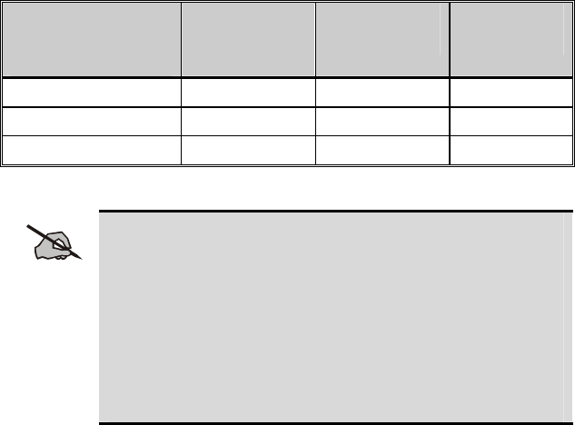
Table 6: Transmit/Receive Mode Compatibility for Digital Voice
Operation
GROUP/CHANNEL
PROGRAMMING
(TRANSMIT)
CLEAR
RECEIVE DIGITAL
RECEIVE PRIVATE
RECEIVE
CLEAR Yes No No
DIGITAL Yes Yes No
PRIVATE Yes No Yes*
*assumes the proper cryptographic key is loaded
NOTE
Conventional Digital or encrypted channels require Channel
Guard on the channel to operate correctly. The voice coding
technology embodied in this product is protected by
intellectual property rights including patent rights, copyrights,
and trade secrets of Digital Voice Systems, Inc. The user of
this technology is explicitly prohibited from attempting to de-
compile, reverse engineer, or to disassemble the Object Code,
or in any other way convert the Object Code into a human-
readable form.
39

TRUNKED OPERATION
SCANNING TRUNKED GROUPS
Groups that have been previously added to the scan list on a per system basis
may be scanned. Each system's group scan list is retained in memory when the
radio is powered OFF or when the battery pack is removed.
The following procedures outline scan operations for trunked groups. See the
conventional mode operating procedures for specific procedures on
conventional channel scanning.
Turning Scan On and Off
1. Toggle Scan operation ON by pressing (Scan model) or (System
model). icon rotates clockwise to indicate radio is scanning.
2. Toggle Scan operation OFF by again pressing (Scan model) or
(System model). will disappear.
• If the radio scans to a group other than the selected group then
receives a call on the selected group, the radio will switch to the
selected group. However, if the “scanned-to” group is programmed
at a higher priority the radio will remain on the “scanned-to” group.
• The radio will continue scanning if a new group is selected when
scan is ON.
Pressing the PTT button when scan is ON will cause the radio to transmit on
the displayed group or to the currently selected group (depending on
programming).
Adding Groups to a Scan List
Scan Model
1. Scan must be OFF to add/delete groups to/from the scan list. If the Scan
icon is ON, press the key to turn Scan OFF.
2. Select the desired group using the SYSTEM/GROUP/CHANNEL knob
and/or the or keys. If the selected group is currently on the list,
pressing will display on line three.
3. If the scan list status icon is blank ( ), the group can be added to the scan
list by pressing the key. will be displayed on line three.
40
4. Press the
key a second time to set the group to Priority 2. A is
displayed on line three.
Press a third time to set the group to Priority 1. A is displayed on line
three. The priority level section sequence only advances the group to the next
high priority level and stops at priority level 1. To select a lower priority level,
the group must be deleted from the scan list and then added back to the scan
list. Each new group added to the scan list starts at the lowest priority. If the
priority 1 and Priority 2 groups are already set and a new group is assigned as
Priority 1 or Priority 2, the previously assigned group will change to non-
priority scanning. One of the following messages may be momentarily
displayed:
SCAN DIS The radio is not programmed to scan.
FIXED P1 A Priority 1 group has been pre-
p
rogrammed into the radio. A
new Priority 1 group cannot be selected.
FIXD LST A fixed scan list has been pre-
p
rogrammed into the radio. It is
not possible to change the list without reprogramming the radio.
NOTE
To quickly view multiple group scan status, press then
slowly but consistently rotate the group knob. Each group
status will appear on the display.
System Model
1. With scan operation turned OFF, select the desired group to add to the
selected trunked system group scan list.
2. Press
. The current priority status of the group will be displayed in
column 10 of line three for a time-out period. If the group is not part of
the scan list the status will be blank.
3. While the status is displayed, press to add the group to the scan list.
is displayed on line three.
4. Press
a second time to set the group to Priority 2. A is displayed on
line three.
41
Press a third time to set the group to Priority 1. A is displayed on line
three. The priority level selection sequence only advances the group to next
higher priority level and stops at priority level 1. To select a lower priority
level, the group must be deleted from the scan list and then added back to the
scan list. Each new group added to the scan list starts at the lowest priority. If
the Priority 1 and Priority 2 groups are already set and a new group is assigned
as Priority 1 or Priority 2, the previously assigned group will change to non-
priority scanning. One of the following messages may be momentarily
displayed:
SCAN DIS The radio is not programmed to scan.
FIXED P1 A Priority 1 group has been pre-
p
rogrammed into the radio. A
new Priority 1 group cannot be selected.
FIXD LST A fixed scan list has been pre-
p
rogrammed into the radio. It is
not possible to change the list without reprogramming the radio.
NOTE
To quickly view multiple group scan status, press either or
the key. Then slowly but consistently rotate the group
knob. Each group status will appear on the display.
Deleting Groups from a Scan List
Scan Model
1. With scan operation turned OFF, select the desired group to delete from
the selected trunked system group scan list.
2. Press
. The current status of the group is displayed for a time-out
period.
While the current status is displayed, press . until the group from the scan
list is "blank". The sequence is "blank", , , ,"blank". Any group that is
not in a trunked system group scan list will show a "blank" for the time-out
period when it is the selected channel.
System Model
1. With scan operation turned OFF, select the desired group to delete from
the selected trunked system's group scan list.
2. Press
. The current status of the group is displayed for a time-out
period.
42

While the status is displayed, press to delete the group from the scan list.
, ,or turns OFF. Any group that is not in a trunked system group scan
list will show a "blank" for the time out period when it is the selected channel.
Nuisance Delete
A group can also be deleted from the scan list, if it is not the currently selected
group, by pressing the key (Scan model) or the key (System model)
during scan operation while the radio is displaying the unwanted group. The
group will be deleted from the system's group scan list in the same manner as
if done using the steps above. Deletions done in this manner will not remain
deleted if the radio is powered OFF and then powered ON.
SCANNING TRUNKED SYSTEMS
The radio can be programmed with the following System Scan features. These
features are automatically enabled when the radio is powered ON. A key or
menu option is also defined to allow the System Scan features to be toggled
during radio operation. This is covered in the Menu Selection and Pre-
Programmed Keypad Key sections. The System Scan state will be maintained
through system changes but will default to ON when the radio is powered ON.
Wide Area System Scanning
The P7100IP series radios can be programmed for Wide Area System Scan
operation for roaming across mobile systems. Upon the loss of the currently
selected system's control channel, radios can be programmed to automatically
scan the control channels of other systems. If a new control channel is found,
the radio will switch to the new system and sound an alert tone.
Priority System Scan
The radio can also be programmed for Priority System Scan. The priority
system is the desired or preferred system. While receiving the control channel
of the selected system, the radio will periodically leave the selected system
and search for the control channel of the priority system. This is done at a
programmable rate defined by the value in the Priority Scan Time control
(unless the ProScan™ algorithm is enabled, as explained in the following
sections). This priority scan timer is reset each time the PTT button is pressed
or when the call is received. If the priority system control channel is found, (or
meets the predefined criteria <ProScan>), the radio will automatically switch
to the priority system.
Enabling the Wide Area System Scan Function
If the radio cannot find the control channel of the selected system and begins
to wide area system scan, the radio will only scan for the priority system
control channel if the priority system is in the wide area scan list.
43

44
When ProScan is Enabled
The radio monitors the priority system and will switch to the priority system if
the criteria defined by the controls in the ProScan Options dialog box are met.
If ProScan is enabled, the rate at which the radio will scan for the priority
system is defined by the System Sample Time control, located in the ProScan
Options dialog box.
ProScan
The radio may be programmed for ProScan system scan operation for multi-
site applications depending on the version of radio flash code. ProScan is an
improved multi-site system scanning algorithm designed to replace
ProSound™ scanning. ProScan provides the radio with the ability to select a
new system for the radio to communicate on, when the selected system drops
below a predefined level. This is accomplished by enabling each radio to
analyze the signal quality of its current control channel and compares it with
the signal quality of the control channel for each site in its adjacent scan list.
(The signal quality metric used for the ProScan algorithm is based on a
combination of both Received Signal Strength Indicator (RSSI) and Control
Channel Verification (CCV) measurements.) When the selected system
degrades to a pre-programmed level, the radio will begin to look for a better
control channel. Once a control channel that exceeds the pre-programmed
parameters is found, the radio will change to the new system and emit a tone
(if enabled through programming). If the control channel is completely lost,
the radio will enter Wide Area System scanning and search the programmed
adjacent systems until a suitable control channel is found.
Menu Selection
Press and then use the or buttons to scroll through the selections
until SYS SCAN is displayed. Then press to toggle the System Scan
state. The SYSC ON or SYSC OFF display message is displayed for two
seconds to show the new state.
Pre-Programmed Keypad Key
Press the key pre-programmed to toggle System Scan and the SYSC ON or
SYSC OFF display message is displayed for two seconds to show the new
state.
EMERGENCY OPERATION
The radio's ability to declare an emergency, clear an emergency, remain
locked on an emergency system and group, and the emergency audio and
display freeze can each be enabled or disabled through programming. When
an emergency is declared scanning will stop and restarts only after the
emergency has been cleared.
Receiving an Emergency Call
When Receiving An Emergency Call on the selected group and system, an
alert beep is heard and is displayed. The message *RXEMER* flashes in
the display on line two until the emergency condition is cleared.
Declaring an Emergency Call
To send an emergency call to a selected system and group (or on an optionally
pre-programmed group), proceed as follows:
1. Press and hold the red EMERGENCY button that is on top of the radio in
front of the antenna for approximately one second (this time is
programmable and therefore could be longer or shorter; check with the
system administrator). The radio will transmit an emergency call request
with the radio ID until an emergency channel assignment is received.
2. When the working channel assignment is received, the radio sounds a
single beep indicating the radio has auto keyed (see Table 4) and is ready
for voice transmission. *TXEMER* flashes on line two in the display
until the emergency is cleared.
3. Press PTT and speak into the microphone in a normal voice. and
momentarily turn ON.
4. Release PTT when the transmission is complete.
To clear the emergency first press and hold the CLEAR/MONITOR button.
While continuing to hold the CLEAR/MONITOR button, press the
EMERGENCY button. (This will work if the radio is programmed to clear
emergencies.)
INDIVIDUAL CALLS
Receiving and Responding to an Individual Call (Trunked Mode
Only)
When the radio receives an individual call (a call directed only to the user's
radio), it un-mutes on the assigned working channel and displays . The first
line on the display shows the logical ID number of the unit sending the
message, or the associated name if the ID number is found in the individual
call list. The radio can be programmed to ring when an individual call is
received. If enabled, the ring begins five seconds after the caller un-keys and
will continue until the PTT button, the CLEAR/MONITOR button or the
individual call mode is entered.
NOTE
The volume of the ring is adjustable through the volume control
levels.
45
If a response is made by pressing the PTT to the call prior to the programmed
call-back time-out, the call will automatically be directed to the originating
unit. If a response is not made before the call-back time-out, the radio will
return to normal receive display, and *WHC* will appear on the first line of
the LCD.
To respond after the call-back time-out, press the key. The radio's display
will show the callers ID on the first line and WHCI=1 on the second line.
Pressing the PTT button at this point will initiate an individual call back to the
original caller.
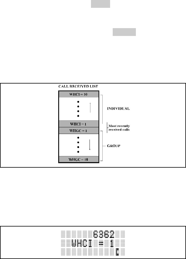
The radio stores the IDs of the last 10 callers in the Calls Received List as
shown. Individual calls are stored in the top half of the list (1-10) and Group
calls are stored in the bottom half of the list (1-10). The most recent call is
stored in position 1, the second most recent call is stored in position 2, etc.
Figure 15: Calls Received Lists
To access this list, press the key twice. Use the or buttons
or buttons to scroll through the list. Pressing the key will display the
time elapsed since the call was received. After pressing an example of the
display is as follows:
Figure 16: WHC Individual Call Display
Pressing PTT will initiate an individual call to the displayed logical ID.
Powering the radio OFF and ON will clear this list.
46

Sending an Individual Call (Trunked Mode Only)
Pre-Stored Individual Calls
The following procedures describe how to initiate and complete a Pre-Stored
Individual Call.
System Model
1. To select a pre-stored individual phone number, enter the individual call
mode using the key. is displayed. Then scroll through the list of
stored numbers using the or key.
2. Press the PTT button; when the radio is clear to transmit, turns ON,
turns OFF and the channel access tone sounds. Line one shows the called
individual's name if found in the list of stored individuals or LID
followed by the logical ID number of the unit being called. The message
*INDV* displays on line two.
Scan Model
1. To select a pre-stored individual number, enter the menu mode by using
the key. Scroll through the mode list using the or key.
2. Press
. is displayed. Scroll through the list of stored phone numbers
using the or key until the desired number is displayed. Press .
3. Press the PTT button; when the radio is clear to transmit turns ON,
turns OFF and the channel access tone sounds. Line one shows the called
individual's name or LID. The message *INDV* displays on line two.
Direct Dial Individual Calls (System Mode Only)
The following procedures describe how to initiate and complete a Direct Dial
Individual Call.
1. The individual call ID is not stored in the pre-stored list of call IDs but
the individual unit ID is known, it can be entered directly from the
keypad.
2. Press and hold the PTT button to transmit. will turn ON, will turn
OFF, and the channel access tone will sound. Line one shows the called
individual's ID followed by the logical ID number of the unit being
called. The message *INDV* displays on line two. Proceed talking into
the microphone.
47
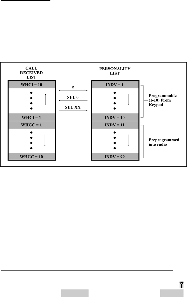
Call Storage Lists
There are two lists available for call storage in the P7100IP series radios, the
calls received list (1 - 10) and the personality list (1 - 99 as defined by the
user). When the individual call mode is entered by pressing , the calls
received list is available. The user can toggle to the personality list by
selecting any index other than 0 or toggle between the two lists by pressing
the key. If wrap is enabled, the calls received list wraps on itself and not
into the other list.
Figure 17: Calls Received and Personality Lists
The saved call list shows all ten storage locations. If no calls have been
received, the saved call list will be empty and the pre-stored list will be
available upon entering the individual call mode.
When in the saved call list, pressing the key toggles the time stamp ON
and OFF. The time stamp indicates how long ago the call was received. When
in the pre-stored list pressing the key toggles the Logical IDentification
(LID) ON and OFF.
TELEPHONE INTERCONNECT CALLS
Receiving a Telephone Interconnect Call (Trunked Mode Only)
When the radio receives a telephone interconnect call (a call directed only to
the user's radio), it un-mutes on the assigned working channel and displays .
The first line displays *PHONE*. The second line displays *INDV*.
Proceed with the call. Press PTT to talk, release PTT to listen.
48

Sending a Telephone Interconnect Call (Trunked Mode Only)
Pre-Stored Number
Use the following procedures to initiate and complete a Telephone
Interconnect call:
1. System Model: To select a previously stored phone number, press .
Use the or keys to scroll through the list of stored numbers.
Scan Model: To select a previously stored phone number, press . Use
the or keys to select the menu option PHN CALL. Press the
key again then use the or keys to scroll through the list of pre-
stored numbers.
2. Press and release the PTT button. When the radio is clear to transmit,
turns ON, turns OFF and the channel access tone sounds. Line one shows
the accompanying name selected from the list of stored numbers. The
message *PHONE* displays on line two. The radio then automatically
transmits the programmed number stored in the special call queue.
3. A telephone ring will be heard from the speaker. When someone answers
the phone, press the PTT button and speak into the microphone. Release
the PTT button to listen to the callee. Unsuccessful interconnect signaling
returns the radio to the normal receive mode and the number remains
displayed until the special call is cleared or the time-out expires or
another group or system is selected. Terminate a call by pressing the
CLEAR/MONITOR button.
NOTE
In half-duplex mode, only one person may talk at a time. The
radio PTT button needs to be pressed in order to communicate
to the individual called and released for the individual called to
be heard.
Direct Dialing of Phone Calls (System Mode Only)
1. If the phone number is not stored in the pre-stored list of phone numbers,
but the phone number is known, it can be entered directly from the
keypad. Start by pressing the . Then enter the required number from
the keypad.
NOTE
The last number directly entered can be recalled by first
pressing then pressing the PTT button.
49

2. If the phone number is not stored in the pre-stored list of phone numbers,
but the phone number is known, it can be entered directly from the
keypad. Start by pressing the . Then enter the required number from
the keypad.
3. A telephone ring can be heard from the speaker. When someone answers
the phone, press the PTT button and speak into the microphone. Release
the PTT button to listen to the individual called. Unsuccessful
interconnect signaling returns the radio to the normal receive mode and
the number remains displayed until the special call is cleared or the time-
out expires or another group or system is selected.
NOTE
In half-duplex mode, only one person may talk at a time. The
radio PTT button needs to be pressed in order to communicate
to the individual called and released for the individual called to
be heard.
4. To terminate the call, momentarily press the CLEAR/MONITOR button.
Dual-Tone Multi-Frequency: Overdial/Conventional Mode
Once the radio has established a connection to the public telephone system, it
may be necessary to “over-dial” more digits to access banking services,
answering machines, credit card calls, or other types of systems that require
Dual-Tone Multi-Frequency (DTMF) access digits.
Overdial operation can also be used to initiate a telephone interconnect call
via DTMF signalling if a dial tone has already been accessed on the system.
This method makes a telephone interconnect call while operating in the
conventional mode but will also function in trunked mode if a dial tone is
directly accessible.
Telephone numbers and other number sequences for overdialing can be stored
in the phone list when programming the radio. These numbers are accessed
by pressing , then following the selection mode rules. The following steps
are required to dial these numbers:
Scan Model
1. Follow the procedure in Sending A Telephone Interconnect Call
(Trunked Mode Only) to establish a connection to the telephone system
or consult the system administrator for the procedure to access a dial tone
on the trunked or conventional system.
2. Overdial numbers are transmitted by entering the phone mode using the
button.
50

Press to enter the overdial select/entry mode and follow the selection mode
rules to call up a stored number from the phone list. is displayed. Press PTT
to send the overdial sequence once. If the number needs to be transmitted
again it must be selected or entered again (this prevents unwanted numbers
from being sent the next time the PTT button is pressed during the call). This
overdial select/entry mode remains active until the call is dropped, cleared, or
is pressed. The overdial select/entry mode can be re-entered if the call is
still active by pressing .
System Model
1. Follow the procedure in Sending A Telephone Interconnect Call
(Trunked Mode Only) to establish a connection to the telephone system
or consult the system administrator for the procedure to access a dial tone
on the trunked or conventional system.
2. Overdial numbers are transmitted using either method as follows:
This overdial select/entry mode remains active until dropped, cleared, or is
pressed. The overdial select/entry mode can be re-entered if the call is still
active by pressing .
PROGRAMMABLE ENTRIES
Pre-Storing Individual and Telephone Interconnect Calls from the
Keypad (System Mode Only)
Individual Call ID numbers, telephone numbers and other number sequences
for overdialing are stored in the special calls lists when programming the
radio. The first ten entry locations of these lists can be changed by the radio
operator. The keypad is used when adding, changing, and storing numbers in
these entry locations.
Use the following procedure to store a number in one of the first ten entries of
a special call list:
1. Press
or to enter the individual call list or the phone call list.
is displayed.
2. Scroll through the list using the or until one of the first ten
entries is reached. NO ENTRY is displayed if the location is empty.
3. Enter the desired number. If necessary, a pause can be entered by pressing
and holding 0-9, , or until an underscore appears in the display
(telephone interconnect only). The individual call list entries will accept
up to 5 digits. The phone call list entries accept a combination of up to 31
digits and pauses.
51

52
4. Press and hold until the display changes indicating that the number
has been stored.
Repeat steps 1-4 above if the number stored in an entry location needs to be
changed.
STATUS/MESSAGE OPERATION
Status operation permits the transmission of a pre-programmed status
condition to the EDACS site. Message operation permits the transmission of a
pre-programmed message text to an EDACS site.
Status Operation
To send a status condition, press the key followed by or key to
select the pre-programmed status. STATUS and 0 through 9 pre-programmed
status selections are available from the menu. If STATUS is selected you need
to enter the number of the status message you intend to transmit. If no status
has been programmed for the selected number key, the radio will display NO
ENTRY. A valid selection will permit the status text to appear in the display
for a pre-programmed time. After the time-out expires or the key has been
pressed (the key will override the time-out period), the status is selected
and will be transmitted to the site or stored in the radio memory where it can
be polled by the site at a future time. Status messages can also be programmed
for single key operation so that a single press of a key assigned to a status
message automatically transmits that message. If the site does not receive the
status properly, the radio will sound a low pitched tone.
The status selection can also be canceled by pressing the CLEAR button prior
to the time-out period.
To view the currently selected status after it has been transmitted, press the
key and then the key to ramp to STS, re-press the key again and then
the CLEAR button prior to the time-out period. If the status was not sent
successfully to the site, the text associated with the status will flash in the
display.
Message Operation
Message Operation is performed in the same manner as status operation in the
previous section.
Dynamic Regroup Operation
Dynamic Regroup Operation permits multiple talk groups (up to eight) to be
added to a radio via the system manager. The radio must be pre-programmed
to respond to regrouping. Dynamic regrouping will not be activated in a radio

53
until the system manager sends an activation message. Each radio that
receives and acknowledges the regrouping instructions is successfully
regrouped.
Pressing and holding the CLEAR/MONITOR button for 2.5 seconds toggles
the user into and out of the dynamic regroup groupset. A double beep will
sound for entry or exit. The display will indicate REGRP_0x where "x" is a
digit of 1 to 8 indicating the group (when dynamic regroup has been enabled
by the user). If the radio is in dynamic regroup and the user selects a group
that has not been regrouped, the display will show NO ENTRY. The radio
will be prevented from transmitting and receiving calls in this condition
except for scanned groups.
Emergency Operation
If the pre-programmed groupset on the currently selected system contains an
EMER/HOME group and the radio is in dynamic regroup, the radio will
declare the emergency on the currently selected dynamic group.
Macro Key Operation
Macro key operation permits the user to accomplish a series of keystrokes
with a single "macro" keystroke. Each Macro Key is capable of executing up
to twenty (20) keystrokes, to any push button input (i.e., keypad keys,
OPTION button, etc.). Each macro key can be pre-programmed to activate
when pressed or when released.
A macro key may also be pre-programmed to change the key stroke sequence
the next time the macro key is activated.
For detail operation and assignment of macro keys, contact your
communications supervisor or administrator.
PORTABLE DATA
The P7100IP series portable radios, when operating in the EDACS
configuration, permit either voice or data calls to be transmitted or received.
The radio can handle only one type of call at a time; however, selection of
either data or voice is selected transparently by the operator through normal
usage of the radio. Data communications is not supported in the conventional
mode.
The radios can be connected to Mobile Data Terminals (MDT) or to a host
computer. Any RS-232 compatible device that supports the Radio Data
Interface (RDI) protocol (Version 1.91 or greater) may be connected to the
radio. Support for MDTs or host computers is a programmable option per
radio. Additionally, radios may also be programmed for data only operation
(no voice calls transmitted or received).

54
Displays
The following will be displayed during the various states of data mode of
operation:
TX DATA Appears on top line of display when the radio is transmitting
a data call.
RX DATA Appears on top line of display when the radio is receiving
a
data call.
DATA OFF Appears on top line of display when the radio is in the data
disabled state.
DATA ON Appears for two seconds on top line of display when the
radio is toggled to the data enabled state.
Data Off Operation
The radio can be placed in the data disabled state by any of the following
methods. When the data state is disabled, DATA OFF appears on the top line
of the display.
• Declaring an emergency (not to be used unless an actual emergency
condition exists). Alert tone will sound.
• Pressing the OPTION button (if pre-programmed for “no data” key).
Alert tone will sound.
• Pressing the “no data” (ND) key (pre-programmed).
Data On Operation
The data state is enabled by one of the following (depending on how it was
disabled). DATA ON will appear on the top line in the display for two
seconds then the display will return to normal.
• Pressing the “no data” (ND) key toggles data state ON or OFF.
• Clearing an emergency. (Valid only if the emergency caused “Data OFF”
operation.)
Exiting Data Cells
Under normal conditions, the radio enters the scan lockout mode and returns
to the control channel after completion of a data call (transmit or receive). If,
during a data call, one of the following conditions occurs, the data call is
immediately terminated and the radio performs the desired function:
• PTT is activated.
• Emergency is declared by pressing the pre-programmed emergency
button.

55
• A group or system is changed.
Scan Lockout Mode
Following the transmission or reception of a data call, if scan is enabled,
scanning will stop temporarily (two independent pre-programmed times; after
a receive data call and after a transmit data call). During this time the scan
indicator will flash to indicate that scan is enabled but temporarily suspended.
This mode is normally exited when the pre-programmed time expires;
however, the following actions will terminate the scan lockout mode before
the timeout is completed:
• The CLEAR button is pressed. The PTT is pressed.
• The group or system is changed.
• Phone call mode is entered.
• Individual call mode is entered.
• A new emergency assignment has been received.
• An emergency is declared or cleared.
• An individual or phone call is received.
• An Agency, Fleet or System All Call is received.
• or is pressed to toggle Scan ON or OFF.
Data Lockout Mode
During the voice call scan hang time (pre-programmed) the radio will not
receive data calls.

56
PROJECT 25 (P25)
CONVENTIONAL OPERATION
GROUP CALLS IN P25 MODE
Transmitting a Group Call
1. Select the desired P25 system. (P25 icon will appear in display.)
2. Select the Talk Group/Conventional Channel. (Selected simultaneously
using either the system/group/channel knob or the group key.)
3. Press and hold the PTT.
4. When a grant tone is received (if enabled through programming) speak
into the microphone.
5. Release PTT and wait for response.
Receiving a Group Call
The radio will unmute according to the squelch mode defined in the radio
personality (monitor, normal, selective).
1. Select the desired P25 system and Talk Group/Channel or turn scan on
and make sure the desired channel is in the scan list.
2. When the radio receives a P25 call, the radio will unmute and the channel
name will appear in the display.
3. Press the PTT button to respond.
INDIVIDUAL CALLS IN P25 MODE
Transmitting an Individual Call
1. Select the desired P25 system. (The P25 icon will appear in the display.)
2. Select the radio unit to call (callee source ID) from the pre-programmed
individual call list or enter the ID number on the radio keypad.
3. Press and hold the PTT.
4. When grant tone is received (if enabled through programming) speak into
the microphone.
5. Release the PTT.

Receiving an Individual Call
The radio will unmute according to the squelch mode defined in the radio
personality (monitor, normal, selective).
1. Select the desired P25 system and Talk Group/Channel or turn scan on
and make sure the desired channel is in the scan list.
2. When the radio receives a P25 call, the radio will unmute and the ID of
the transmitting radio will appear in the display.
3. Press the PTT button to respond.
Unanswered calls will appear in the Who Has Called (WHC) list.
EMERGENCY GROUP CALLS IN P25 MODE
NOTE
There is no method available for a system-wide Emergency
clear. An emergency group call must be cleared on each
individual radio.
Declaring an Emergency Group Call
1. Select the desired P25 system and Talk Group/Channel.
2. Press the red emergency button on the top of the radio. The radio will
broadcast a short emergency transmission with the emergency bit set.
“TXEMER” will appear in the display of the transmitting radio.
3. While the PTT is NOT pressed, the mic will be open and the radio will
broadcast an approximately 2 second transmission (e.g., background
noise) which will be repeated at 10-30 second intervals.
4. Press the PTT to stop the short transmissions.
5. To send a voice message, press the PTT and speak into the microphone.
6. To clear an emergency from the transmitting radio, perform one of the
following steps:
a. Change systems.
b. Change channels (if not prohibited by programming).
c. Cycle power by turning radio off and then back on.
d. Press the Clear and Emergency buttons simultaneously, providing the
Clear Emergency option is enabled in the Supervisory Options in the
personality.
57

58
Receiving an Emergency Group Call
1. Select the desired P25 System and Talk Group/Channel.
2. When the radio detects an incoming Emergency Group Call, the radio
will sound an alert tone and “RXEMER” will appear in the display.
3. Voice or emergency transmissions will be heard at the receiving radio.
4. To clear an emergency from the receiving radio, perform one of the
following steps:
a. Change systems.
b. Change channels (if not prohibited by programming).
c. Cycle power by turning radio off and then back on.
d. Press the Clear and Emergency buttons simultaneously, providing the
Clear Emergency option is enabled in the Supervisory Options in the
personality.
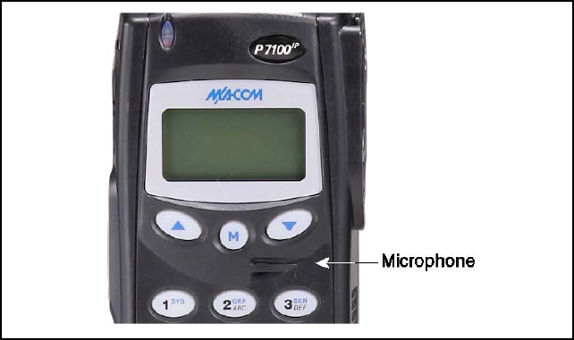
OPERATION FOLLOWING WATER CONTACT
If the P7100IP model radio has been immersed in water or if the microphone
air path or speaker grill become clogged with water, follow instructions under
“Radio Microphone” and “Radio Speaker” sections to assure the highest
quality transmitted and received messages.
RADIO MICROPHONE
In the event the P7100IP microphone air path becomes clogged with water,
blow two quick successive breaths of air directly into the radio microphone air
hole. Refer to Figure 18. This will help to clear any water trapped in the
microphone air path and allow the microphone to function properly.
Figure 18: Radio Microphone
RADIO SPEAKER
To assure the user receives the highest quality receive audio possible after the
radio has contacted water or been immersed, it may be necessary to clear
excess water from the speaker cavity and grill. The speaker grill has been
designed for easy drainage. To facilitate maximum drainage and the highest
quality speaker output, shake the radio vigorously with speaker grill face
down.
59
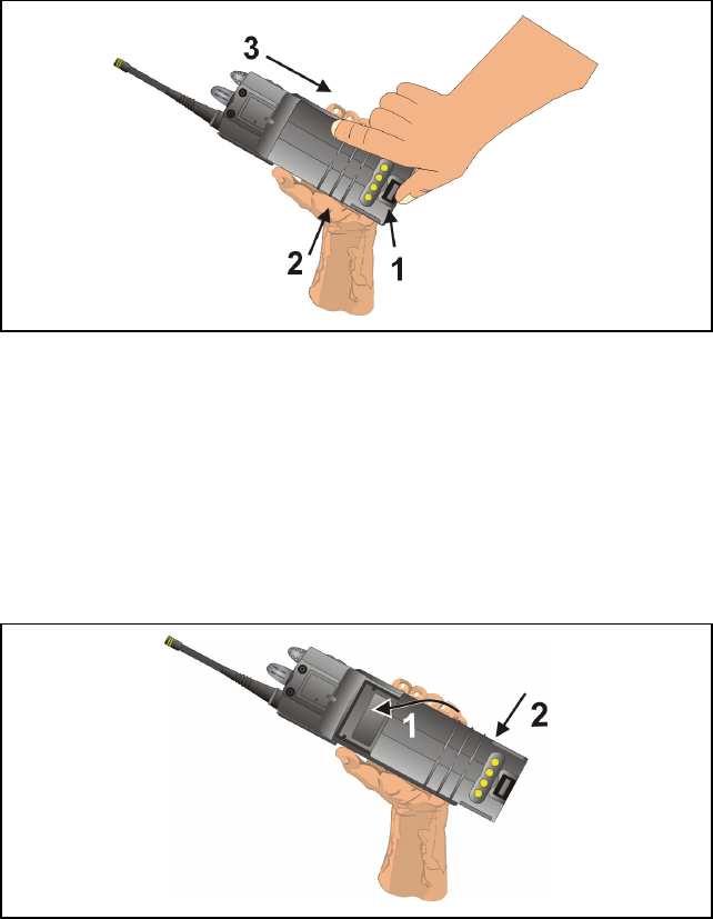
CHANGING THE BATTERY PACK
REMOVING THE BATTERY PACK
Make sure the power to the radio is turned OFF.
1. Press the latch at the bottom of the battery pack.
2. Lift the battery pack from the bottom.
3. Remove the battery pack from the radio.
Figure 19: Removing the Battery Pack
ATTACHING THE BATTERY PACK
Make sure the power to the radio is turned OFF.
1. Align the tab on the top of the battery pack with the slot at the top of the
battery cavity.
2. Push the battery pack down to attach the battery to the radio.
3. Verify that the battery pack is properly latched to the radio.
Figure 20: Attaching the Battery Pack
60

61
BATTERY WARRANTY
A. M/A-COM, Inc. (hereinafter "Seller") warrants to the original purchaser for use (hereinafter "Buyer")
that nickel-cadmium and nickel-metal hydride batteries supplied by Seller shall be free from defects
in material and workmanship, and shall conform to its published specifications for a period of
twelve (12) months from the date of purchase.
B. For purposes of this warranty, batteries shall be deemed defective if (1) the battery capacity is less
than 80% rated capacity, or (2) the battery develops leakage.
C. If any battery fails to meet the foregoing warranty, Seller shall correct the failure by issuing a
replacement battery upon receipt of the defective battery at an Authorized Service Center (ASC) or
M/A-COM factory (for OpenSky® Equipment only).
D. Replacement batteries shall be warranted only for the remaining unexpired warranty period of the
original battery. This warranty becomes void if:
1. The battery has been subjected to any kind of misuse, detrimental exposure, or has been
involved in an accident.
2. The battery is used in equipment or service other than the radio equipment for which it is
specified.
E. The preceding paragraphs set forth the exclusive remedies for claims based upon defects in or
non-conformity of any battery, whether the claim is in contract, warranty, tort (including
negligence), strict liability or otherwise, and however instituted. Upon the expiration of the warranty
period, all such liability shall terminate. The foregoing warranties are exclusive and in lieu of all
other warranties, whether oral, written, expressed, implied or statutory. NO IMPLIED OR
STATUTORY WARRANTIES OF MERCHANTABILITY OR FITNESS FOR PARTICULAR
PURPOSE SHALL APPLY. IN NO EVENT SHALL THE COMPANY BE LIABLE FOR ANY
INCIDENTAL, CONSEQUENTIAL, SPECIAL, INDIRECT OR EXEMPLARY DAMAGES.
This warranty applies only within the United States.
M/A-COM, Inc. M/A-COM, Inc.
1011 Pawtucket Blvd. 221 Jefferson Ridge Parkway
Lowell, MA 01853 Lynchburg, VA 24501
1-877-OPENSKY 1-800-528-7711
ECR-7048B

62
WARRANTY
A. M/A-COM, Inc. (hereinafter "Seller") warrants to the original purchaser for use (hereinafter "Buyer")
that Equipment manufactured by or for the Seller shall be free from defects in material and
workmanship, and shall conform to its published specifications. With respect to all non-M/A-COM
Equipment, Seller gives no warranty, and only the warranty, if any, given by the manufacturer shall
apply. Rechargeable batteries are excluded from this warranty but are warranted under a separate
Rechargeable Battery Warranty (ECR-7048).
B. Seller’s obligations set forth in Paragraph C below shall apply only to failures to meet the above
warranties occurring within the following periods of time from date of sale to the Buyer and are
conditioned on Buyer’s giving written notice to Seller within thirty (30) days of such occurrence:
1. for fuses and non-rechargeable batteries, operable on arrival only.
2. for parts and accessories (except as noted in B.1) sold by Seller’s Service Parts Operation,
ninety (90) days.
3. for PANTHER™ Series handportable and mobile radios, two (2) years.
4. for all other equipment of Seller’s manufacture, one (1) year.
C. If any Equipment fails to meet the foregoing warranties, Seller shall correct the failure at its option
(i) by repairing any defective or damaged part or parts thereof, (ii) by making available at Seller’s
factory any necessary repaired or replacement parts, or (iii) by replacing the failed Equipment with
equivalent new or refurbished Equipment. Any repaired or replacement part furnished hereunder
shall be warranted for the remainder of the warranty period of the Equipment in which it is installed.
Where such failure cannot be corrected by Seller’s reasonable efforts, the parties will negotiate an
equitable adjustment in price. Labor to perform warranty service will be provided at no charge
during the warranty period only for the Equipment covered under Paragraph B.3 and B.4. To be
eligible for no-charge labor, service must be performed at a M/A-COM factory, by an Authorized
Service Center (ASC) or other Servicer approved for these purposes either at its place of business
during normal business hours, for mobile or personal equipment, or at the Buyer’s location, for
fixed location equipment. Service on fixed location equipment more than thirty (30) miles from the
Service Center or other approved Servicer’s place of business will include a charge for
transportation.
D. Seller’s obligations under Paragraph C shall not apply to any Equipment, or part thereof, which (i)
has been modified or otherwise altered other than pursuant to Seller’s written instructions or written
approval or, (ii) is normally consumed in operation or, (iii) has a normal life inherently shorter than
the warranty periods specified in Paragraph B, or (iv) is not properly stored, installed, used,
maintained or repaired, or, (v) has been subjected to any other kind of misuse or detrimental
exposure, or has been involved in an accident.
E. The preceding paragraphs set forth the exclusive remedies for claims based upon defects in or
nonconformity of the Equipment, whether the claim is in contract, warranty, tort (including
negligence), strict liability or otherwise, and however instituted. Upon the expiration of the warranty
period, all such liability shall terminate. The foregoing warranties are exclusive and in lieu of all
other warranties, whether oral, written, expressed, implied or statutory. NO IMPLIED OR
STATUTORY WARRANTIES OF MERCHANTABILITY OR FITNESS FOR PARTICULAR
PURPOSE SHALL APPLY. IN NO EVENT SHALL THE SELLER BE LIABLE FOR ANY
INCIDENTAL, CONSEQUENTIAL, SPECIAL, INDIRECT OR EXEMPLARY DAMAGES.
This warranty applies only within the United States.
M/A-COM, Inc. M/A-COM, Inc.
1011 Pawtucket Blvd. 221 Jefferson Ridge Parkway
Lowell, MA 01853 Lynchburg, VA 24501
1-877-OPENSKY 1-800-528-7711
ECR-7047C

63
M/A-COM Technical Publications would particularly appreciate feedback on any errors found in
this document and suggestions on how the document could be improved. Submit your comments
and suggestions to:
Wireless Systems Business Unit
M/A-COM, Inc.
Technical Publications
221 Jefferson Ridge Parkway
Lynchburg, VA 24501
or
fax your comments to: (434) 455-6851
or
e-mail us at: techpubs@tycoelectronics.com
NOTES

M/A-COM Wireless Systems
221 Jefferson Ridge Parkway
Lynchburg, Virginia 24501
(Outside USA, 434-385-2400) Toll Free 800-528-7711
www.macom-wireless.com Printed in U.S.A.