HARRIS TR-0025-E Land Mobile Base Station User Manual Manual 2
HARRIS CORPORATION Land Mobile Base Station Manual 2
HARRIS >
Contents
- 1. Manual 1
- 2. Manual 2
- 3. Manual 3
- 4. Manual 4
Manual 2

Maintenance Manual
LBI-38812K
EDACS Interface Panels
19D904009G1-G32
TABLE OF CONTENTS
EDACS Interface Module...................................... LBI-38813
PTT Module............................................................. LBI-38816
EDACS CTIS Module ........................................... LBI-38818
Power Monitor for Simulcast ................................... LBI-38819
EDACS Interface VAX Site Controller ................. LBI-38943
Power Monitor / Channel Select Module................. LBI-38944
Simulcast 150 Baud Interface Module..................... LBI-38945
Euro EDACS Interface Board................................ LBI-38946
RIC Transformer Signal In/Out Isolation................. LBI-38947
EDACS Interface TUAI for Simulcast................... LBI-38948
STN-Voter Interface Board...................................... LBI-39021
RIC-Voter Interface Board....................................... LBI-39022
Timing Interface Module ......................................... LBI-39099
Serial Interface Module............................................ LBI-39136
Power Sensor Interface Module............................... LBI-39137
Site Sentry/ELI/SIM Interface Board........ EN/LZB 119 3775/1
Prism ELI Audio Interface Module........... AE/LZB 119 4106/1

2LBI-38812K
MANUAL REVISION
LBI-38812J – Added EDACS Interface Panels 19C904009G31 and G32 used in SitePro applications. Updated
parts list and all drawings to the latest revision (Revision 5). Reformatted manual for M/A-COM
Private Radio Systems, Inc.
LBI-38812K – Added revised drawing, 19D904009 ( Revision 7), and safety information
SAFETY NOTICE
• The means of disconnecting power from a station cabinet is the cabinet power supply plug.
• When conducting repair/maintenance, disconnect the cabinet power supply plug from the AC source.
• In European applications, equipment must be installed in a closed cabinet.
• Only replace components with components specified by M/A-COM Private Radio Systems, Inc.
NOTICE!
This manual covers M/A-COM Private Radio Systems, Inc., products manufactured and sold by M/A-COM Private
Radio Systems, Inc.
NOTICE!
Repairs to this equipment should be made only by an authorized service technician or facility designated by the supplier. Any
repairs, alterations or substitution of recommended parts made by the user to this equipment not approved by the
manufacturer could void the user’s authority to operate the equipment in addition to the manufacturer’s warranty.
NOTICE!
The software contained in this device is copyrighted by M/A-COM Private Radio Systems, Inc. Unpublished rights are
reserved under the copyright laws of the United States.
This manual is published by M/A-COM Private Radio Systems, Inc., without any warranty. Improvements and changes to this manual necessitated by
typographical errors, inaccuracies of current information, or improvements to programs and/or equipment, may be made by M/A-COM Private Radio
Systems, Inc., at any time and without notice. Such changes will be incorporated into new editions of this manual. No part of this manual may be
reproduced or transmitted in any form or by any means, electronic or mechanical, including photocopying and recording, for any purpose, without the
express written permission of M/A-COM Private Radio Systems, Inc.
Copyright © 1994-2002 M/A-COM Private Radio Systems, Inc. All rights reserved.

TABLE OF CONTENTS
LBI-38812K 3
TABLE OF CONTENTS
Page
1.0 SPECIFICATIONS ................................................................................................................................................4
2.0 PANEL DESCRIPTIONS ...................................................................................................................................... 5
3.0 MODULE DESCRIPTIONS.................................................................................................................................. 9
4.0 PARTS LIST........................................................................................................................................................ 11
5.0 STATION ASSEMBLY DIAGRAMS:................................................................................................................12
EDACS INTERFACE PANEL (G1) – STATION ASSEMBLY .....................................................................12
EDACS INTERFACE PANEL (G2) - CTIS MAIN COMPUTER CABINET ................................................ 13
EDACS INTERFACE PANEL (G3) – CTIS RIC CABINET.......................................................................... 14
EDACS INTERFACE PANEL (G4) – SIMULCAST STATION....................................................................15
EDACS INTERFACE PANEL (G5) – SIMULCAST TX COMMON EQUIPMENT ....................................16
EDACS INTERFACE PANEL (G6) – SITE CONTROLLER-PDP11 ............................................................17
EDACS INTERFACE PANEL (G7) – AUXILIARY RECEIVER – MODEM...............................................18
EDACS INTERFACE PANEL (G8) – EURO EDACS ASSEMBLY ............................................................. 19
EDACS INTERFACE PANEL (G9) – GETC SIMULCAST CONTROL POINT (1-12) ...............................20
EDACS INTERFACE PANEL (G10) – GETC SIMULCAST CONTROL POINT (13-20) ...........................21
EDACS INTERFACE PANEL (G11) – VOTER INTERFACE PANEL ........................................................ 22
EDACS INTERFACE PANEL (G12) – SITE CONTROLLER VAX-DEC (#1) ............................................ 23
EDACS INTERFACE PANEL (G13) – SITE CONTROLLER VAX-DEC (#2) ............................................ 24
EDACS INTERFACE PANEL (G14) – CTIS MAIN COMPUTER VAX-DEC............................................. 25
EDACS INTERFACE PANEL (G15) – SIMULCAST CONTROL POINT ...................................................26
EDACS INTERFACE PANEL (G16) – EURO EDACS LEASED LINE INTERFACE................................. 27
EDACS INTERFACE PANEL (G17) – RIC TRANSFORMER PANEL........................................................28
EDACS INTERFACE PANEL (G18) – JESSICA CONTROL .......................................................................29
EDACS INTERFACE PANEL (G19) – DVIU INTERFACE PANEL............................................................30
EDACS INTERFACE PANEL (G20) – STN VOTER INTERFACE.............................................................. 31
EDACS INTERFACE PANEL (G21) – VOTER RIC INTERFACE...............................................................32
EDACS INTERFACE PANEL (G22) – AUXILIARY RECEIVER RS-232...................................................33
EDACS INTERFACE PANEL (G23) – AUXILIARY RECEIVER C0ONVENTIONAL..............................34
EDACS INTERFACE PANEL (G25) – SIMULCAST TX STE (RS-232 DATA).......................................... 35
EDACS INTERFACE PANEL (G26) – SIM INTERFACE PANEL...............................................................36
EDACS INTERFACE PANEL (G28) – SITE SENTRY/ELI/SIM (MASTR III)............................................ 37
EDACS INTERFACE PANEL (G29) – PRISM SITE SENTRY/SIM ............................................................38
EDACS INTERFACE PANEL (G30) – PRISM ELI AUDIO .........................................................................39
EDACS INTERFACE PANEL (G31 & G32) – STATION ASSEMBLY WITH SITEPRO...........................40

SPECIFICATIONS
4LBI-38812K
1.0 SPECIFICATIONS1
DIMENSIONS...........................19” wide X 5 1/4” high (3 RU)
MOUNTING..............................Fits standard 19-inch equipment rack.
MODULES ................................Provides mounting space for one 1 7/8” wide X 5 1/8”
high module, and up to five 3” wide X 5 1/8” high
modules. (Spaces may also be combined to
accommodate wider modules.)
1 These specifications are intended primarily for the use of the service technician. Refer to the appropriate Specifications
Sheet in the applicable maintenance manual for the complete specifications.

PANEL DESCRIPTIONS
LBI-38812K 5
2.0 PANEL DESCRIPTIONS
The 19D904009G1 through G30 (group 1 through group 30) Enhanced Digital Access
Communications System (EDACS) Interface Panels are used as the connection points
between cables outside and cables inside an EDACS equipment cabinet. The EDACS
Interface Panels are intended to simplify the wiring between EDACS equipment cabinets
through the use of standard cables and easily accessible connection points.
Each EDACS Interface Panel consists of a frame on which one or more interface
modules are mounted. Each EDACS Interface Panel group number, representing one
combination of these interface modules, is described below. The Assembly Diagrams
located at the end of this manual, show where and which interface modules are mounted
on the frame.
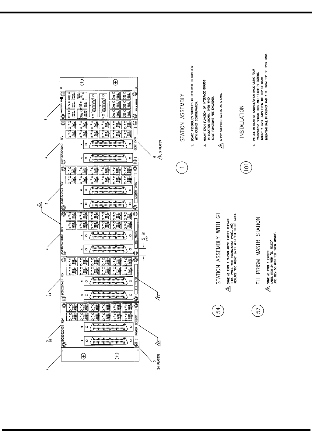
19D904009G1 Station Assembly - This interface panel provides the connection points
for the standard EDACS Repeater cabinet to accommodate the IDA Local Telephone
Interconnect. See Assembly Diagram 19D904009, Sheet 1, Part 1 (number in circle).
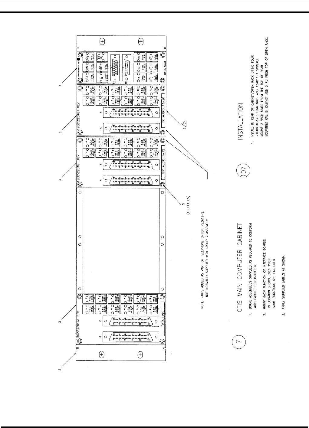
19D904009G2 CTIS Main Computer Cabinet - This interface panel provides the
connection points for the CTIS Main Computer cabinet to accommodate the PDP
computer. See Assembly Diagram 19D904009, Sheet 2, Part 7 (number in circle).
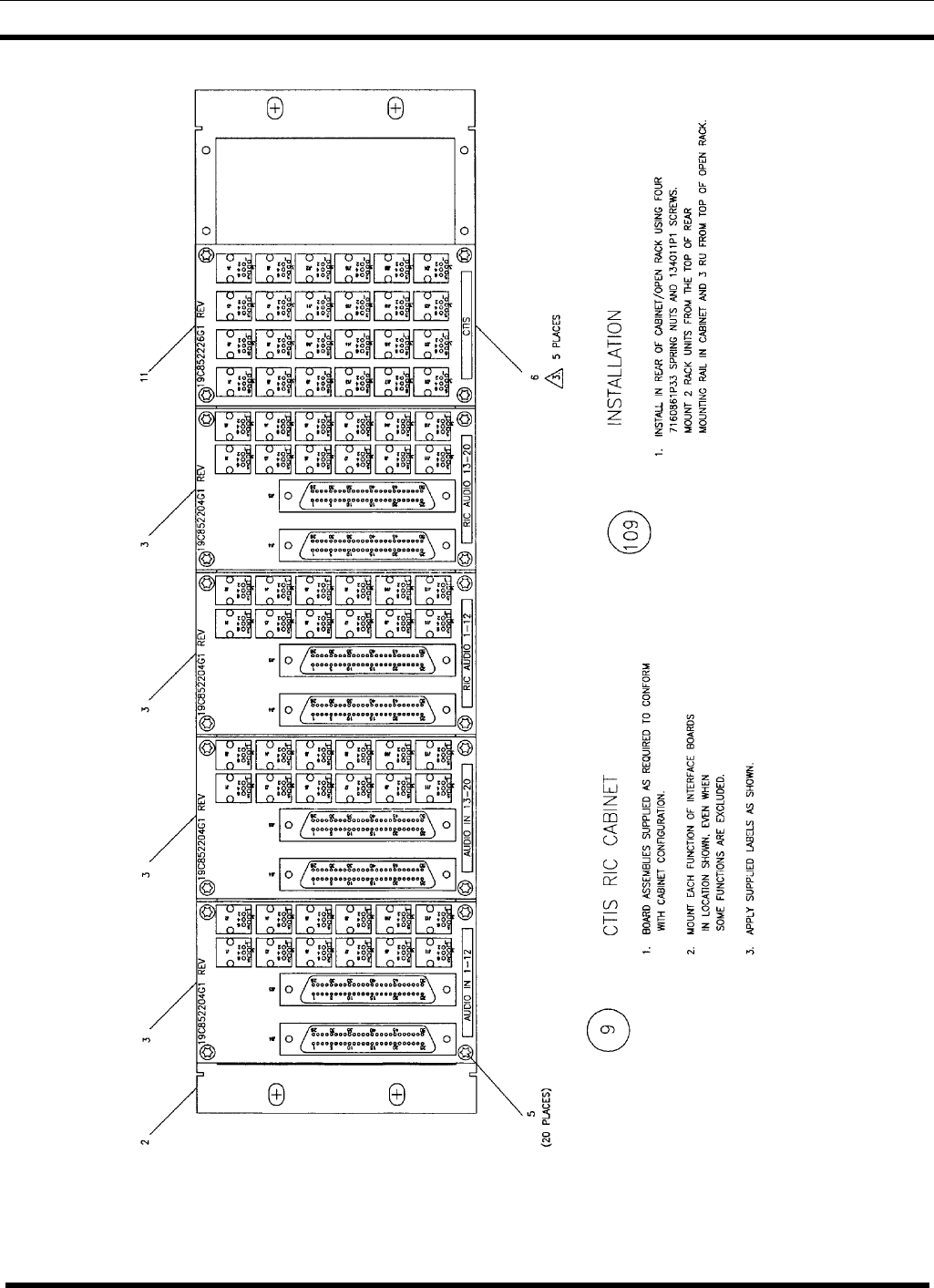
19D904009G3 CTIS RIC Cabinet - This interface panel provides the connection points
for the cabinet containing the CTIS RIC’s. See Assembly Diagram 19D904009, Sheet 3,
Part 9 (number in circle).
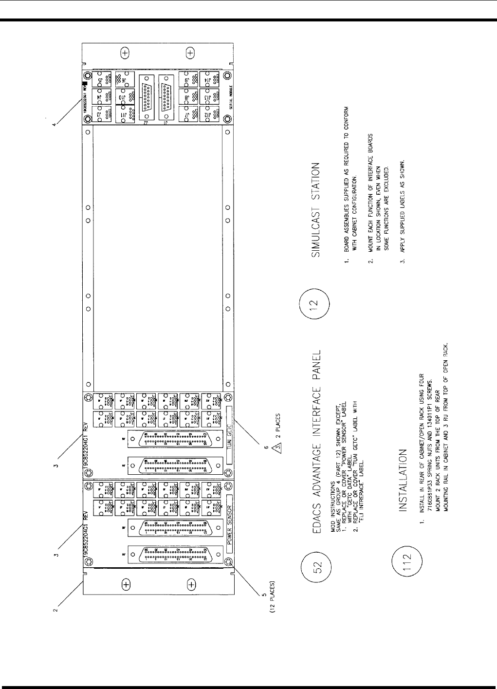
19D904009G4 Simulcast Station - This interface panel provides the connection points
for the Simulcast Station cabinet. See Assembly Diagram 19D904009, Sheet 4, Part 12
(number in circle).
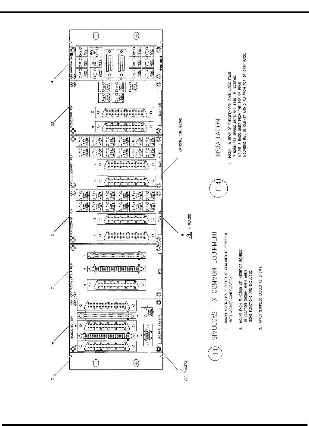
19D904009G5 Simulcast Tx Common Equipment - This interface panel provides the
connection points for the cabinet containing the common equipment at a Simulcast
transmit site. See Assembly Diagram 19D904009, Sheet 5, Part 14 (number in circle).
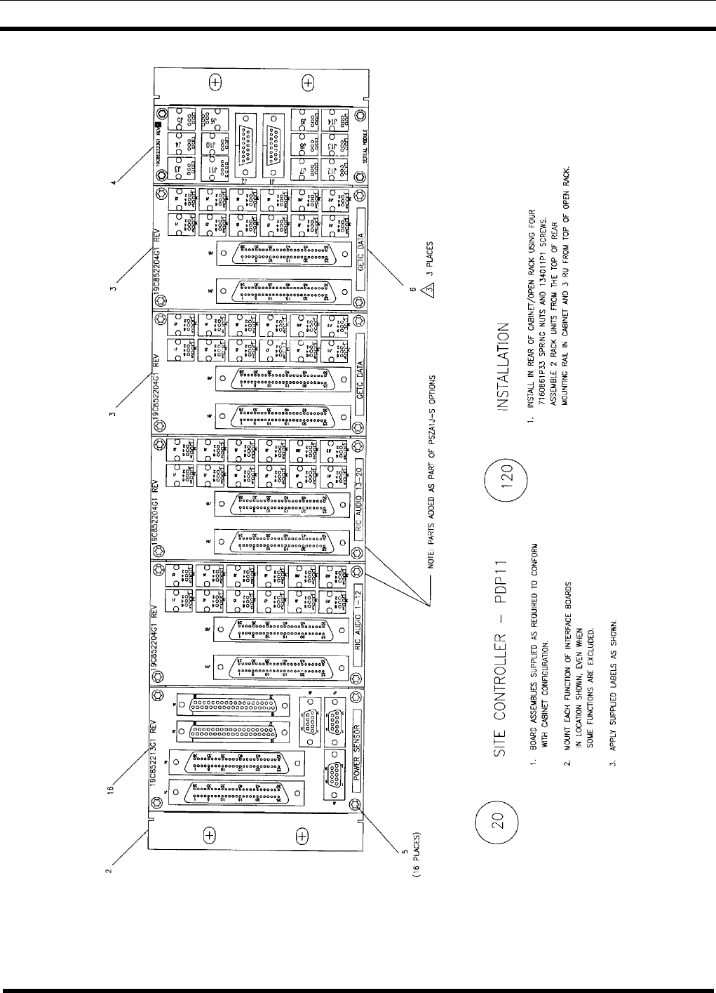
19D904009G6 Site Controller - PDP11 - This interface panel provides the connection
points for the Site Controller cabinet to accommodate the PDP computer. See Assembly
Diagram 19D904009, Sheet 6, Part 20 (number in circle).
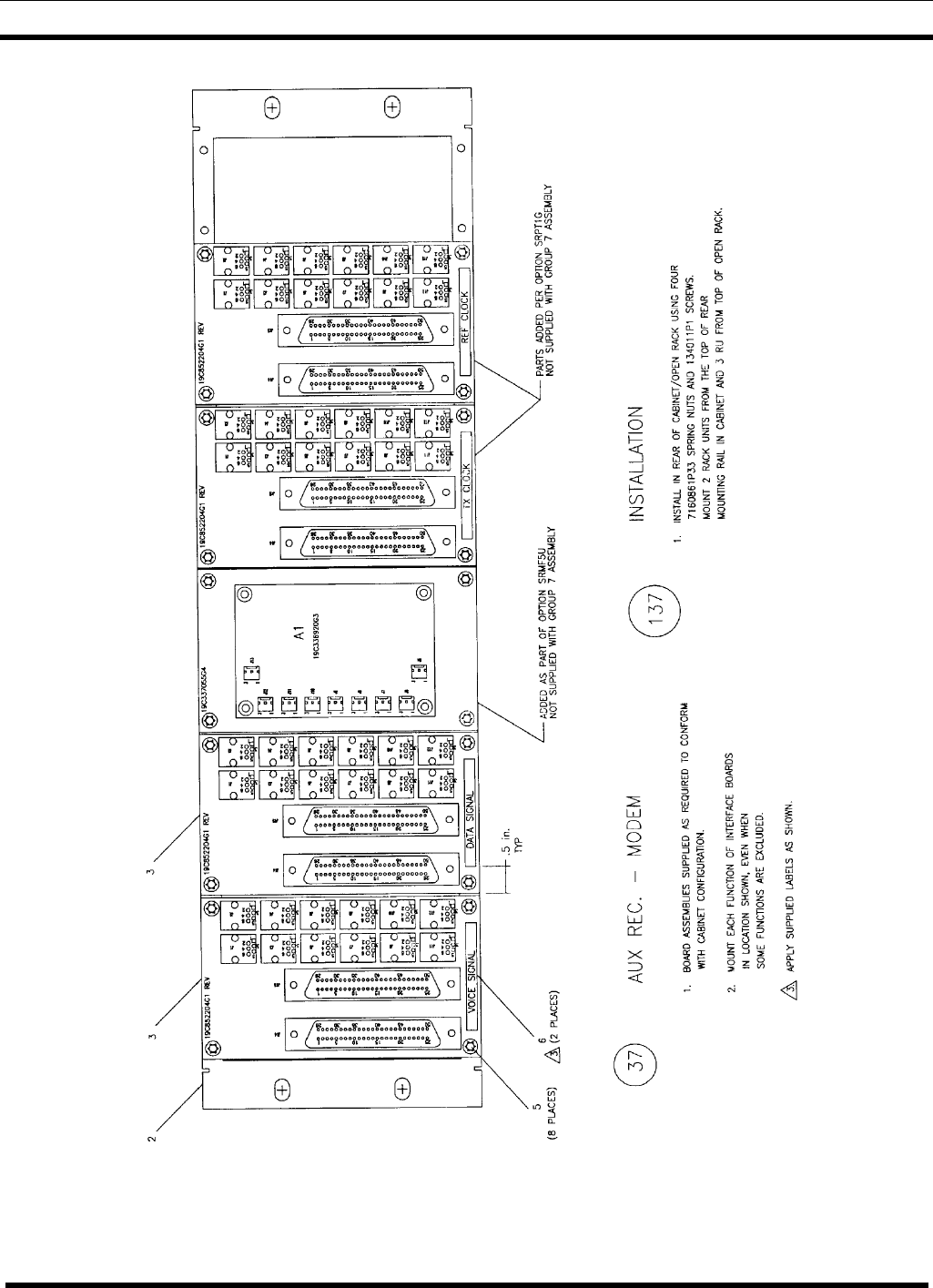
19D904009G7 Auxiliary Receiver - Modem - This interface panel provides the
connection points for voice and data circuits to a cabinet containing Auxiliary Receivers.
See Assembly Diagram 19D904009, Sheet 7, Part 37 (number in circle).
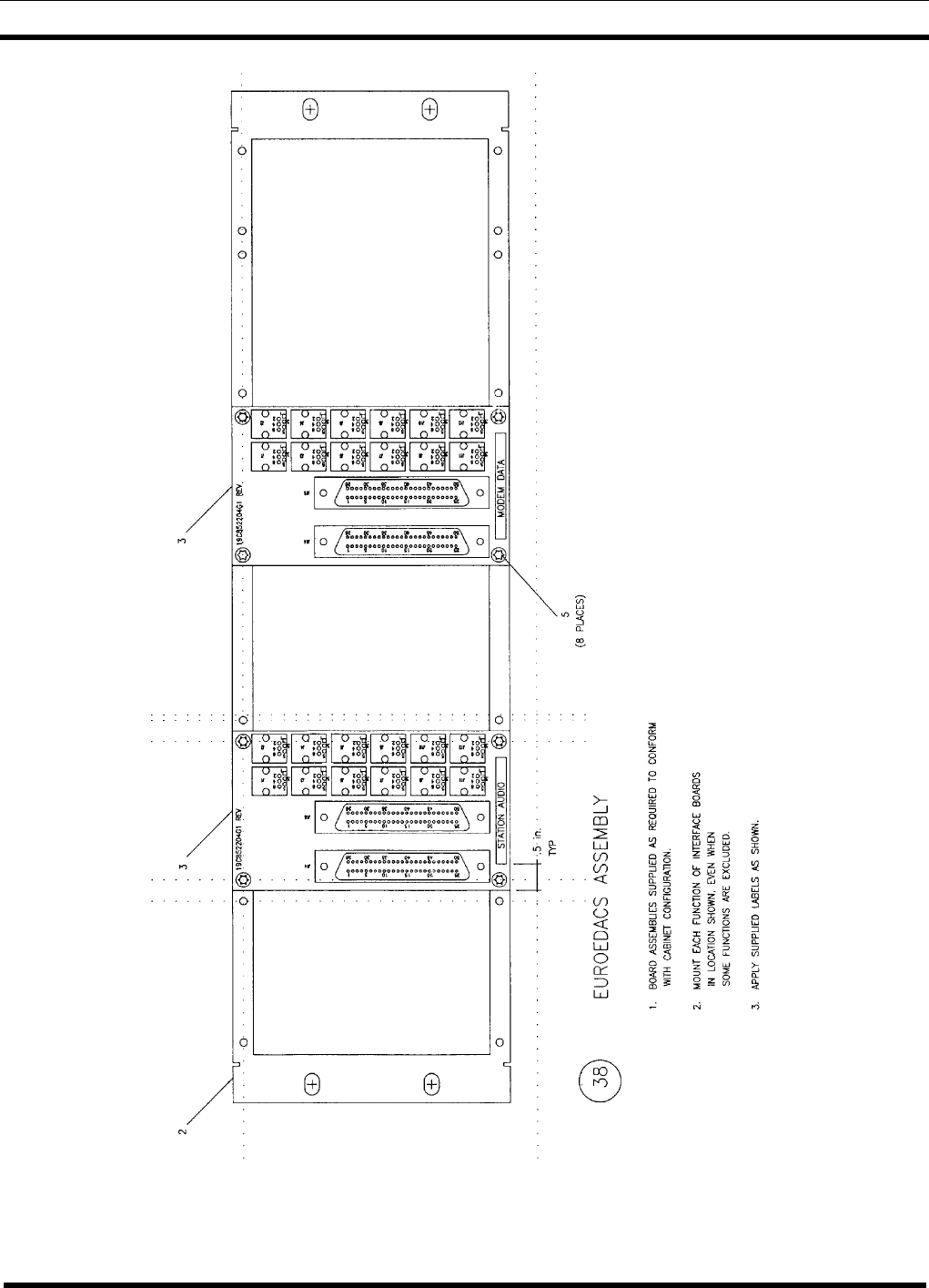
19D904009G8 Euro EDACS Assembly - This interface panel provides the connection
points for station audio and modem data circuits in some European EDACS applications.
See Assembly Diagram 19D904009, Sheet 8, Part 38 (number in circle).
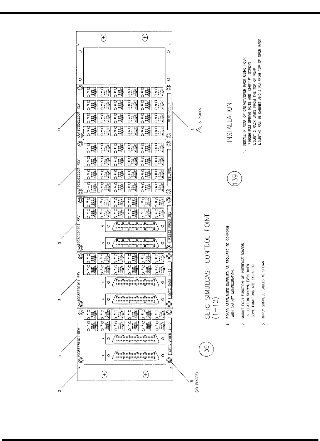
19D904009G9 GETC Simulcast Control Point (1-12) - This interface panel provides
the connection points for the cabinet containing the GETC’s for channels 1 through 12 at
the Control Point location in a Simulcast System. See Assembly Diagram 19D904009,
Sheet 9, Part 39 (number in circle).
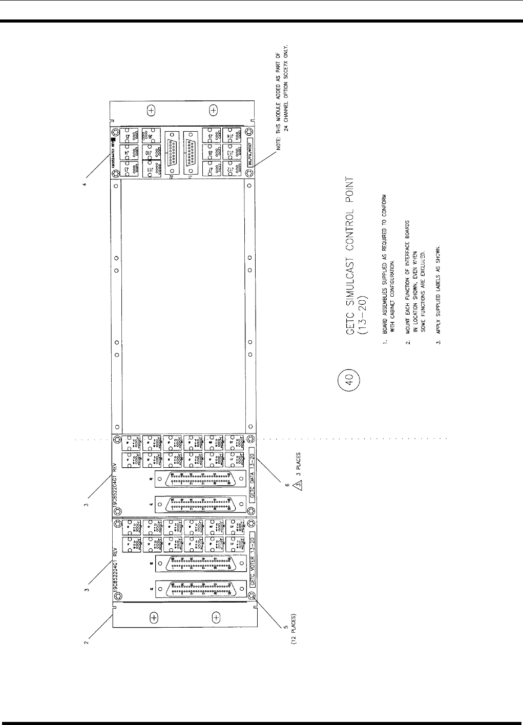
19D904009G10 GETC Simulcast Control Point (13-20) - This interface panel
provides the connection points for the cabinet containing the GETC’s for channels 13
through 20 at the Control Point location in a Simulcast System. See Assembly Diagram
19D904009, Sheet 10, Part 40 (number in circle).

SPECIFICATIONS
6LBI-38812K
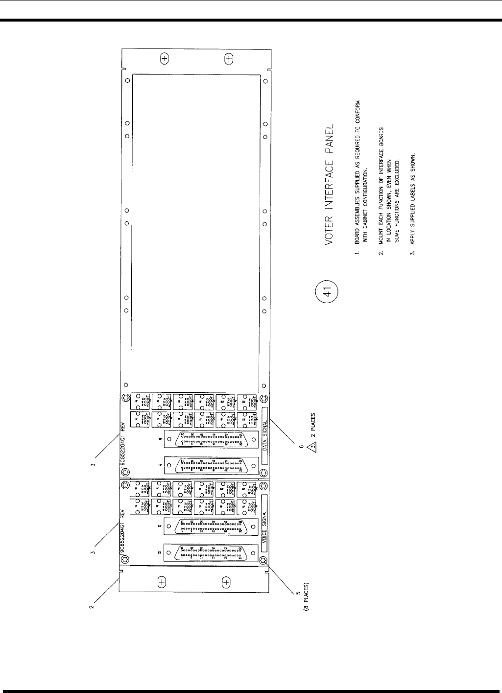
19D904009G11 Voter Interface Panel - This interface panel provides the connection
points for the cabinet containing the Voter at the Main location in a Voted System or at
the Control Point location in a Simulcast System. See Assembly Diagram 19D904009,
Sheet 11, Part 41 (number in circle).
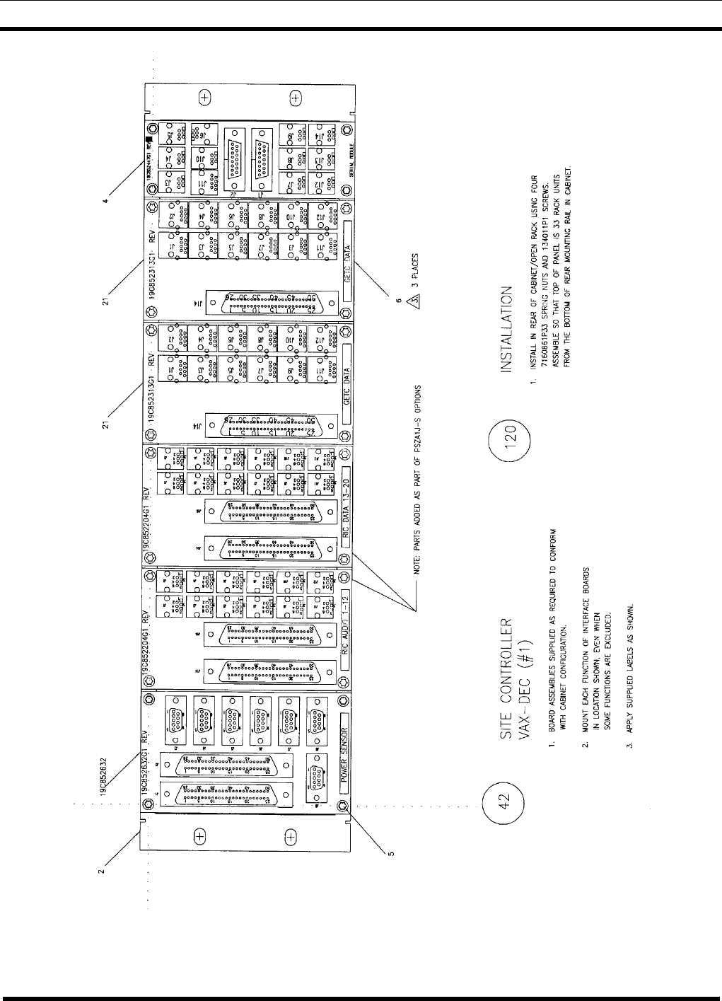
19D904009G12 Site Controller VAX-DEC (#1) - This interface panel (along with G13)
provides the connection points for the Site Controller cabinet to accommodate the VAX
computer. See Assembly Diagram 19D904009, Sheet 12, Part 42 (number in circle).
19D904009G13 Site Controller VAX-DEC (#2) - This interface panel (along with G12)
provides the connection points for the Site Controller cabinet to accommodate the VAX
computer. See Assembly Diagram 19D904009, Sheet 13, Part 43 (number in circle).
19D904009G14 CTIS Main Computer VAX-DEC - This interface panel replaces the
G2 CTIS Main Computer Cabinet Panel, to accommodate a VAX computer, and
provides the connection points for the latest CTIS Main Computer cabinet. See
Assembly Diagram 19D904009, Sheet 14, Part 44 (number in circle).
19D904009G15 Simulcast Control Point - This interface panel is used to re-map
jackfield appearances of 150-Baud data at the Control Point location in a Simulcast
System. See Assembly Diagram 19D904009, Sheet 15, Part 45 (number in circle).
19D904009G16 Euro EDACS Lease Line Interface - This interface panel provides
connection points for some European EDACS applications requiring 8-pin modular RJ11
type connectors. See Assembly Diagram 19D904009, Sheet 16, Part 46 (number in
circle).
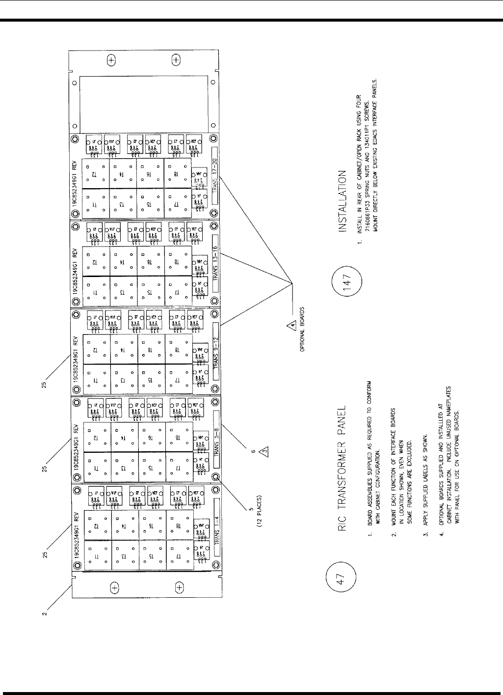
19D904009G17 RIC Transformer Panel - This interface panel provides connection
points and isolation transformers for the RIC audio circuits to the cabinet containing the
RIC Shelves at a CTIS site, or the Control Point location in a Simulcast System. See
Assembly Diagram 19D904009, Sheet 17, Part 47 (number in circle).
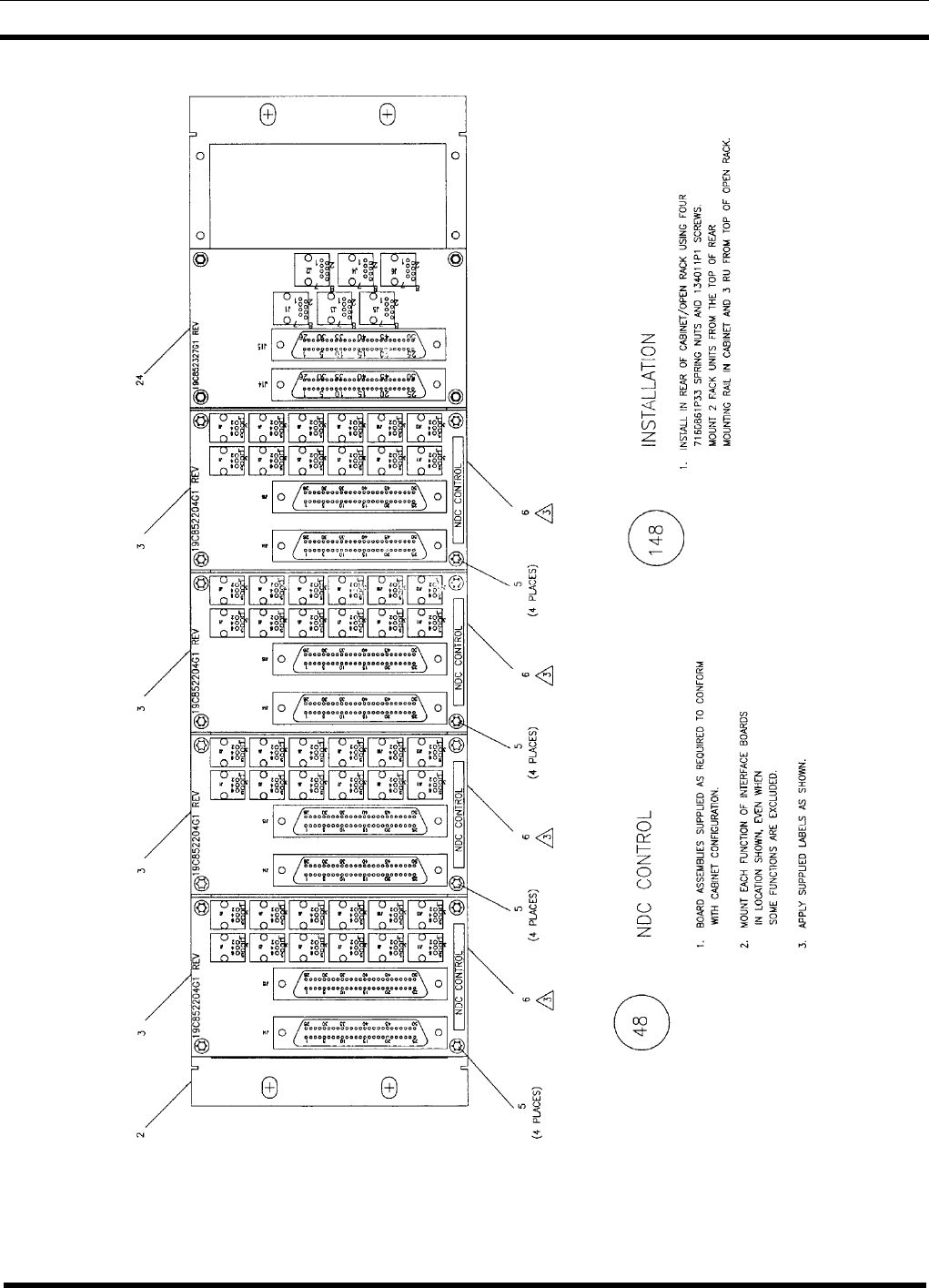
19D904009G18 Jessica Control - This interface panel provides connection points for
the EDACS Data Gateway cabinet in the Jessica centralized telephone interconnect
system. See Assembly Diagram 19D904009, Sheet 18, Part 48 (number in circle).
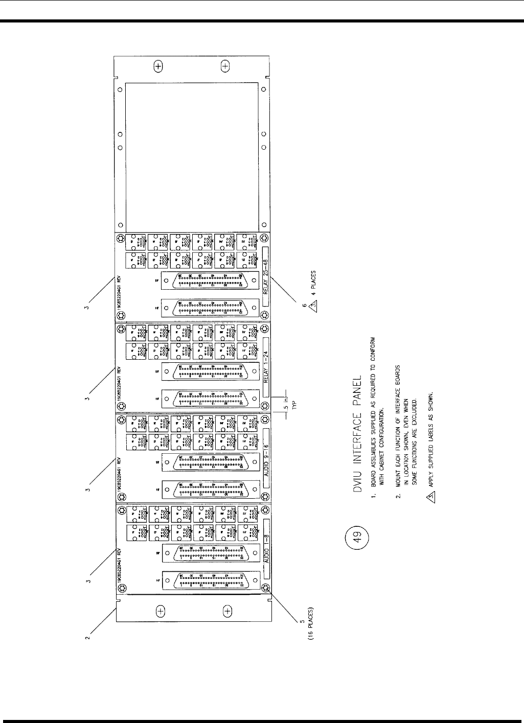
19D904009G19 DVIU Interface Panel - This interface panel provides connection
points for the Console Interface Unit. See Assembly Diagram 19D904009, Sheet 19, Part
49 (number in circle).
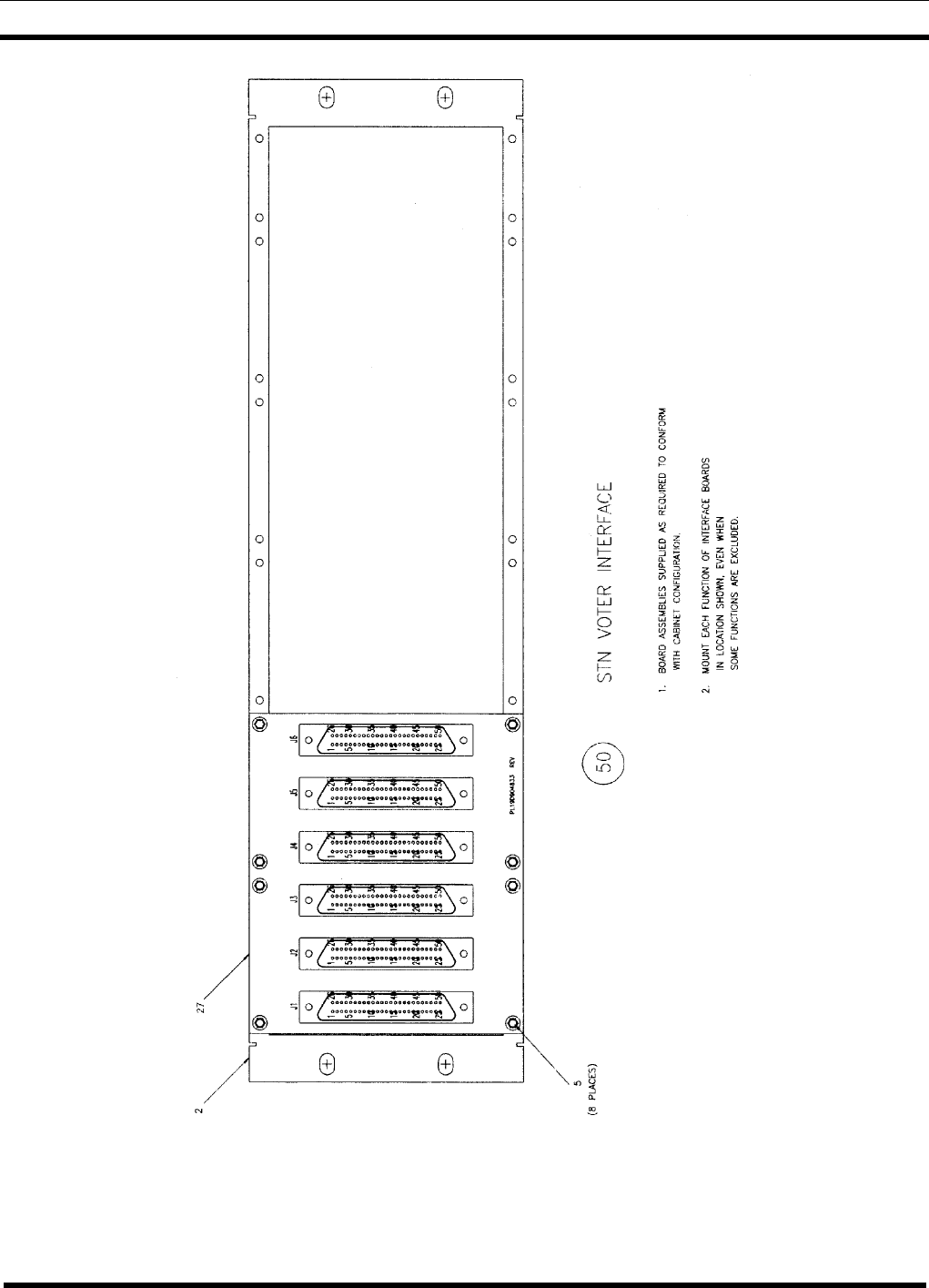
19D904009G20 STN Voter Interface - This interface panel provides the connection
points between modem shelves and the IMC switch (or the Voter Selector GETC) for a
Simulcast System. See Assembly Diagram 19D904009, Sheet 20, Part 50 (number in
circle).
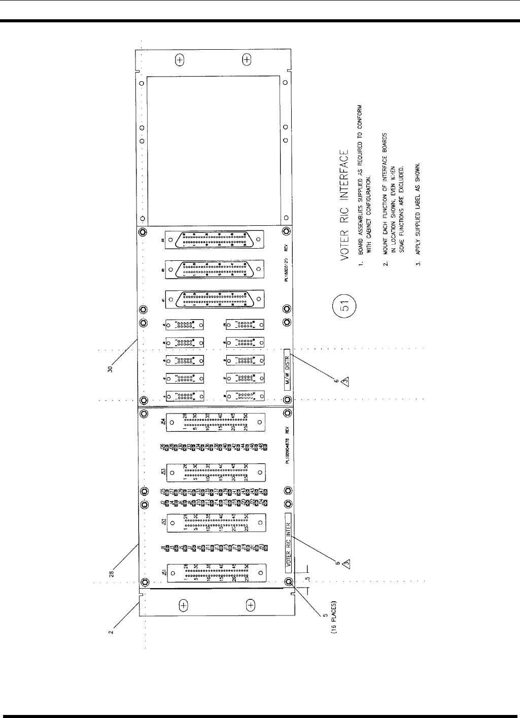
19D904009G21 Voter RIC Interface - This interface panel provides connection points
at the Control Point location in a Simulcast System. See Assembly Diagram 19D904009,
Sheet 21, Part 51 (number in circle).
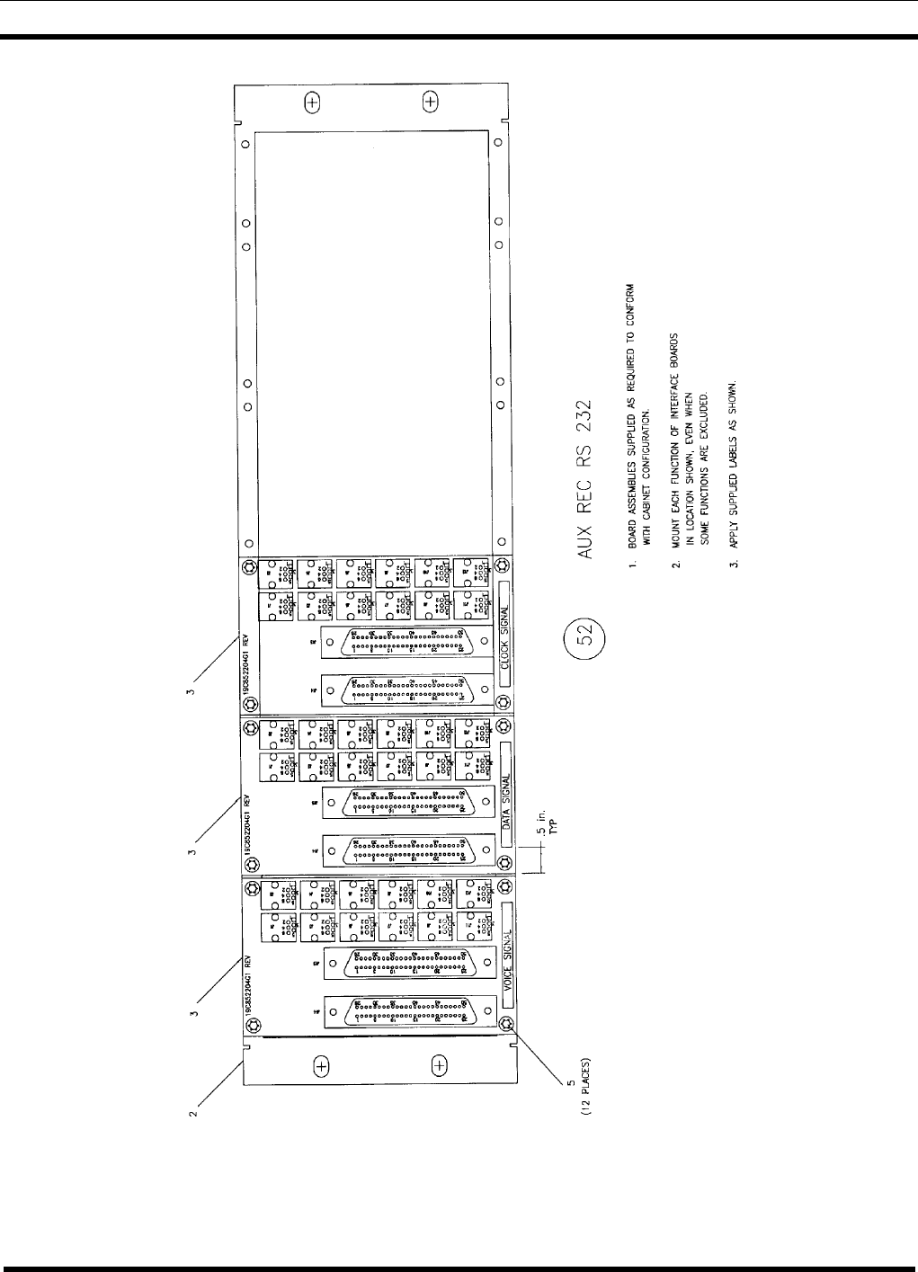
19D904009G22 Auxiliary Receiver RS-232 - This interface panel provides the
connection points for a cabinet containing trunked MASTR III Auxiliary Receivers. See
Assembly Diagram 19D904009, Sheet 22, Part 52 (number in circle).

PANEL DESCRIPTIONS
LBI-38812K 7
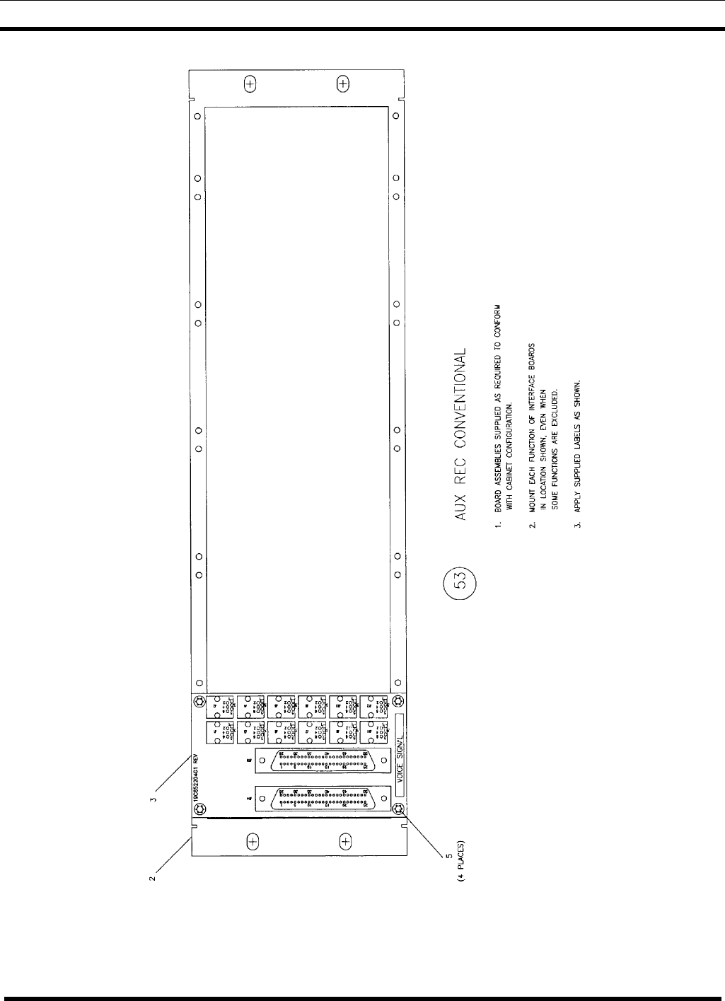
19D904009G23 Auxiliary Receiver Conventional - This interface panel provides the
connection points for a cabinet containing conventional MASTR III Auxiliary Receivers.
When this interface panel is used in the Voter 95 application, see LBI-39075. See
Assembly Diagram 19D904009, Sheet 23, Part 53 (number in circle).
19D904009G24 Station Assembly with GTI - This interface panel provides the
connection points for the standard EDACS Repeater cabinet to accommodate the ELI
Local Telephone Interconnect. See Assembly Diagram 19D904009, Sheet 1, Part 54
(number in circle).
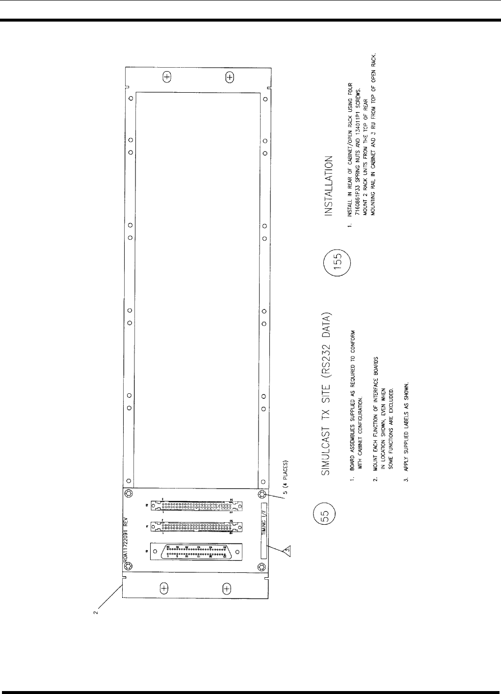
19D904009G25 Simulcast Tx Site (RS-232 Data) - This interface panel provides the
connection points for the channel clock signal circuits between the Channel Bank, the
Universal Sync. Shelf, and the Digital Cross Connect Panel (at the Control Point
location) or the Transmit Cross Connect Panel (at a Transmit Site) in a Simulcast
System. See Assembly Diagram 19D904009, Sheet 24, Part 55 (number in circle).
19D904009G26 – SIM Interface Panel - This interface panel provides the connection
points for the Site Interface Module (SIM) used in MASTR III station Hotline enhanced
telephone interconnect applications (Site Sentry & ELI). See Assembly Diagram
19D904009, Sheet 26, Part 60 (number in circle).
19D904009G27 – ELI/Site Controller Panel – This interface panel provides the
connection points for the Site Sentry module and Site Interface Module (SIM) used in
EDACS PRISM station Hotline enhanced telephone interconnect applications. See
Assembly Diagram 19D904009, Sheet 27, Part 61 (number in circle).
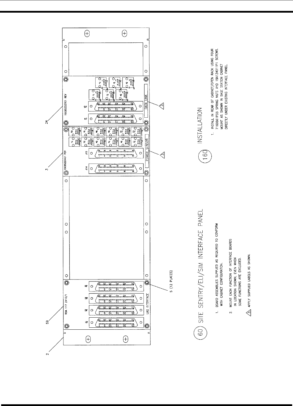
19D904009G28 SITE SENTRY/ELI/SIM (MASTR III) – This Interface Panel
provides the connections points in a MASTR III system for the power sensor circuits in
the system to the Site Sentry module. It also connects the Site Sentry module to the
Orion Test Unit module via the Site Interface module.
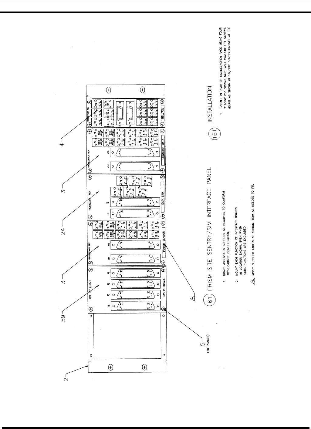
19D904009G29 PRISM SITE SENTRY/ELI/SIM – This Interface Panel provides the
connection points in a Prism MASTR system for the system to the Site Sentry module to
the Orion Test Unit module via the Site Interface module. Connections between the PM
BSL/FSL are made via the Serial Interface module to the SIM shelf.
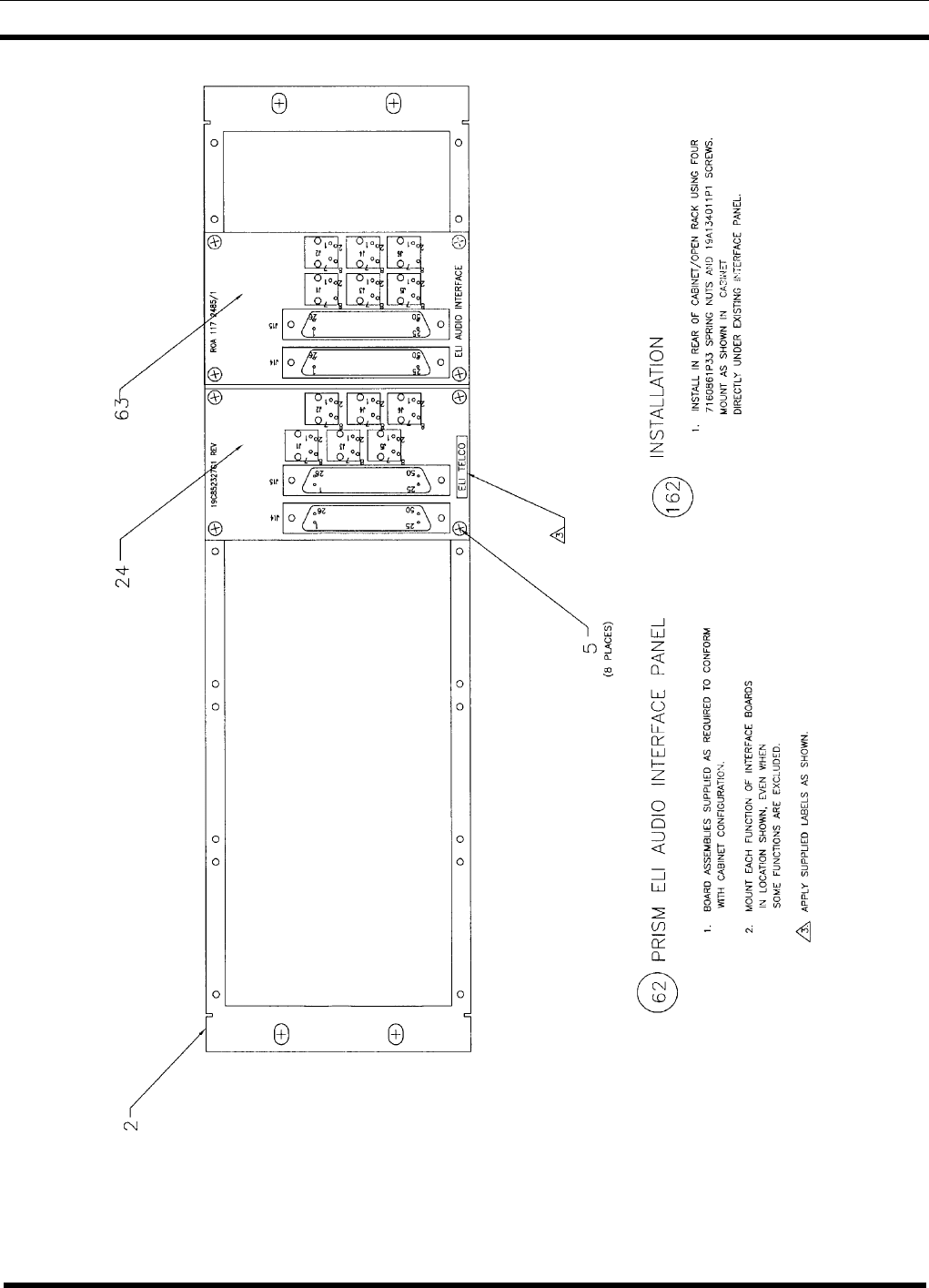
19D904009G30 PRISM ELI AUDIO – This Interface Panel provides the connection
points in a Prism MASTR system for the Tx audio and intercom audio from each channel
to its appropriate ELI shelf. It also connects the ELI shelf to the telephone lines.
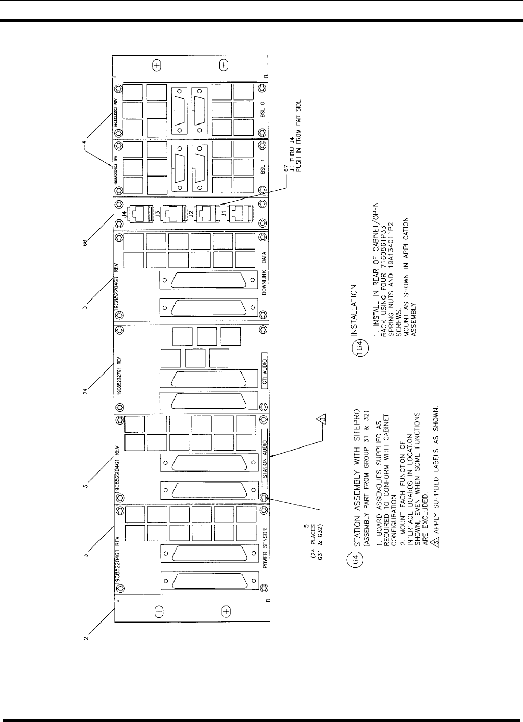
19D904009G31 STATION ASSEMBLY W/SITEPRO (Cabinet w/SIM) – This
interface panel provides the connection points for the standard EDACS repeater cabinet
w/SitePro. Connection points provided are BSL 0, BSL 1, Downlink Data, GTI Audio,
Station Audio and Power Sensor. See Assembly drawing 19D904009, Sheet 29, Part 64
(number in circle).
19D904009G32 STATION ASSEMBLY W/SITEPRO (Cabinet wo/SIM) – This
interface panel provides the connection points for the standard EDACS repeater cabinet
w/SitePro. Connection points provided are BSL 0, BSL1, Ethernet, GTI Audio, Station
Audio and Power Sensor. See Assembly drawing 19D904009, Sheet 29, Part 64 (number
in circle).
A summary of how many of which interface modules make up each EDACS Interface
Panel by group number is shown in Table 1.

PANEL DESCRIPTIONS
8LBI-38812K
Table 1 – Module Makeup of EDACS Interface Panels by Group Number
INTERFACE
MODULE 19D904009G1 THROUGH G32 EDACS INTERFACE PANEL
DRAWING NO. 1234567891011121314151617181920212223242526272829303132
19C852204G1 52421222222 34 2 44 314 1112 3 2
19C852213G1 1
19C852215G1 1
19C852218G1 1
19C852226G1 1 2
19C852313G1 2 1
19C852327G1 2 1 1 1 1 1 1 1 1 1
19C852339G1 1
19C852349G1 2
19C852447G1 1 1 1 1 1 1 1 1 1 1 2 2
19D904427G1 1
19D904678G1 1
19D904833G1 1
188D5120G1 1
ROA1172209 1
ROA1172410/1 11
ROA1172442/1 1
ROA1172485/1 1
FM101263V1 1
CN101314V1 4
Panel Names:
19D904009G1 - Station Assembly
19D904009G2 - CTIS Main Computer Cabinet
19D904009G3 - CTIS RIC Cabinet
19D904009G4 - Simulcast Station
19D904009G5 - Simulcast Tx Common Equipment
19D904009G6 - Site Controller - PDP11
19D904009G7 - Auxiliary Receiver - Modem
19D904009G8 - Euro EDACS Assembly
19D904009G9 - GETC Simulcast Control Point (1-12)
19D904009G10 - GETC Simulcast Control Point (13-20)
19D904009G11 - Voter Interface Panel
19D904009G12 - Site Controller VAX-DEC (#1)
19D904009G13 - Site Controller VAX-DEC (#2)
19D904009G14 - CTIS Main Computer VAX-DEC
19D904009G15 - Simulcast Control Point
19D904009G16 - Euro EDACS Lease Line Interface
19D904009G17 - RIC Transformer Panel
19D904009G18 - Jessica Control
19D904009G19 - DVIU Interface Panel
19D904009G20 - STN Voter Interface
19D904009G21 - Voter RIC Interface
19D904009G22 - Auxiliary Receiver RS-232
19D904009G23 - Auxiliary Receiver Conventional
19D904009G24 - Station Assembly with GTI
19D904009G25 - Simulcast Tx Site (RS-232 Data)
19D904009G26 – SIM Interface Panel
19D904009G27 – ELI/Site Controller Panel
19D904009G28 – UAS/ELI/SIM Panel (MASTR III)
19D904009G29 – Prism Site Sentry/ELI/SIM Panel
19D904009G30 – Prism ELI Audio Panel
19D904009G31 – Station Assembly w/SitePro
(cabinet w/SIM)
19D904009G32 – Station Assembly w/SitePro
(cabinet wo/SIM)
Module Names:
19C852204G1 - Interface Module
19C852213G1 - Power Monitor Module
19C852215G1 - PTT Module
19C852218G1 - Power Monitor Module for Simulcast
19C852226G1 - CTIS Module
19C852313G1 - VAX Site Controller
19C852327G1 - Euro EDACS Interface Board
19C852339G1 - TUAI for Simulcast
ROA1172442/1 - ELI Interface Module
ROA1172485/1 - Prism ELI Audio Module
19C852349G1 - RIC Transformer Signal In/Out Isolation
19C852447G1 - Serial Interface Module
19C852632G1 - Power Sensor Interface Module
19D904427G1 - Simulcast 150 Baud Interface Module
19D904678G1 - RIC-Voter Interface Board
19D904833G1 - STN-Voter Interface Board
188D5120G1 - Microwave Distribution Panel
ROA1172209 - Timing Interface Module
ROA1172410/1 - UAS/ELI/SIM Module (MASTR III)
ROA1172485/1 - Prism ELI Audio Module

MODULE DESCRIPTIONS
LBI-38812K 9
3.0 MODULE DESCRIPTIONS
The following descriptions for each interface module give the application and a reference
to the applicable instruction manual:
19C852204G1 Interface Module - This is a general-purpose interface module that
connects four wires from each of ten six-pin modular connectors (for inside connections)
to two fifty-pin Telco connectors (for outside connections). See LBI-38813.
19C852213G1 Power Monitor Module - This module provides the connection points
for transmitter and antenna power sensor circuits at the Site Controller cabinet when
using the old DB8843-based Power Monitor Unit. (See the 19C852632G1 Power Sensor
Interface Module when using the new DB8860-based Power Monitor Unit.) See LBI-
38815.
19C852215G1 PTT Module - This module is used as a connection point and cross
connect for the PTT and Analog/Digital signaling circuits between the microwave link
and the station transmitters at a Remote Transmit Site in a Simulcast system. See LBI-
38816.
19C852218G1 EDACS Interface Power Monitor Module for Simulcast - This
module provides the connection points for transmitter and antenna power sensor circuits
at a Simulcast site. See LBI-38819.
19C852226G1 EDACS CTIS Module - This module is used to collect and route
telephone interface analog/data for the Central Telephone Interconnect System (CTIS).
See LBI-38818.
19C852313G1 EDACS Interface VAX Site Controller - This module provides the
connection points for the GETC Data circuits in the EDACS Interface Panel for the VAX
Site Controller. See LBI-38943.
19C852323G1 EDACS Interface Serial Module - This module provides the connection
points for the Failsoft and RIC data links. This module has been replaced by the
19C852447G1 module which adds connection points for GETC reset and status lines
(used by Guardog). See LBI-38930.
19C852327G1 Euro EDACS Interface Board - This is a general-purpose interface
module that provides inside connection points for six 8-pin modular connectors. See
LBI-38946.
19C852339G1 TUAI for Simulcast - This module replaces the earlier 19C852219G1
TUAI Module, and provides alarm connection points for up to 25 TUAI channels and up
to four Test Units. See LBI-38948.
19C852349G1 EDACS Interface RIC Transformer Signal In/Out Isolation - This
module provides isolation transformers for eight telephone circuits. See LBI-38947.
19C852379G1 EDACS Interface Power Monitor / Channel Select Module - This
plug-in board provides grounding jumpers for the power sensor circuits connected to a
Power Monitor Unit. This board is used with the 19C852632G1 Power Sensor Interface
Module used with the new DB8860-based Power Monitor Unit. See LBI-38944.
19C852427G1 EDACS Interface Simulcast 150-Baud Interface Module - This
module is used to re-map jackfield appearances of 150-Baud data. See LBI-38945.

MODULE DESCRIPTIONS
10 LBI-38812K
19C852447G1 Serial Interface Module - This module replaces the earlier
19C852323G1 Serial Interface Module and adds connection points for the GETC reset
and status lines (used by Guardog) to the previously provided connection points for the
Failsoft and RIC data links. See LBI-39136.
19C852632G1 Power Sensor Interface Module - This module provides the connection
points for transmitter and antenna power sensor circuits at the Site Controller cabinet
when using the new DB8860-based Power Monitor Unit. This module is added to (but is
not a part of) the EDACS Interface Panel in the Site Controller cabinet when the new
DB8860-based Power Monitor Unit is added. This module also comes with two plug-in
19C852379G1 Power Sensor Termination Boards. See LBI-39137.
19D904678G1 RIC-Voter Interface Board - This module provides the connection
points between the Voter Analog Cross Connect Panel, Analog Processing Shelf, and
RIC Shelves at the Main Site of a Voted System (or the Control Point of a Simulcast
System) with IDA Local Telephone Interconnect. See LBI-39022.
19D904833G1 STN-Voter Interface Board - This module provides the connection
points between the Modem Shelves and the Voter Analog Cross Connect Panel (or the
Voter Selector GETC when using Digital Dispatch) at the Main Site of a Voted System
(or the Control Point of a Simulcast System). See LBI-39021.
188D5120G1 Microwave Distribution Panel - This module provides the connection
points and cross connects to group all of low-speed data circuits on one connector, all
alarm circuits on a second connector, and all sync tone circuits on a third connector,
from ten other connectors connected to separate Microwave Cross Connect Panels at the
Control Point of a Simulcast System.
ROA1172209 Timing Interface Module (RS-232 Version) - This module provides the
cross connects for the clock reference circuits between the Transmit (or Control Point)
Cross Connect, Universal Sync Shelf, and Multiplex Cross Connect (or Timing
Concentrator) at the Transmit (or Control Point) site of a Simulcast System. See
Maintenance Manual LBI-39099.
ROA1172410/1 UAS/ELI/SIM – This module provides the connection points between
the power sensor circuits in the system and the Universal Alarm system. See
Maintenance Manual EN/LZB 119 3775/1.
ROA1172485/1 PRISM ELI AUDIO – This module provides the connection points in a
Prism MASTR system for the Tx audio and Intercom audio from each channel to its
appropriate ELI shelf. See Maintenance Manual AE/LZB 119 4601/1.

PARTS LIST
LBI-38812K 11
4.0 PARTS LIST2
EDACS INTERFACE PANELS
(19D904009G1 – G32)
SYMBOL PART NUMBER DESCRIPTION
- - - - MODULES - - - -
3 19C852204G1 Interface Modules (Used in G1-G11, G13, G14, G16,
G18, G19, G22 - G24, G28, G29, G31 and G32).
4 19C852447G1* Serial Interface Module (Used in G1, G2, G4-G6, G12,
G14, G24, G29, G31 and G32).
11 19C852226G1 CTIS Module (Used in G3 and G9).
16 19C852213G1 Power Monitor Module (Used in G6).
17 19C852215G1 PPT Module (Used in G5).
19 19C852218G1 Power Monitor Module for Simulcast (Used in G5).
21 19C852313G1 VAX Site Controller (Used in G12 and G14).
22 19D904427G7 Simulcast 150-Baud Interface Module (Used in G15).
23 19C852339* TUAI for Simulcast (Used in G5).
24 19C852327G1 Euro EDACS Interface Board (Used in G16, G18, G24,
G28, G29, G30, G31 and G32).
25 19C852349G1 RIC Transformer Signal In/Out Isolation (Used in G17).
27 19D904833G1 STN-Voter Interface Board (Used in G20).
28 19D904678G1 RIC-Voter Interface Board (Used in G21).
29 ROA1172209 Timing Interface Module (Used in G25).
30 188D5120G1 Microwave Distribution Panel (Used in G21).
58 ROA1172442/1 ELI/Site Controller Module (Used in G27).
59 ROA1172410/1 UAS/ELI/SIM Interface Module (Used in G28 & G29).
63 ROA1172485/1 Prism ELI Audio Interface Module (Used in G30).
66 FM101263V1 Connector Panel (Used in G32).
67 CN101314V1 RJ-11 Connectors J1 thru J4 (Used in G32).
- - - - MISCELLANEOUS - - - -
2 19D903881P1 Frame (One per EDACS Interface Panel).
5 19A702381P506 Screw, Thread Forming, Torx Head, M3.5 – 0.6 x 6 (4
per smaller modules, 8 per larger modules).
6 344A4111P1 Label, Adhesive, Name, Assortment (One per EDACS
Interface Panel).
2 COMPONENTS ADDED, DELETED OR CHANGED BY PRODUCTION CHANGES
STATION ASSEMBLY DIAGRAM
12 LBI-38812K
5.0 STATION ASSEMBLY DIAGRAMS:
EDACS INTERFACE PANEL (G1) – STATION ASSEMBLY
(19D904009, Sh. 1, Rev.7)
STATION ASSEMBLY DIAGRAM
LBI-38812K 13
EDACS INTERFACE PANEL (G2) - CTIS MAIN COMPUTER CABINET
(19D904009, Sh. 2, Rev. 7)
STATION ASSEMBLY DIAGRAM
14 LBI-38812K
EDACS INTERFACE PANEL (G3) – CTIS RIC CABINET
(Part of 19D904009, Sh. 3, Rev. 7)
STATION ASSEMBLY DIAGRAM
LBI-38812K 15
EDACS INTERFACE PANEL (G4) – SIMULCAST STATION
(19D904009, Sh. 4, Rev. 7)
STATION ASSEMBLY DIAGRAM
16 LBI-38812K
EDACS INTERFACE PANEL (G5) – SIMULCAST TX COMMON EQUIPMENT
(19D904009, Sh. 5, Rev. 7)
STATION ASSEMBLY DIAGRAM
LBI-38812K 17
EDACS INTERFACE PANEL (G6) – SITE CONTROLLER-PDP11
(Part of 19D904009, Sh. 6, Rev.7)
STATION ASSEMBLY DIAGRAM
18 LBI-38812K
EDACS INTERFACE PANEL (G7) – AUXILIARY RECEIVER – MODEM
(19D904009, Sh. 7, Rev.7)
STATION ASSEMBLY DIAGRAM
LBI-38812K 19
EDACS INTERFACE PANEL (G8) – EURO EDACS ASSEMBLY
(19D904009, Sh. 8, Rev. 7)
STATION ASSEMBLY DIAGRAM
20 LBI-38812K
EDACS INTERFACE PANEL (G9) – GETC SIMULCAST CONTROL POINT (1-12)
(19D904009, Sh. 9, Rev.7)
STATION ASSEMBLY DIAGRAM
LBI-38812K 21
EDACS INTERFACE PANEL (G10) – GETC SIMULCAST CONTROL POINT (13-20)
(19D904009, Sh. 10, Rev. 7)
STATION ASSEMBLY DIAGRAM
22 LBI-38812J
EDACS INTERFACE PANEL (G11) – VOTER INTERFACE PANEL
(19D904009, Sh. 11, Rev.7)
STATION ASSEMBLY DIAGRAM
LBI-38812K 23
EDACS INTERFACE PANEL (G12) – SITE CONTROLLER VAX-DEC (#1)
(19D904009, Sh. 12, Rev. 7)
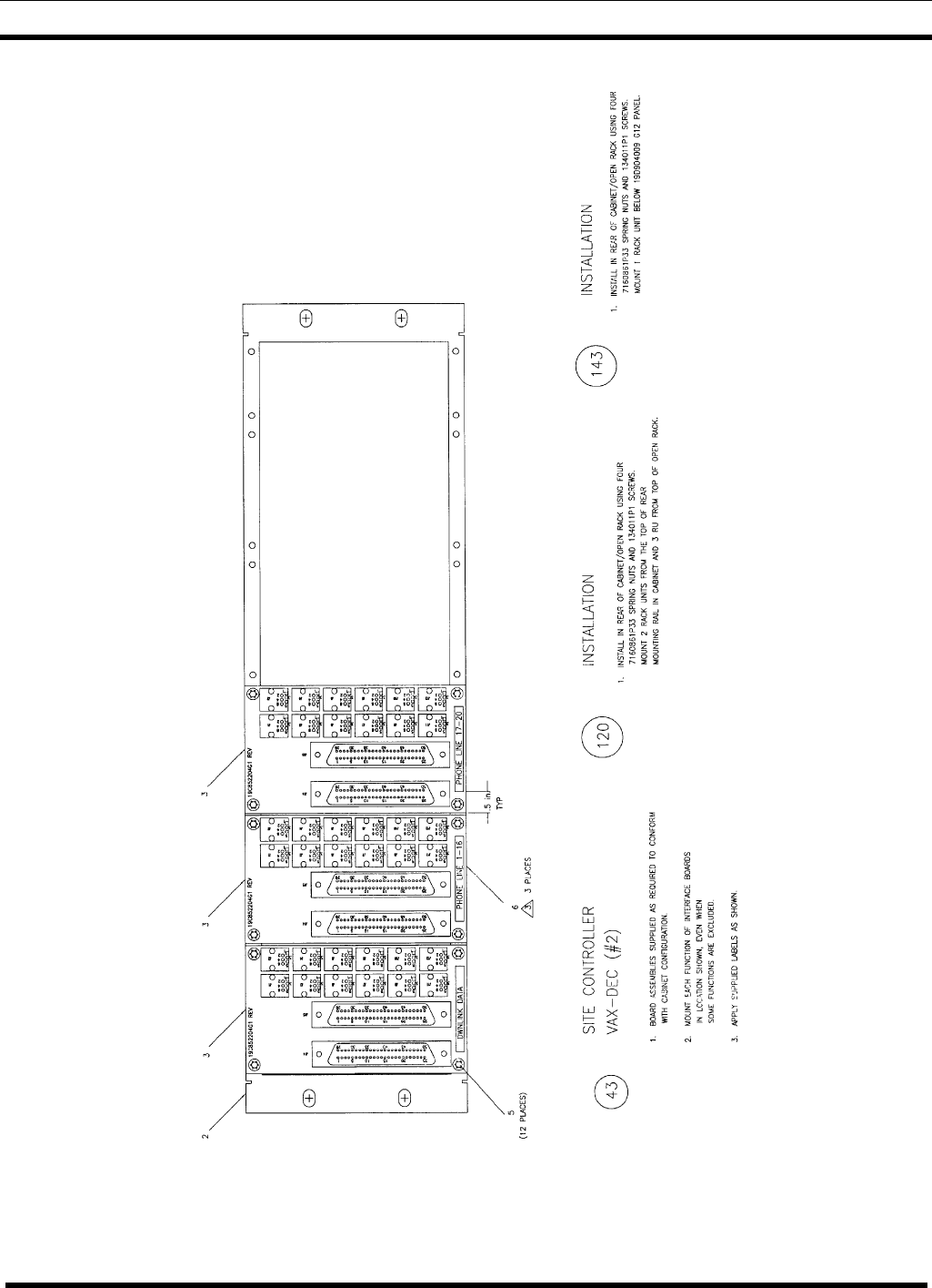
STATION ASSEMBLY DIAGRAM
24 LBI-38812K
EDACS INTERFACE PANEL (G13) – SITE CONTROLLER VAX-DEC (#2)
(19D904009, Sh. 13, Rev. 7)
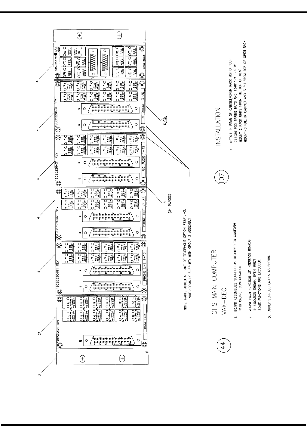
STATION ASSEMBLY DIAGRAM
LBI-38812K 25
EDACS INTERFACE PANEL (G14) – CTIS MAIN COMPUTER VAX-DEC
(19D904009, Sh. 14, Rev. 7
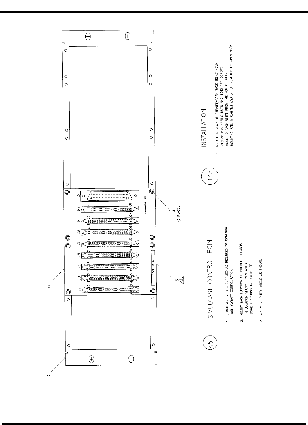
STATION ASSEMBLY DIAGRAM
26 LBI-38812K
EDACS INTERFACE PANEL (G15) – SIMULCAST CONTROL POINT
(19D904009, Sh. 15, Rev. 7)
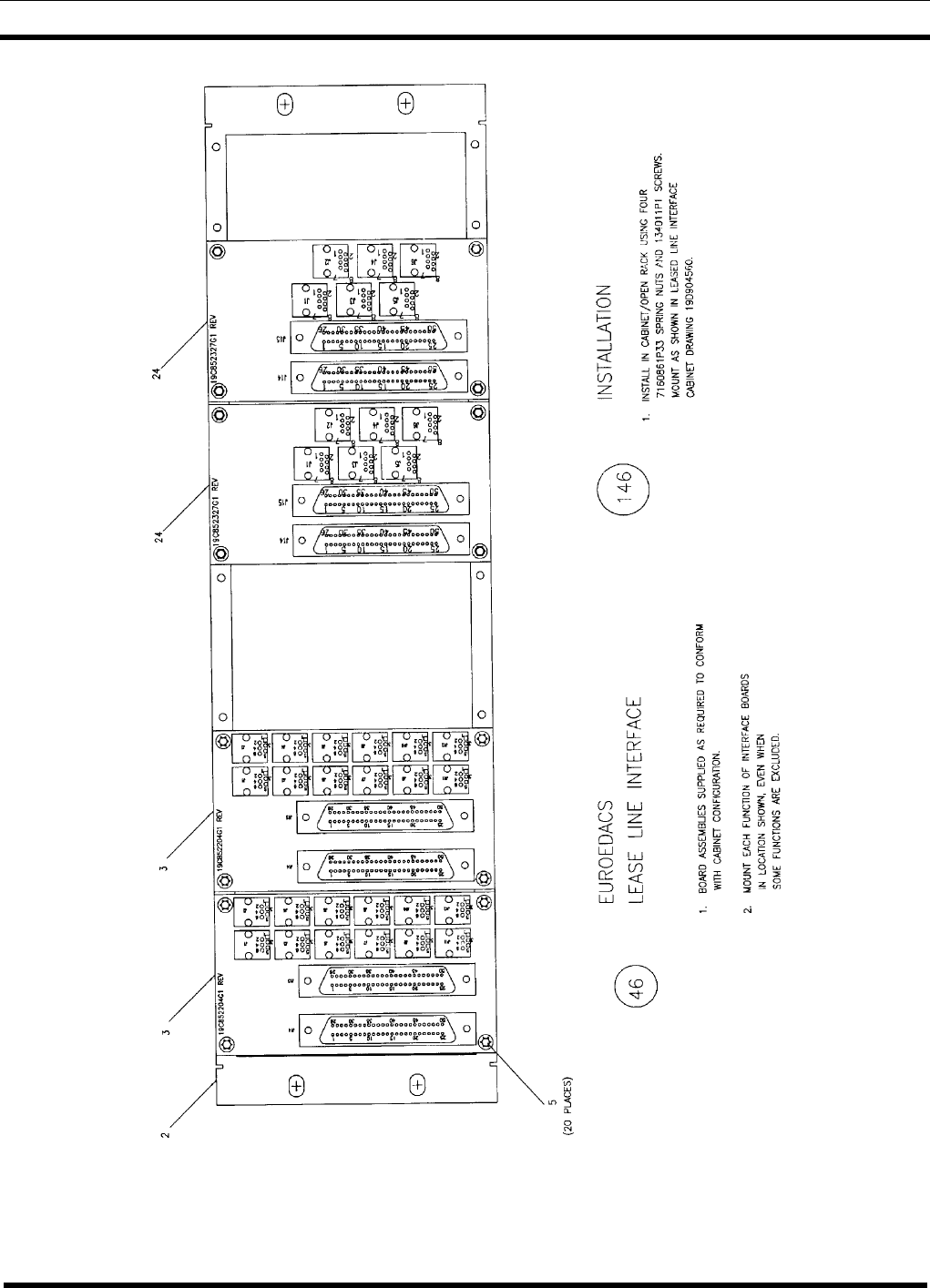
STATION ASSEMBLY DIAGRAM
LBI-38812K 27
EDACS INTERFACE PANEL (G16) – EURO EDACS LEASED LINE INTERFACE
(10D904009, Sh. 16, Rev. 7)
STATION ASSEMBLY DIAGRAM
28 LBI-38812K
EDACS INTERFACE PANEL (G17) – RIC TRANSFORMER PANEL
(19D904009, Sh. 17, Rev. 7)
STATION ASSEMBLY DIAGRAM
LBI-38812K 29
EDACS INTERFACE PANEL (G18) – JESSICA CONTROL
19D904009, Sh. 18, Rev.7)
STATION ASSEMBLY DIAGRAM
30 LBI-38812K
EDACS INTERFACE PANEL (G19) – DVIU INTERFACE PANEL
(19D904009, Sh. 19, Rev. 7)
STATION ASSEMBLY DIAGRAM
LBI-38812K 31
EDACS INTERFACE PANEL (G20) – STN VOTER INTERFACE
(19D904009, Sh. 20, Rev.7)
STATION ASSEMBLY DIAGRAM
32 LB-38812K
EDACS INTERFACE PANEL (G21) – VOTER RIC INTERFACE
19D904009, Sh. 21, Rev. 7)
STATION ASSEMBLY DIAGRAM
LBI-38812K 33
EDACS INTERFACE PANEL (G22) – AUXILIARY RECEIVER RS-232
(19D904009, Sh. 22, Rev. 7)
STATION ASSEMBLY DIAGRAM
34 LBI-38812K
EDACS INTERFACE PANEL (G23) – AUXILIARY RECEIVER C0ONVENTIONAL
(19D904009, Sh. 23, Rev.7)
STATION ASSEMBLY DIAGRAM
LBI-38812K 35
EDACS INTERFACE PANEL (G25) – SIMULCAST TX STE (RS-232 DATA)
(19D904009, Sh. 24, Rev. 7)
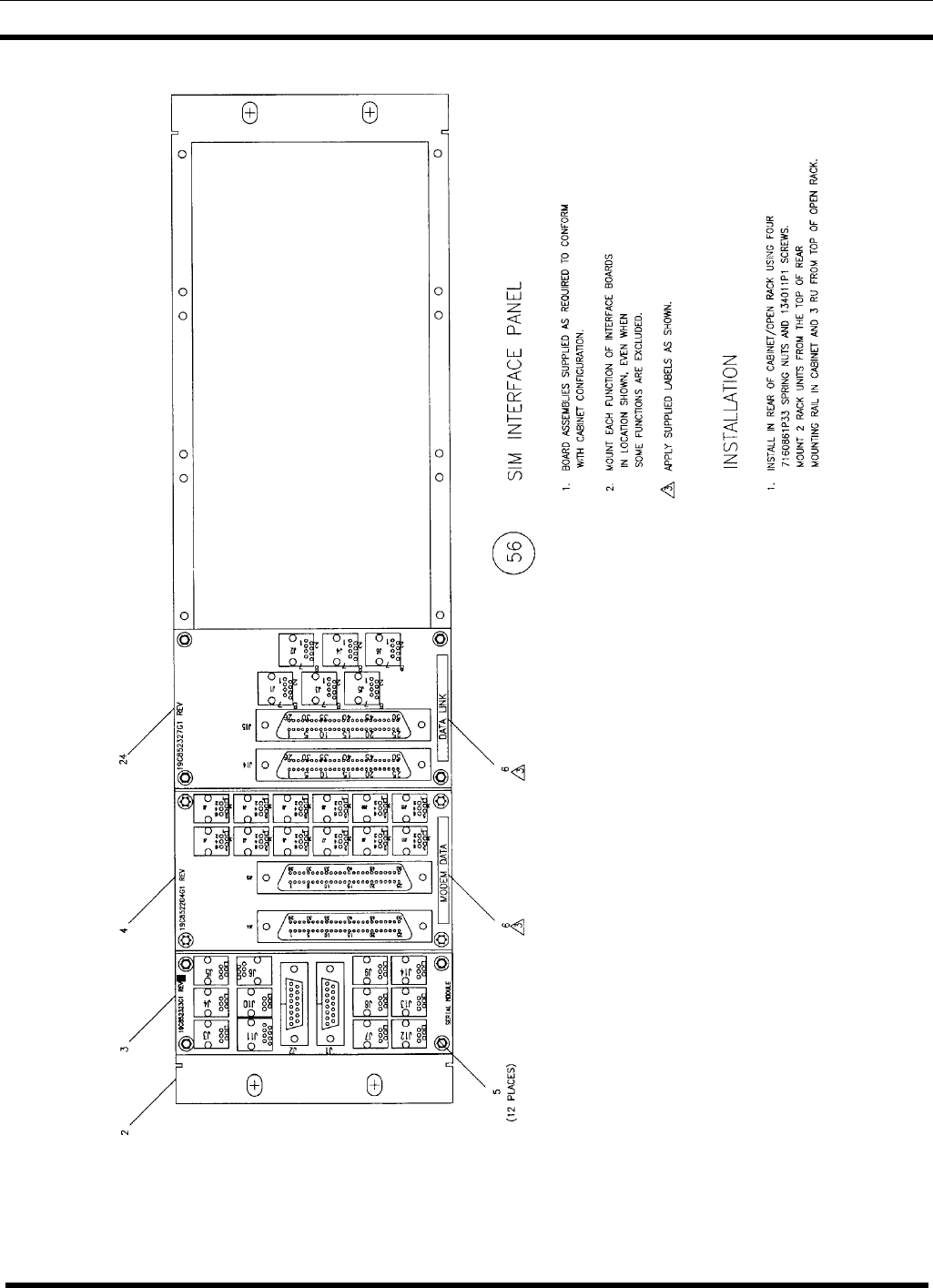
STATION ASSEMBLY DIAGRAM
36 LBI-38812K
EDACS INTERFACE PANEL (G26) – SIM INTERFACE PANEL
(19D904009, Sh. 25, Rev.7)
STATION ASSEMBLY DIAGRAM
LBI-38812K 37
EDACS INTERFACE PANEL (G28) – SITE SENTRY/ELI/SIM (MASTR III)
(19D904009, Sh. 26, Rev.7)
STATION ASSEMBLY DIAGRAM
38 LBI-38812K
EDACS INTERFACE PANEL (G29) – PRISM SITE SENTRY/SIM
(19D904009, Sh. 27, Rev. 7)
STATION ASSEMBLY DIAGRAM
LBI-38812K 39
EDACS INTERFACE PANEL (G30) – PRISM ELI AUDIO
(19D904009, Sh. 28, Rev. 7)
STATION ASSEMBLY DIAGRAM
40 LBI-38812K
EDACS INTERFACE PANEL (G31 & G32) – STATION ASSEMBLY WITH SITEPRO
(19D904009, Sh. 29, Rev. 7)

LBI-38812K 41
(This page intentionally left blank)

M/A-COM Wireless Systems
3315 Old Forest Road
Lynchburg, Virginia 24501
(Outside USA, 434-385-2400) Toll Free 800-528-7711
www.macom-wireless.com Printed in U.S.A.