HARRIS TR-0026-E Land Mobile Base Station User Manual Manual 4
HARRIS CORPORATION Land Mobile Base Station Manual 4
HARRIS >
Contents
- 1. Manual 1
- 2. Manual 2
- 3. Manual 3
- 4. Manual 4
Manual 4

Maintenance Manual
LBI-38775S
MASTR® III Base Station
Application/Assembly Diagrams
TABLE OF CONTENTS
Title Publication
T/R SHELF............................................................... LBI-38637
SYSTEM MODULE (Earlier) ................................. LBI-38764
SYSTEM MODULE (Later) .................................... LBI-39176
POWER MODULE .................................................. LBI-38752

TABLE OF CONTENTS
2LBI-38775S
TABLE OF CONTENTS
Page
SAFETY INFORMATION ..............................................................................................................................................3
INTRODUCTION ............................................................................................................................................................4
APPLICATIONS..............................................................................................................................................................5
APPLICATION ASSEMBLY DIAGRAMS....................................................................................................................7
37" INDOOR CABINET 19D902845P1 ......................................................................................................................7
T/R SHELF, SQUELCH OPERATED RELAY, DATA MODULE, AMPLIFIER MODULE & TRANSMIT
ONLY STATION 19D902845P2, P7, P14, P19 & P32 ...................................................................................13
COAX SWITCH ASSEMBLY 19D902845P3...........................................................................................................15
37" INDOOR CABINET WITH DUPLEXER SHELF 19D902845P4......................................................................16
37" INDOOR CABINET WITH AUTOMOBILE BATTERY EMERGENCY POWER 19D902845P5.................17
37" INDOOR CABINET WITH GEL CELL BATTERY EMERGENCY POWER 19D902845P6 .........................18
69" INDOOR CABINET WITH ONE STATION 19D902845P21............................................................................20
MASTR III STATION WITH MASTR II AUXILIARY RECEIVER 19D902845P8 ..............................................24
MASTR III TX P.A. aa57-HRB 10426 ...................................................................................................................... 25
MASTR III STATION WITH MASTR III MULTIPLE RECEIVER 19D902845P10..............................................27
69" INDOOR CABINET WITH GETC SHELF 19D902845P9 ................................................................................28
MASTR III BASE STATION WITH VOICE GUARD GETC MODULE 19D902845P11-P13 ..............................29
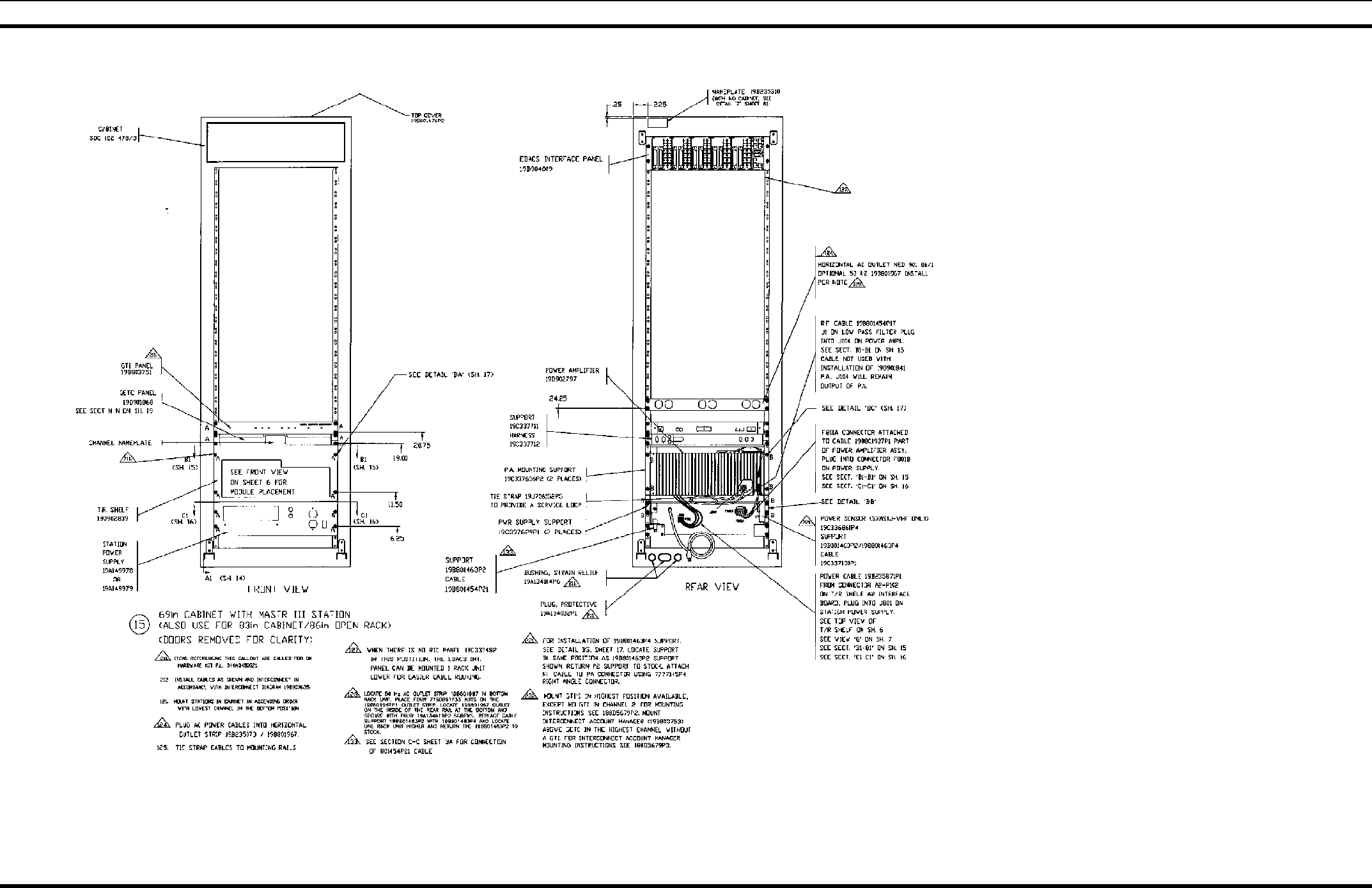
EDACS CABINET WITH ONE STATION 19D902845P15.....................................................................................31
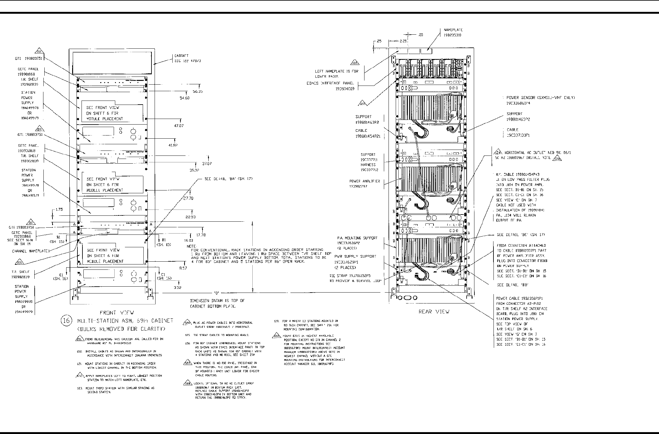
EDACS CABINET WITH MULTI-STATIONS 19D902845P16..............................................................................32
EDACS MULTI-STATION CABINET WITH SIM SHELF 19D902845P17........................................................... 34
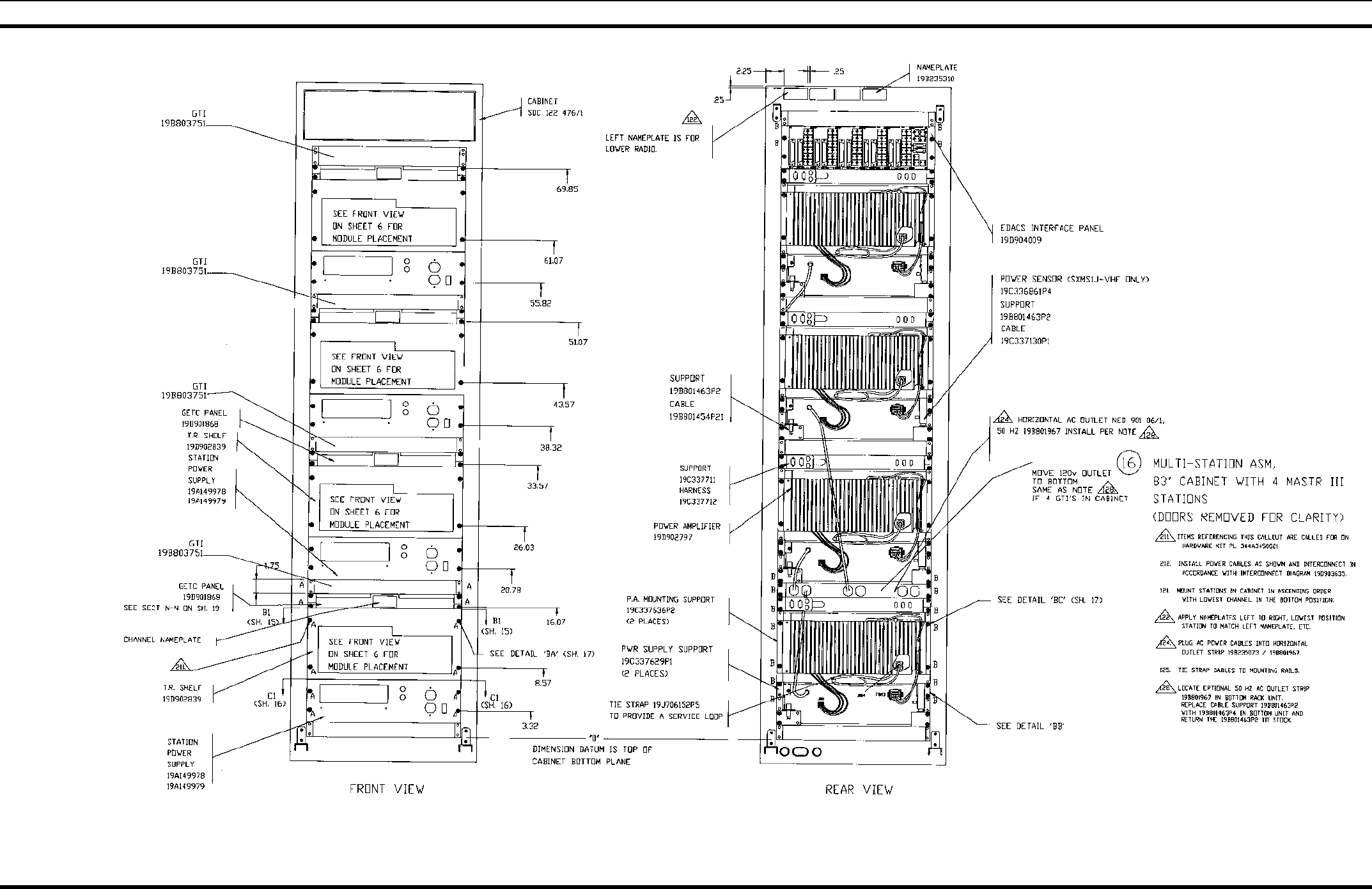
MULTI-STATION ASSEMBLY 19D902845P16 .....................................................................................................35
EXTERNAL REFERENCE OSCILLATOR/DISTRIBUTION AMPLIFIER OPTION 19D902845P18..................36
RS-232 SIMULCAST GETC 19D902845P22 ...........................................................................................................37
RIC EQUIPMENT 19D902845P23............................................................................................................................38
STATION RECEIVER VOTING FOR RS-232 19D902845P24...............................................................................39
EDACS SIMULCAST STATION 19D902845P22 & P33 ........................................................................................40
45" WEATHER PROOF CABINET 19D902845P25 ................................................................................................41
MODEM VOTING & CNI INSTALLATION 19D902845P26 & P27......................................................................42
3 EDACS ADVANTAGE STATIONS 19D902845P29 ............................................................................................43
3/5 CHANNEL EDACS SYSTEM - COMBINER/MULTICOUPLER CHANNEL 4 & 5 19D902845P28 &
P30 ....................................................................................................................................................................44
3/4 CHANNEL EDACS SYSTEM - COMBINER AND MULTICOUPLER 19D902845P33................................. 45
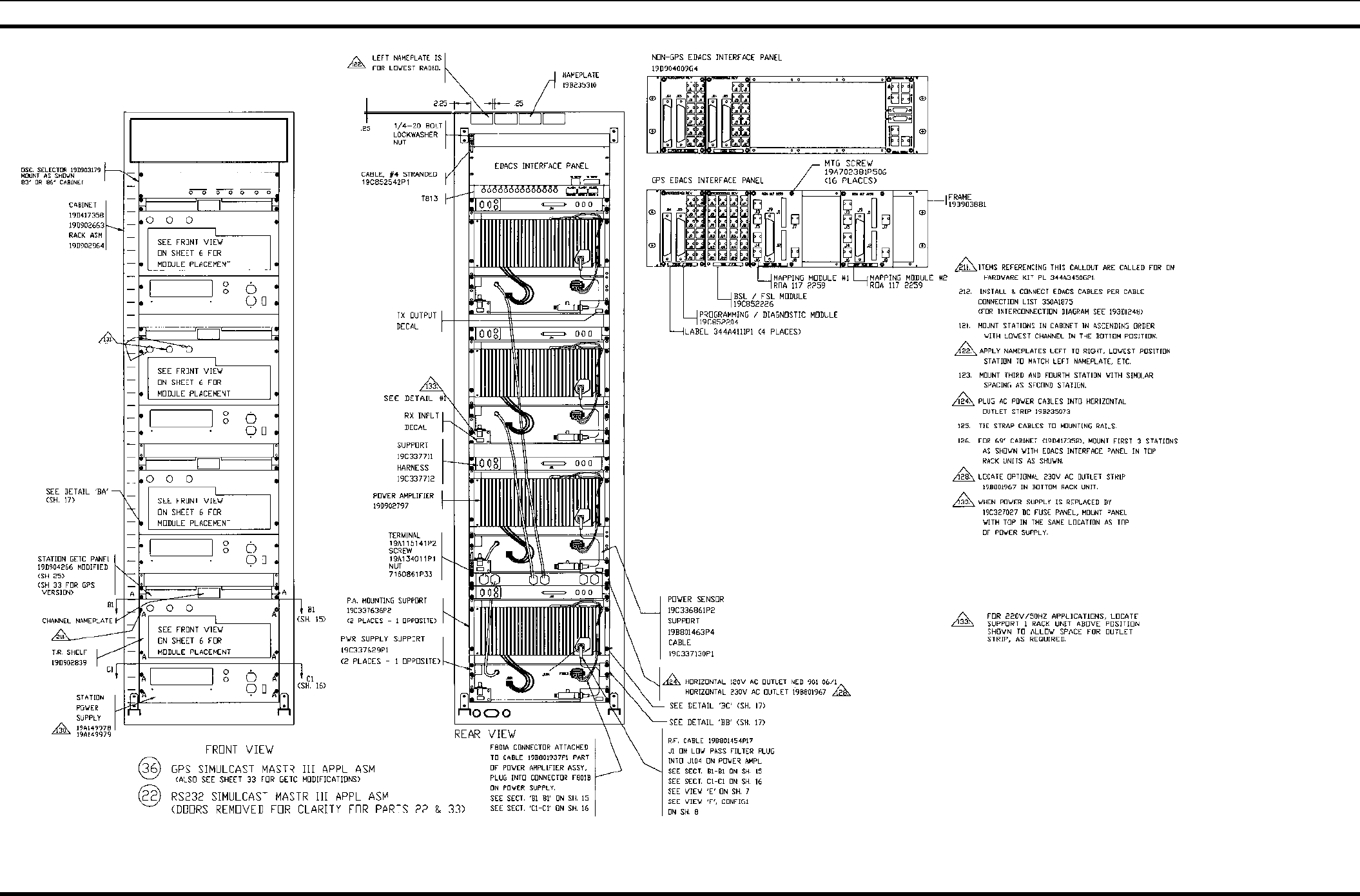
GPS SIMULCAST STATION GETC 19D902845P33 ..............................................................................................46
HARNESS 19C337792P1 ..............................................................................................................................................47
19B801454P16 & P17 ................................................................................................................................................48
19B801454P17 & P18 ................................................................................................................................................48
19B801454P19 & P20 ................................................................................................................................................48
19B801454P24 ...........................................................................................................................................................48
CONTROL CABLE ASSEMBLY (PART OF POWER AMPLIFIER) 19B801739P1.............................................48
POWER CABLE (PART OF POWER AMPLIFIER) 19B801937P1........................................................................49
19B235871P1 .............................................................................................................................................................49
344A3052P1 ...............................................................................................................................................................49
CONTROL EXTENDER BOARD 188D5338G1..........................................................................................................50
RF EXTENDER BOARD 188D5338G2........................................................................................................................50
MULTI PURPOSE MODULE 193D1094G1.................................................................................................................51
GROUNDING STRAP INSTALLATION INSTRUCTIONS .......................................................................................52
This manual is published by M/A-COM Private Radio Systems, Inc., without any warranty. Improvements and changes to this manual necessitated by
typographical errors, inaccuracies of current information, or improvements to programs and/or equipment, may be made by M/A-COM Private Radio
Systems, Inc., at any time and without notice. Such changes will be incorporated into new editions of this manual. No part of this manual may be
reproduced or transmitted in any form or by any means, electronic or mechanical, including photocopying and recording, for any purpose, without the
express written permission of M/A-COM Private Radio Systems, Inc.
Copyright 1992-2002, M/A-COM Private Radio Systems, Inc. All rights reserved.
INTRODUCTION & APPLICATIONS
LBI-38775S 3
SAFETY INFORMATION
• The means of disconnecting power from a station cabinet is the cabinet power supply plug.
• When conducting repair/maintenance, disconnect the cabinet power supply plug from the AC source.
• In European applications, equipment must be installed in a closed cabinet.
• Only replace components with components specified by M/A-COM Private Radio Systems.
The ESD symbol calls attention to procedures, practices, or the like, which
could expose equipment to the effects of Electro-Static Discharge. Proper
precautions must be taken to prevent ESD when handling circuit modules.
CAUTION – This radio contains components that can be damaged by the
effects of Electrostatic Discharge (ESD). Be sure to use proper precautions
when disassembling this equipment.
ESD CAUTION:
When operating the MASTR III System module, ESD precautions must be observed to insure that the unit
continues to function correctly. Due to ESD sensitive components, an ESD event could cause the MASTR
III to operate improperly. To prevent this from occurring, ESD precautions are required. These
precautions would include but are not limited to:
• The use of an ESD wrist strap connected to any attachable metallic surface on the rack chassis, housing
the MASTR III equipment.
The ESD caution is being provided to avoid inducing an equipment malfunction by an ESD event. If an
ESD induced malfunction occurs, there will be no permanent damage to the unit, but manual reset will be
necessary.

INTRODUCTION & APPLICATIONS
4LBI-38775S
INTRODUCTION
This manual (LBI-38775) contains information for the MASTR III Base Station, including
application information, cable diagrams and parts list for the cabinet hardware. For
additional information refer to the following manuals:
MANUAL
NUMBER
TITLE COMMENTS
LBI-38636 Installation How to install including Interconnection
Diagrams.
AE/LZT 123 3242/1 Installation Installation, Configuration and Checkout
for EDACS Basic or Level 1 Systems.
LBI-38754 VHF RF Package Information on the VHF equipment.
LBI-38675 UHF RF Package Information on the UHF equipment.
LBI-39025 800 MHz RF
Package
Information on the 800 MHz equipment.
LBI-38983 Antenna System Information on typical antenna system
installations.
LBI-38812 EDACS Interface
Panels
Information on the panel used in EDACS
applications.
LBI-38894 GETC Information on the GETC equipment
LBI-38625 Charger/Emergency
power
Information on the battery charger and
emergency power equipment.
LBI-38805 RF Test Fixture Information on the RF Test Fixture

INTRODUCTION & APPLICATIONS
LBI-38775S 5
APPLICATIONS
OPTION
NUMBER
APPLICATION
ASSEMBLY
DESCRIPTION
SXCAIS 19D902845P1 Installation of One MASTR III Station in
a 37" Indoor Cabinet
SXRB1J 19D902845P2 Installation of R/R Shelf for MASTR III
Station.
SXSU3A 19D902845P3 Installation of Coax Switch.
SXDU1J 19D902845P4 Installation UHF (150-162 MHz )
Duplexer
SXDU1K Installation UHF (152-174 MHz )
Duplexer
SXDU1M Installation UHF (450-470 MHz )
Duplexer
SXCH1L/M 19D902845P5 Installation of Battery Charger with
Automobile Battery Emergency Power in
a 37" Indoor Cabinet.
SXCH1R
SXCH3A
19D902845P6 Installation of Battery Charger with Gel
Cell Battery Emergency Power in a 37"
Indoor cabinet.
SXSU3D 19D902845P7 Installation of SOR (Squelch Operated
Relay) Kit.
SXMK3C 19D902845P8 Installation of MASTR II Auxiliary
Receiver in a 37" or 69" Cabinet.
SXCP5T
SXMD3J
19D902845P9 Installation of GETC Shelf in a 69"
Indoor Cabinet.
SXMIL3S 19D902845P10 Installation of MASTR III auxiliary
Receiver in a 37" or 69" Cabinet
SXVG3E
SXVG3F
19D902845P11 Installation of GETC Shelf for an E/E
Voice Guard/Aegis Repeater and
Remote/Repeater in a 37" or 69" Indoor
Cabinet.
SXVV1N
SXVV1M
SXVV1S
SXVW1J
19D902845P12 Installation of E/D Module (non-1027
version) in a 37" or 69" Indoor Cabinet
(Aegis Remote/Remote/Repeat MASTR
III).
SXVG3C
SXVG3D
19D902845P13 Installation of E/D module (1027
version) in a 37" or 69" Indoor Cabinet
(Remote E/D & Remote/Repeat).
SXDE5B 19D902845P14 Installation of Transmit Data Board.
SXAP3K 19D902845P16 Installation of Multi-Stations in a 69" or
83" Indoor Cabinet or Open Rail Rack.

INTRODUCTION & APPLICATIONS
6LBI-38775S
OPTION
NUMBER
APPLICATION
ASSEMBLY
DESCRIPTION
19D902845P21 Installation in 69" Indoor Cabinet or
Open Rail Rack.
SXMD3M 19D902845P22 Installation for Simulcast Stations.
SXMD1S 19D902845P23 Installation and Modifications Instruction
for RIC Telephone Interconnect.
SXVT1B 19D902845P24 Modification for Station Receiver Voting
for RS-232.
SXCA1X 19D902845P25 Installation in 45" Weatherproof Cabinet.
SXVT1L 19D902845P26 Modem Voting Installation.
SXCP5T 19D902845P27 CNI Installation.
SXFN1A 2-Speed Fan (110 VAC).
SXFA1L 2-Speed Fan (230 VAC).
SXCY1S 19D902845P17 MASTR III with SIM Shelf.
19D902845P18 MASTR III Reference
Oscillator/Distribution Amplifier.
APPLICATION ASSEMBLY DIAGRAM
LBI-38775S 7
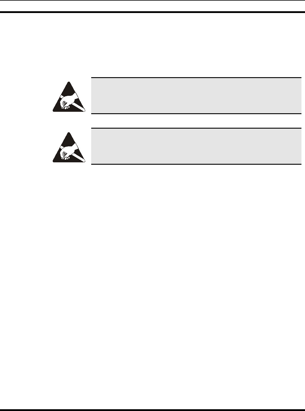
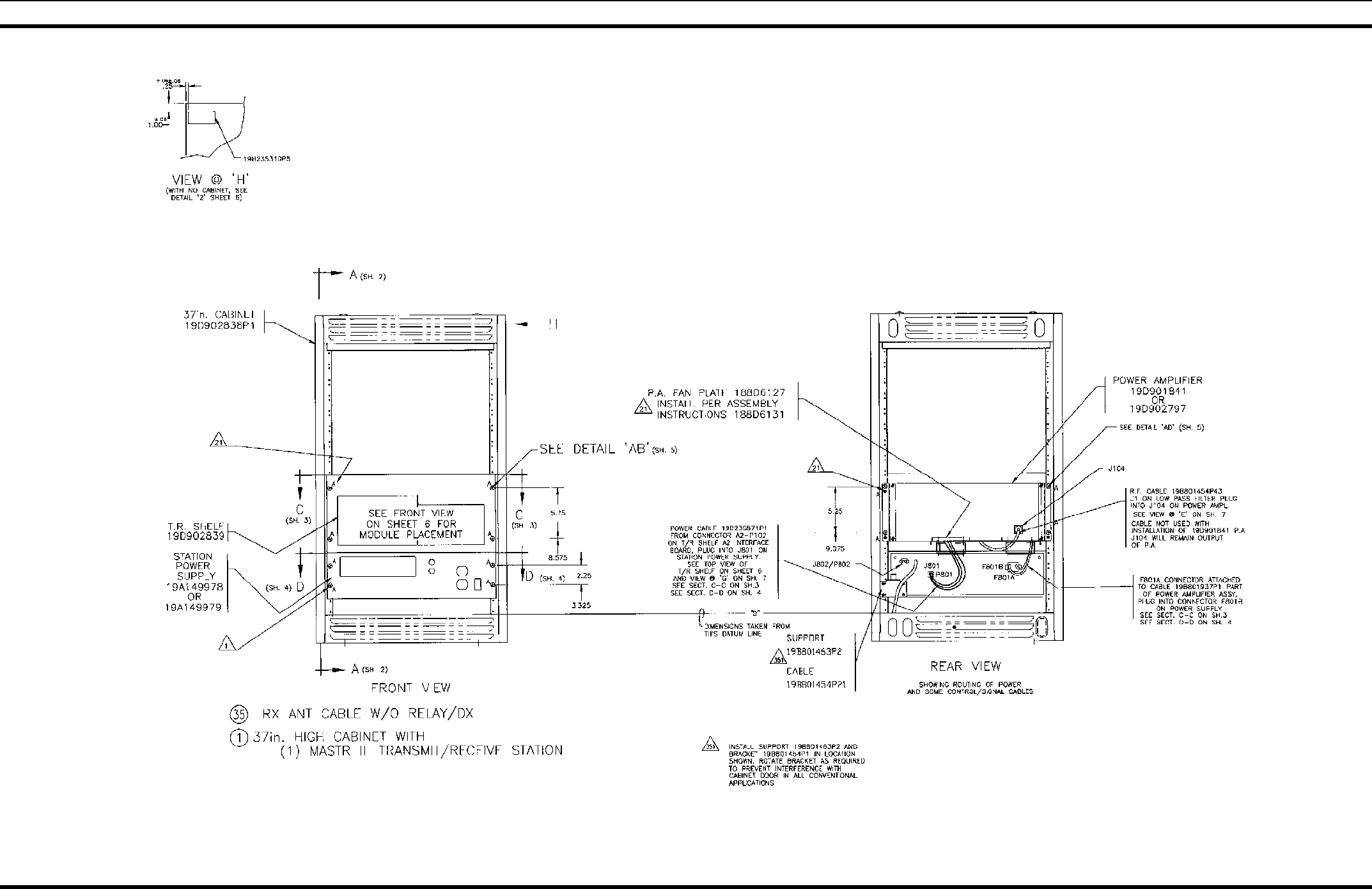
37" INDOOR CABINET
19D902845P1
(19D902845, Sh. 1, Rev. 12)
APPLICATION ASSEMBLY DIAGRAM
8LBI-38775S
37" INDOOR CABINET
19D902845P1
(19D902845, Sh. 2, Rev. 3)
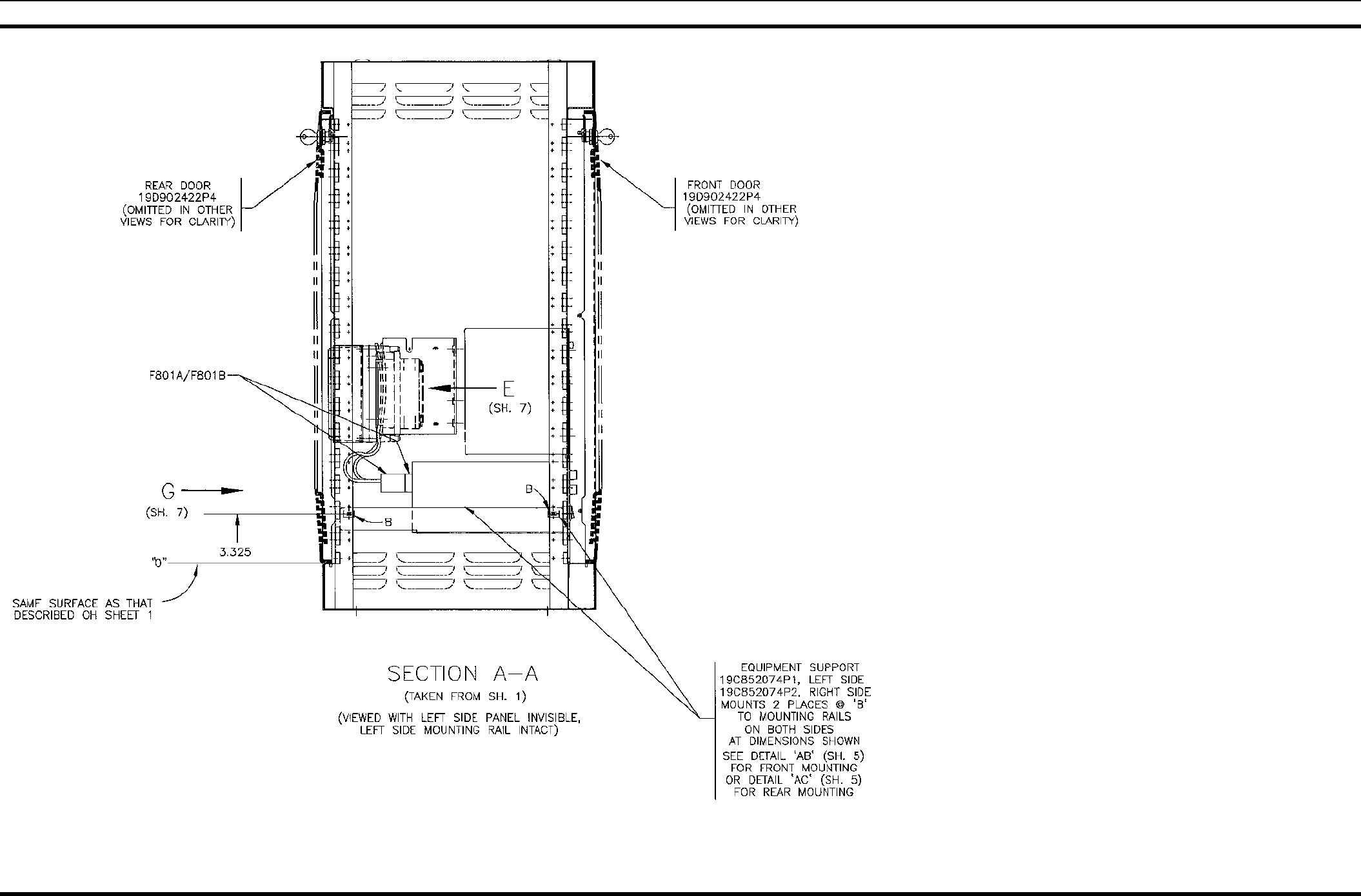
APPLICATION ASSEMBLY DIAGRAM
LBI-38775S 9
37" INDOOR CABINET
19D902845P1
(19D902845, Sh. 3, Rev. 7)
APPLICATION ASSEMBLY DIAGRAM
10 LBI-38775S
37" INDOOR CABINET
19D902845P1
(19D902845, Sh. 3A, Rev. 4)
APPLICATION ASSEMBLY DIAGRAM
LBI-38775S 11
37" INDOOR CABINET
19D902845P1
(19D902845, Sh. 4, Rev. 2)
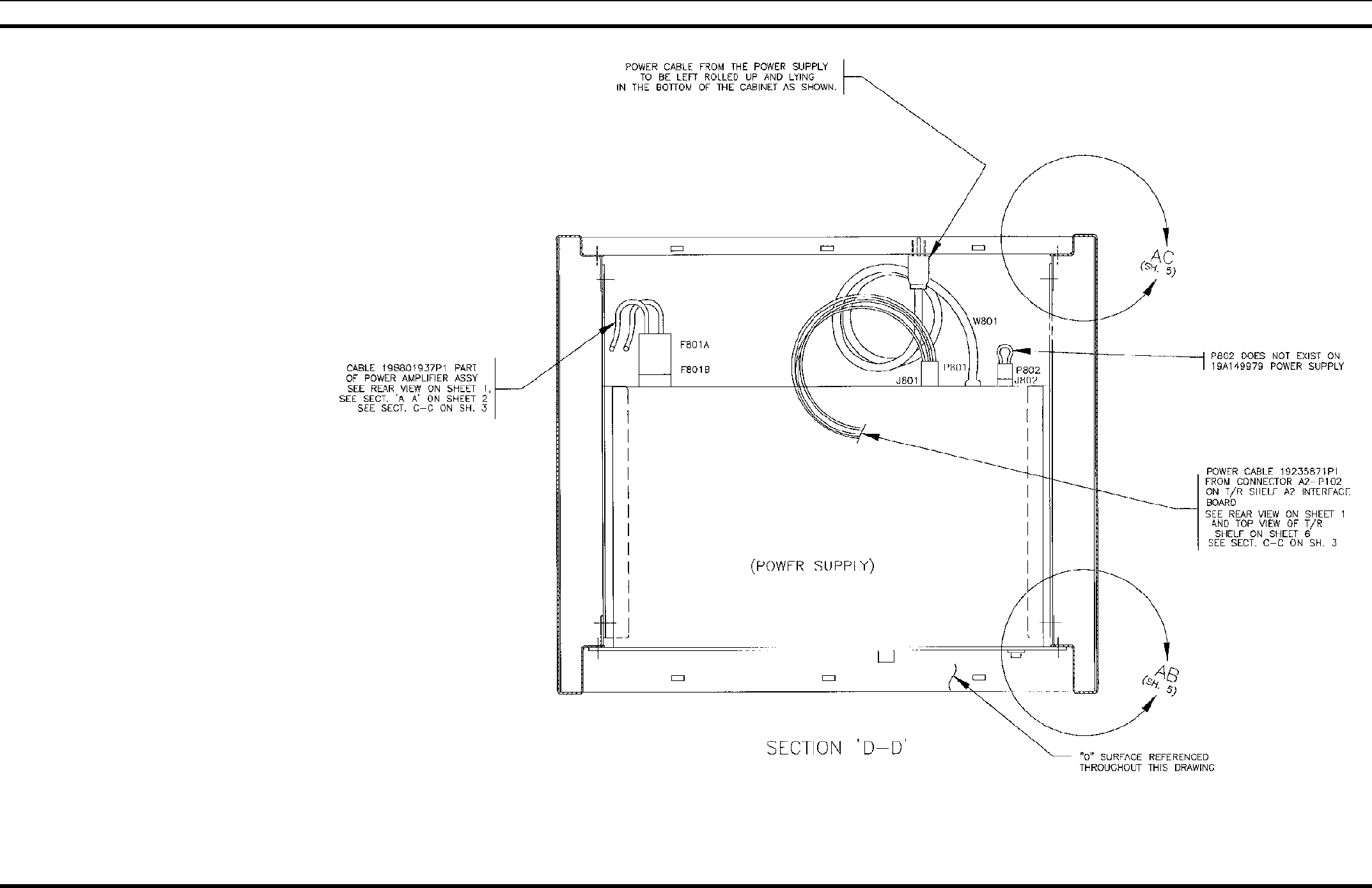
APPLICATION ASSEMBLY DIAGRAM
12 LBI-38775S
37" INDOOR CABINET
19D902845P1
(19D902845, Sh. 5, Rev. 5)
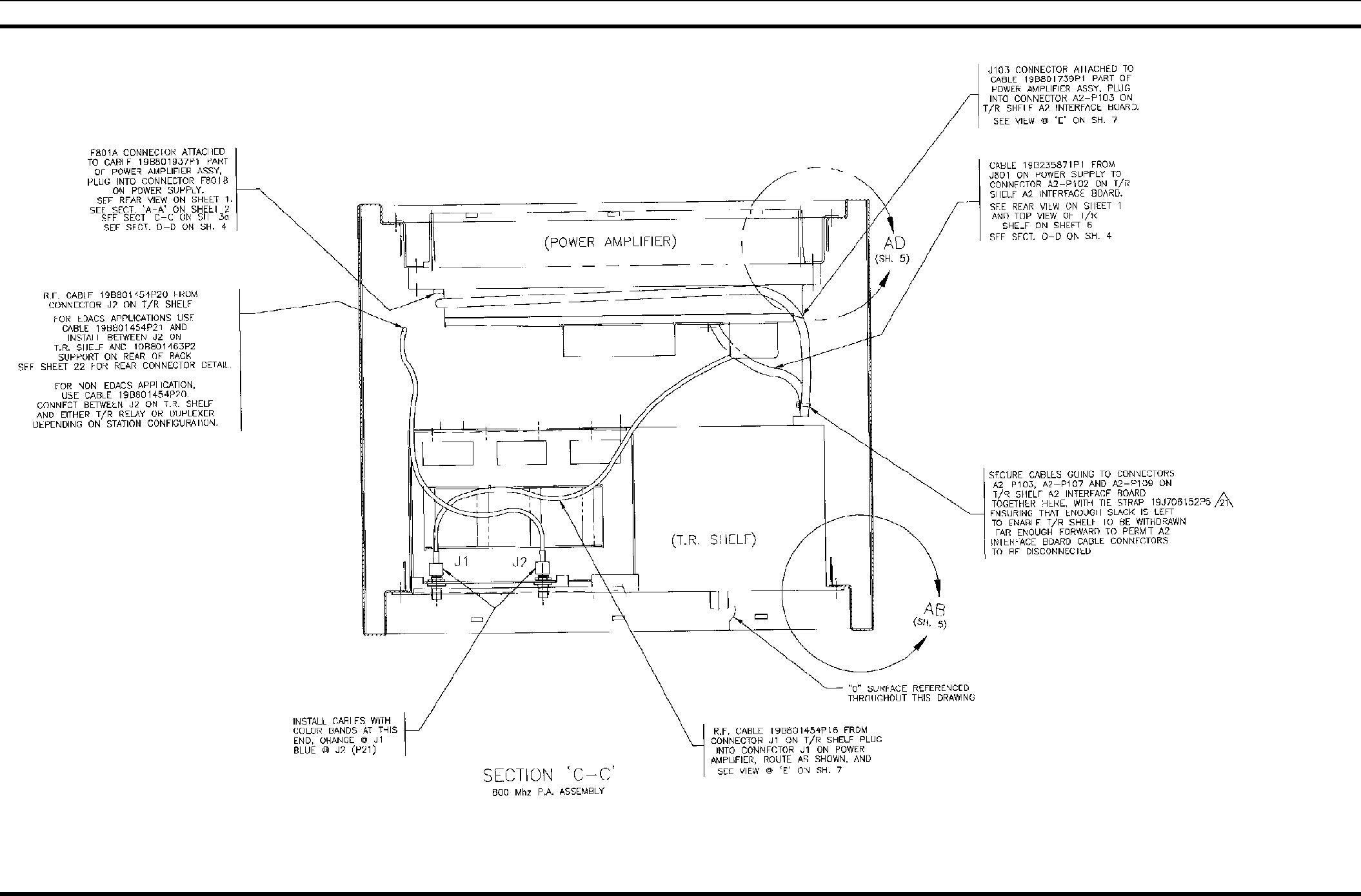
APPLICATION ASSEMBLY DIAGRAM
LBI-38775S 13
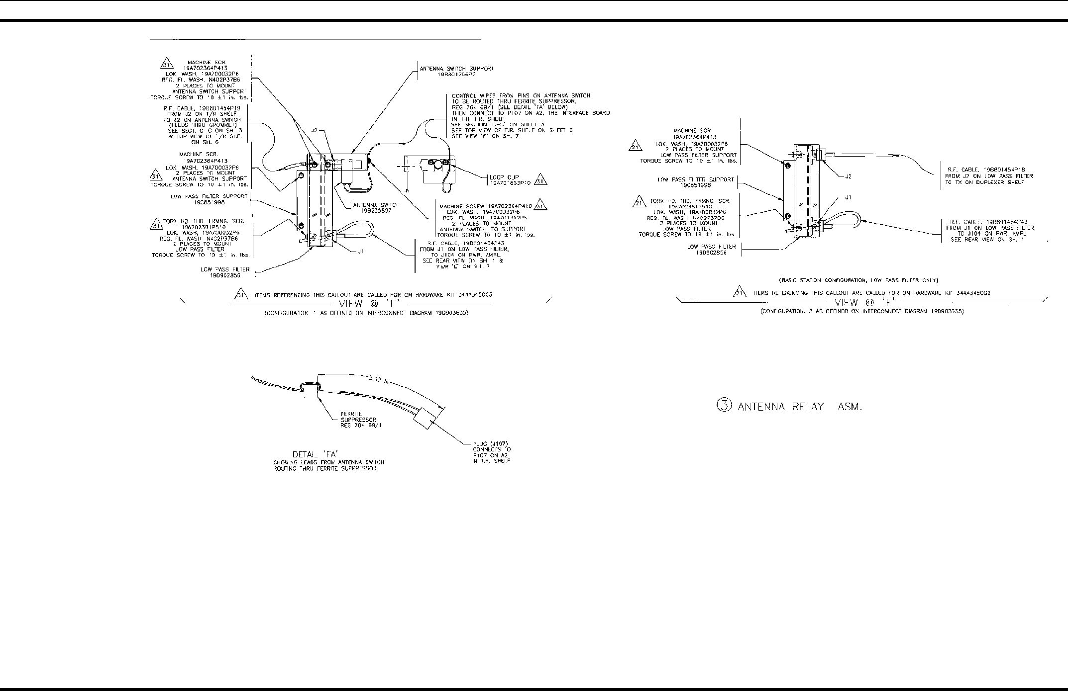
T/R SHELF, SQUELCH OPERATED RELAY, DATA MODULE, AMPLIFIER MODULE & TRANSMIT ONLY STATION
19D902845P2, P7, P14, P19 & P32
(19D902845, Sh. 6, Rev. 12)
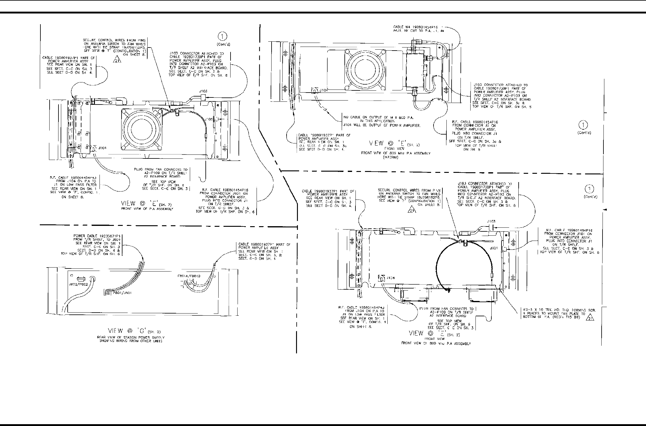
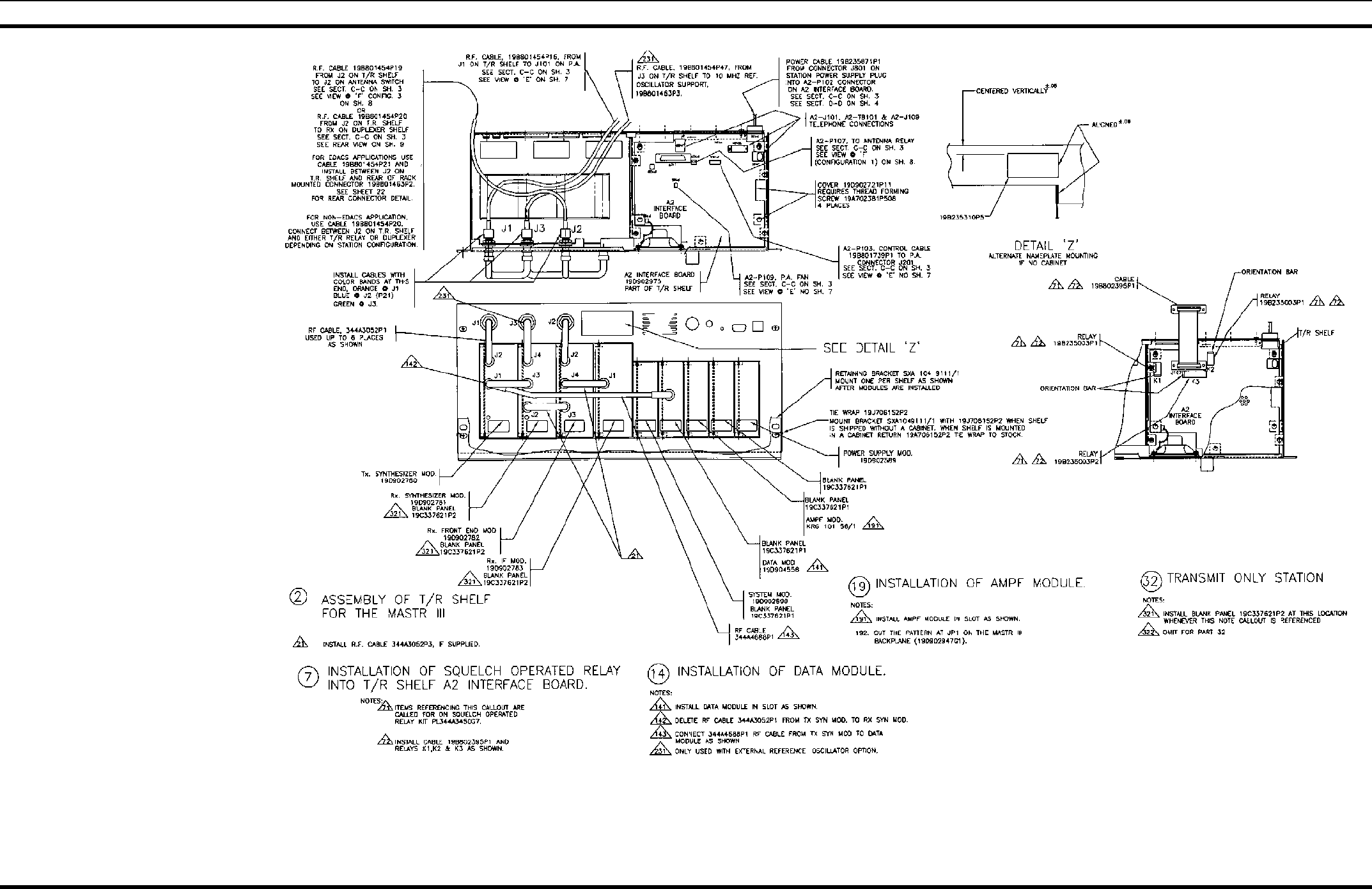
APPLICATION ASSEMBLY DIAGRAM
14 LBI-38775S
T/R SHELF, SQUELCH OPERATED RELAY, DATA MODULE, AMPLIFIER MODULE & TRANSMIT ONLY STATION
19D902845P2, P7, P14, P19 & P32
(19D902845, Sh. 7, Rev. 7)
APPLICATION ASSEMBLY DIAGRAM
LBI-38775S 15
COAX SWITCH ASSEMBLY 19D902845P3
(19D902845, Sh. 8, Rev. 8)
APPLICATION ASSEMBLY DIAGRAM
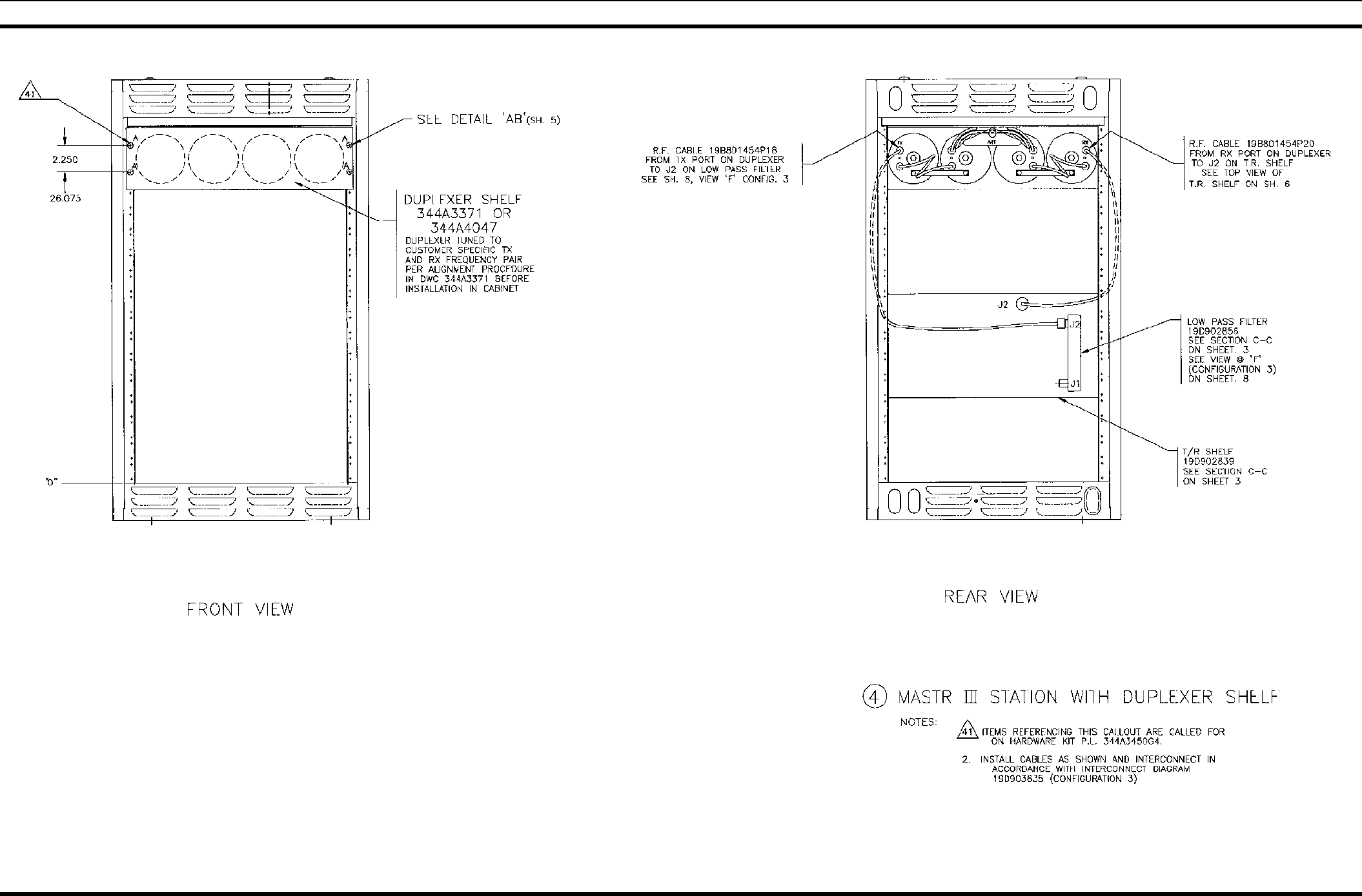
16 LBI-38775S
37" INDOOR CABINET WITH DUPLEXER SHELF
19D902845P4
(19D902845,Sh. 9, Rev. 4)
APPLICATION ASSEMBLY DIAGRAM
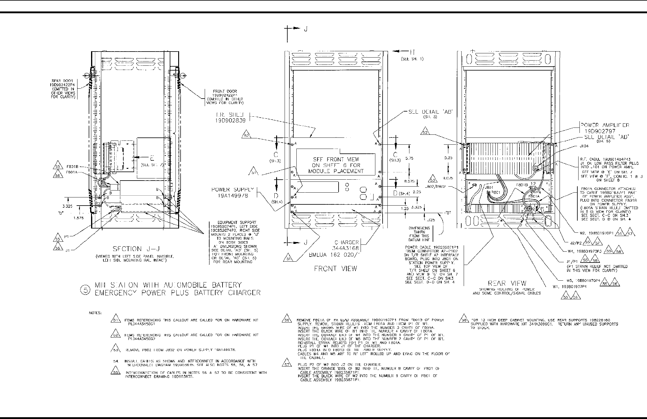
LBI-38775S 17
37" INDOOR CABINET WITH AUTOMOBILE BATTERY EMERGENCY POWER
19D902845P5
(19D902845, Sh. 10, Rev. 3)
APPLICATION ASSEMBLY DIAGRAM
18 LBI-38775S
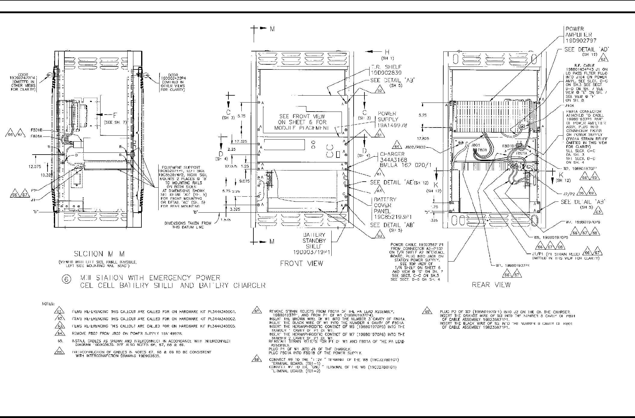
37" INDOOR CABINET WITH GEL CELL BATTERY EMERGENCY POWER
19D902845P6
(19D902845, Sh. 11, Rev. 2)
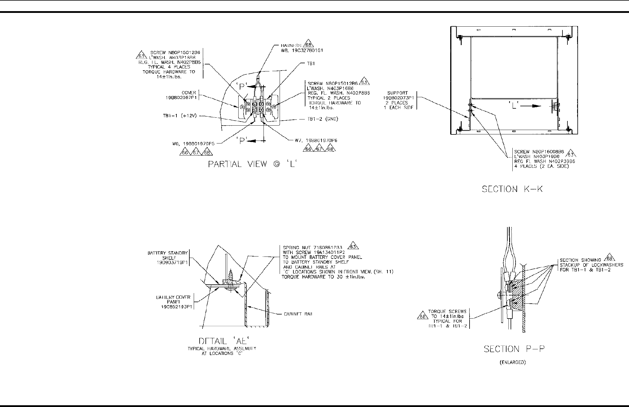
APPLICATION ASSEMBLY DIAGRAM
LBI-38775S 19
37" INDOOR CABINET WITH GEL CELL BATTERY EMERGENCY POWER
19D902845P6
(19D902845, Sh. 12, Rev. 2)
APPLICATION ASSEMBLY DIAGRAM
20 LBI-38775S
69" INDOOR CABINET WITH ONE STATION
19D902845P21
(19D902845, Sh. 15, Rev. 6)
APPLICATION ASSEMBLY DIAGRAM
LBI-38775S 21
69" INDOOR CABINET WITH ONE STATION
19D902845P21
(19D902845, Sh. 15A, Rev. 4)
APPLICATION ASSEMBLY DIAGRAM
22 LBI-38775S
69" INDOOR CABINET WITH ONE STATION
19D902845P21
(19D902845, Sh. 16, Rev. 3)
DETAIL “H”
APPLICATION ASSEMBLY DIAGRAM
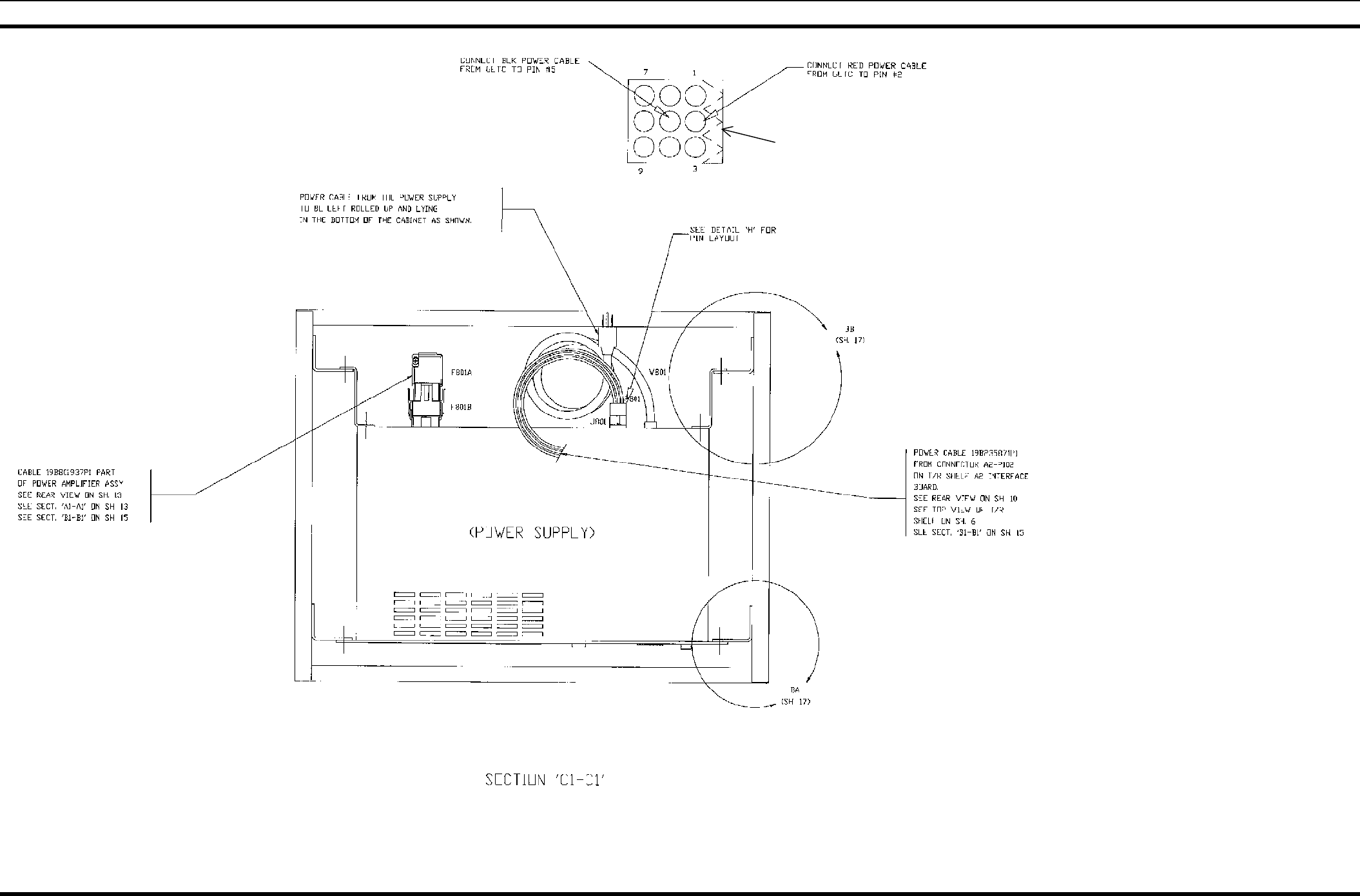
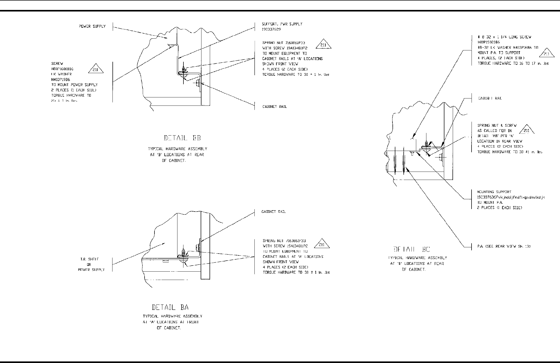
LBI-38775S 23
69" INDOOR CABINET WITH ONE STATION
19D902845P21
(19D902845, Sh. 17, Rev. 2)
APPLICATION ASSEMBLY DIAGRAM
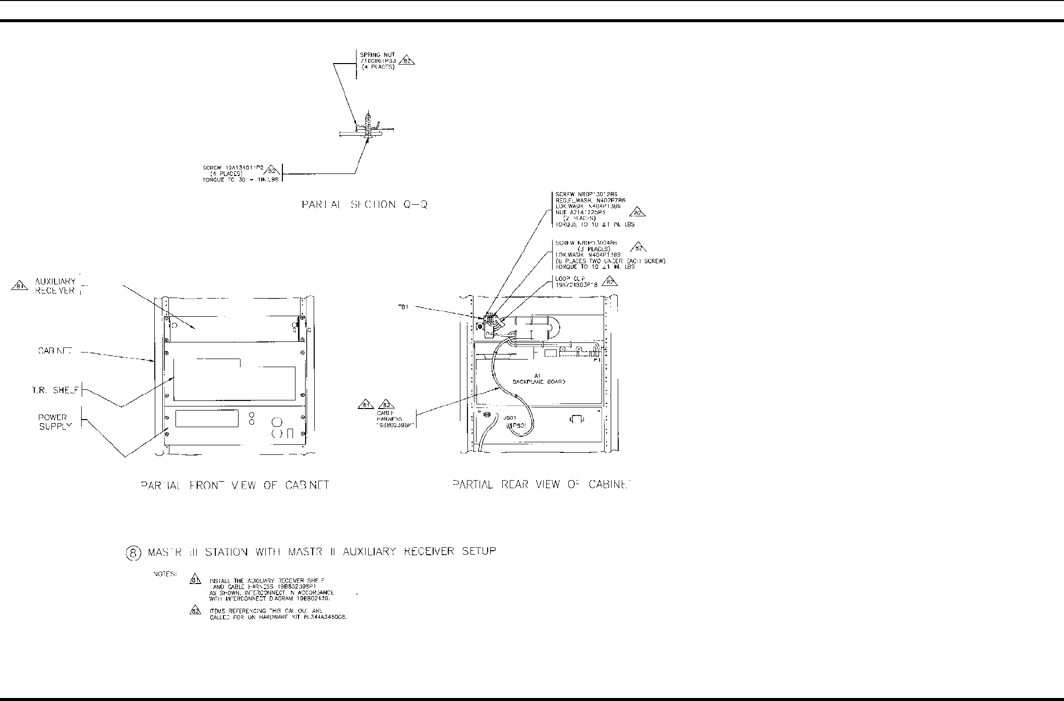
24 LBI-38775S
MASTR III STATION WITH
MASTR II AUXILIARY RECEIVER
19D902845P8
(19D902845, Sh. 18, Rev. 4)
APPLICATION ASSEMBLY DIAGRAM
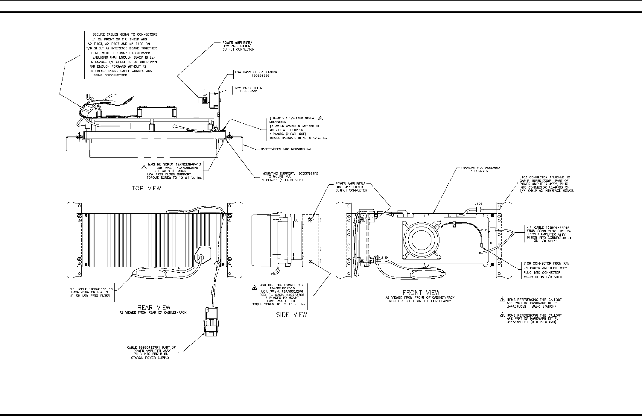
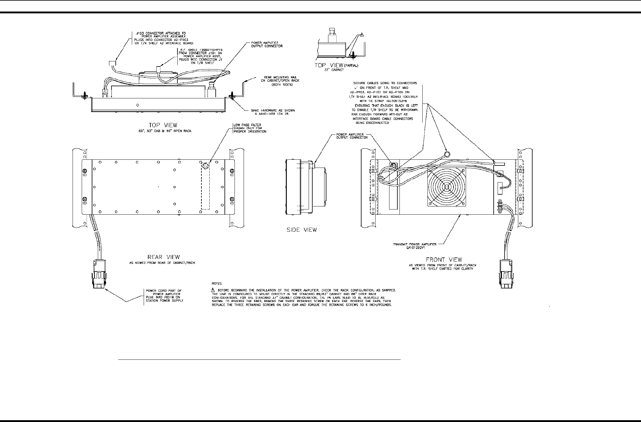
LBI-38775S 25
MASTR III TX P.A.
AA57-HRB 10426
Sheet 1 0f 2
(AA57-HRB 10426 Rev C)
APPLICATION ASSEMBLY DIAGRAM
26 LBI-38775S
MASTR III TX P.A.
AA57-HRB 10426
Sheet 2 0f 2
(AA57-HRB 10426 Rev C)
APPLICATION ASSEMBLY DIAGRAM
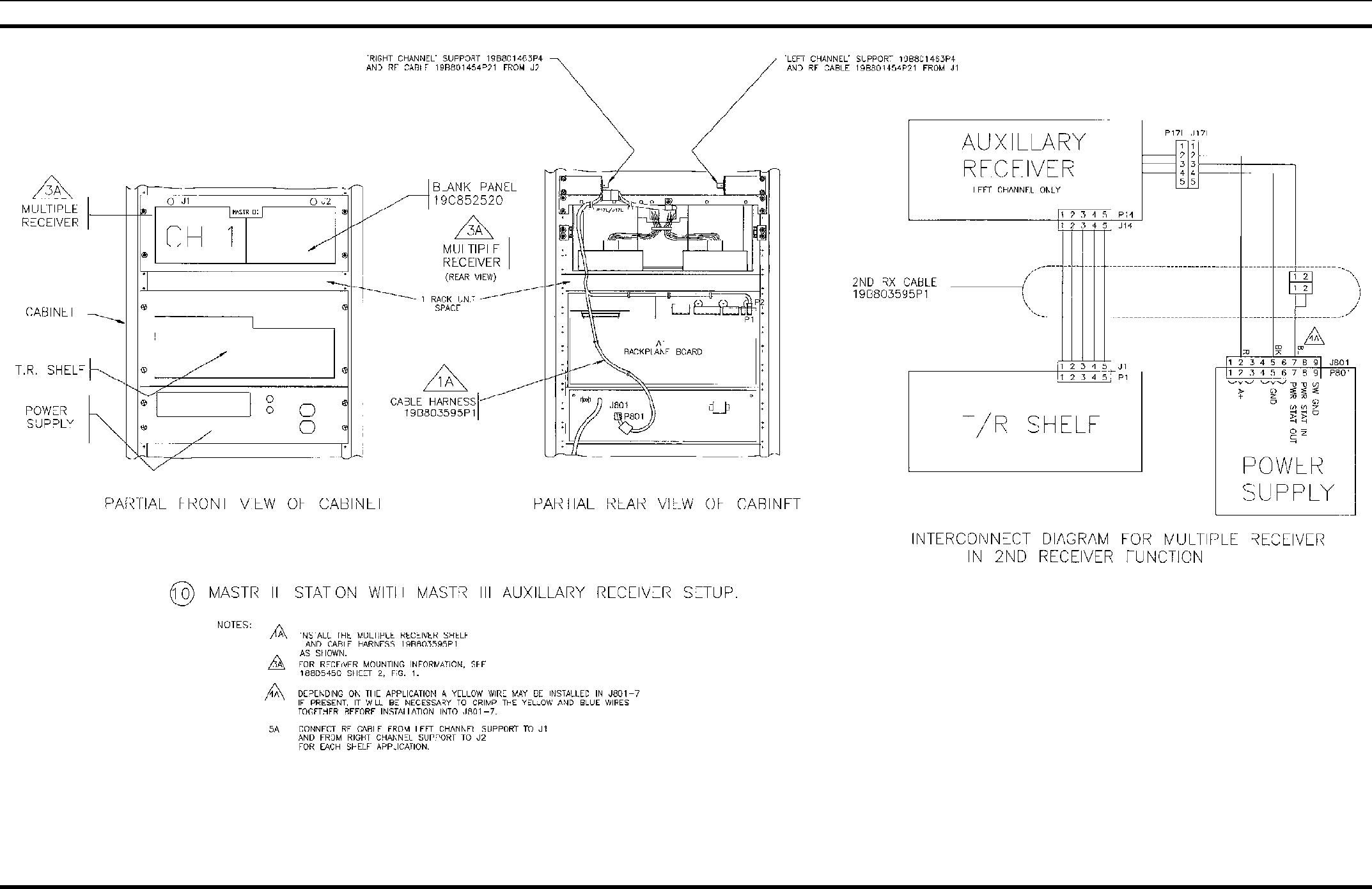
LBI-38775S 27
MASTR III STATION WITH
MASTR III MULTIPLE RECEIVER
19D902845P10
(19D902845, Sh. 18A, Rev. 6)
APPLICATION ASSEMBLY DIAGRAM
28 LBI-38775S
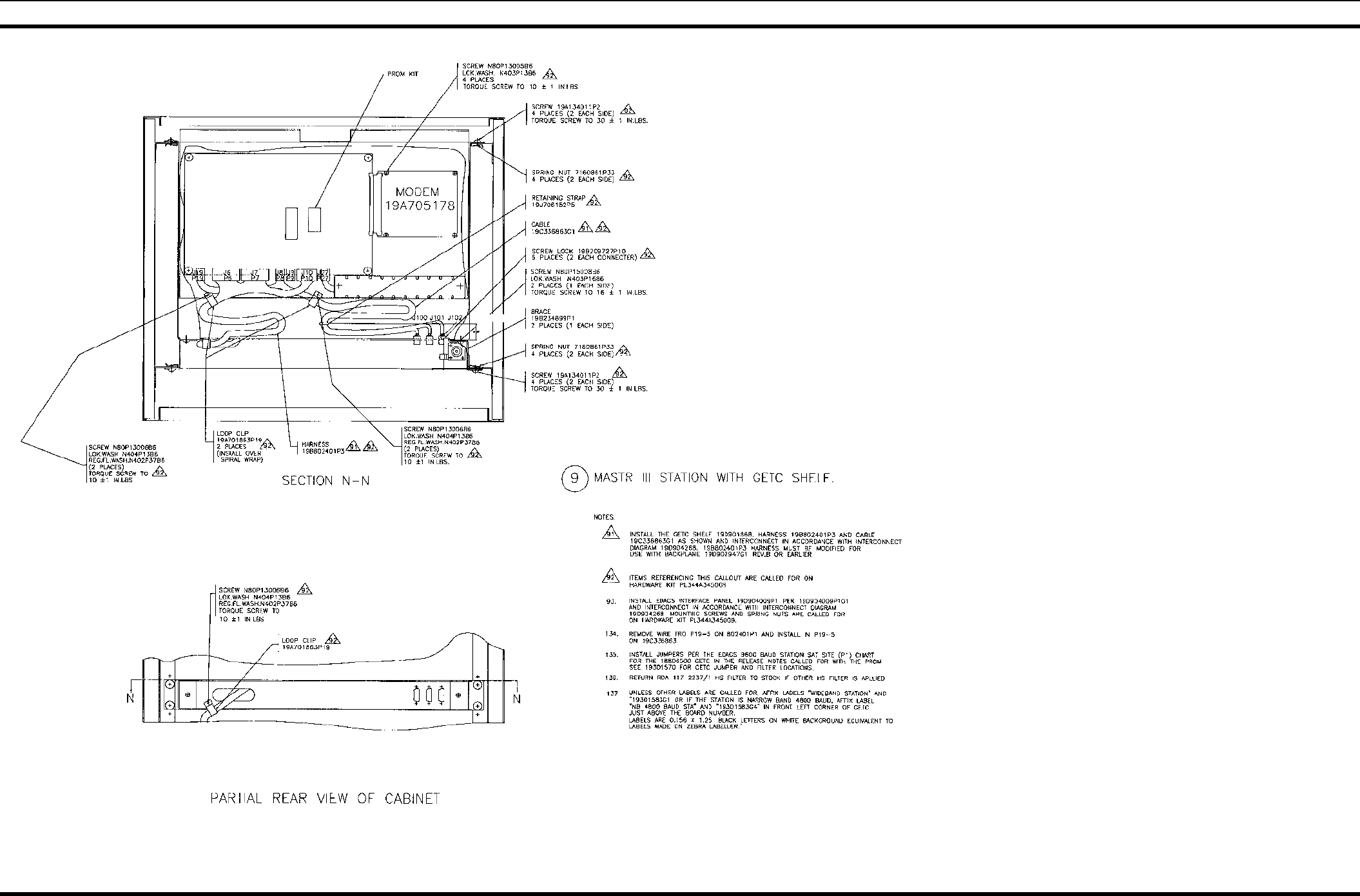
69" INDOOR CABINET WITH GETC SHELF
19D902845P9
(19D902845, Sh. 19, Rev. 12)
APPLICATION ASSEMBLY DIAGRAM
LBI-38775S 29
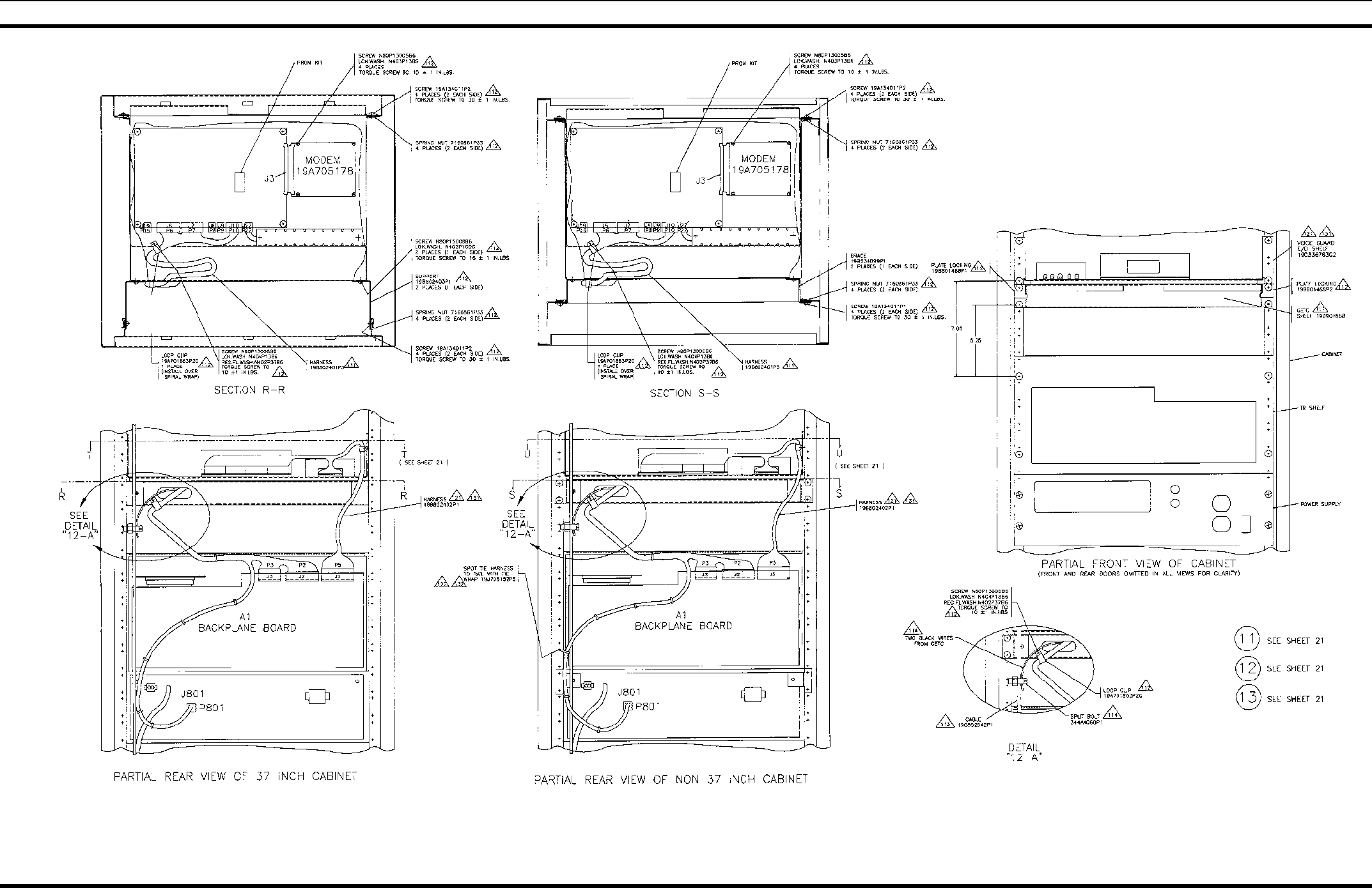
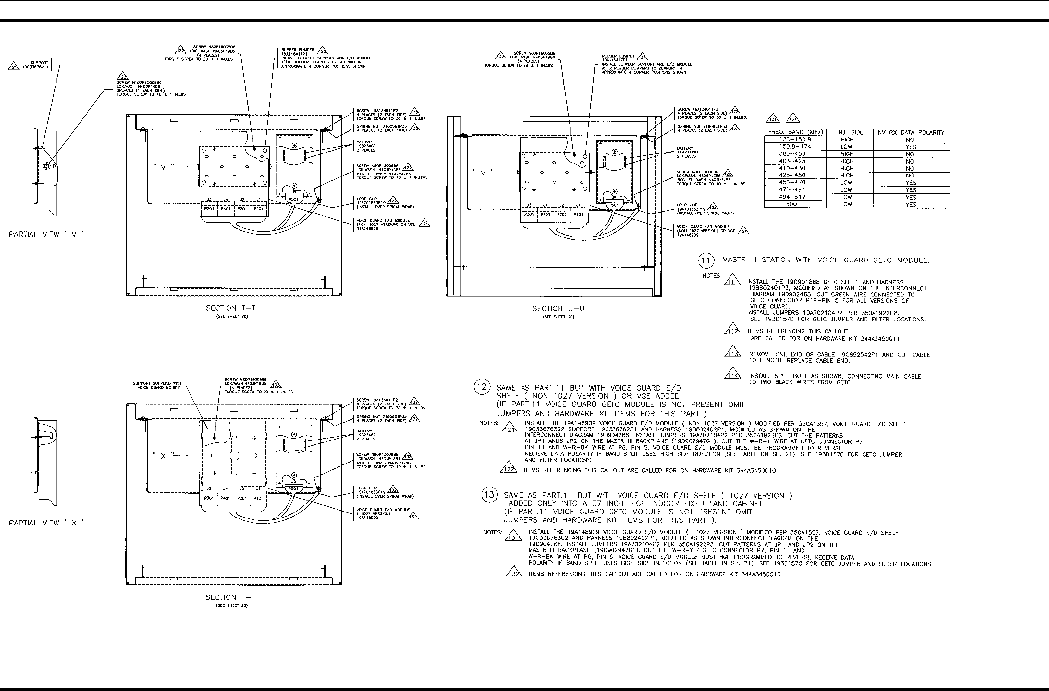
MASTR III BASE STATION WITH
VOICE GUARD GETC MODULE
19D902845P11-P13
(19D902845, Sh. 20, Rev. 11)
APPLICATION ASSEMBLY DIAGRAM
30 LBI-38775S
MASTR III BASE STATION WITH
VOICE GUARD GETC MODULE
19D902845P11-P13
(19D902845, Sh. 21, Rev. 4)
APPLICATION ASSEMBLY DIAGRAM
LBI-38775S 31
EDACS CABINET WITH ONE STATION
19D902845P15
(19D902845, Sh. 22, Rev. 12)
APPLICATION ASSEMBLY DIAGRAM
32 LBI-38775S
EDACS CABINET WITH MULTI-STATIONS
19D902845P16
(19D902845, Sh. 23, Rev. 11)
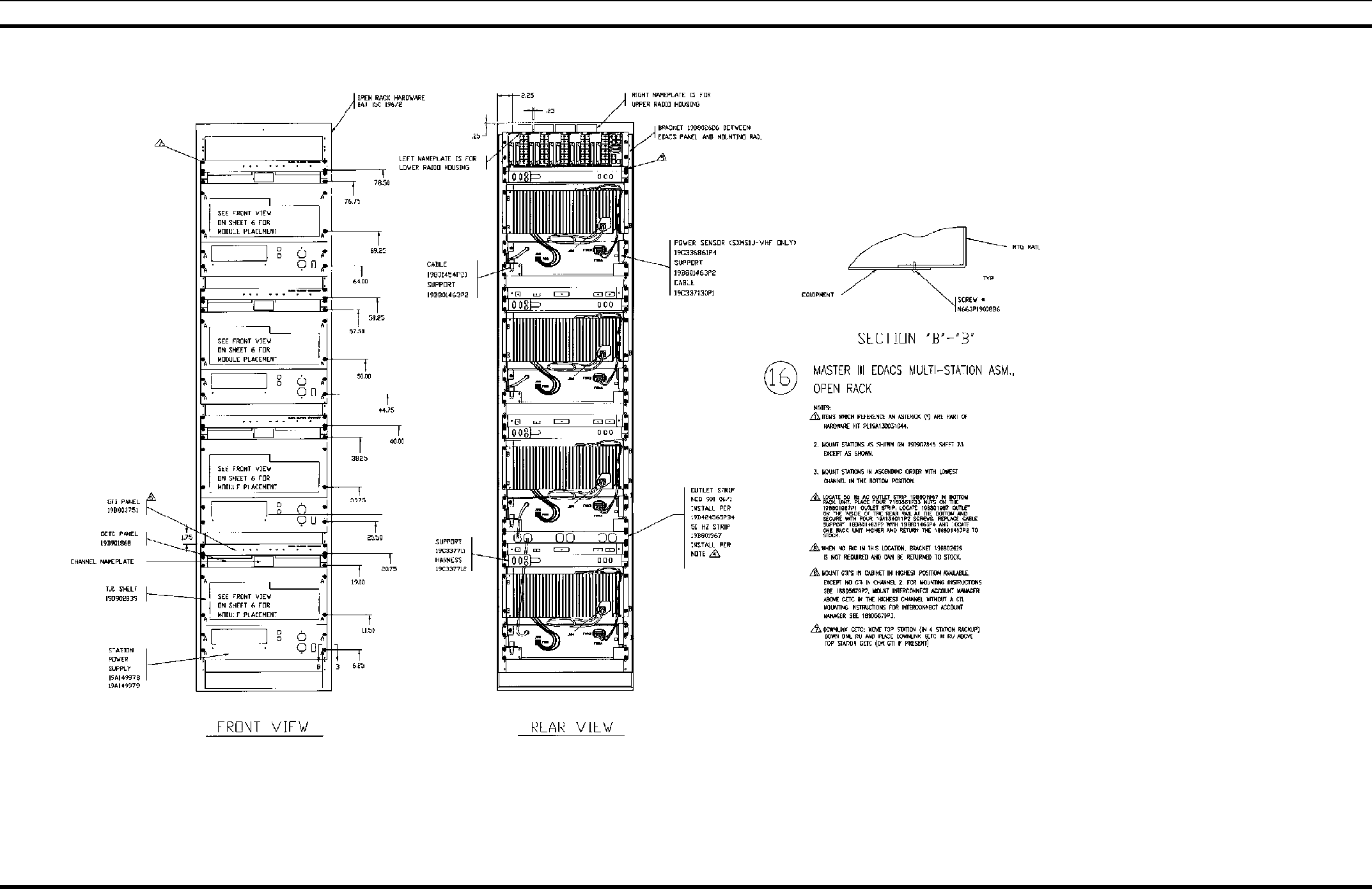
APPLICATION ASSEMBLY DIAGRAM
LBI-38775S 33
EDACS CABINET WITH MULTI-STATIONS
19D902845P16
(19D902845, Sh. 23A, Rev. 7)
APPLICATION ASSEMBLY DIAGRAM
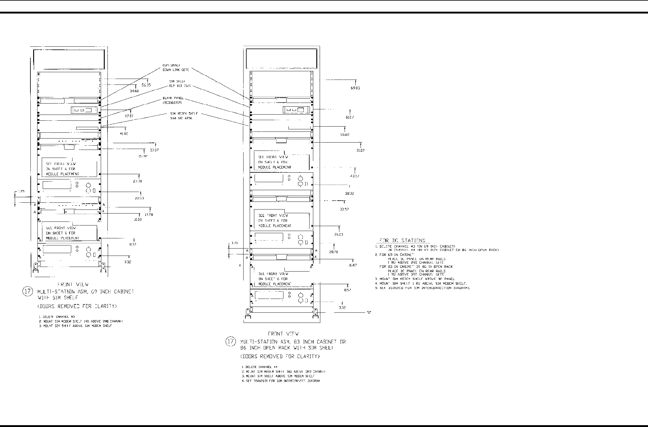
34 LBI-38775S
EDACS MULTI-STATION CABINET WITH SIM SHELF
19D902845P17
(19D902845, Sh. 23D, Rev. 2)
APPLICATION ASSEMBLY DIAGRAM
LBI-38775S 35
MULTI-STATION ASSEMBLY
19D902845P16
(19D902845, Sh. 24, Rev. 10)
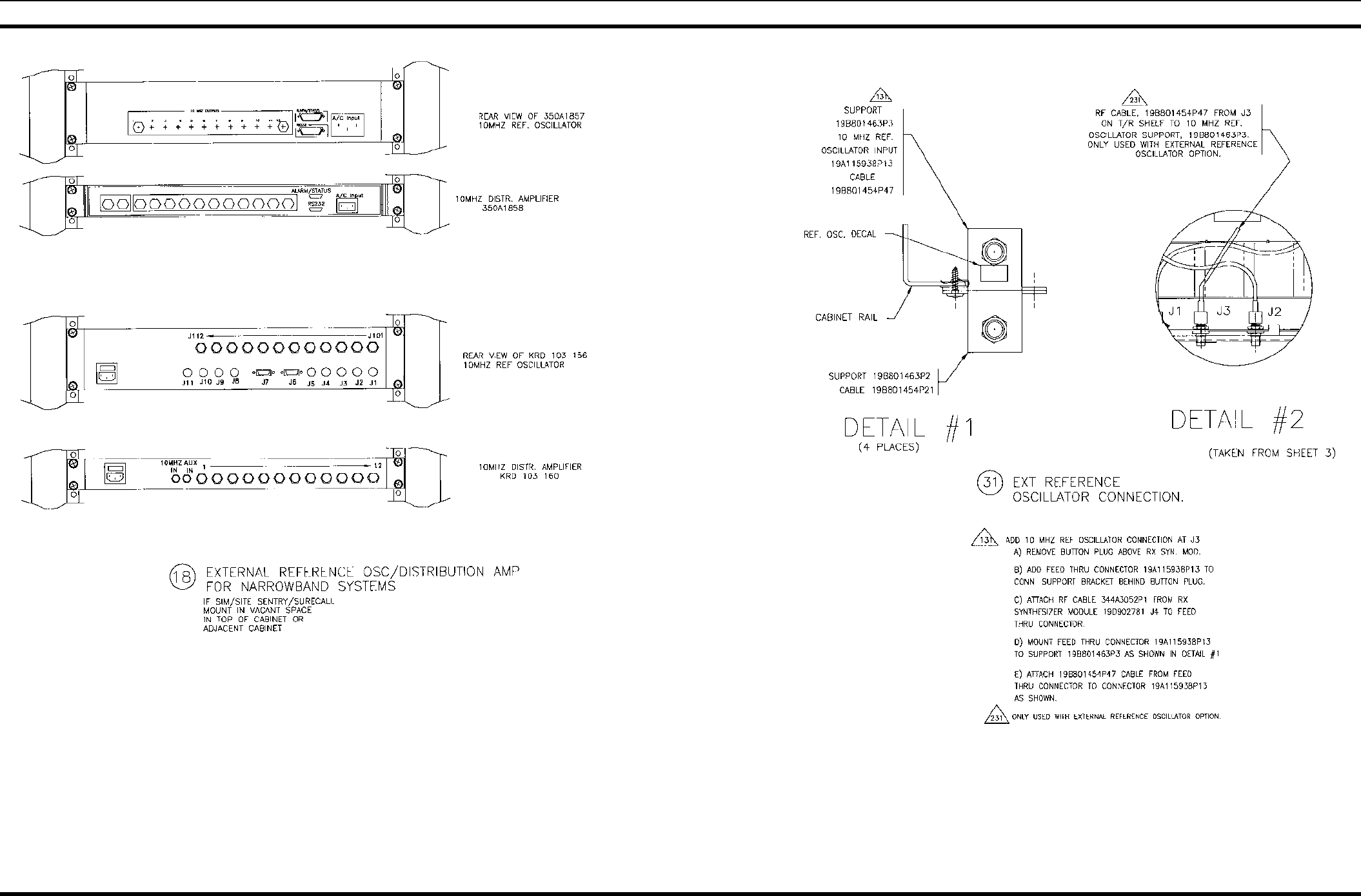
APPLICATION ASSEMBLY DIAGRAM
36 LBI-38775S
EXTERNAL REFFERENCE OSCILLATOR/DISTRIBUTION AMPLIFIER
FOR NARROW BAND SYSTEMS
19D902845P18 & P31
(19D902845, Sh. 24A, Rev. 4)
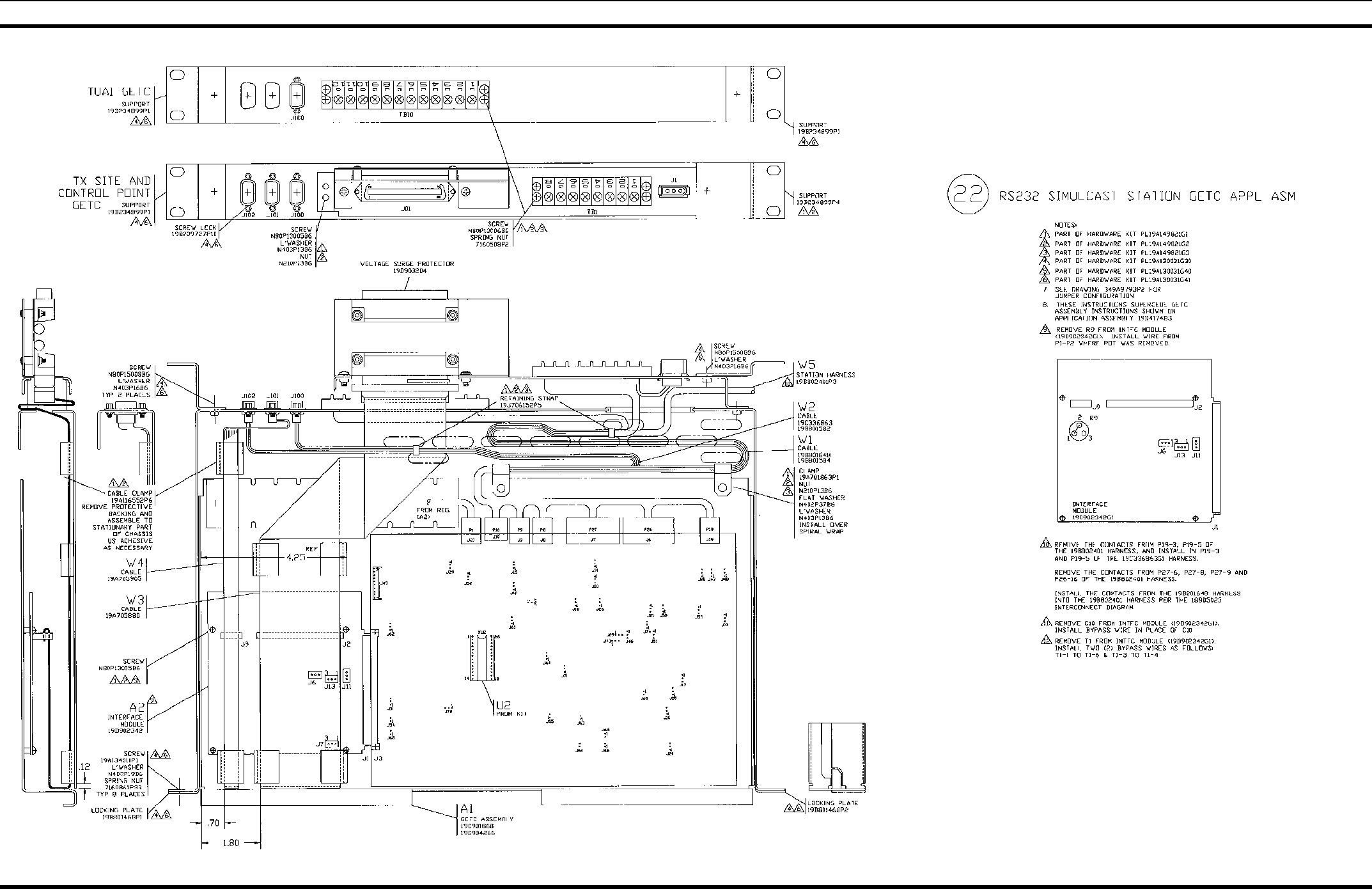
APPLICATION ASSEMBLY DIAGRAM
LBI-38775S 37
RS-232 SIMULCAST GETC
19D902845P22
(19D902845, Sh. 25, Rev. 10)
APPLICATION ASSEMBLY DIAGRAM
38 LBI-38775S
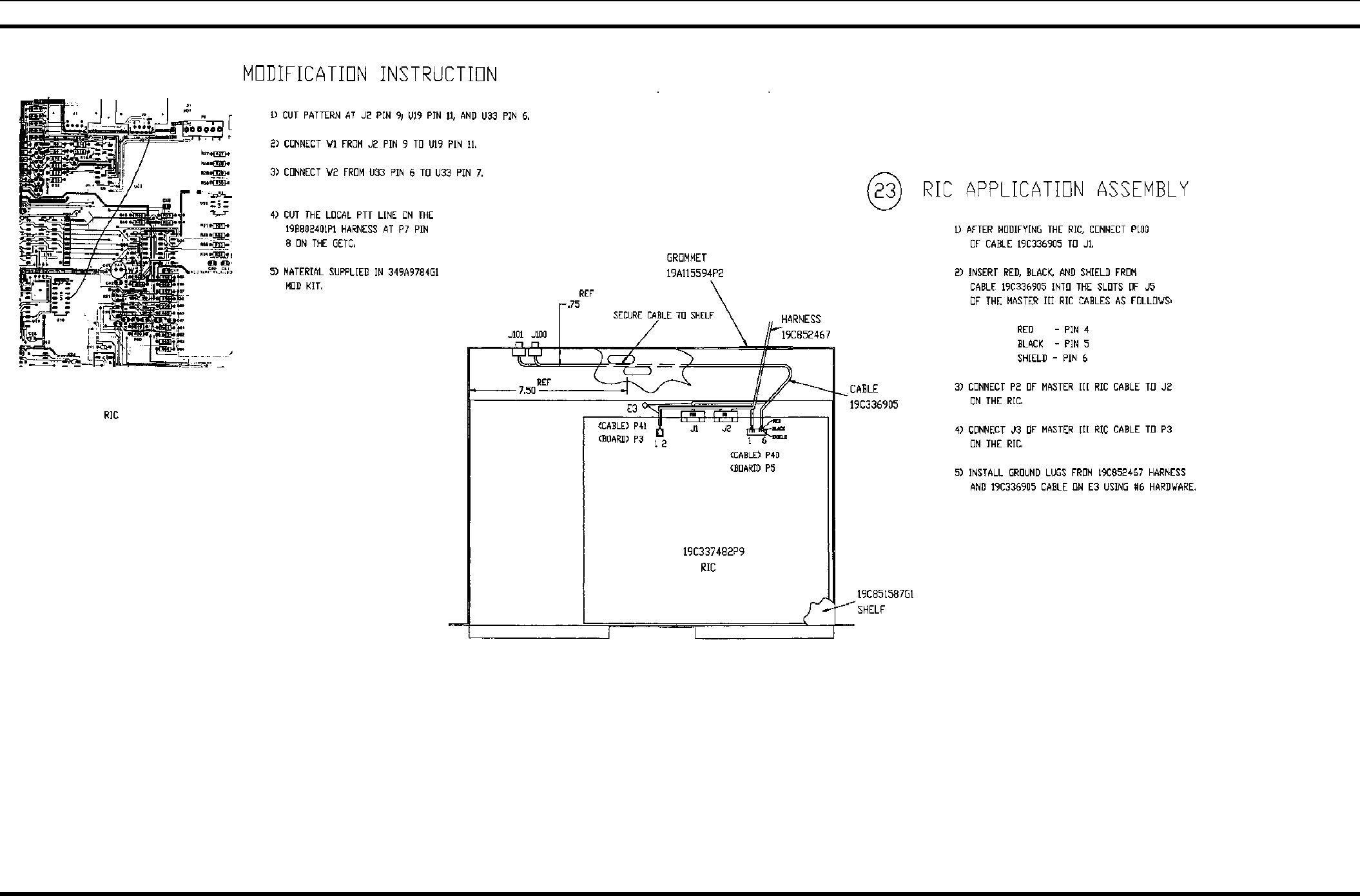
RIC EQUIPMENT
19D902845P23
(19D902845, Sh. 26, Rev. 6)
APPLICATION ASSEMBLY DIAGRAM
LBI-38775S 39
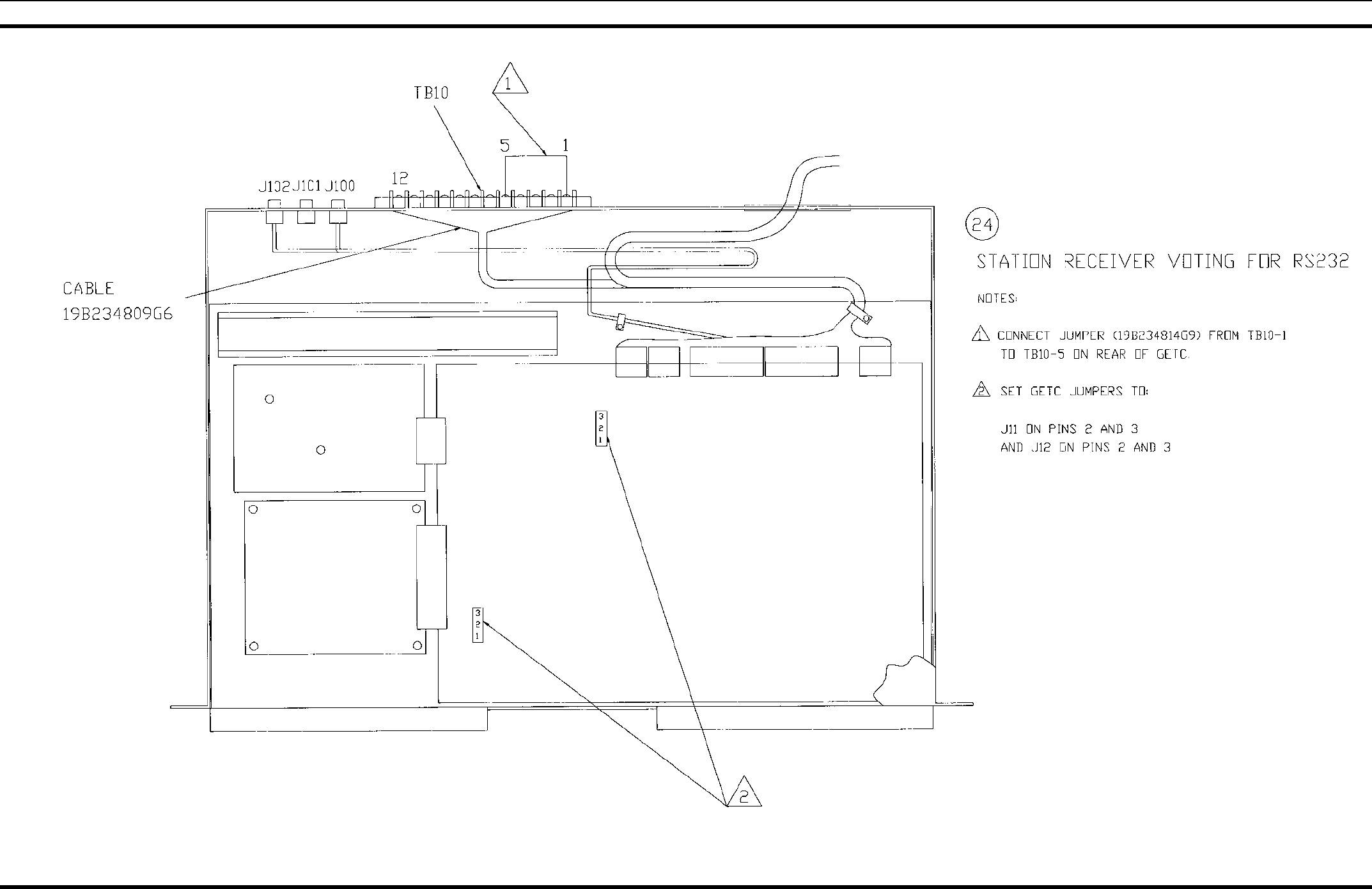
STATION RECEIVER VOTING FOR RS-232
19D902845P24
(19ED902845, Sh. 27, Rev. 4)
APPLICATION ASSEMBLY DIAGRAM
40 LBI-38775S
EDACS SIMULCAST STATION
19D902845P22 & P33
(19D902845, Sh. 28, Rev. 8)
APPLICATION ASSEMBLY DIAGRAM
LBI-38775S 41
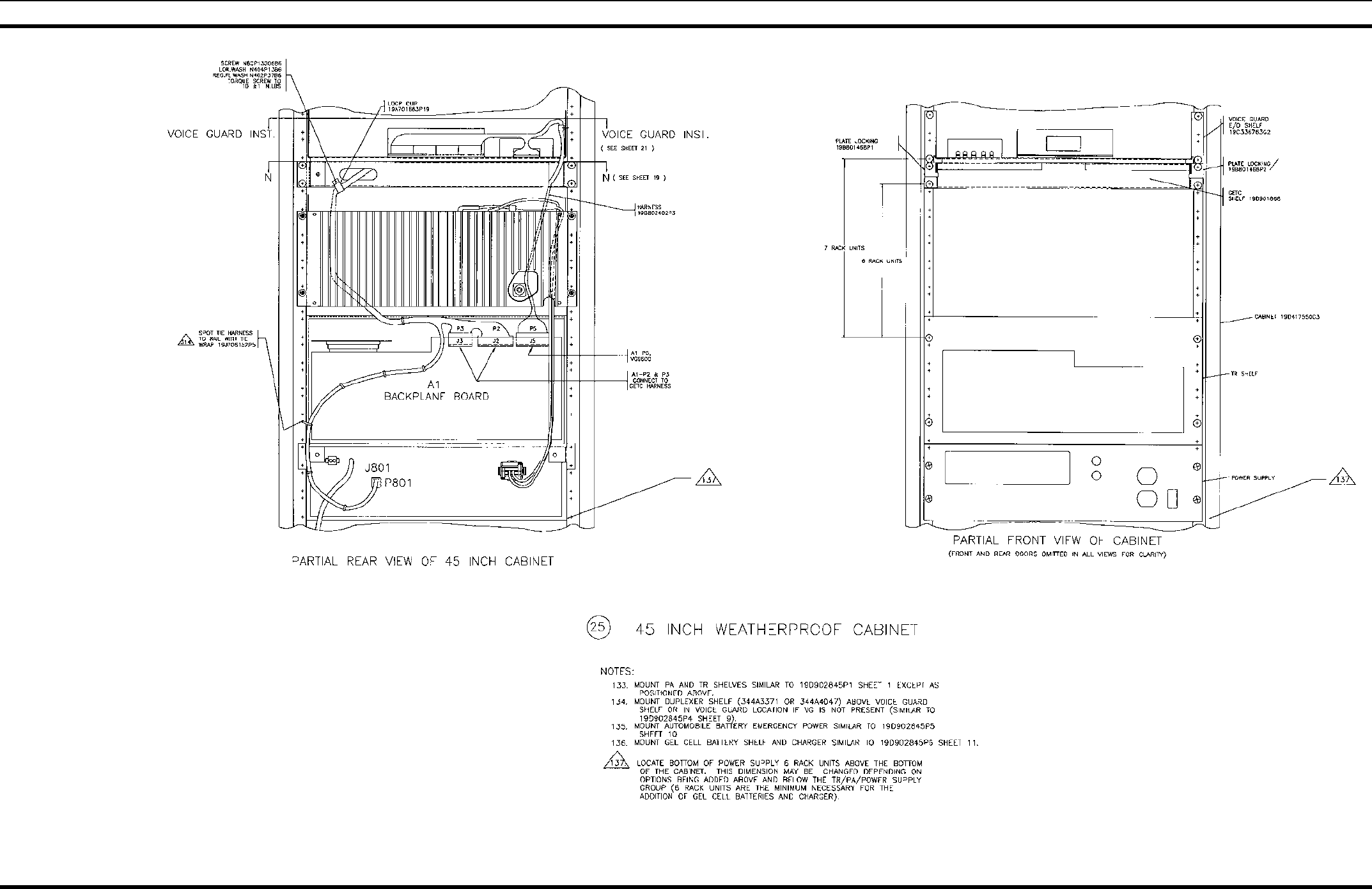
45" WEATHER PROOF CABINET
19D902845P25
(19D902845, Sh. 29, Rev. 3)
APPLICATION ASSEMBLY DIAGRAM
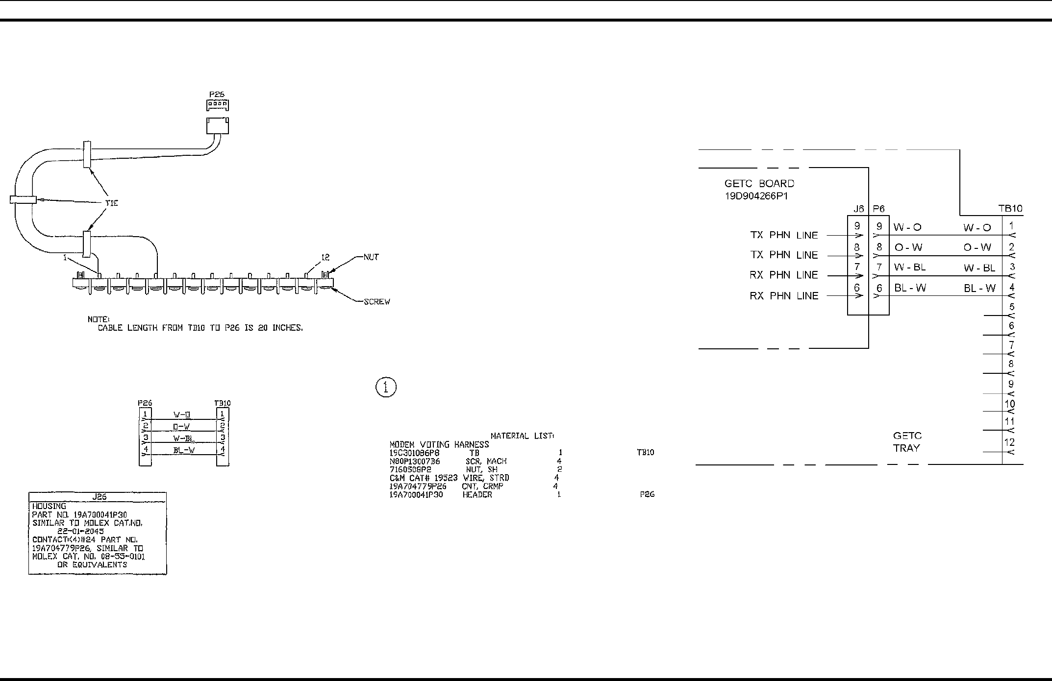
42 LBI-38775S
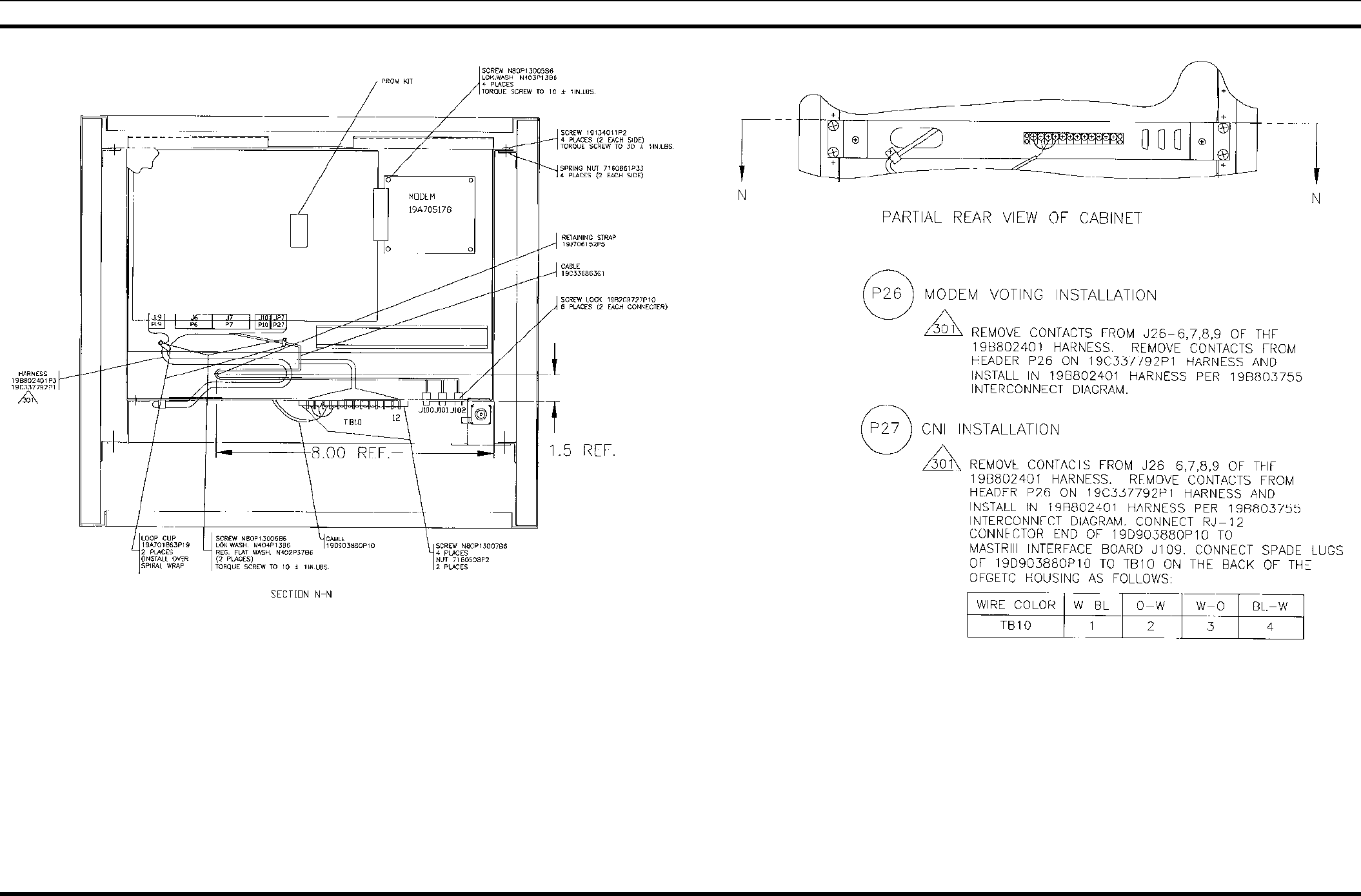
MODEM VOTING & CNI INSTALLATION
19D902845P26 & P27
(19D902845, Sh. 30, Rev.8)
APPLICATION ASSEMBLY DIAGRAM
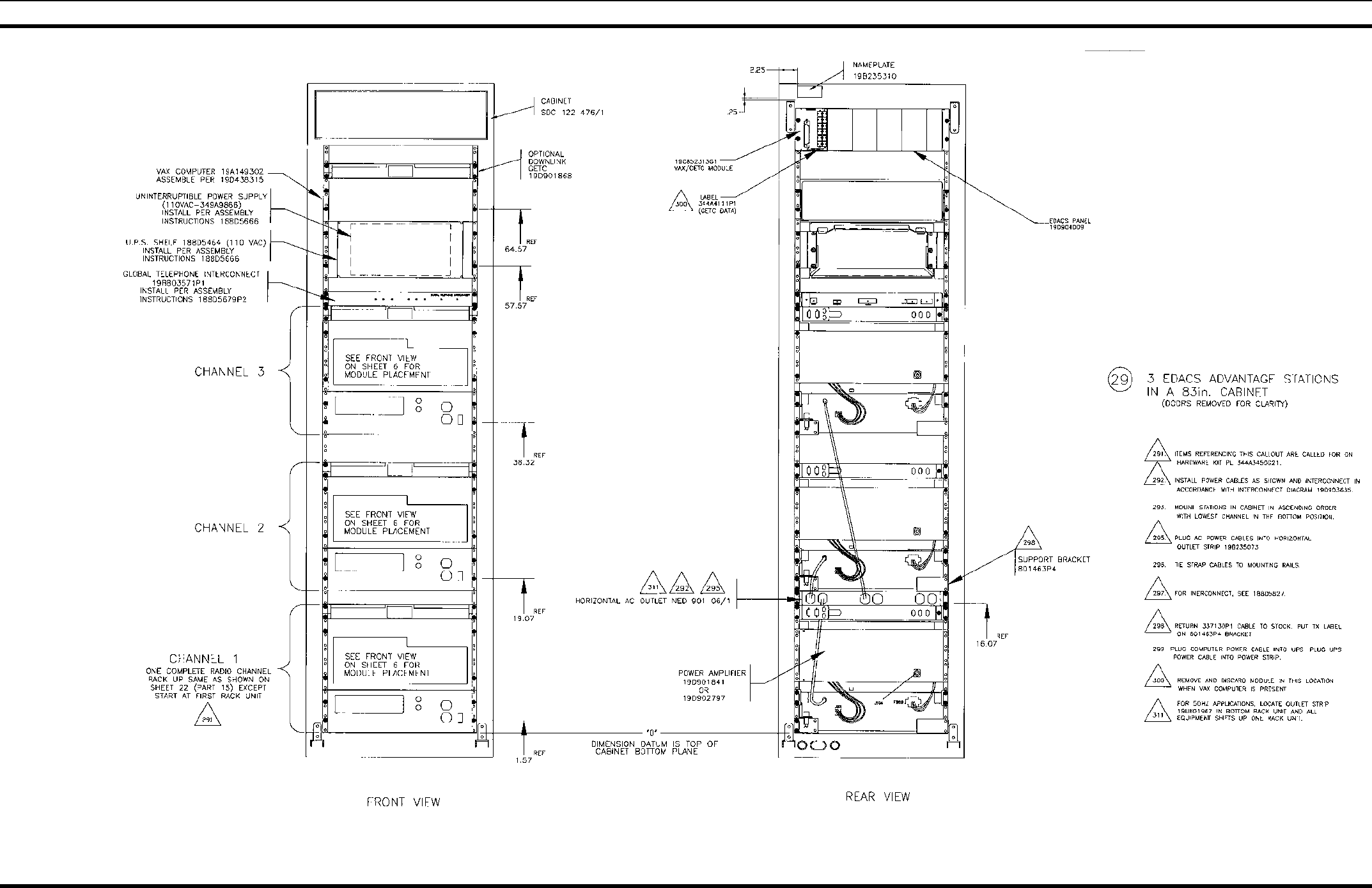
LBI-38775S 43
3 EDACS ADVANTAGE STATIONS
19D902845P29
(19D902845, Sh. 31, Rev. 7)
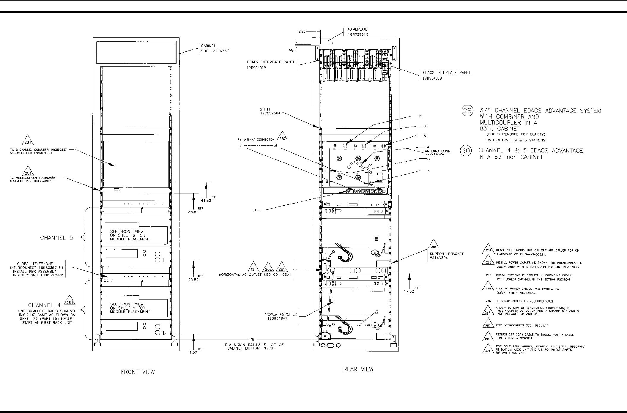
APPLICATION ASSEMBLY DIAGRAM
44 LBI-38775S
3/5 CHANNEL EDACS SYSTEM WITH COMBINER AND MULTICOUPLER CHANNEL 4 & 5
19D902845P28 & P30
(19D902845, Sh. 32, Rev. 6)
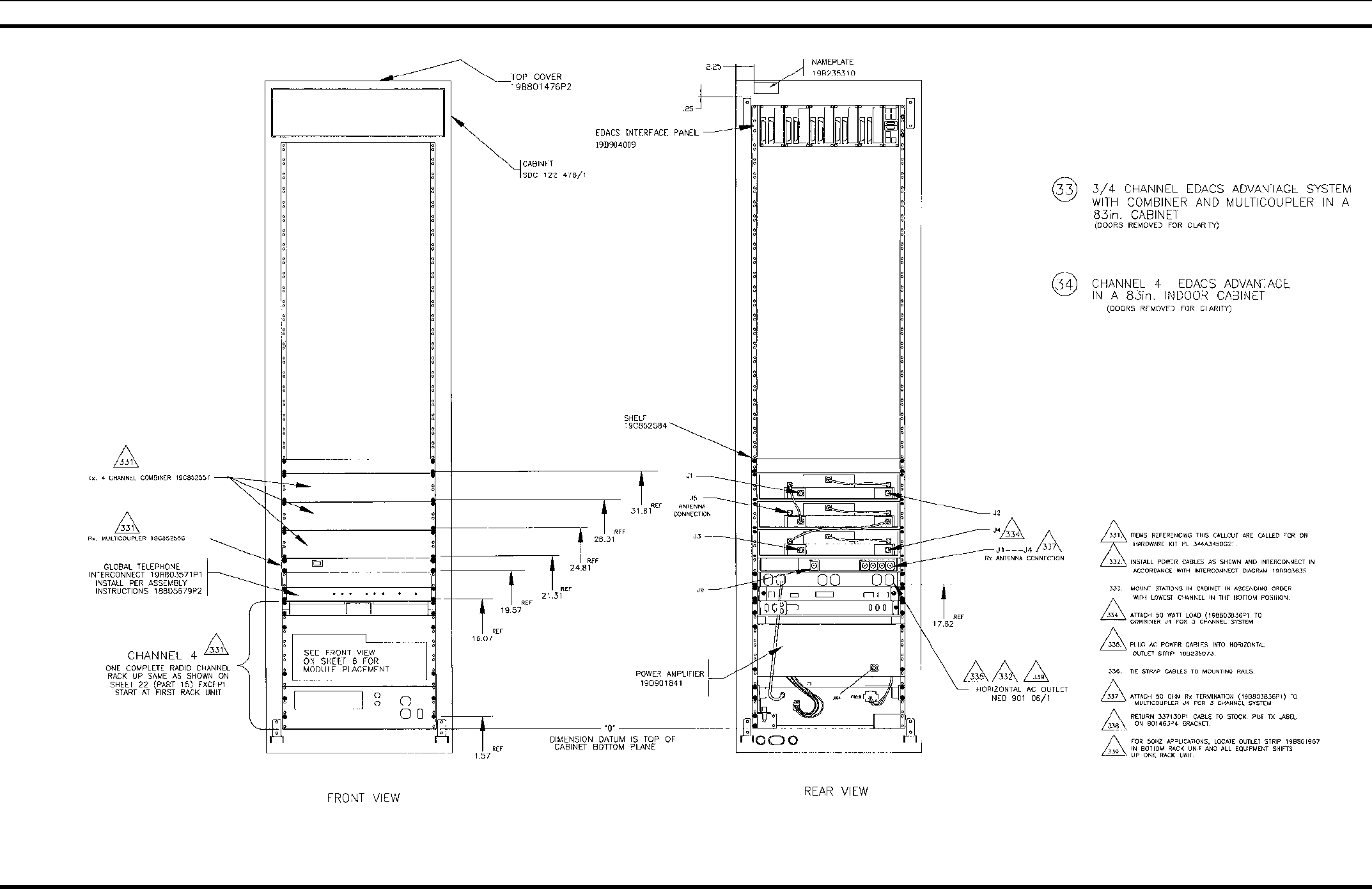
APPLICATION ASSEMBLY DIAGRAM
LBI-38775S 45
3/4 CHANNEL EDACS SYSTEM WITH COMBINER AND MULTICOUPLER
19D902845P33
(19D902845, Sh. 32A, Rev. 3)
APPLICATION ASSEMBLY DIAGRAM
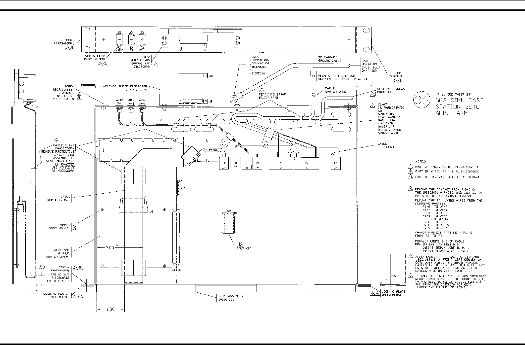
46 LBI-38775S
GPS SIMULCAST STATION GETC
19D902845P33
(19D902845, Sh. 33, Rev. 8)
HARNESS ASSEMBLY
LBI-38775S 47
HARNESS
19C337792P1
(19C337792, Sh. 1, Rev. 2)
(19B803755, Sh. 1, Rev. 3)
HARNESS ASSEMBLY
48 LBI-38775S
19B801454P16 & P17
(19B801454, Sh. 10, Rev. 27)
19B801454P17 & P18
(19B801454, Sh. 11, Rev. 27)
19B801454P19 & P20
(19B801454, Sh. 12, Rev. 27)
19B801454P24
(19B801454, Sh. 15, Rev. 27)
19B801454P43
(19B801454, Sh. 23, Rev. 27)
CONTROL CABLE ASSEMBLY (PART OF POWER AMPLIFIER)
19B801739P1
(19B801739, Sh 1, Rev. 2)
HARNESS ASSEMBLY
LBI-38775S 49
POWER CABLE (PART OF POWER AMPLIFIER)
19B801937P1
(19B801937, Sh. 1, Rev. 2)
19B235871P1
(19B237871, Sh. 1, Rev. 2)
344A3052P1
(344A3052, Sh. 1, Rev. 2)
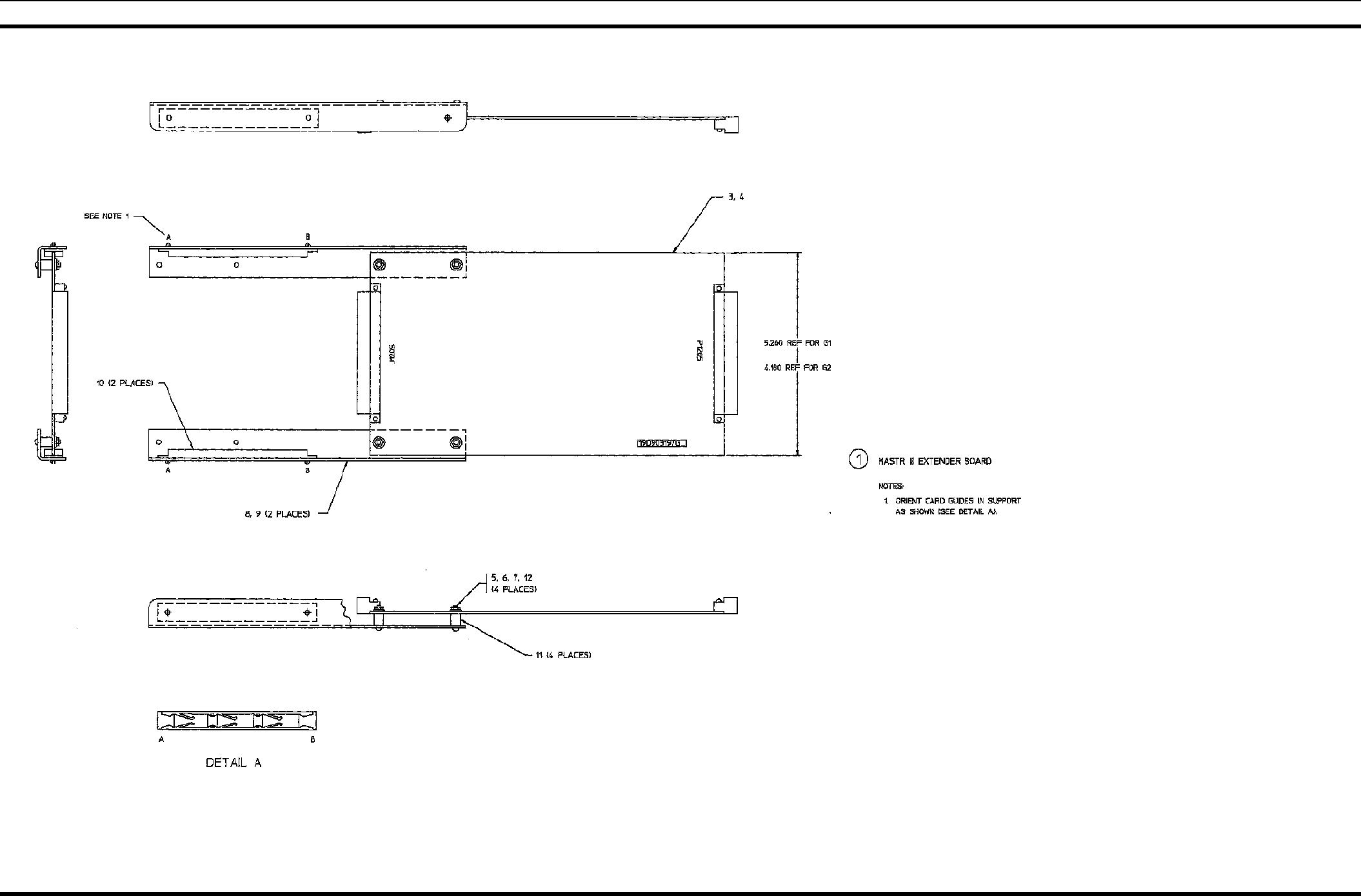
EXTENDER BOARDS
50 LBI-38775S
CONTROL EXTENDER BOARD 188D5338G1
RF EXTENDER BOARD 188D5338G2
(188D5338, Sh. 1, Rev. 2)
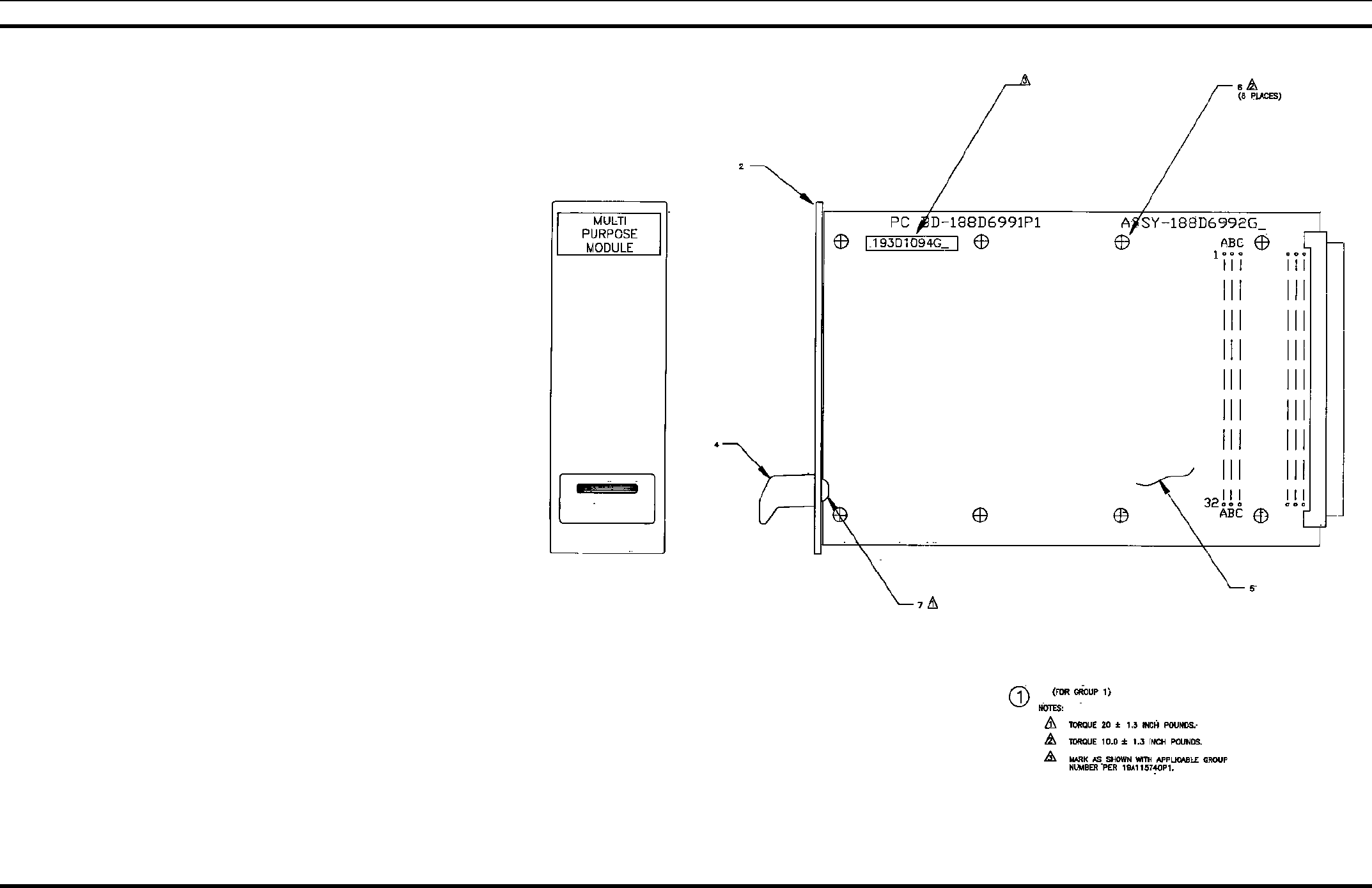
PARTS LISTE
LBI-38775S 51
MULTI PURPOSE MODULE 193D1094G1
(193D1094, Sh. 1, Rev.0)
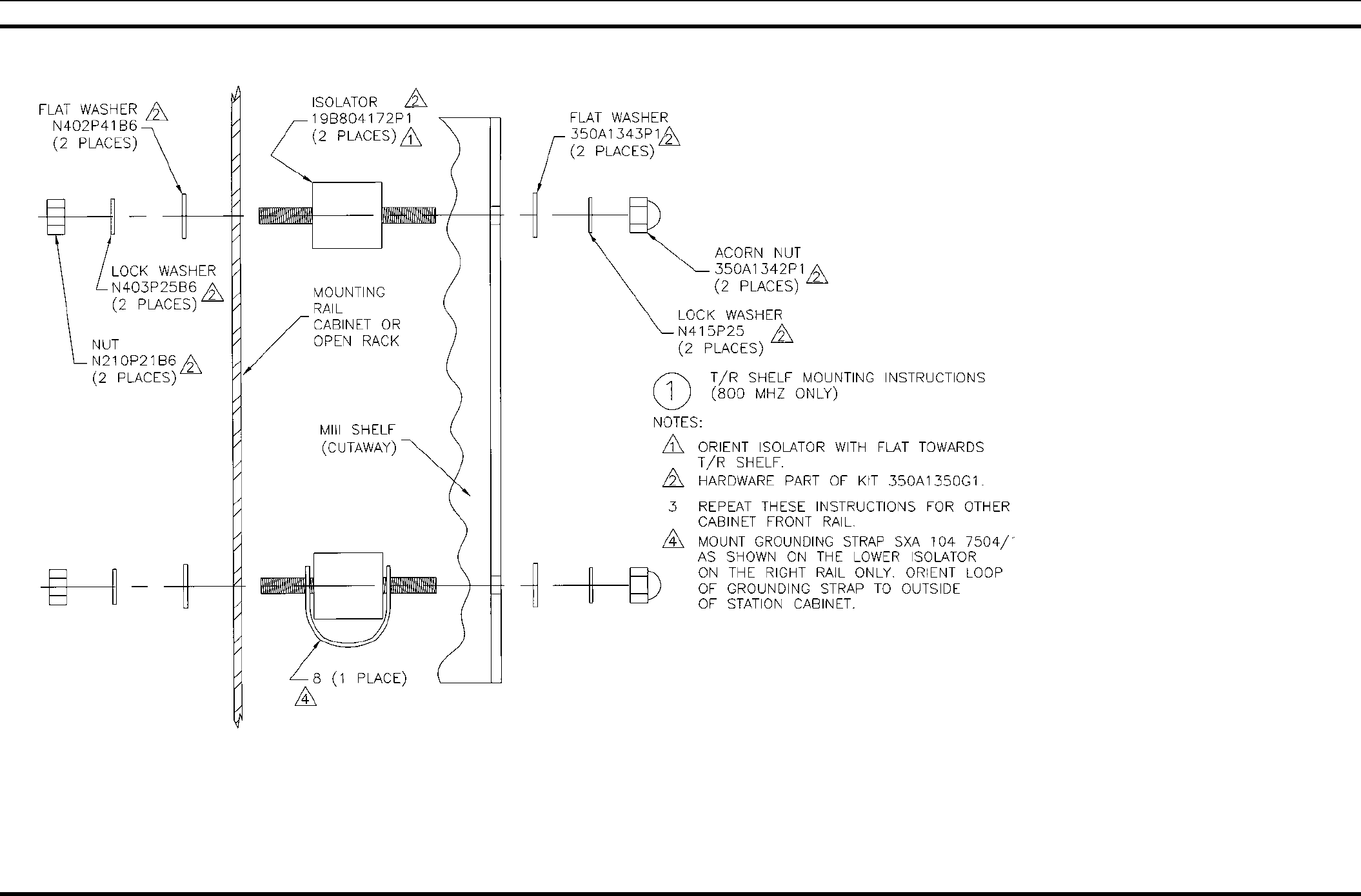
GROUNDING STRAP INSTALLATION INSTRUCTIONS
52 LBI-38775S
ISOLATOR KIT 350A130G1
The MASTR III 800 MHz T/R shelf is mounted in the station cabinet using Isolator Kit 350A1350G1, which provides
rubber isolators, needed at 800 MHz to dampen vibrations. This kit also provides grounding strap SXA 104 7504/1.
This grounding strap is used with the lower isolator on the right rail only. As shown above, this strap (Item 8) slips
over each end of the isolator studs with the loop oriented toward the outside cabinet wall.
GROUNDING STRAP INSTALLATION INSTRUCTIONS
(19B803970, Rev. 3)

PARTS LISTE
LBI-38775S 53
PARTS LIST
MASTR III STATION
Issue 4
SYMBOL PART NO. DESCRIPTION
- - - - - - 37" CABINET - - - - - -
19D902838P1 37-inch Cabinet.
19C852074P1 Equipment support rail (left side).
19C852074P2 Equipment support rail (right side).
344A3450G1 Hardware Kit.
344A3450G2 Hardware Kit.
19D902422P4 Rear Door.
19D902422P4 Front Door.
19J706152P5 Tie Strap.
5491682P4 Key, sim to Yale & Towne #BF-10A
5490407P29 Grommet.
- - - - - - - - - 69" CABINET - - - - - - -
19D417358G3 69-inch Cabinet.
19D417623G4 Grill, Label.
19A130031G12 Hardware Kit.
19B226318P2 Plate.
19B801476P1 Cover.
19B801476P2 Cover.
19B209539P1 Lock, rim.
19B209539P2 Lock, rim.
19B209539P3 Key, lock, rim.
344A3450G21 Hardware Kit.
5490407P29 Grommet.
19C320895G12 Fan 120 VAC.
19C320895G15 Fan 230 VAC.
- - - - - - 83" CABINET - - - - - - -
19D902663G1 83-inch Cabinet.
19C337428G1 Door.
19C337428G2 Door.
19B801476P1 Cover.
19B801476P2 Cover.
19B209539P2 Lock, rim.
19B209239P2 Lock, rim.
19B209539P3 Key, lock, rim.
19B226318P2 Plate.
344A2450P21 Hardware Kit.
19C320895G12 Fan 120 VAC.
19C320895G15 Fan 230 VAC.
- - - - - - CABLES - - - - - - -
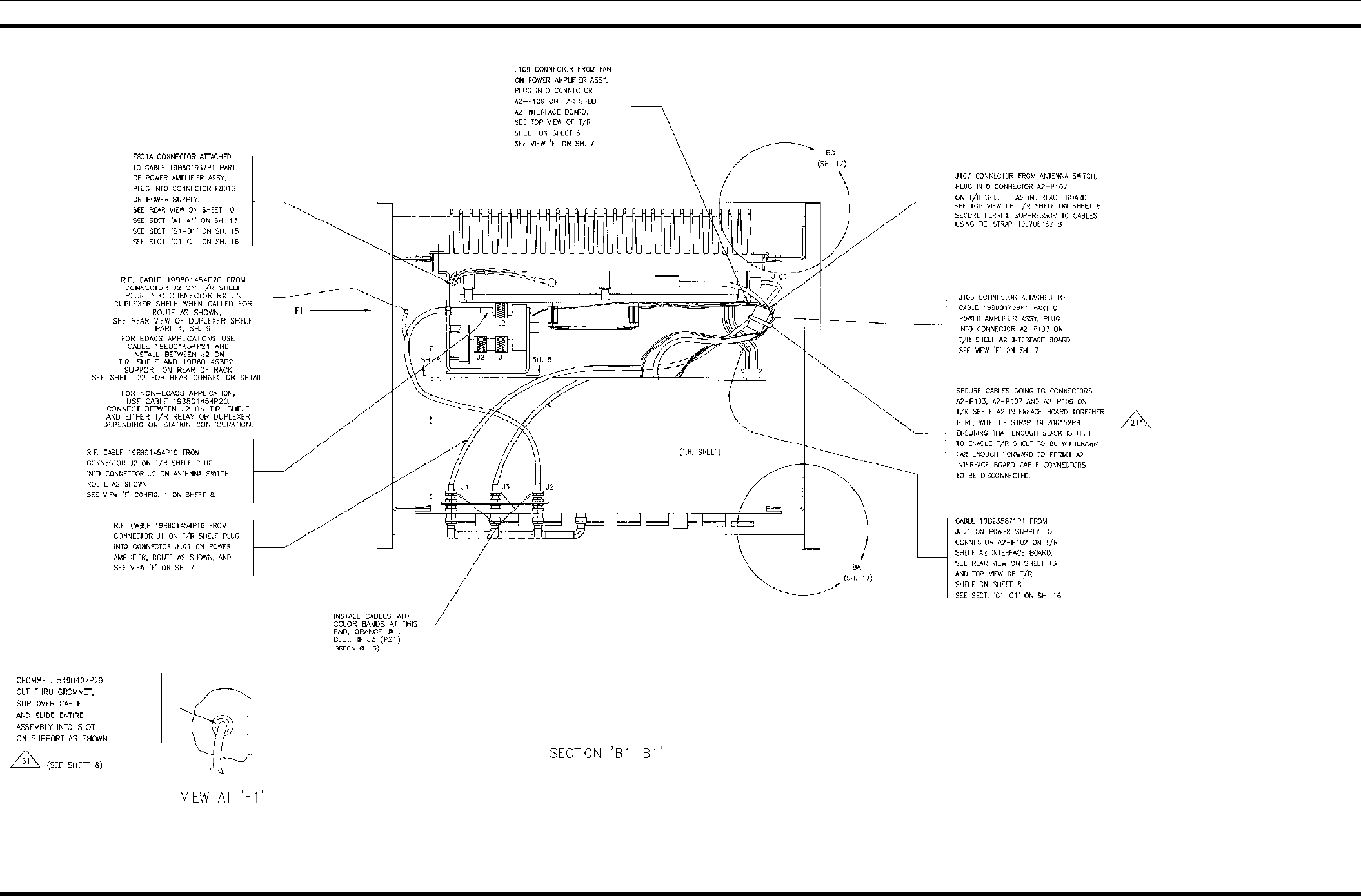
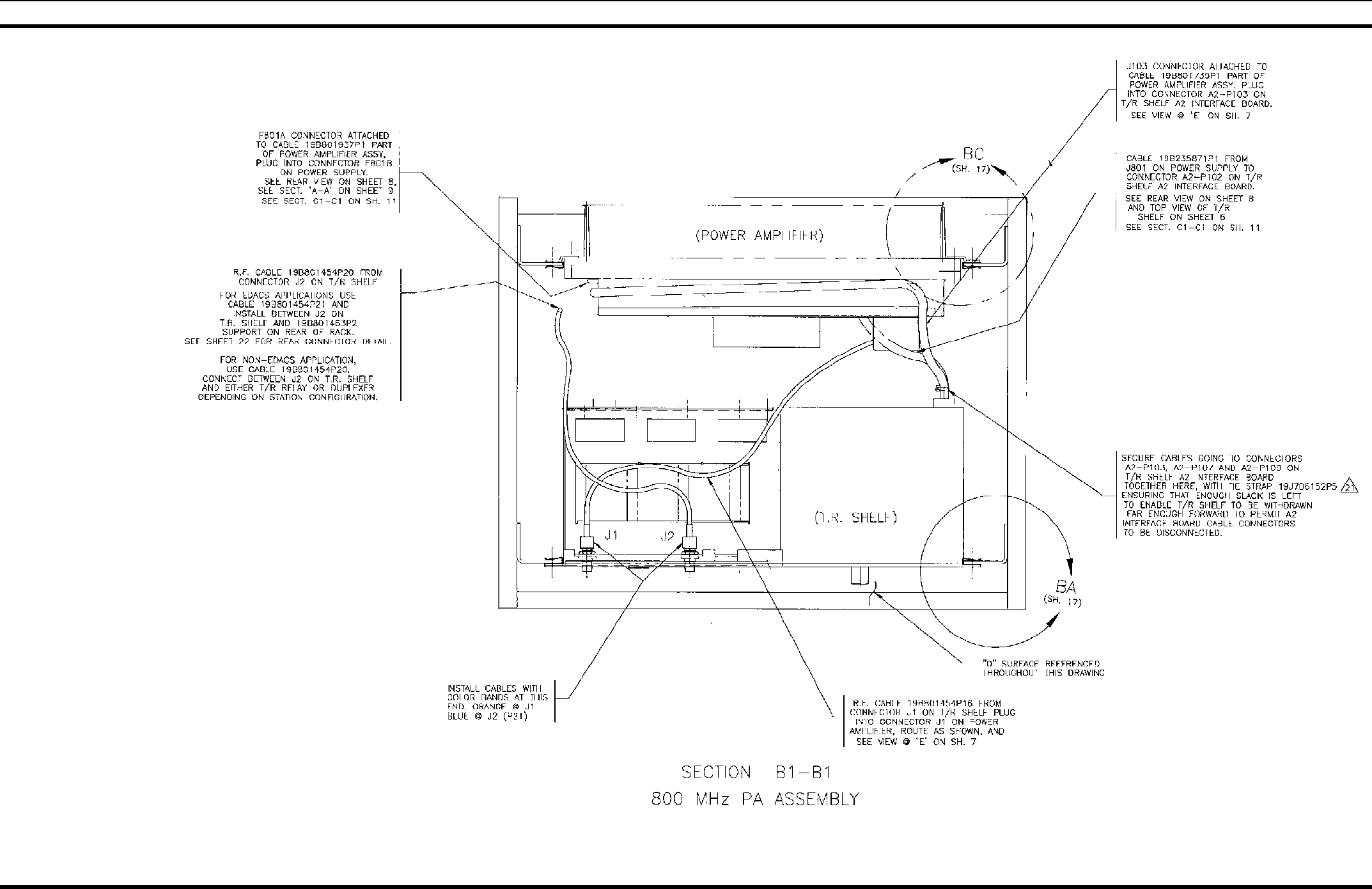
19B235871P1 Power Cable: Station Power Supply (J801) to T/R
Shelf (A2-P102).
19B801454P17 RF Cable: Low Pass Filter (J1) to Power Amplifier
(J104). Replaced by 19B801454P43.
19B801454P20 RF Cable: T/R Shelf (J2) to Duplexer Shelf (J2)
(Used when Duplexer is installed).
19B801454P19 RF Cable: T/R Shelf (J2) to Antenna Switch (J2).
19B801454P16 RF Cable: T/R Shelf (J1) to Power Amplifier (J101).
19B801454P43 RF Cable: Low Pass Filter (J1) to Power Amplifier
(J104).
*COMPONENTS ADDED, DELETED OR CHANGED BY PRODUCTION CHANGES

M/A-COM Wireless Systems
3315 Old Forest Road
Lynchburg, Virginia 24501
(Outside USA, 434-385-2400) Toll Free 800-528-7711
www.macom-wireless.com Printed in U.S.A.