HARRIS TR-0037-E EDACS D3100 800 MHz Mobile Data Modem User Manual TYPE CERTIFICATION REPORT
HARRIS CORPORATION EDACS D3100 800 MHz Mobile Data Modem TYPE CERTIFICATION REPORT
HARRIS >
Manual

Rhein Tech Laboratories Client: M/A COM, Inc.
360 Herndon Parkway Model: EDACS D3100 800 MHz Mobile Data Modem
Suite 1400 FCC ID: OWDTR-0037-E
Herndon, VA 20170 Standards: FCC Part 90/IC RSS-119
http://www.rheintech.com Report #: 2004178
36 of 44
APPENDIX K: MANUAL
Please refer to the following pages.

Installation and Operator’s Manual
MM21134
December-04
EDACS® D3100
RF Modem

2
REVISIO
N DATE REASON FOR CHANGE
- December 2004 Initial Release.
M/A-COM Technical Publications would particularly appreciate feedback on
any errors found in this document and suggestions on how the document
could be improved. Submit your comments and suggestions to:
Wireless Systems Business Unit
M/A-COM, Inc.
Technical Publications
221 Jefferson Ridge Parkway
Lynchburg, VA 24501
or fax your comments to: (434) 455-6851
or e-mail us at: techpubs@tycoelectronics.com
CREDITS
EDACS is a registered trademark and Failsoft and ProGrammer are
trademarks of M/A-COM, Inc.
Torx is a registered trademark of Camcar Innovative Solutions.
All other brand and product names are trademarks, registered trademarks or
service marks of their respective holders.
NOTICE!
This manual covers M/A-COM products manufactured and sold by
M/A-COM, Inc.
Repairs to this equipment should be made only by an authorized service
technician or facility designated by the supplier. Any repairs, alterations, or
substitution of recommended parts made by the user to this equipment not
approved by the manufacturer could void the user’s authority to operate the
equipment in addition to the manufacturer’s warranty.
The software contained in this device is copyrighted by M/A-COM, Inc.
Unpublished rights are reserved under the copyright laws of the United States.
This manual is published by M/A-COM, Inc., without any warranty. Improvements and changes
to this manual necessitated by typographical errors, inaccuracies of current information, or
improvements to programs and/or equipment, may be made by M/A-COM, Inc., at any time and
without notice. Such changes will be incorporated into new editions of this manual. No part of
this manual may be reproduced or transmitted in any form or by any means, electronic or
mechanical, including photocopying and recording, for any purpose, without the express written
permission of M/A-COM, Inc.
Copyright© 2004 M/A-COM, Inc. All rights reserved.

3
TABLE OF CONTENTS
Page
1. RF ENERGY EXPOSURE INFORMATION............................4
1.1 RF ENERGY EXPOSURE AWARENESS, CONTROL
INFORMATION, AND OPERATION INSTRUCTIONS
FOR FCC OCCUPATIONAL USE REQUIREMENTS .....4
1.1.1 Federal Communications Commission Regulations..5
1.2 COMPLIANCE WITH RF EXPOSURE STANDARDS....5
1.2.1 Mobile Antennas .......................................................6
1.2.2 Approved Accessories...............................................6
1.2.3 Contact Information...................................................7
2. SAFETY INFORMATION..........................................................8
2.1 COMMON HAZARDS .......................................................8
3. INTRODUCTION ........................................................................9
4. DESCRIPTION...........................................................................10
4.1 DATA CONNECTOR FUNCTIONS................................11
5. OPTIONS AND ACCESSORIES..............................................12
5.1 ADAPTER CABLE, CA103067V1...................................12
6. INSTALLATION........................................................................14
6.1 UNPACK AND CHECK THE EQUIPMENT ..................14
6.2 PLAN THE INSTALLATION ..........................................14
6.3 INSTALL D3100 RF MODEM.........................................15
6.4 D3100 DIMENSIONS.......................................................16
7. WARRANTY ..............................................................................17
1. RF ENERGY EXPOSURE INFORMATION
1.1 RF ENERGY EXPOSURE AWARENESS,
CONTROL INFORMATION, AND OPERATION
INSTRUCTIONS FOR FCC OCCUPATIONAL
USE REQUIREMENTS
Before using your mobile two-way radio, read this important RF energy
awareness and control information and operational instructions to
ensure compliance with the FCC’s RF exposure guidelines.
NOTE
This radio is intended for use in occupational/controlled
conditions, where users have full knowledge of their
exposure and can exercise control over their exposure to
meet FCC limits. This radio device is NOT authorized for
general population, consumer, or any other use.
CAUTION
Changes or modifications not expressly approved by M/A-
COM, Inc. could void the user's authority to operate the
equipment.
This two-way radio uses electromagnetic energy in the radio frequency (RF)
spectrum to provide communications between two or more users over a
distance. It uses RF energy or radio waves to send and receive calls. RF
energy is one form of electromagnetic energy. Other forms include, but are
not limited to, electric power, sunlight, and x-rays. RF energy, however,
should not be confused with these other forms of electromagnetic energy,
which, when used improperly, can cause biological damage. Very high levels
of x-rays, for example, can damage tissues and genetic material.
Experts in science, engineering, medicine, health, and industry work with
organizations to develop standards for exposure to RF energy. These
standards provide recommended levels of RF exposure for both workers and
the general public. These recommended RF exposure levels include
substantial margins of protection. All two-way radios marketed in North
America are designed, manufactured, and tested to ensure they meet
government established RF exposure levels. In addition, manufacturers also
recommend specific operating instructions to users of two-way radios. These
instructions are important because they inform users about RF energy
4

5
exposure and provide simple procedures on how to control it. Please refer to
the following websites for more information on what RF energy exposure is
and how to control your exposure to assure compliance with established RF
exposure limits.
http://www.fcc.gov/oet/rfsafety/rf-faqs.html
http://www.osha.gov./SLTC/radiofrequencyradiation/index.html
1.1.1 Federal Communications Commission
Regulations
Your M/A-COM, Inc. EDACS D3100 RF Modem is designed and tested to
comply with the FCC RF energy exposure limits for mobile two-way radios
before it can be marketed in the United States. When two-way radios are
used as a consequence of employment, the FCC requires users to be fully
aware of and able to control their exposure to meet occupational
requirements. Exposure awareness can be facilitated by the use of a label
directing users to specific user awareness information. Your M/A-COM, Inc.
EDACS D3100 RF Modem has an RF exposure product label. Also, your
D3100 Installation and Operator’s Manual includes information and operating
instructions required to control your RF exposure and to satisfy compliance
requirements.
1.2 COMPLIANCE WITH RF EXPOSURE
STANDARDS
Your M/A-COM, Inc. EDACS D3100 RF Modem is designed and tested to
comply with a number of national and international standards and guidelines
(listed below) regarding human exposure to RF electromagnetic energy. This
radio complies with the IEEE and ICNIRP exposure limits for
occupational/controlled RF exposure environment at duty factors of up to
60% talk-40% listen and is authorized by the FCC for occupational use. In
terms of measuring RF energy for compliance with the FCC exposure
guidelines, your radio antenna radiates measurable RF energy only while it is
transmitting (talking), not when it is receiving (listening) or in standby mode.
Your M/A-COM, Inc. EDACS D3100 RF Modem complies with the
following RF energy exposure standards and guidelines:
• United States Federal Communications Commission (FCC), Code of
Federal Regulations; 47 CFR §§ 2 sub-part J.
• American National Standards Institute (ANSI)/Institute of Electrical
and Electronic Engineers (IEEE) C95.1-1992.
• Institute of Electrical and Electronic Engineers (IEEE) C95.1-1999.
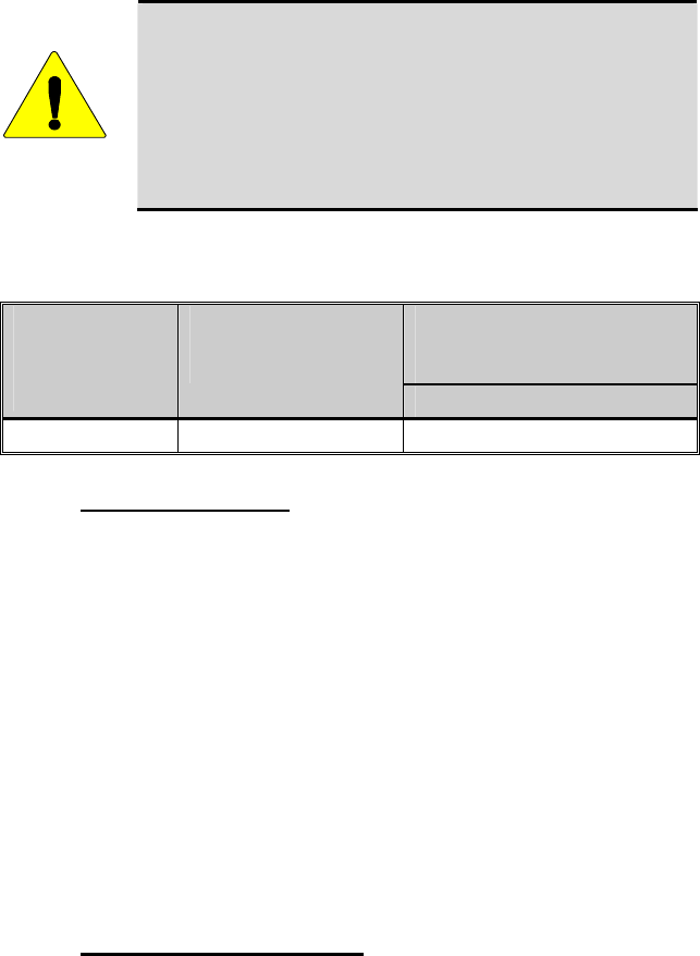
CAUTION
Table 1-1 lists the recommended minimum lateral distance
from the AV102800V1 mobile antenna that must be
provided for unaware bystanders in an uncontrolled
environment, when the D3100 is transmitting at three watts.
Transmit only when unaware bystanders are at least the
uncontrolled recommended minimum lateral distance away
from the transmitting antenna.
Table 1-1: Rated Power and Recommended Minimum Lateral Distance
RECOMMENDED MINIMUM
LATERAL DISTANCE FROM
TRANSMITTING ANTENNA
MOBILE RADIO
TX
FREQUENCY
RANGE
RATED POWER OF
VEHICLE-INSTALLED
D3100 RF MODEM
UNCONTROLLED
806-825 MHz 3.0 Watts 21 cm
1.2.1 Mobile Antennas
Install the radio’s antenna (refer to Table 5-1 for applicable antenna part
numbers) in the center of the vehicle’s roof. These mobile antenna
installation guidelines are limited to metal body motor vehicles or vehicles
with appropriate ground planes. The antenna installation should additionally
be in accordance with the following.
1. The requirements of the antenna manufacturer/supplier included with the
antenna.
2. The installation manual providing specific information of how to install
the antennas to facilitate recommended operating distances to all
potentially exposed persons.
Use only the M/A-COM approved/supplied antenna(s) or approved
replacement antenna. Unauthorized antennas, modifications, or attachments
could damage the radio and may violate FCC regulations.
1.2.2 Approved Accessories
This radio has been tested and meets the FCC RF guidelines when used with
the M/A-COM accessories supplied or designated for use with this product.
Use of other accessories may not ensure compliance with the FCC’s RF
exposure guidelines, and may violate FCC regulations.
6

7
For a list of M/A-COM approved accessories refer to the product manuals,
M/A-COM’s Products and Services Catalog, or contact M/A-COM at 1-800-
368-3277.
1.2.3 Contact Information
For additional information on exposure requirements or other information,
contact M/A-COM, Inc. at 1-800-528-7711 or at http://www.macom-
wireless.com.
2. SAFETY INFORMATION
2.1 COMMON HAZARDS
The operator of any mobile radio should be aware of certain hazards common
to the operation of vehicular radio transmissions. Possible hazards include:
Explosive Atmospheres
Just as it is dangerous to fuel a vehicle with the motor running, be sure to
turn the radio OFF while fueling the vehicle. Do not carry containers of
fuel in the trunk of the vehicle when the radio is mounted in the trunk.
8
•
•
•
Interference To Vehicular Electronic Systems
Electronic fuel injection systems, electronic anti-skid braking systems,
electronic cruise control systems, etc., are typical of the types of
electronic devices that may malfunction due to the lack of protection
from radio frequency energy present when transmitting. If the vehicle
contains such equipment, consult the dealer for the make of the vehicle
and enlist his aid in determining if such electronic circuits perform
normally when the radio is transmitting.
Blasting Caps
CAUTION
To prevent accidental detonation of electric blasting
caps, DO NOT use two-way radios within 1000
feet of blasting operations. Always obey the “Turn
Off Two-Way Radios” signs posted where electric
blasting caps are being used. (OSHA Standard:
1926.900)
• Radio Frequency Energy
To prevent burns or related physical injury from radio frequency energy,
do not operate the transmitter when anyone is within two feet of the
antenna.
CAUTION
Before jump starting or changing the vehicle
battery, it is strongly suggested that the 3A fuse
located in the Red lead (IGN A+) be removed. This
will insure that the radio is protected from damage
during the battery charging process. Replace fuse
when charging is completed.
9
3. INTRODUCTION
This manual describes how to program, install, and use the M/A-COM
EDACS® D3100 Data RF Modem. The EDACS D3100 Data Modem is a
data-only mobile or fixed-station radio used in the Enhanced Digital Access
Communications System (EDACS) trunking environment systems.
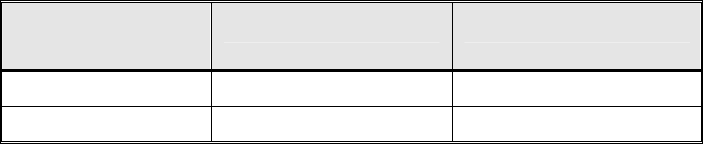
Table 2.1: EDACS D3100 RF Modem
EDACS D3100
MODEL FREQUENCY POWER LEVEL
TX 806-825 MHz 3 W
RX 851-870 MHz 3 W
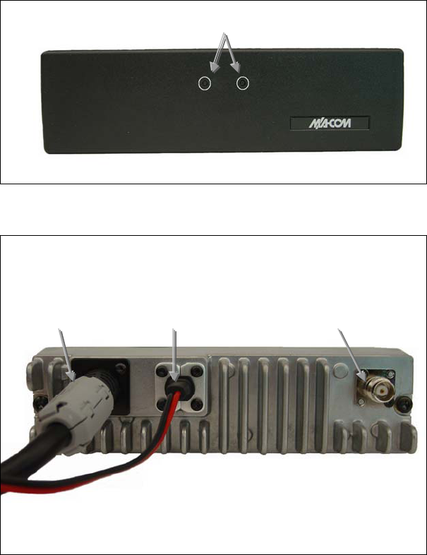
4. DESCRIPTION
D3100 comes ready to connect into a system with a personality containing
two systems. The power-on default system is an EDACS Data System named
“Site” containing an EDACS Control Channel (806.075 TX/851.075 RX) and
an EDACS Working Channel (820.975 TX/865.975 RX). The second system
is named “851” and is a conventional system for use in parametric testing and
calibration, should it be required.
LEDS
Figure 4-1: D3100 Front View
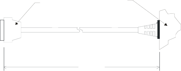
ANTENNA
CONNECTOR
POWER CABLE DATA CABLE
Figure 4-2: D3100 Rear View
10
4.1 DATA CONNECTOR FUNCTIONS
The data connector on the D3100, in shape and form, is similar to the “option
connector” of the E500M Mobile Radio made by M/A-COM. The following
pinouts and drawing define the cable and connections.
DATA CONNECTOR (J1) PIN ASSIGNMENTS (DB-25-Socket)
(Pin # - Pin Function)
1. NC
2. GND
3. IGN A+ (Not Used)
4. NC
5. RQST
6. Audio OUT
7. NC
8. RS485+
9. NC
10. NC
11. CTS
12. XDATAIN
13. EXT_MIC_L = GND
14. NC
15. NC
16. NC
17. NC
18. FPROG (Connect to A+ for
Programming Mode)
19. EXT_MIC_H
20. A+ (Connect to FPROG for
Programming MPode)
21. RS485-
22. GND
23. NC
24. RTS
25. XDATAOUT
NC = No Connection to
functional circuits in Modem
~ 350 mm
D3100 DATA CABLE
BACK OF D3100
DB-25 SOCKET
J1
W1
Figure 4-3: D3100 Data Cable
11

12
5. OPTIONS AND ACCESSORIES
Table 5-1: EDACS D3100 RF Modem Options and Accessories
DESCRIPTION PART NUMBER
D3100 Test Box TS103114V1
Roof Top Antenna AV102800V1
Yagi, 8dBd, Fixed-station Antenna AN103358V1
Control Unit, Orion, Scan, D2CP5L KRY 1011632/12
Data/Programming C-U Adapter Cable CA103067V1
Mounting Bracket Kit 19B802672P1
5.1 ADAPTER CABLE, CA103067V1
This accessory, part of the D3100 package, provides connection from the
D3100 Data Connector to a data connection, DB9-RS232 format, and to an
optional Orion Control Unit, should this be required. It also provides the
means of initiating “programming mode” and programming the D3100 from a
PC from its “COM” (serial) port. A drawing and wiring schematic of this
cable is shown in Figure 5-1.
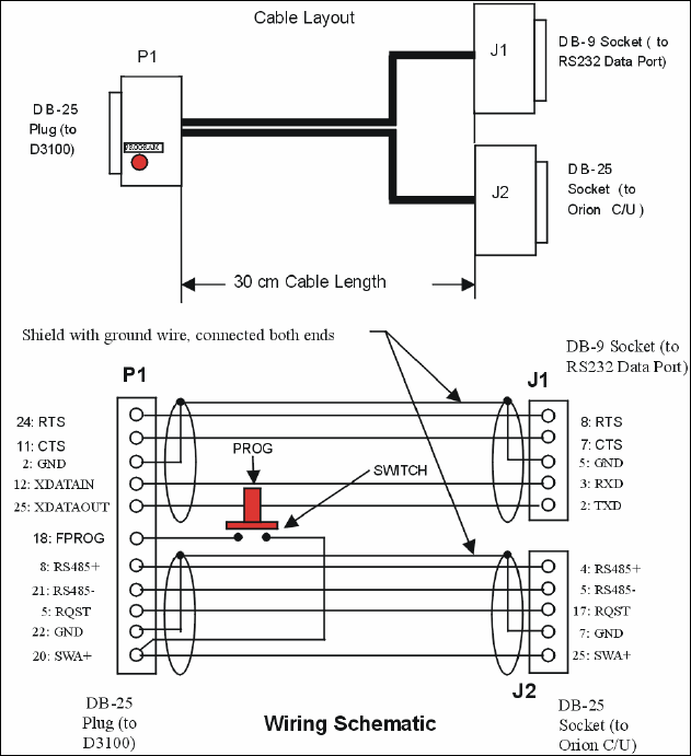
Figure 5-1: Adapter Cable CA103067V1
13
6. INSTALLATION
6.1 UNPACK AND CHECK THE EQUIPMENT
Before starting the installation, carefully unpack the equipment and inspect
the equipment for damage. If there is any damage, file a claim with the
carrier immediately.
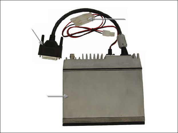
POWER
CABLE
DATA CABLE
D3100 UNIT
Figure 6-1: D3100 Unit
6.2 PLAN THE INSTALLATION
Before starting, plan the modem’s installation carefully so that it will be:
Functional •
•
•
•
Neat
Protected from water damage
Easy to service
The procedures in this section provide a guideline for installing the data
modem. In some applications it may be necessary to deviate slightly from the
recommended procedure and the order in which the equipment is installed.
14
15
To ensure the feasibility of the cable routes, it is suggested that the cables be
run prior to installation of the radio. Ensure slack is left in each cable so the
radio may be removed for servicing with all connections remaining intact.
D3100 is intended for installation within a weatherproof building, enclosure,
or vehicle. Typical installations are:
1. Elevated (usually beyond unassisted reach) in an outside enclosure with
co-located antenna,
2. Mounted inside a building and connected by RF cable to outside antenna
(usually above unassisted reach), or
3. Vehicle installation with vehicle rooftop antenna.
Install the D3100 so that the LED indicators on the front panel are visible
during operation.
If installation is within the United States, it is recommended the unit be
installed by one of the many M/A-COM Authorized Service Centers located
throughout the U.S. Personnel at these centers are experienced in installations
of this type and can provide a safe, neat, and functional installation.
6.3 INSTALL D3100 RF MODEM
Mount the antenna, following the included instructions, in a manner that
prohibits or precludes the presence of anyone within the prescribed MPE
Radius when the transmitter is on (see Table 1-1). Connect the antenna to the
D3100 antenna connector.
In order for the D3100 to communicate with the RS-232 device, the D3100
data cable must be connected to the RS-232 device using an appropriate data
cable or cable adapter. The accessory Data/Programming/C-U Adapter Cable
(CA103067V1) that comes with the D3100 provides this interconnect
function. When assembling hand-made adapters, make sure the corresponding
function is connected between the D3100 Data Cable and other devices.
Connection of non-corresponding (dissimilar) functions may cause damage to
the D3100 or connected equipment and/or failure of proper performance. (See
Section 4.1 for the data connector functions.)
Connect the polarized power plug of the D3100 power cable to a
corresponding polarized socket on a 13.6 +/-15% DC, regulated power
supply, the Red lead to positive (+) and Black lead to negative or ground (-).
When power is on, the Yellow LED is on.
If the correct personality has been entered, correct data connection, antenna
connection, and power connection are made, and power is on, then D3100 is
ready for data calls.
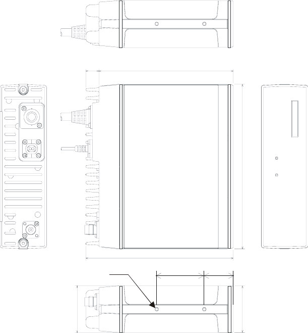
6.4 D3100 DIMENSIONS
14 144
176
158
50
51
D3100 MECHANICAL VIEWS
DIMENSIONS IN MILLIMETERS
31.5
M4, 4 Holes
16
17
7. WARRANTY
A. M/A-COM, Inc. (hereinafter "Seller") warrants to the original purchaser for use
(hereinafter "Buyer") that Equipment manufactured by or for the Seller shall be free from
defects in material and workmanship, and shall conform to its published specifications.
With respect to all non-M/A-COM Equipment, Seller gives no warranty, and only the
warranty, if any, given by the manufacturer shall apply. Rechargeable batteries are
excluded from this warranty but are warranted under a separate Rechargeable Battery
Warranty (ECR-7048).
B. Seller’s obligations set forth in Paragraph C below shall apply only to failures to meet the
above warranties occurring within the following periods of time from date of sale to the
Buyer and are conditioned on Buyer’s giving written notice to Seller within thirty (30)
days of such occurrence:
1. for fuses and non-rechargeable batteries, operable on arrival only.
2. for parts and accessories (except as noted in B.1) sold by Seller’s Service Parts
Operation, ninety (90) days.
3. for for all other equipment of Seller’s manufacture, one (1) year.
C. If any Equipment fails to meet the foregoing warranties, Seller shall correct the failure at
its option (i) by repairing any defective or damaged part or parts thereof, (ii) by making
available at Seller’s factory any necessary repaired or replacement parts, or (iii) by
replacing the failed Equipment with equivalent new or refurbished Equipment. Any
repaired or replacement part furnished hereunder shall be warranted for the remainder
of the warranty period of the Equipment in which it is installed. Where such failure cannot
be corrected by Seller’s reasonable efforts, the parties will negotiate an equitable
adjustment in price. Labor to perform warranty service will be provided at no charge
during the warranty period only for the Equipment covered under Paragraph B.3 and B.4.
To be eligible for no-charge labor, service must be performed at a M/A-COM factory, by
an Authorized Service Center (ASC) or other Servicer approved for these purposes
either at its place of business during normal business hours, for mobile or personal
equipment, or at the Buyer’s location, for fixed location equipment. Service on fixed
location equipment more than thirty (30) miles from the Service Center or other approved
Servicer’s place of business will include a charge for transportation.
D. Seller’s obligations under Paragraph C shall not apply to any Equipment, or part thereof,
which (i) has been modified or otherwise altered other than pursuant to Seller’s written
instructions or written approval or, (ii) is normally consumed in operation or, (iii) has a
normal life inherently shorter than the warranty periods specified in Paragraph B, or (iv)
is not properly stored, installed, used, maintained or repaired, or, (v) has been subjected
to any other kind of misuse or detrimental exposure, or has been involved in an accident.
E. The preceding paragraphs set forth the exclusive remedies for claims based upon
defects in or nonconformity of the Equipment, whether the claim is in contract, warranty,
tort (including negligence), strict liability or otherwise, and however instituted. Upon the
expiration of the warranty period, all such liability shall terminate. The foregoing
warranties are exclusive and in lieu of all other warranties, whether oral, written,
expressed, implied or statutory. NO IMPLIED OR STATUTORY WARRANTIES OF
MERCHANTABILITY OR FITNESS FOR PARTICULAR PURPOSE SHALL APPLY. IN
NO EVENT SHALL THE SELLER BE LIABLE FOR ANY INCIDENTAL,
CONSEQUENTIAL, SPECIAL, INDIRECT OR EXEMPLARY DAMAGES.
This warranty applies only within the United States.
M/A-COM, Inc. M/A-COM, Inc.
1011 Pawtucket Blvd. 221 Jefferson Ridge Parkway
Lowell, MA 01853 Lynchburg, VA 24501
1-877-OPENSKY 1-800-528-7711
ECR-7047C
NOTES
18
NOTES
19
NOTES
20
21