HARRIS TR-0039-E UHF MASTR-III Base Station User Manual MM102554V1RevB
HARRIS CORPORATION UHF MASTR-III Base Station MM102554V1RevB
UserManual.wiki
>
HARRIS
>
TR 0039 E User Manual
user manual
Navigation menu
Upload a User Manual
Namespaces
Wiki Guide
HTML
PDF
Info
Views
User Manual
Discussion / Help
Navigation

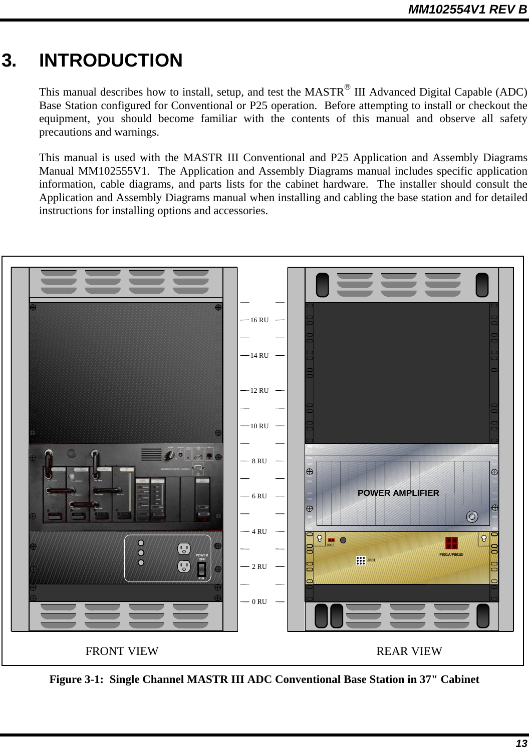

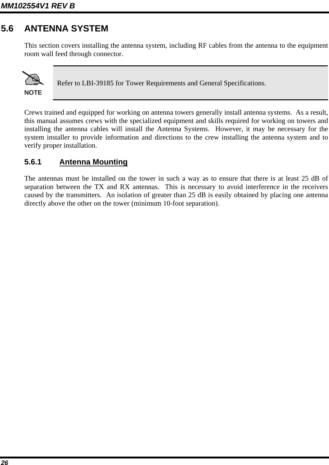
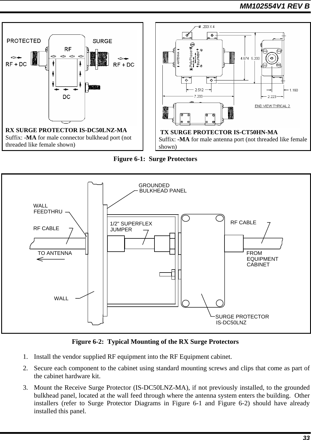
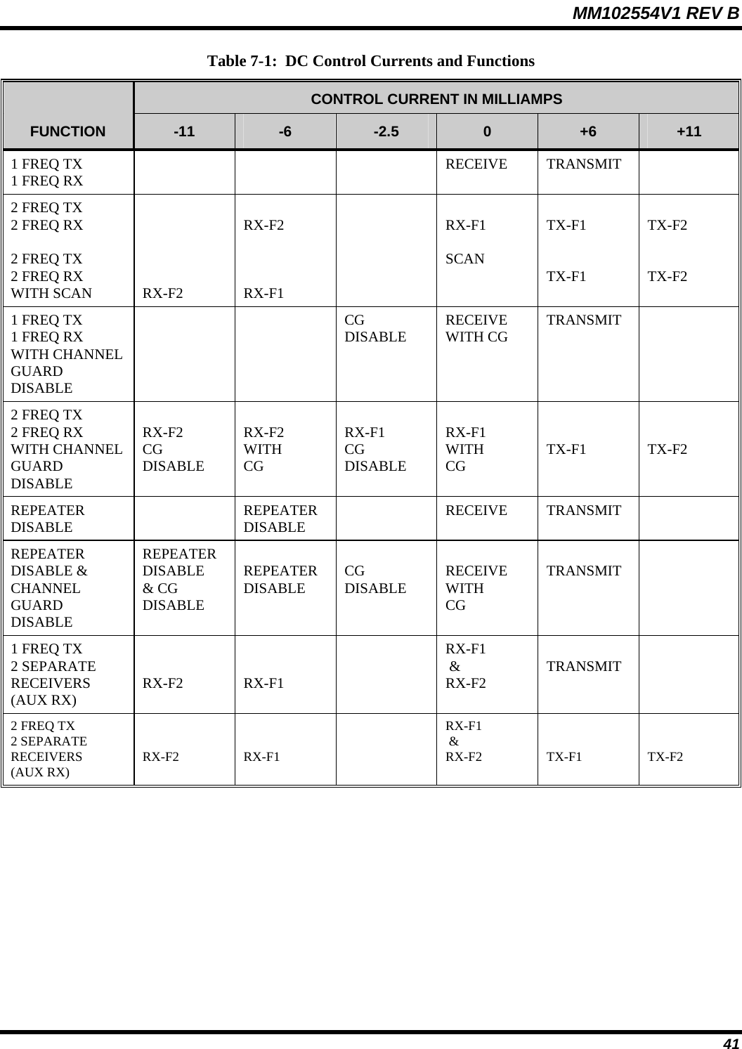
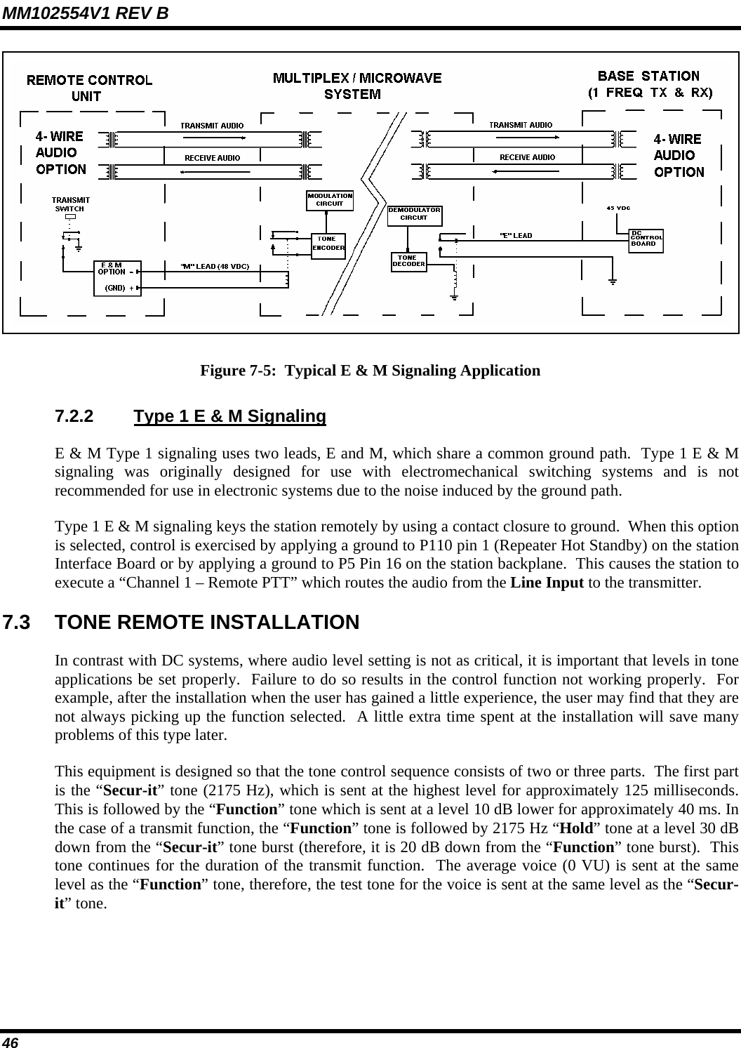
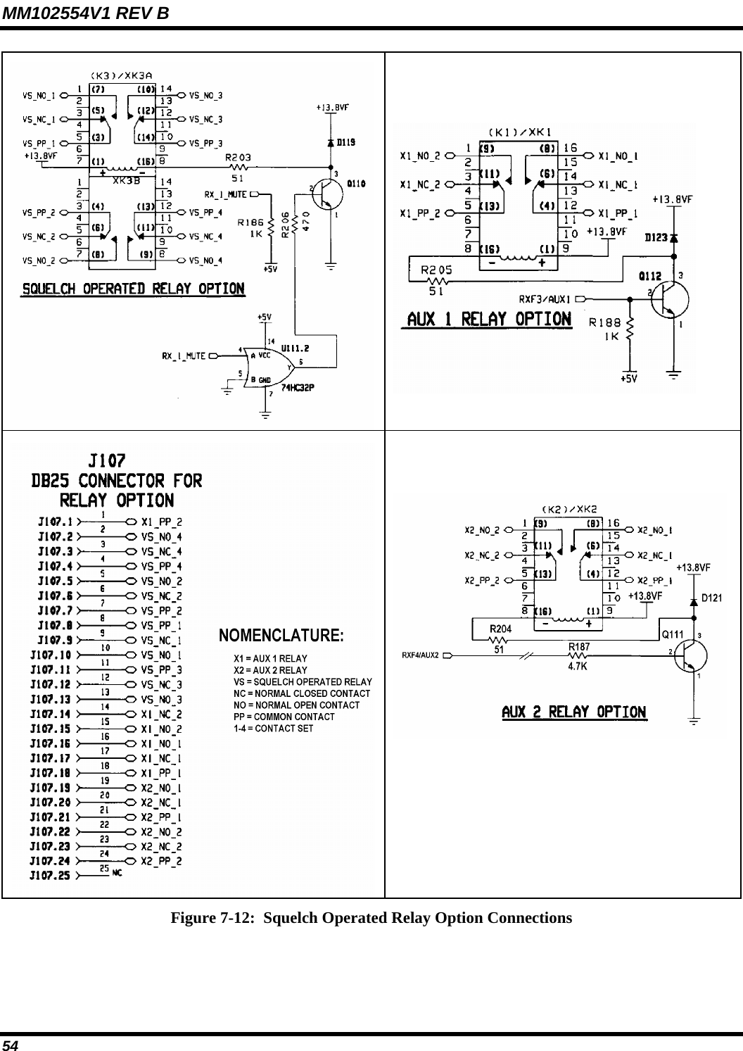
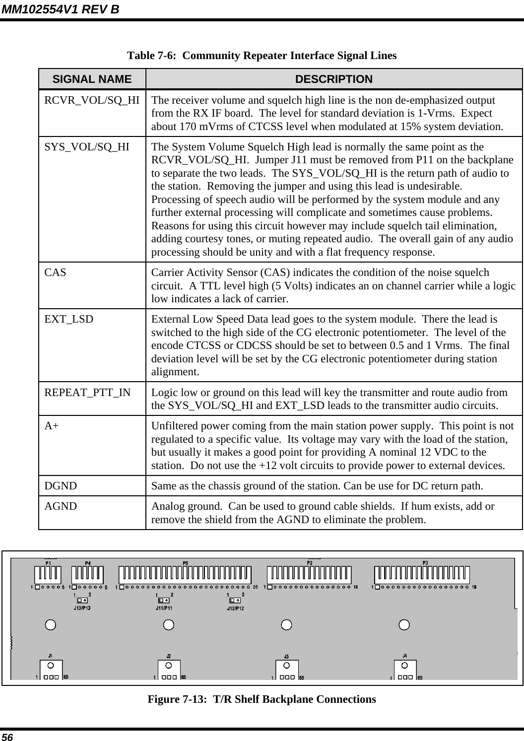
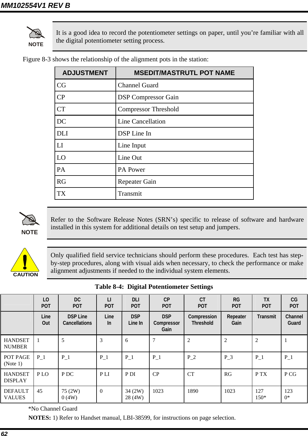
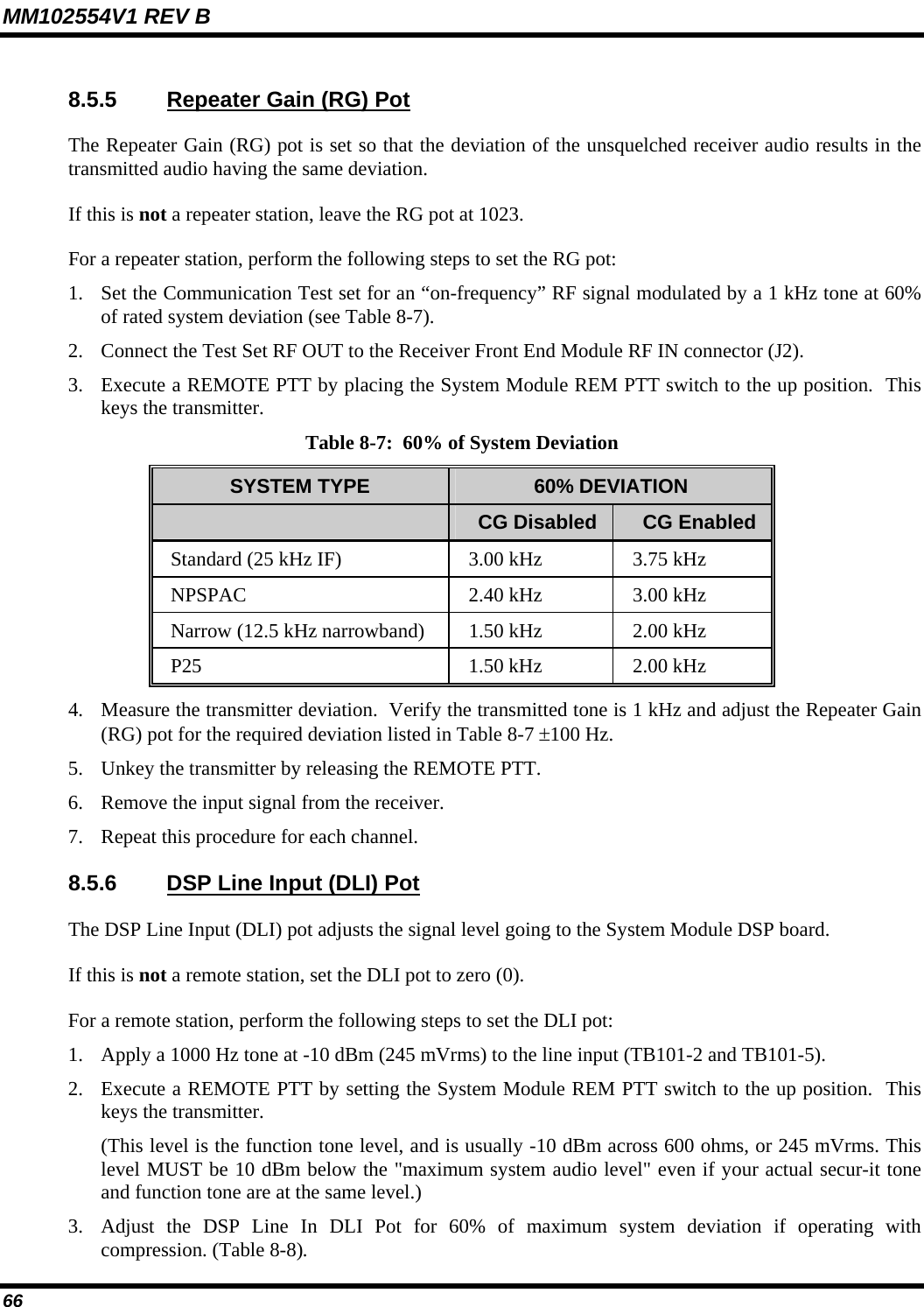
![MM102554V1 REV B 36 Table 6-1: RF Cables and Connectors Required CABLE REF. NUMBER CABLE DESCRIPTION CABLE TYPE CONNECTORS 1. RX RF coaxial cables. (Connects between the RX Multicoupler and Receiver RF inputs.) [V] 1/4-inch Superflex RF coaxial cable (FSJ1-50A). [U] Type BNC (M) - 41ASWB 1/4-inch Superflex connector. [W] Type N (M) - 41ASW 1/4-inch Superflex connector. 2. RX RF coaxial cable. (Connects between the RX Multicoupler and the Tower Top Amplifier Power Supply/RX Filter.) [M] 1/2-inch Superflex RF coaxial cable (FSJ4 -50B). [L] Type N (M) - 44ASW 1/2-inch Superflex connectors (qty. 2). 3. TX RF coaxial cables. (These cables connect between the transmitter outputs and the TX Combiner.) [M] 1/2-inch Superflex RF coaxial cable (FSJ4 -50B) [L] Type N (M) - 44ASW Superflex connector. [Y] Type N (M) - 49600-1, 1/2-inch Superflex right angle connector. 4. RX RF coaxial cables. (Connects between the RX Tower Top Amplifier Power Supply and the RX surge protector.) [M] 1/2-inch Superflex RF coaxial cable (FSJ4 -50B) [L] Type N (M) - 44ASW 1/2-inch Superflex connectors (qty. 2). 5. TX RF coaxial cables. (Connects between the Antenna Power Sensor and the TX surge protector.) [M] 1/2-inch Superflex RF coaxial cable (FSJ4 -50B) [L] Type N (M) - 44ASW 1/2-inch Superflex connectors (qty. 2). 6. TX RF coaxial cables. (Connects between the Surge Protector and the wall feedthrough connector.) [M] 1/2-inch Superflex RF coaxial cable (FSJ4 -50B) [L] Type N (M) - 44ASW 1/2-inch Superflex connectors. [N] Type N (F) - 44ASN 1/2-inch Superflex connectors. [ ] – References in brackets refer to material callouts in the Antenna Systems manual LBI-38983.](https://usermanual.wiki/HARRIS/TR-0039-E/User-Guide-500573-Page-36.png)