HARRIS TR-0041-E UHF MASTR-III Base Station - Paging User Manual MM102554V1RevB
HARRIS CORPORATION UHF MASTR-III Base Station - Paging MM102554V1RevB
HARRIS >
users manual

Installation Manual
MM102554V1
Rev. B, Dec- 04
MASTR® III
Conventional and P25
Base Stations
TABLE OF CONTENTS
Application and Assembly Diagrams........................MM102555V1
Antenna Systems.............................................................LBI-38983
Site Grounding and Lightning Protection ........AE/LZT 123 4618/1
Tower Requirements and Specifications......................... LBI-39185
Advanced Digital Capable

MM102554V1 REV B
2
MANUAL REVISION HISTORY
REV DATE REASON FOR CHANGE
R1A August 2003 Initial Release.
B December 2004 Modified Regulatory Section.
NOTICE!
This manual covers M/A-COM, Inc. products manufactured and sold by M/A-COM, Inc.
This device made under license under one or more of the following US patents: 4,590,473; 4,636,791; 5,148,482;
5,185,796; 5,271,017; 5,377,229.
The voice coding technology embodied in this product is protected by intellectual property rights including patent rights,
copyrights, and trade secrets of Digital Voice Systems, Inc. The user of this technology is explicitly prohibited from
attempting to decompile, reverse engineer, or disassemble the Object Code, or in any way convert the Object Code into
human-readable form.
MASTR and Voice Guard are registered trademarks and Aegis is a trademark of is a registered trademark of M/A-COM,
Inc.
Microsoft, Windows, and WindowsNT are registered trademarks of Microsoft Corporation
Pentium is a registered trademark of Intel Corporation.
All other brand and product names are registered trademarks, trademarks, or service marks of their respective holders.
NOTICE!
Repairs to this equipment should be made only by an authorized service technician or facility designated by the supplier.
Any repairs, alterations or substitutions of recommended parts made by the user to this equipment not approved by the
manufacturer could void the user's authority to operate the equipment in addition to the manufacturer's warranty.
This manual is published by M/A-COM, Inc. , without any warranty. Improvements and changes to this manual necessitated by typographical errors,
inaccuracies of current information, or improvements to programs and/or equipment, may be made by M/A-COM, Inc. , at any time and without notice.
Such changes will be incorporated into new editions of this manual. No part of this manual may be reproduced or transmitted in any form or by any means,
electronic or mechanical, including photocopying and recording, for any purpose, without the express written permission of M/A-COM, Inc.
Copyright© 2003 M/A-COM, Inc. All rights reserved.

MM102554V1 REV B
3
TABLE OF CONTENTS
Page
1. REGULATORY AND SAFETY INFORMATION............................................................................ 7
1.1 MAXIMUM PERMISSIBLE EXPOSURE LIMITS........................................................................ 7
1.2 DETERMINING MPE RADIUS......................................................................................................7
1.3 SAFETY TRAINING INFORMATION........................................................................................... 7
1.4 IMPORTANT SAFETY INFORMATION....................................................................................... 9
1.5 SAFETY SYMBOLS IN THIS DOCUMENT ............................................................................... 10
2. SPECIFICATIONS (GENERAL)...................................................................................................... 11
2.1 CABINET........................................................................................................................................ 11
2.2 STATION........................................................................................................................................ 11
2.3 INTERFACE................................................................................................................................... 12
3. INTRODUCTION ............................................................................................................................... 13
4. GENERAL INFORMATION............................................................................................................. 15
4.1 REFERENCE MANUALS ............................................................................................................. 15
4.2 OPTIONS........................................................................................................................................ 17
5. SITE PREPARATION........................................................................................................................ 19
5.1 INTRODUCTION........................................................................................................................... 19
5.2 FACILITY PREPARATION .......................................................................................................... 19
5.2.1 Floor Plan........................................................................................................................... 19
5.2.2 Equipment Cabinet Placement ........................................................................................... 19
5.2.3 Ceiling Requirements......................................................................................................... 20
5.2.4 Size and Weight Considerations ........................................................................................ 20
5.2.5 Operating Environment...................................................................................................... 20
5.3 POWER INSTALLATION............................................................................................................. 20
5.3.1 Existing Input Power.......................................................................................................... 20
5.3.2 AC Distribution.................................................................................................................. 21
5.3.3 Generator System............................................................................................................... 21
5.3.4 AC-DC Supply................................................................................................................... 21
5.3.5 Battery Backup................................................................................................................... 22
5.3.6 UPS System........................................................................................................................ 22
5.3.7 Electrical Power ................................................................................................................. 22
5.4 INTER-SITE COMMUNICATIONS ............................................................................................. 23
5.4.1 Hardwire Installation.......................................................................................................... 23
5.4.2 Leased Telephone Lines..................................................................................................... 24
5.4.3 T1 or E1 Links ................................................................................................................... 24
5.5 PROTECTIVE GROUNDING ....................................................................................................... 25
5.6 ANTENNA SYSTEM..................................................................................................................... 26
5.6.1 Antenna Mounting ............................................................................................................. 26
5.6.2 Transmission Lines ............................................................................................................ 27
5.7 QUALITY AUDIT.......................................................................................................................... 29
5.7.1 Antenna System ................................................................................................................. 29

MM102554V1 REV B
4
TABLE OF CONTENTS
Page
5.7.2 Electrical System................................................................................................................ 30
6. EQUIPMENT INSTALLATION ....................................................................................................... 31
6.1 INTRODUCTION........................................................................................................................... 31
6.2 UNPACKING EQUIPMENT ......................................................................................................... 31
6.3 EQUIPMENT INSTALLATION.................................................................................................... 32
6.3.1 Mounting Vendor Supplied RF Equipment ....................................................................... 32
6.3.2 Mounting Base Station Cabinet (Typical).......................................................................... 34
6.4 INTERIOR RF CABLING.............................................................................................................. 35
6.4.1 Cable Routing..................................................................................................................... 35
6.4.2 Install RF Cables................................................................................................................ 35
6.5 CONNECTING ELECTRICAL POWER....................................................................................... 37
6.5.1 AC Power Distribution....................................................................................................... 38
6.5.2 Generator Backup............................................................................................................... 38
6.5.3 AC-DC Supply................................................................................................................... 38
6.5.4 Battery Backup................................................................................................................... 38
6.5.5 UPS System........................................................................................................................ 39
6.6 POWER-UP SEQUENCE............................................................................................................... 39
7. DC AND TONE REMOTE CONTROL INSTALLATION ............................................................ 40
7.1 DC REMOTE INSTALLATION.................................................................................................... 40
7.1.1 Wiring Methods for DC Remote........................................................................................ 40
7.1.2 Installation Method 1 – Single Metallic Pair...................................................................... 43
7.1.3 Installation Method 2 – Single Metallic Pair with Earth Ground....................................... 43
7.1.4 Installation Method 3 - Metallic Control Pair, Audio Pair................................................. 43
7.1.5 Installation Method 4 - Full Duplex................................................................................... 45
7.2 E & M SIGNALING....................................................................................................................... 45
7.2.1 Standard (Type II) E & M Signaling.................................................................................. 45
7.2.2 Type 1 E & M Signaling .................................................................................................... 46
7.3 TONE REMOTE INSTALLATION............................................................................................... 46
7.3.1 Voting System Considerations........................................................................................... 48
7.3.2 Function Tones................................................................................................................... 48
7.3.3 Wiring Methods for Tone Remote ..................................................................................... 49
7.3.4 Installation Method 1 – Two Wire Tone Remote............................................................... 50
7.3.5 Installation Method 2 - Four Wire Tone Remote............................................................... 50
7.4 T/R SHELF REMOTE CONTROL CONNECTIONS ................................................................... 50
7.4.1 Interface Board Connections.............................................................................................. 50
7.5 SQUELCH OPERATED RELAY OPTION (SXSU3D)................................................................ 53
7.5.1 Installation.......................................................................................................................... 53
7.5.2 Operation............................................................................................................................ 53
7.6 SHARED REPEATER PANEL INSTALLATION........................................................................ 55
7.6.1 General ............................................................................................................................... 55
7.6.2 Repeater Panel Interface..................................................................................................... 55
8. STATION TEST AND ALIGNMENT PROCEDURES .................................................................. 58
8.1 INTRODUCTION........................................................................................................................... 58

MM102554V1 REV B
5
TABLE OF CONTENTS
Page
8.2 GENERAL ...................................................................................................................................... 58
8.3 SUPPORT EQUIPMENT REQUIRED .......................................................................................... 58
8.3.1 Hardware............................................................................................................................ 58
8.3.2 Software ............................................................................................................................. 59
8.4 STATION CONFIGURATION...................................................................................................... 60
8.5 STATION ALIGNMENT............................................................................................................... 61
8.5.1 Preparation ......................................................................................................................... 63
8.5.2 Station Pot Defaults............................................................................................................ 64
8.5.3 Channel Guard (CG) Pot.................................................................................................... 64
8.5.4 Transmit Limiter (TX) Pot................................................................................................. 65
8.5.5 Repeater Gain (RG) Pot ..................................................................................................... 66
8.5.6 DSP Line Input (DLI) Pot.................................................................................................. 66
8.5.7 Compressor Gain (CP) Pot................................................................................................. 67
8.5.8 Compressor Threshold (CT) Pot ........................................................................................ 68
8.5.9 DSP Line Cancellation (DC) Pot ....................................................................................... 68
8.5.10 Line Output (LO) Pot......................................................................................................... 69
8.5.11 P25 C4FM Deviation (DSP Module Adjustments)............................................................ 69
8.5.12 Enable the P25 Operation in the System Module............................................................... 69
8.5.13 Adjust P25 C4FM Deviation.............................................................................................. 70
8.5.14 SINAD Test........................................................................................................................ 71
8.5.15 Squelch Adjustment ........................................................................................................... 72
8.5.16 Transmitter Forward and Reverse Power........................................................................... 72
9. SYSTEM FUNCTIONAL TESTS...................................................................................................... 74
9.1 GENERAL ...................................................................................................................................... 74
9.2 SETUP............................................................................................................................................. 74
9.3 CONVENTIONAL RADIO TEST ................................................................................................. 74
9.4 P25 RADIO TEST .......................................................................................................................... 74
9.4.1 P25 Individual Calls........................................................................................................... 74
9.4.2 P25 Group Calls................................................................................................................. 74
9.5 REMOTE STATION OPERATION............................................................................................... 75
10. MODULE TESTING AND ALIGNMENT....................................................................................... 76
10.1 GENERAL ...................................................................................................................................... 76
10.2 BENCH TESTING.......................................................................................................................... 77
10.2.1 Procedure............................................................................................................................ 78
10.3 IN-STATION TESTING................................................................................................................. 79
10.3.1 Procedure............................................................................................................................ 79
10.4 CHANGING THE BASE STATION FREQUENCY..................................................................... 79
10.4.1 Vendor Equipment ............................................................................................................. 80
10.4.2 800 MHz Stations............................................................................................................... 80
10.4.3 UHF Stations...................................................................................................................... 81
10.4.4 VHF Stations...................................................................................................................... 81
10.5 STATION ADJUSTMENTS FOR REMOTE CONTROL OPERATION..................................... 82
10.5.1 Line Out Level Adjustment................................................................................................ 82
10.5.2 Line In Level Adjustment .................................................................................................. 83

MM102554V1 REV B
6
TABLE OF CONTENTS
Page
10.5.3 DSP Level Adjustments ..................................................................................................... 83
11. PREVENTATIVE MAINTENANCE ................................................................................................ 84
11.1 GENERAL ...................................................................................................................................... 84
11.2 BASE STATIONS .......................................................................................................................... 84
11.2.1 Test Equipment .................................................................................................................. 84
11.2.2 Tests ................................................................................................................................... 84
11.3 RF SYSTEM ................................................................................................................................... 85
11.3.1 Combiner............................................................................................................................ 85
11.3.2 Multicoupler....................................................................................................................... 85
11.3.3 Receive Filter ..................................................................................................................... 85
11.3.4 RF Cabling to Bulkhead..................................................................................................... 85
11.4 POWER SYSTEM.......................................................................................................................... 85
12. CHECKLISTS ..................................................................................................................................... 86
12.1 SITE DATA SHEET....................................................................................................................... 87
12.2 INSTALLER PROFILE DATA SHEET......................................................................................... 88
12.3 ANTENNA SYSTEM INSTALLATION CHECKLIST................................................................ 89
12.4 EQUIPMENT INSTALLATION CHECKLIST............................................................................. 90
12.5 POWER SYSTEM INSTALLATION CHECKLIST ..................................................................... 91
12.6 REPEATER TEST DATA .............................................................................................................. 92
12.7 PREVENTATIVE MAINTENANCE REPEATER TEST DATA................................................. 93
MM102554V1 REV B
7
1. REGULATORY AND SAFETY INFORMATION
1.1 MAXIMUM PERMISSIBLE EXPOSURE LIMITS
DO NOT TRANSMIT with this base station and antenna when persons are within the MAXIMUM
PERMISSIBLE EXPOSURE (MPE) Radius of the antenna. The MPE Radius is the minimum distance
from the antenna axis that ALL persons should maintain in order to avoid RF exposure higher than the
allowable MPE level set by the FCC.
WARNING
FAILURE TO OBSERVE THESE LIMITS MAY ALLOW ALL PERSONS WITHIN
THE MPE RADIUS TO EXPERIENCE RF RADIATION ABSORPTION, WHICH
EXCEEDS THE FCC MAXIMUM PERMISSIBLE EXPOSURE (MPE) LIMIT. IT IS
THE RESPONSIBILITY OF THE BASE STATION OPERATOR TO ENSURE THAT
THE MAXIMUM PERMISSIBLE EXPOSURE LIMITS ARE OBSERVED AT ALL
TIMES DURING BASE STATION TRANSMISSION. THE BASE STATION
OPERATOR IS TO ENSURE THAT NO BYSTANDERS ARE WITHIN THE RADIUS
LIMITS.
1.2 DETERMINING MPE RADIUS
THE MAXIMUM PERMISSIBLE EXPOSURE RADIUS is unique for each site and is determined at
during site licensing time based on the complete installation environment (i.e.. co-location, antenna type,
transmit power level, etc.). Determination of the MPE distance is the responsibility of the installation
licensee. Calculation of the MPE radius is required as part of the site licensing procedure with the FCC.
1.3 SAFETY TRAINING INFORMATION
WARNING
YOUR M/A-COM MASTR III BASE STATION GENERATES RF
ELECTROMAGNETIC ENERGY DURING TRANSMIT MODE. THIS BASE
STATION IS DESIGNED FOR AND CLASSIFIED AS “OCCUPATIONAL USE ONLY”
MEANING IT MUST BE USED ONLY IN THE COURSE OF EMPLOYMENT BY
INDIVIDUALS AWARE OF THE HAZARDS OF RF ENERGY AND THE WAYS TO
MINIMIZE EXPOSURE. THIS BASE STATION IS NOT INTENDED FOR USE BY
THE “GENERAL POPULATION” IN AN UNCONTROLLED ENVIRONMENT. IT IS
THE RESPONSIBILITY OF THE LISENSEE TO ENSURE THAT THE MAXIMUM
PERMISSIBLE EXPOSURE LIMITS ARE OBSERVED AT ALL TIMES DURING
TRANSMISSION. THE BASE STATION OPERATOR IS TO ENSURE THAT NO
BYSTANDERS COME WITHIN THE RADIUS OF THE LIMITS.
When licensed by the FCC, this base station complies with the FCC RF exposure limits when persons are
beyond the MPE radius of the antenna. In addition, your M/A-COM base station installation complies
with the following Standards and Guidelines with regard to RF energy and electromagnetic energy levels
and evaluation of such levels for exposure to humans:
MM102554V1 REV B
8
FCC OET Bulletin 65 Edition 97-01 Supplement C, Evaluating Compliance with FCC Guidelines
for Human Exposure to Radio Frequency Electromagnetic Fields.
American National Standards Institute (C95.1 – 1992), IEEE Standard for Safety Levels with
Respect to Human Exposure to Radio Frequency Electromagnetic Fields, 3 kHz to 300 GHz.
American National Standards Institute (C95.3 – 1992), IEEE Recommended Practice for the
Measurement of Potentially Hazardous Electromagnetic Fields – RF and Microwave.
CAUTION
TO ENSURE THAT YOUR EXPOSURE TO RF ELECTROMAGNETIC ENERGY IS
WITHIN THE FCC ALLOWABLE LIMITS FOR OCCUPATIONAL USE, DO NOT
OPERATE THE BASE STATION IN A MANNER THAT WOULD CREATE AN MPE
DISTANCE IN EXCESS OF THAT ALLOWABLE BY THE FCC.

MM102554V1 REV B
9
1.4 IMPORTANT SAFETY INFORMATION
The following general safety precautions must be observed during all phases of operation, service, and
repair of this product. Failure to comply with these precautions or with specific warnings elsewhere in
this manual violates safety standards of design, manufacture, and intended use of the product. M/A-COM
Inc. assumes no liability for the customer's failure to comply with these standards.
SAVE THIS MANUAL - It contains important safety and operating instructions.
1. Before using this equipment, please follow and adhere to all warnings, safety and operating
instructions located on the product and in the manual.
2. DO NOT expose equipment to rain, snow or other type of moisture.
3. Care should be taken so objects do not fall onto or liquids do not spill into the equipment.
4. DO NOT expose equipment to extreme temperatures.
5. DO NOT connect auxiliary equipment to the MASTR III System that is not recommended or sold by
M/A-COM. To do so may result in the risk of fire, electric shock or injury to persons.
6. GROUND THE EQUIPMENT - To minimize shock hazard, the station equipment cabinet must be
connected to an electrical ground.
If AC powered, the correct type of AC power cable and plug must be used. This cable and plug
assembly must conform to local standards and the installation of power cords must conform to local
standards and practices.
7. To reduce risk of damage to electrical cords, pull by plug rather than cord when disconnecting a unit.
8. Make sure all power cords are located so they will not be stepped on, tripped over, subjected to
damage or stress, or located such that they may be hazardous to health.
9. An extension cord should not be used unless absolutely necessary. Use of an improper extension
cord could result in a risk of fire or electric shock. If an extension cord must be used, ensure:
a) The extension conforms to local standards and practices,
b) The pins on the plug of the extension cord are the same number, size, and shape as those of the
plug on the power supply,
c) The extension cord is properly wired, in good condition, and
d) The wire size is capable of handling the AC ampere rating of unit/s being supplied.
10. DO NOT operate equipment with damaged power cords or plugs - replace them immediately.
11. DO NOT attempt to operate this product in an explosive atmosphere unless it has been specifically
certified for such operation.
12. To reduce risk of electric shock, isolate the unit and unplug from outlet before attempting any
maintenance or cleaning.
13. DO NOT attempt to operate this product with covers or panels removed. Refer all servicing to
qualified service personnel.
14. Use only fuses of the correct type, voltage rating and current rating as specified in the parts list.
Failure to do so can result in fire hazard.
15. GROUNDING AND AC POWER CORD CONNECTION - To reduce risk of electrical shock use
only a properly grounded outlet. The system components are equipped with electric cords having
MM102554V1 REV B
10
equipment grounding conductors and a grounding plug. Be sure all outlets are properly installed and
grounded in accordance with all local codes and ordinances.
16. DANGER - Never alter the AC cord or plug. Plug into an outlet properly wired by a qualified
electrician. Improper connection or loss of ground connection can result in risk of an electrical shock.
17. ELECTROSTATIC DISCHARGE SENSITIVE COMPONENTS - This station contains CMOS
and other circuit components that may be damaged by electrostatic discharge. Proper precaution must
be taken when handling circuit modules. As a minimum, grounded wrist straps should be used at all
times when handling circuit modules.
1.5 SAFETY SYMBOLS IN THIS DOCUMENT
The following conventions are used throughout this manual to alert the user to general safety precautions
that must be observed during all phases of operation, service, and repair of this product. Failure to comply
with these precautions or with specific warnings elsewhere in this manual violates safety standards of
design, manufacture, and intended use of the product. M/A-COM, Inc. assumes no liability for the
customer's failure to comply with these standards.
WARNING
The WARNING symbol calls attention to a procedure, practice, or the like, which, if not
correctly performed or adhered to, could result in personal injury. Do not proceed beyond a
WARNING symbol until the conditions identified are fully understood or met.
CAUTION
The CAUTION symbol calls attention to an operating procedure, practice, or the like,
which, if not performed correctly or adhered to, could result in damage to the equipment or
severely degrade the equipment performance.
NOTE
The NOTE symbol calls attention to supplemental information, which may improve system
performance or clarify a process or procedure.
The ESD symbol calls attention to procedures, practices, or the like, which could expose
equipment to the effects of Electro-Static Discharge. Proper precautions must be taken to
prevent ESD when handling circuit modules.

MM102554V1 REV B
11
2. SPECIFICATIONS (GENERAL)
2.1 CABINET
Cabinet Size (H x W x D): Total Rack Capacity
37-Inch Cabinet (37 x 21-1/2 x 18-1/4), (940 x 550 x 460 mm) 17
69-Inch Cabinet (69 x 23-3/16 x 21), (1750 x 590 x 533 mm) 33
83-Inch Cabinet (83 x 22-1/2 x 20-1/4), (2108 x 571 x 514 mm) 41
Weight (minimum) Continuous Duty Packed, Domestic Shipping
37-Inch Cabinet 150 lbs (68 kg) 165 lbs (75 kg)
69-Inch Cabinet (w/3 repeaters) 520 lbs (236 kg) 550 lbs (250 kg)
83-Inch Cabinet (w/3 repeaters) 550 lbs (250 kg) 580 lbs (263 kg)
Options Required Rack Units
MASTR III Base Station & Power Supply 8
Auxiliary receivers (1 or 2 receivers) 4
Battery Shelf and Batteries (CH1R) 6
Duplexers (factory installed) (DU1J, DU1K, DU1M) 3
Receiver Voting Selector 4
AegisTM/Voice Guard® Shelf (VG3E, VG3F) 1
Aegis Voice Guard Module and Shelf (VV1N, VW1J, VG3D, VV1S)
1 Rack Unit = 1.75-inches
2.2 STATION
Basic station occupies 8 RU
(includes T/R Shelf, PA, & Power. Supply)
Service Speaker: 1 watt at 8 ohms
Service Microphone: Transistorized Dynamic
Duty Cycle (EIA) Continuous: Transmit and Receive at 100%
Operating Temperature: -22° to +140°F (-30°C to +60°C)
Humidity (EIA): 90% at 122°F (50°C)
Input Power Source: 5 Amps at 120 VAC (±20%) 60 Hz or
3 Amps at 230 VAC (±15%) 50 Hz

MM102554V1 REV B
12
DC Input Power:
With 19D902797 Power Amplifier: 33 Amps at 13.8 VDC (transmit, full power)
25 Amps at 13.8 VDC (transmit, half power)
2.0 Amps at 13.8 VDC (receive only, standby)
With EA101292 Power Amplifier: 12 Amps at 26.4 VDC (transmit, full power)
8 Amps at 26.4VDC (transmit, half power)
0.5 Amps at 26.4 VDC (receive only, standby)
Antenna Connection: Type N
Altitude:
Operating: Up to 15,000 ft (4,570 m)
Shippable: Up to 50,000 ft (15,250 m)
2.3 INTERFACE
Line Interface
Line Interface 2-wire or 4-wire (programmable)
Line Cancellation (2-wire) 20 dB amplitude only (programmable)
Audio (line to transmitter)
Line Terminating Impedance 600 ohms (2-wire or 4-wire)
Line Input Level (adjustable) -20 dBm to +7 dBm
Frequency Response ±3 dB @ 300 to 3000 Hz
Remote Tone Control
Function Tones (Hz): 1050, 1150, 1250, 1350, 1450, 1550, 1650, 1750, 1850,
1950, & 2050
Secur-it Tone and Transmit Tone 2175 Hz
Permissible Control Line loss @ 2175 Hz: 30 dB
Audio (receiver to line)
Output Impedance to Line 600 ohms (2-wire or 4-wire)
Output Level to Line (adjustable): Zero to +7 dBm (Reference at 1 kHz)
Frequency Response +1 and –3 dB @ 300 to 3000 Hz
Hum and Noise, Noise Squelch: -55 dBm (Reference 7 dBm)
Tone Squelch: -30 dBm (Reference 7 dBm)
DC Remote Control Currents: -2.5 mA, ±6.0 mA, ±11.0 mA
Line Loop Resistance (maximum) 11K ohms (includes 3K ohm termination)
MM102554V1 REV B
13
3. INTRODUCTION
This manual describes how to install, setup, and test the MASTR® III Advanced Digital Capable (ADC)
Base Station configured for Conventional or P25 operation. Before attempting to install or checkout the
equipment, you should become familiar with the contents of this manual and observe all safety
precautions and warnings.
This manual is used with the MASTR III Conventional and P25 Application and Assembly Diagrams
Manual MM102555V1. The Application and Assembly Diagrams manual includes specific application
information, cable diagrams, and parts lists for the cabinet hardware. The installer should consult the
Application and Assembly Diagrams manual when installing and cabling the base station and for detailed
instructions for installing options and accessories.
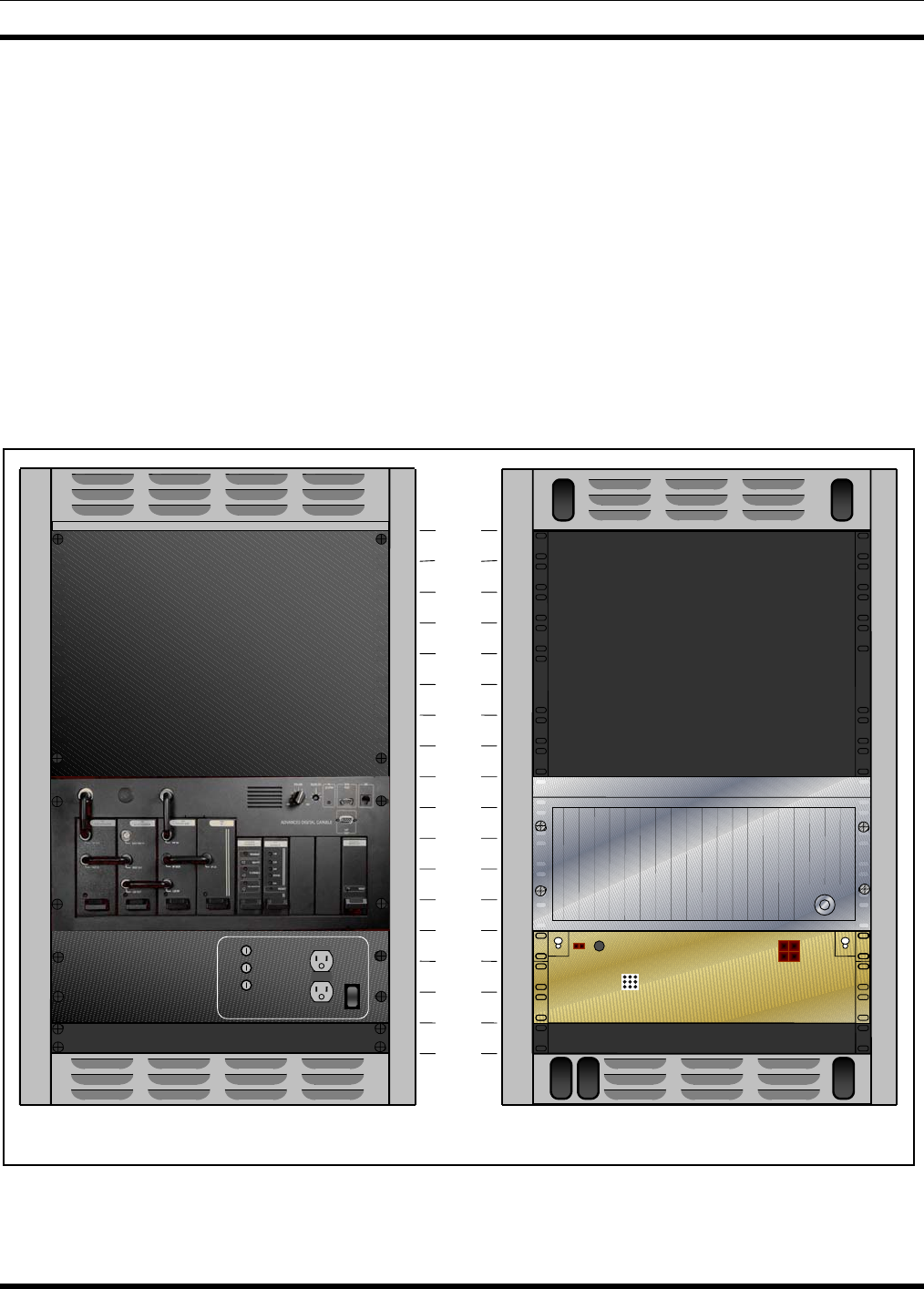
16 RU
14 RU
12 RU
10 RU
8 RU
6 RU
4 RU
2 RU
0 RU
J802
J801 F801A/F801B
POWER AMPLIFIER
FRONT VIEW REAR VIEW
POWER
OFF
ON
Figure 3-1: Single Channel MASTR III ADC Conventional Base Station in 37" Cabinet

MM102554V1 REV B
14
This manual is divided into the following chapters:
1. Regulatory and Safety Information – This chapter provides critical safety information governing
the installation and operation of the base station.
2. Specifications – This chapter provides the specifications for a typical conventional base station
installed in a 37" or 69" cabinet.
3. Introduction - This chapter provides a brief introduction on how this manual is structured.
4. General Information – This chapter lists many of the options and other technical manuals, which
may affect the installation of this base station.
5. Site Preparation - This chapter identifies site requirements and installation practices for the antenna
tower, transmission lines, and the equipment shelter.
6. Equipment Installation - This chapter provides instructions for unpacking and physically installing
the electronic equipment cabinets.
7. DC and Tone Remote Control Installation – This chapter provides information for configuring the
base station for operation with a DC or Tone Remote Control system.
8. Base Station Test and Alignment Procedures – This chapter provides detailed instructions for
testing and aligning each of the individual system components.
9. System Functional Tests - This chapter provides detailed instructions for verifying the overall
operation of the equipment as a system.
10. Module Testing and Alignment - This chapter provides details for bench testing or aligning
individual modules or testing and aligning the modules “in-station.” It also provides procedures for
changing the base station frequency.
11. Preventative Maintenance - This chapter defines those tests to be performed as part of Periodic
Preventative Maintenance.
12. Checklists – This chapter includes support features, such as Installation and Preventative
Maintenance Checklists.

MM102554V1 REV B
15
4. GENERAL INFORMATION
4.1 REFERENCE MANUALS
It may be necessary to consult one or more of the following manuals. These manuals will also provide
additional guidance if you encounter technical difficulties during the installation or testing process.
DESCRIPTION MANUAL NUMBER
OVERVIEW MANUALS
MASTR III Conventional ADC Base Station MM102558V1
MASTR III P25Conventional ADC Base Station MM102559V1
MASTR III CONVENTIONAL & P25 INSTALLATION MANUAL MM102554V1
MASTR III Conventional & P25 Application and Assembly Diagrams MM102555V1
MASTR III ADC T/R SHELF MM102244V1
System Module (19D902590G6) LBI-39176
Power Module (19D902589G2) LBI-38752
DSP MODULE (EA101800V1) MM101943V1
DATA MODULE (19D904558G1) LBI-38918
MASTR III RF PACKAGE: VHF (136 - 174 MHZ) MM102557V1
Transmit Synthesizer Module (19D902780G1) LBI-38640
Receive Synthesizer Module (19D902781G1) LBI-38641
Receiver Front End Module (19D902782G1) LBI-38642
Receiver IF Module (EA101401V1) MM101886V1
Power Amplifier (EA101292V10, V11, & V12) MM101383V2
MASTR III RF PACKAGE: UHF (380 - 512 MHZ) MM102557V2
Transmit Synthesizer Module (19D902780G3, G6-G10) LBI-38671
Receive Synthesizer Module (19D902781G3) LBI-38672
Receiver Front End Module (19D902782G11) LBI-39129
Receiver IF Module (19D902783G11) LBI-39123
Power Amplifier (19D902797G11) LBI-38674
MASTR III RF PACKAGE: 800 MHz LBI-39025
Transmit Synthesizer Module (19D902780G5) LBI-39026
Receive Synthesizer Module (19D902781G5) LBI-39027
Receiver Front End Module (19D902782G5) LBI-39028

MM102554V1 REV B
16
DESCRIPTION MANUAL NUMBER
Receiver IF Module (19D902783G5) LBI-39029
Power Amplifier, 110 Watt (EA101292V1) MM101383V1
OPTIONS AND ACCESSORIES
Electrostatic Discharge Protection LBI-38737
Antenna Systems Assembly Manual LBI-38983
Standard for Site Grounding and Protection LBI-39067
Duplexer Maintenance Manual LBI-38763
Base Station Power Supply Maintenance Manual (19D149978) LBI-38550
Base Station Power Supply Maintenance Manual (19D149979) LBI-38551
Emergency Power (Battery Charger) Maintenance Manual LBI-38625
AC Outlet Strip Maintenance Manual LBI-4841
Blower Kit Maintenance Manual LBI-4842
MASTR III Fuse Panel (12/24 Volt) Maintenance Manual LBI-30246
GETC Trunking Shelf Installation and Configuration Manual AE/LZB 119 2905/1
MASTR III Back-to-Back Repeater Configuration Manual LBI-39118
Conventional MASTR III Voice Guard Options Installation Manual AE/LZB 119 2905/2
Voice Guard System Manual LBI-31600
Voice Guard Interface Board Maintenance Manual LBI-38882
TEST AND DIAGNOSTICS
RF Module Test Fixture (TQ0650) - Model 344A4153P1
- Model TS101285V11 LBI 38805
MM101885V1
MASTR IIe Utility Handset Manual LBI-38599
MASTR III Programming Guide TQS3353 MM102518V1
MASTR III DSP Module Programming Guide TQS3413 MM102533V1

MM102554V1 REV B
17
4.2 OPTIONS
The MASTR III Conventional Base Station is available in the following frequencies and may be
combined with the options listed.
MODEL
NUMBER DESCRIPTION
SXGPNX 136-150.8 MHZ, CONVENTIONAL ADVANCED DIGITAL CAPABLE (ADC) P25,
110W
SXHPNX 150.8-174 MHZ, CONVENTIONAL ADVANCED DIGITAL CAPABLE (ADC) P25,
110W
SXGMCX 136-150.8 MHZ, CONVENTIONAL ADVANCED DIGITAL CAPABLE (ADC),
110W
SXHMCX 150.8-174 MHZ, CONVENTIONAL ADVANCED DIGITAL CAPABLE (ADC),
110W
SXRMCX 403-425 MHZ, CONVENTIONAL ADVANCED DIGITAL CAPABLE (ADC), 90W
SXPMCX 410-430 MHZ, CONVENTIONAL ADVANCED DIGITAL CAPABLE (ADC), 90W
SXTMCX 425-450 MHZ, CONVENTIONAL ADVANCED DIGITAL CAPABLE (ADC), 90W
SXUMCX 450-470 MHz, CONVENTIONAL ADVANCED DIGITAL CAPABLE (ADC), 100W
SXVMCX 470-494 MHz, CONVENTIONAL ADVANCED DIGITAL CAPABLE (ADC), 90W
SXWMCX 492-512 MHz, CONVENTIONAL ADVANCED DIGITAL CAPABLE (ADC), 90W
SX8MCX 800 MHZ, CONVENTIONAL ADVANCED DIGITAL CAPABLE (ADC), 100W
OTHER OPTIONS
CABINETS & FANS
SXCA1D 69" CABINET
SXCA1U 83" CABINET
SXCA1S 37" CABINET
SXMR1D 86" OPEN RACK
SXCA1X 45" OUTDOOR CABINET
SXFN1A 2-SPD FAN, 120 VAC. (Must be included when installing more than 1 repeater in a 69"
or 83" cabinet)
SXFA1L 2-SPD FAN, 230 VAC. (Must be included when installing more than 1 repeater in a 69"
or 83" cabinet)
SXFA1N 2-SPD FAN, 12 VDC. (Must be included when installing more than 1 repeater in a 69"
or 83" cabinet)
MM102554V1 REV B
18
MODEL
NUMBER DESCRIPTION
POWER SUPPLIES
SXPS5G POWER SUPPLY, 120 VAC, 60 HZ, 12 VDC, 33A. For UHF applications.
SXPS5H POWER SUPPLY, 230 VAC, 50 HZ, 12 VDC, 33A. For UHF applications.
SXPS5S POWER SUPPLY, 120 VAC, 60 HZ, 12/24 VDC, 33A. For 800 MHz and VHF
applications
SXPS5Y POWER SUPPLY, 230 VAC, 50 HZ, 12/24 VDC, 33A. For 800 MHz and VHF
applications
SXCN1Z OUTLET STRIP. 120 VAC
SXCN3H OUTLET STRIP, 230 VAC
PROGRAMMING
TQS3353 MASTR IIE/MIII PROGRAMMING SOFTWARE, Provides capability of changing
radio's functions and features. Includes TQ0619 Utility Programming Software.
TQ0653 MASTR IIE/MASTR III MSEDIT SOFTWARE
SPK9024 UTILITY HANDSET
TQS3413 DSP MODULE PROGRAMMING SOFTWARE
TQ3356 MASTR IIE/MIII PROGRAMMING CABLE

MM102554V1 REV B
19
5. SITE PREPARATION
5.1 INTRODUCTION
Before you install a MASTR III ADC Base Station, you need to prepare your site. Consider the
installation of the antenna system, space requirements, and weight. These issues are addressed in this
chapter.
This chapter is divided into the following sub-sections:
• Facility Preparation
• Power Installation
• Inter-Site Communication
• Protective Grounding
• Antenna System
• Power Up Sequence
5.2 FACILITY PREPARATION
This section provides information for preparing the facility prior to receiving or installing the MASTR III
ADC Base Station equipment.
5.2.1 Floor Plan
When creating the floor plan for cabinet placement, ensure consideration is given to safety, lighting, fire
suppression systems, access to other equipment and storage facilities in the room, etc.
5.2.2 Equipment Cabinet Placement
Direct access (for antenna cables and personnel) between the tower and the equipment room is necessary
for installation purposes).
The equipment cabinet you plan to install should be in an area that is:
• A dedicated equipment room or closet, wired in accordance with local electrical codes
• Large enough to allow easy access for service and maintenance
• Free of dust, smoke, and electrostatic discharge
• Properly ventilated
• Well lighted
NOTE
The recommended aisle spacing is 29.5 in. (750 mm).

MM102554V1 REV B
20
5.2.3 Ceiling Requirements
Consider the following ceiling requirements before you install the equipment cabinet:
• The ceiling should be clear of obstructions such as beams, heating and air conditioning ducts, water
pipes, and lights.
• The ceiling should not have sprinklers; however, appropriate fire protection devices should be
available.
5.2.4 Size and Weight Considerations
Before you install the equipment at your site, make sure that the equipment room can accommodate the
size and weight of the cabinet and the MASTR III ADC Base Station. To determine the total weight, add
the weight of the radio system (about 150 lbs, 68 kg for each radio system), and the weight of the rack.
Typical equipment size and weight is listed in the Specifications section. For the specific weight of
individual units or optional equipment, you should refer to the applicable maintenance manuals or product
Data Sheets.
5.2.5 Operating Environment
The equipment room or area where the MASTR III ADC Base Station is installed must meet the
environmental conditions listed in the Station Specifications section of this manual. In addition, the site
grounding must conform to the requirements of the Standards for Site Grounding and Protection manual
AE/LZT 123 4618/1.
Although the temperature requirements for individual components may be broader, when several units are
assembled together in a cabinet more heat is generated. Because of this condition, the ambient room
temperature outside the cabinet must be lowered to ensure the temperature inside the cabinet does not
exceed the limits for the equipment.
5.3 POWER INSTALLATION
In all cases where the customer provides a single AC supply input to a site, for AC or DC systems, the
input must be protected with a Joselyn AC protector, or equivalent. The AC Protector is installed after
the disconnect switch and must be connected to the external ground system.
If the AC supply is provided from wall outlets, the fuse panel breaker for the room must be sized for the
load of the proposed equipment that is to be installed in the site.
5.3.1 Existing Input Power
If the site already has an existing input power source, then the installers and a certified electrician should
ensure the power meets site requirements and is equipped with the necessary breakers to conform to both
design and local regulatory standards.
If the site input power source does not meet the site requirements or is not equipped with the necessary
breakers to conform to both design and local regulatory standards, refer the matter to the Site Manager.

MM102554V1 REV B
21
5.3.2 AC Distribution
If the site requires an AC distribution system to be installed, ensure it installed by qualified installers in
agreement with the customer. The Applications Engineer will provide the Site Manager with drawings
containing the installation requirements.
Ensure the input supply is isolated and power is not applied until the installation is complete.
5.3.3 Generator System
If the system already has a backup generator system providing backup supply to the site, inspect and test
the generator as defined in the equipment manuals.
Sites equipped with generator systems will use a manual or an automatic transfer switch system. Inspect
the customer system to ensure that it is fitted with the appropriate transfer switch system. This is to be
inspected and tested as defined in the equipment manuals.
If a new generator system is being installed, ensure it is installed by qualified generator installers in
agreement with the customer. When installing generator system remote controls, ensure that the installer
thoroughly understands the application and necessary generator connections. The Applications Engineer
will provide the Site Manager with drawings containing the installation requirements.
5.3.3.1 Manual Transfer Switch
If a Manual Transfer Switch is to be installed, the same team who installed the generator should install the
transfer switch. If this is an additional or new feature, the system is to be modified by qualified engineers
in agreement with the customer. The Applications Engineer will provide the Site Manager with drawings
containing the installation requirements.
5.3.3.2 Automatic Transfer Switch
If an Automatic Transfer Switch is to be installed, the same team who installed the generator should
install the transfer switch. If this is an additional or new feature, the system is to be modified by qualified
engineers in agreement with the customer. The Applications Engineer will provide the Site Manager with
drawings containing the installation requirements.
5.3.4 AC-DC Supply
If the system already has an AC-DC conversion system that meets the system requirements, then inspect
and test the system as defined in the equipment manuals.
If the site requires an AC-DC conversion system to be installed, this is to be performed by qualified
installers in agreement with the customer. The Applications Engineer will provide the Site Manager with
drawings containing the installation requirements.
The system will normally include input circuit breakers, a rectifier stage, converters and individual output
circuit breakers. These components will have their voltage and/or current specified on the site design
drawings. Ensure that input supply is isolated and not re-apply power until installation is complete.

MM102554V1 REV B
22
5.3.5 Battery Backup
A Battery backup system is normally installed to ensure smooth supply voltages during normal operation
or in the event of an input power failure.
If the site already has a battery backup system that meets the system’s requirements, then inspect and test
as defined in the equipment manuals.
The battery backup system will normally be a battery cell system. The backup battery system capacity
should be sufficient to provide the radio system with the desired voltage for a specified time. This should
also include power needed for the inverter equipment, input and output breakers, and either manual or
automatic switches to switch the system into circuit. The installation requirements will be in the site
design drawings agreed to by the customer and Application Engineer.
5.3.6 UPS
An Uninterruptible Power Supply (UPS) system may be an alternative to other backup supply options. It
may comprise some or all of the following components:
• Input supply and protection
• Various DC outputs (additional equipment that is required)
• Output protection
• Battery backup
• Bypass switch
• Automatic switch-over to generator
If the site already has an UPS system that meets the system requirements, then inspect and test the UPS as
defined in the equipment manuals.
If the site requires an UPS system to be installed, ensure the installation is made by a qualified installer in
agreement with the customer. The Applications Engineer will provide the Site Manager with drawings
containing the installation requirements.
5.3.7 Electrical Power
5.3.7.1 AC Power
Each MASTR III cabinet is equipped with its own AC power cord. Each of these power cords should be
connected to a separate circuit breaker. The following circuit breakers are recommended.
• 115 VAC (60 Hz) - a 20-amp circuit breaker for each power cord.
• 230 VAC (50 Hz) - a 15-amp circuit breaker for each power cord.
Receptacles must be installed within reach of the power cords and should be individually fused. They
may be installed on the wall behind the cabinets, in the floor under the cabinets, on the cable ladder above
the cabinets, or in the cabinet top cable ducts. The power cords must not be installed such that they cause
a hazard to persons in the site.
AC Power Installation must conform to local Installation Regulations.

MM102554V1 REV B
23
5.3.7.2 DC Power
When required, DC power options are available, but will be customized for the particular system. The
power supplies will be omitted from the cabinets and replaced by a fused DC panel. In this case, power
must be supplied to the repeaters from an external 13.8 or 24 VDC power source through a separate 30-
amp circuit breaker for each repeater.
The supply system will normally consist of an AC to DC converter, a Circuit Breaker Panel and various
DC-DC Converters sized for the equipment. DC feeds to the equipment that will be direct from the circuit
breaker panel.
5.3.7.3 Generators
Some systems, predominately remote sites, will require emergency generators with automatic switchover
systems. The generators must be connected to the external site grounding system and should be located
external to the equipment room.
Automatic switchover systems must be disabled during installation.
5.3.7.4 Battery Backup
Some systems will require a battery backup connected to the supply system in case of input power failure.
The battery bank should be located either separate from the equipment room or within the room but at a
point furthest from the entrance. It should have a separate fume extraction system or should be located
below the air extraction system for the site.
5.4 INTER-SITE COMMUNICATIONS
There are various types of Inter-Site Communication Systems, which require interfaces to be pre-installed
within the site. These interfaces will be the agreed demarcation points to which the Customer, Sub-
Contractor and system installer will make connections.
There are three types of inter-site connections:
• Hardwire Installation
¾ Direct Connection
• Leased Line
¾ Leased or Dedicated Telephone Line
• T1 or E1
¾ Leased T1 or E1
¾ Microwave
¾ Fiber Optic Cable
5.4.1 Hardwire Installation
When the media specified is to be Hardwire, that is point-to-point wiring on-site, the following
specifications apply:

MM102554V1 REV B
24
• Audio: 2-wire or 4-wire shielded cable; screen connected to site ground system and cable core is to be
solid in order that it may be punched-down.
• Data: Shielded twisted pair, shield connected to site ground system and cable core is to be solid in
order that it may be punched-down.
5.4.2 Leased Telephone Lines
When the media specified is to be Leased-Line via the local telephone company, request a 4-Wire 43202
Type 5 Data-Grade line from the local or regional telephone carrier. If using an equivalent line (old
specification is 3002 Data Grade), it must meet the following specifications:
• Frequency response:
1000 Hz Reference
500 - 2400 Hz -1 to +3 dB
300 - 2700 Hz -2 to +6 dB
• Max Frequency Error = ±5 Hz
• Max Net Loss = 16 dB
• Max Group Delay (800-2400Hz) = 2000µS
• Min S/N Ratio = 24 dB
The Telephone Company or customer will provide a point of interface for the telephone system within the
site known as the Demarcation Point. The installer will make necessary connections between the
Demarcation Point and the equipment
5.4.3 T1 or E1 Links
A T1 or E1 link may be leased from the Local or Regional Telephone Carrier. The physical link may be
via a Microwave System or via Fiber Optic cable. The Microwave or Fiber Optic system may also be
provided by the customer or sub-contracted from an alternate provider.
5.4.3.1 Leased T1/E1
If the link is Leased-Line T1 or E1, the carrier may provide the Multiplex (Mux) equipment and Channel
Service Unit (CSU). If so, they will connect to an agreed Demarcation Point (Punchblock) and collect the
data and modem audio as appropriate. If they do not provide the Mux or CSU, a Mux and CSU will be
provided and the demarcation point will be the appropriate T1/E1 interface on the Mux or CSU.
5.4.3.2 Microwave
The Microwave system may be provided by the Customer, M/A-COM, or a Sub-Contractor. Whichever
is the case, the Inter-Site Communications System should be in place prior to equipment installation and
the system provided will have a Demarcation Point to which the installer will connect the Inter-Site
Communications. This may be Punchblocks or the input connection to the multiplexer and the length of
the cross-connect cabling must be calculated to allow for the agreed location of the interface.
It is normal for the microwave radio to be close to its antenna and, in some installations, this may mean
some distance between radio and multiplexer. If the distance between radio and multiplex equipment is
excessive, consideration must be given to type of cable used for the connection, cable shield/ground,

MM102554V1 REV B
25
grounding through in-building cable routes, etc. This subject is to be discussed with microwave provider
and must conform to local installation regulations.
5.4.3.3 Fiber Optic
It is a requirement that the demarcation point for fiber optic cable is the fiber optic interface on the
multiplexer. If the multiplexer is not equipped with such an interface, a fiber optic line driver will be
provided and will be the point to which the cable is to be connected.
All other considerations are as for Microwave.
5.5 PROTECTIVE GROUNDING
For information on protective grounding outside the equipment room and general information for internal
grounding refer to the Site Grounding and Lightning Protection Standard manual AE/LZT123 4618/1.
However, a general rule for the external grounding system is that the resistance to ground should be five
(5) ohms or less, as measured with a Biddle DET2/2 Megger or equivalent, per IEEE STD 81-1983 or
local equivalent.
All equipment that is within the site must be connected to an internal halo ground of No. 2 AWG copper
wire six (6) inches below the ceiling. This interior halo ground must be connected to the external ground
system at each corner, using separate No. 2 AWG copper wires. The halo may be mounted on the cable
ladder, in the ducting or beneath the false floor.
All metal (electrically conductive) objects within the equipment room must be grounded. These objects
are divided into the following three (3) groups.
• Room Fixtures
• Power Supply
• RF equipment
All metallic fixtures and room parts, such as doorframes, sheet metal, ventilation louvers, air conditioning
units, light fixtures, etc., should be connected to the internal halo ground.
In addition to all other AC power protection, the AC power must be equipped with a Jocelyn AC
protector, or equivalent, placed immediately after the main disconnect switch. This protector must be
connected to the external ground system using a separate No. 2 AWG copper wire.
All equipment cabinets, cable trays, and protectors for cables connecting to this equipment must be
connected to a single grounding plate or bulkhead panel mounted on the wall where the antenna cables
enter the equipment room. This grounding plate must be connected to the external ground system using
two (2), two-inch wide copper strapping, or equivalent. A separate No. 6 AWG copper wire must be used
for each cabinet, each cable tray/ladder, and each group of cable protectors.
A few general rules of thumb are as follows:
• Make ground wires as short as possible and direct as possible - avoid bends if possible - absolutely no
bends with a radius of less than eight (8) inches.
• Surface area of ground wires is more important than cross sectional area.
• All connections must be clean, free of non-conductive coatings, and be coated with an anti-oxidant.

MM102554V1 REV B
26
5.6 ANTENNA SYSTEM
This section covers installing the antenna system, including RF cables from the antenna to the equipment
room wall feed through connector.
NOTE
Refer to LBI-39185 for Tower Requirements and General Specifications.
Crews trained and equipped for working on antenna towers generally install antenna systems. As a result,
this manual assumes crews with the specialized equipment and skills required for working on towers and
installing the antenna cables will install the Antenna Systems. However, it may be necessary for the
system installer to provide information and directions to the crew installing the antenna system and to
verify proper installation.
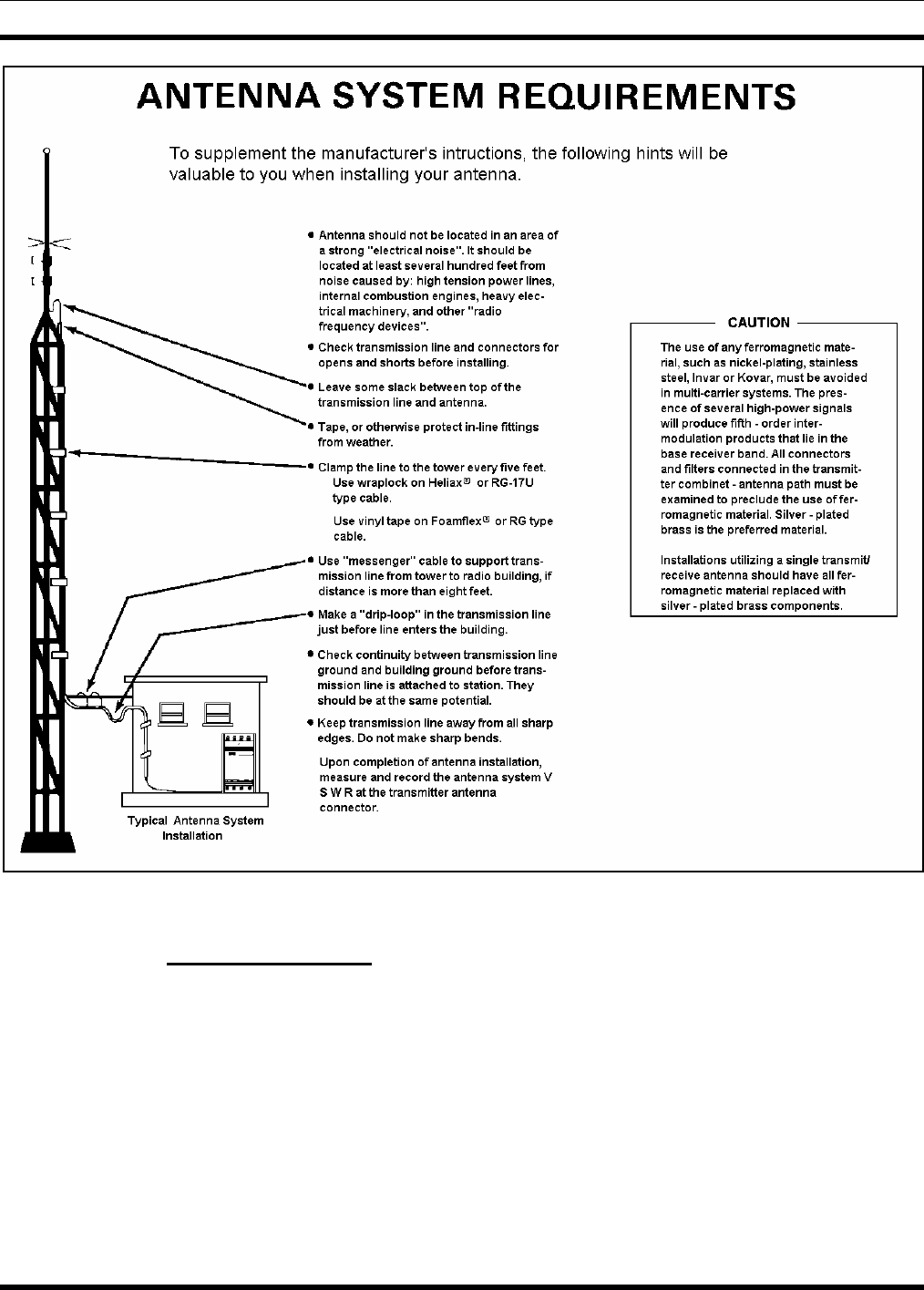
5.6.1 Antenna Mounting
The antennas must be installed on the tower in such a way as to ensure that there is at least 25 dB of
separation between the TX and RX antennas. This is necessary to avoid interference in the receivers
caused by the transmitters. An isolation of greater than 25 dB is easily obtained by placing one antenna
directly above the other on the tower (minimum 10-foot separation).
MM102554V1 REV B
27
Figure 5-1: Antenna System Requirements
5.6.2 Transmission Lines
When installing the transmissions lines, refer to the block diagram for UHF and 800 MHz Antenna
Systems contained in LBI- 38983.
5.6.2.1 Length
The length of the main coaxial cable for each antenna should be planned as a continuous run with no
connectors or splices between the antenna and the equipment room. Each cable includes a 50-foot
allowance for the distance from the bottom of the tower to the equipment room. Smaller diameter, more
flexible coaxial cables are used at both ends of the main coaxial cable to facilitate installation.

MM102554V1 REV B
28
5.6.2.2 Minimum Bending Radius
Always adhere to the minimum bending requirements provided by the manufacturer. For Andrew
Products, the values are:
CABLE SIZE BENDING RADIUS
1/4-inch 1-inch (25 mm)
1/2-inch 1.25-inch (32 mm)
7/8-inch 10-inches (250 mm)
1 5/8-inch 20-inches (510 mm)
5.6.2.3 Hoisting Grips
Hoisting grips provide the means to attach a lifting mechanism to the coaxial cable without damaging the
cable. Each hoisting grip is capable of safely lifting 200 feet of cable without causing damage.
Therefore, one hoisting grip is required for every 200-foot section of cable. The grips may be left
attached to the cable after the cable installation is completed.
Some situations may require more hoisting grips, such as:
• When installing cables on a tower mounted on top of another structure.
• When installing a cable whose length is greater than the height of the tower.
In these situations, additional hoisting grips should be ordered.
5.6.2.4 Hangers and Adapters
Coaxial cables on the tower should be secured at intervals of 3-5 feet (maximum).
Securing 7/8-inch and 1-5/8-inch diameter coaxial cables is accomplished by using either hangers or
hanger-adapter combinations. The hangers secure the cables to the tower structure by using prepunched
holes or attachment adapters.
• When the tower structure is prepunched with 3/4-inch holes, snap-in hangers are used (preferred
method).
• When the tower is prepunched with 3/8-inch holes, the hanger is secured by a 3/8-inch bolt.
For towers without prepunched holes, the hangers are attached with adapters. The type of adapter
depends on the type of tower structure. Adapters are available for either angle tower members or round
tower members.
Adapters for each antenna system are selected when ordering the system. If the coaxial cable must be
attached to a structure that is not compatible with any of the above hangers or adapters, then additional
materials or other special considerations may be required
To secure 1/4-inch or 1/2-inch vertical or horizontal coaxial cables of any size, use nylon cable ties.

MM102554V1 REV B
29
5.6.2.5 Weatherproofing
A kit of weatherproof tape is provided to protect coaxial connectors from the outside elements. One roll
of tape is sufficient to weatherproof four exposed outside connector joints.
5.7 QUALITY AUDIT
5.7.1 Antenna System
After the Antenna System is installed, it should be inspected before the installers leave. A checklist of
tasks performed on the antenna system is provided in section 12.3. Be sure to complete this visual
inspection before the installers leave, so any obvious errors can be corrected.
Using field glasses, if necessary, view the Antenna System from various positions on the ground. Using
copies of the Antenna System Installation Checklist 12.3, fill out a checklist for each antenna as you go
through the following inspection procedure. This will provide a record of the inspection, and of some
antenna information for future reference.
• Record the make of antenna.
• Record the type of antenna (omni or directional).
• Record the design gain of the antenna.
• If the antenna is directional, record the bearing of the main lobe. If it is omni, write "Omni" in the
data entry line.
• Record the height of the antenna above ground.
• Confirm that cable-hoisting grips were installed as required to prevent damage to the coaxial cable.
Hoisting grips should have been installed at the antenna end of the cable plus one for each 200 feet of
cable length.
• Confirm the cable is secured to the tower at intervals, which do not exceed 3 feet.
• Confirm the cable is grounded at the top of the tower.
• Confirm the cable is grounded at the point where it leaves the tower.
• Confirm the cable is grounded at the point where it enters the building.
• Confirm the coaxial cable run looks OK. The cable must be tight (nothing to flap in the breeze), have
no kinks, is one continuous run (no connectors or splices), and not exceed the minimum-bending
radius on any bend.
• Confirm the cable feed through is properly installed where the cable enters the building.
• Confirm the coaxial connectors have been properly weather sealed with tape.
• Confirm the cable entrance to the building has been properly weather sealed.

MM102554V1 REV B
30
5.7.2 Electrical System
If the electrical supply system has been installed by other than the company, it must be inspected to
ensure that it is safe and complies with both local regulations and the requirements of the site. Complete
the Power System Installation Checklist found in section 12.5, as required.
• Confirm that the supply system is rated to handle the full operating load of the equipment.
• Confirm that all outputs to which the site equipment will be connected have suitably rated breakers
installed.
• Confirm that electrical cabling to the equipment is correctly rated, installed and meets local
regulations.
• Confirm that the system is correctly grounded.
• Confirm that cables, bus bars and associated equipment are not a hazard to installers or maintenance
teams.
• Confirm that manuals for the supply system have been provided at the site.
MM102554V1 REV B
31
6. EQUIPMENT INSTALLATION
6.1 INTRODUCTION
NOTE
AC power adequate to meet system requirements, environmental control, civil works and
site preparation, and digital or voice grade phone lines must be available at the site prior
to installation.
WARNING
DO NOT apply power at this time!
During installation, all circuit breakers must be left in the OPEN position. Make sure all
equipment circuit breakers are in the OPEN position.
To prevent damage to equipment, ensure power is not accidentally applied at this time.
This chapter is divided into the following sub-sections:
• Unpacking the Equipment
• Equipment Installation
• Interior RF Cabling
• Connecting Electrical Power
• Quality Audit
6.2 UNPACKING EQUIPMENT
Station equipment is generally packed in one of the following ways:
• Bolted vertically to a mini pallet approximately 36” deep x 32” wide, with a corrugated cardboard
cover held down with two plastic straps. This technique is generally used for domestic shipments.
The mini pallet adds approximately three inches to the overall cabinet height. The weight varies
according to the content, but generally runs from 300 pounds to 600 pounds.
• Crated vertically or horizontally. This technique is generally used for open-racked equipment and
overseas shipments of 69-inch and 83-inch cabinets. Crates may contain one or several cabinets or
racks, and the dimensions and weight will vary accordingly. If size and weight limits are required,
contact the factory for special packing instructions.
Cabinets packed on mini pallets can be moved with a hand-truck, crates may need a forklift or pallet jack,
depending on the size. Wrenches will be needed to unbolt the cabinets from the mini pallets, and a
crowbar and hammer will be useful in opening the crates. Do not leave packed or unpacked equipment
exposed to the weather.
Upon receipt of the station equipment, carefully examine each carton. If any packaging damage is
detected, note the damage on the Bill of Lading.
MM102554V1 REV B
32
Move the cartons as close as possible to their mounting location.
Carefully unpack the equipment and examine each item. If there is any damage to the equipment, contact
the carrier immediately and have their representative verify the damage. If you fail to report the shipping
damage immediately, you may forfeit any claim against the carrier.
When unpacking the equipment, check the contents against the packing list. Contact your M/A-COM
representative and the carrier if any discrepancies are noted.
Carefully open each cabinet and inspect the contents to ensure that enclosed equipment has not been
damaged during delivery. If damage has occurred, note details of the damage and, if necessary, contact
the carrier immediately and have their representative verify the damage. Contact your M/A-COM
representative if the damage is such that installation cannot proceed.
6.3 EQUIPMENT INSTALLATION
NOTE
Refer to AE/LZT 123 4618/1 for Site Grounding and Protection Standards.
NOTE
These procedures are for M/A-COM standard installations. If the system is non-
standard, installation procedures may differ. In this event, installers should consult with
M/A-COM.
• This section provides instructions for installing the RF Equipment and for running the necessary RF
cables to the equipment room wall TX and RX feed through connectors.
6.3.1 Mounting Vendor Supplied RF Equipment
RF Equipment used for interfacing the Antenna System to the Repeaters may be pre-racked by M/A-
COM or dropped shipped from the individual vendors directly to the customer. If the RF equipment is
supplied directly from the vendor, it will be necessary to install the equipment into the RF Equipment
Cabinet.
NOTE
The system is designed to use either a Tower Top Amplifier or a Receiver Filter. When a
Tower Top Amplifier is used, the Receiver Filter is not required.
MM102554V1 REV B
33
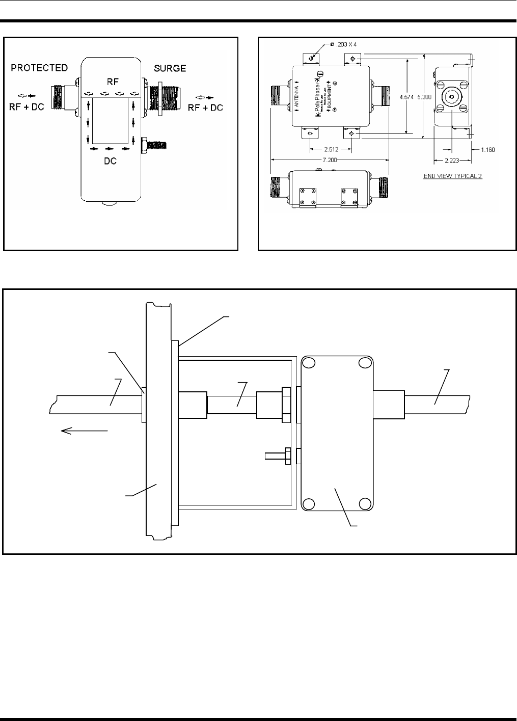
RX SURGE PROTECTOR IS-DC50LNZ-MA
Suffix: -MA for male connector bulkhead port (not
threaded like female shown)
TX SURGE PROTECTOR IS-CT50HN-MA
Suffix: -MA for male antenna port (not threaded like female
shown)
Figure 6-1: Surge Protectors
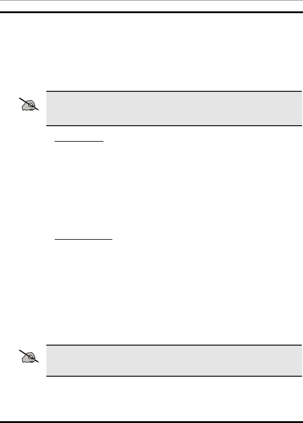
GROUNDED
BULKHEAD PANEL
IS-DC50LNZ
SURGE PROTECTOR
WALL
FEEDTHRU
RF CABLE 1/2" SUPERFLEX
JUMPER
WALL
TO ANTENNA
RF CABLE
FROM
EQUIPMENT
CABINET
Figure 6-2: Typical Mounting of the RX Surge Protectors
1. Install the vendor supplied RF equipment into the RF Equipment cabinet.
2. Secure each component to the cabinet using standard mounting screws and clips that come as part of
the cabinet hardware kit.
3. Mount the Receive Surge Protector (IS-DC50LNZ-MA), if not previously installed, to the grounded
bulkhead panel, located at the wall feed through where the antenna system enters the building. Other
installers (refer to Surge Protector Diagrams in Figure 6-1 and Figure 6-2) should have already
installed this panel.

MM102554V1 REV B
34
4. Mount the transmit surge protector (IS-CT50LNZ-MA) to the grounded bulkhead panel, located at
the wall feed through where the antenna system enters the building. Installers should have already
installed this panel. (Refer to Surge Protector Diagrams in Figure 6-1 and Figure 6-2)
5. Install Top Cover (if cabinet).
6.3.2 Mounting Base Station Cabinet (Typical)
The following tools and materials are typically needed to fasten the cabinets to concrete floor (if installing
on wood flooring - do not use lead anchors):
• ½" x 2" Lag screws (4 per rack)
• 1/2" Flat washers (4 per cabinet/rack)
• Lead anchor for 1/2" lag screws (4 per rack)
• Measuring tape
• Heavy-duty marker (suitable for marking coarse concrete)
• Eye protection
• Ear protection
• Drill with masonry bit (see size marked on anchor)
• 1/4" x 24" Flexible plastic tubing (blow debris out of hole)
• Hammer (seat anchor in hole)
• Wrench (screw lag screw into anchor)
The following additional hardware is supplied with each optional open-rack. The hardware enables the
installer to fasten adjacent side rails together at the top and bottom:
• 3/8" x 1 1/2" Hex machine screws (2 per open-rack)
• 3/8" Hex nut (2 per open-rack)
• 3/8" Flat washers (4 per open-rack)
• 3/8" Lock washer (2 per open-rack)
The RF Equipment cabinet(s) should be located at a point nearest the RF Bulkhead, where the antenna
cables enter the building. This allows the antenna cable lengths to be minimized.
Position the cabinet(s) on the floor exactly where they are to be mounted. Allow one (1) meter (3 feet) of
free space in front of and behind each cabinet, to allow the cabinet doors to swing completely open. Also
allow one (1) meter (3 feet) of free space around at least one end of each row of cabinets, to get to the
back of the cabinets.
Mark the position of the mounting bolt holes on the floor using the four holes in the bottom of each
cabinet as a template. Move the cabinets, drill the holes in the floor for the screw anchors, seat the
anchors in the holes, reposition the cabinets, and fasten the cabinets down with lag screws (use a flat
washer under each lag screw head, to prevent damage to the cabinet).
MM102554V1 REV B
35
6.4 INTERIOR RF CABLING
Some RF coaxial cables may be pre-made and included with the system. However, most cables must be
custom made, on site, to the required length. Table 6-1 lists the cables and associated connectors, which
are typically fabricated at the site.
The coaxial cable and connectors are supplied in bulk. To cut the cable properly for easy connector
attachment, use an Andrew's "EASIAX" coaxial cable cutting tool (or equivalent).
NOTE
When installing the RF or power cables, refer to the Antenna System Block Diagrams in LBI-
38983 and the Application Assembly Diagrams in technical manual MM102556V1 for in
installation instructions.
6.4.1 Cable Routing
If cabinet-top cable ducts are supplied, install per LBI-38875 using the hardware provided. However,
leave the duct covers off until the site wiring is complete. These cable ducts are not available for open-
type equipment racks.
Larger systems should make use of cable ladders for ease of installation and maintenance. It is preferable
that dual ladders be used for large systems such that audio and data may occupy one level of the ladder
and RF and power occupy the other. If dual systems are not available, ensure maximum separation
between Audio/Data runs and RF/Power runs.
Install as shown on the site plans and install all grounding leads across ladder section connections.
6.4.2 Install RF Cables
Assemble and install the RF coaxial cables. Be careful not to exceed minimum bend radius (refer to Site
Preparation - Antenna System for specifications).
Refer to the Antenna Systems Assembly Manual LBI-38983 and applicable vendor manuals for TX and
RX connection points. (For specially engineered systems, refer to the Site Antenna System drawings for
the site.)
Use cable ties to secure the coaxial cables to the back rails of the cabinets. Ensure cables do not impede
access to the internal equipment and the installation appears neat and orderly. Exercise caution and
ensure cables are routed away from the sharp ends of mounting screws (on the backside of the equipment
rails). Allow room for equipment mounting screws to be removed and re-installed without damaging the
cables.
NOTE
If overhead cable ladders are used, ensure the RF cable are of sufficient length to run from
point A to point B via the cable ladder. Do not loosely ‘drape’ cables on the top of cable
ladders or racks.
Begin the cable installation by installing receiver cables first. Then complete the installation by installing
the transmitter cables.

MM102554V1 REV B
36
Table 6-1: RF Cables and Connectors Required
CABLE
REF.
NUMBER CABLE DESCRIPTION CABLE TYPE CONNECTORS
1. RX RF coaxial cables.
(Connects between the RX
Multicoupler and Receiver RF
inputs.)
[V] 1/4-inch Superflex RF
coaxial cable (FSJ1-50A). [U] Type BNC (M) - 41ASWB 1/4-inch
Superflex connector.
[W] Type N (M) - 41ASW 1/4-inch
Superflex connector.
2. RX RF coaxial cable.
(Connects between the RX
Multicoupler and the Tower
Top Amplifier Power
Supply/RX Filter.)
[M] 1/2-inch Superflex RF
coaxial cable (FSJ4 -50B). [L] Type N (M) - 44ASW 1/2-inch
Superflex connectors (qty. 2).
3. TX RF coaxial cables. (These
cables connect between the
transmitter outputs and the TX
Combiner.)
[M] 1/2-inch Superflex RF
coaxial cable (FSJ4 -50B) [L] Type N (M) - 44ASW Superflex
connector.
[Y] Type N (M) - 49600-1, 1/2-inch
Superflex right angle connector.
4. RX RF coaxial cables.
(Connects between the RX
Tower Top Amplifier Power
Supply and the RX surge
protector.)
[M] 1/2-inch Superflex RF
coaxial cable (FSJ4 -50B) [L] Type N (M) - 44ASW 1/2-inch
Superflex connectors (qty. 2).
5. TX RF coaxial cables.
(Connects between the
Antenna Power Sensor and
the TX surge protector.)
[M] 1/2-inch Superflex RF
coaxial cable (FSJ4 -50B) [L] Type N (M) - 44ASW 1/2-inch
Superflex connectors (qty. 2).
6. TX RF coaxial cables.
(Connects between the Surge
Protector and the wall
feedthrough connector.)
[M] 1/2-inch Superflex RF
coaxial cable (FSJ4 -50B) [L] Type N (M) - 44ASW 1/2-inch
Superflex connectors.
[N] Type N (F) - 44ASN 1/2-inch
Superflex connectors.
[ ] – References in brackets refer to material callouts in the Antenna Systems manual LBI-38983.

MM102554V1 REV B
37
6.4.2.1 Receive Section
Use the following procedures to install the RF cables for the receive section of the system. Refer to LBI-
38983 and Table 6-1 for cable references.
1. Route receiver RF cables (item 1) from the RX Multicoupler to the receiver RF input connectors.
One cable is required for each receive channel as labeled (RX CH 1, RX CH 2, RX CH 3, etc.).
NOTE
These cables may be connected inside the repeater cabinets at the factory. If they are
already connected to the repeaters, they only need to be routed to the RX Multicoupler.
Pay close attention to cable labeling and connect to the correct port on the Multicoupler.
2. Make sure any unused ports on the RX Multicoupler are terminated with 50-ohm loads (refer to the
vendor Maintenance Manual).
3. Connect a 1/2-inch Superflex RF cable (item 2) from the input of the RX Multicoupler to the output
of the Tower Top Amplifier Power Supply (or RX Filter, if installed).
4. Connect a 1/2-inch Superflex RF jumper from the surge protector to a wall feedthrough.
5. Connect a 1/2-inch Superflex RF cable (item 4) from the output of the Tower Top Amplifier Power
Supply (or RX Filter) to the receive surge protector.
6. Connect the Tower Top Amplifier Power Supply and the RX Multicoupler to the appropriate supply
source or power strip. (Ensure the circuit breaker is OFF prior to plugging cord into power source.)
6.4.2.2 Transmit Section
Use the following procedures to install the RF cables for the transmit section of the system. Refer to LBI-
38983 and Table 6-1 for cable references.
1. Route the TX RF (1/2-inch Superflex) cables (item 3) from the power output connector of each
transmitter to the RF Equipment Cabinet/rack.
2. Connect each TX RF (item 3) cable to the TX Combiner input corresponding to the channel number
as labeled (TX CH1, TX CH2, TX CH3, etc.).
3. To make any other required connections to the TX Combiner, refer to Installation & Operation
Manual supplied by vendor.
4. Connect the TX Combiner channels as instructed in the vendor manual.
5. Connect a 1/2-inch Superflex RF jumper (item 6) from the surge protector to the Bulkhead Panel.
6. Connect a 1/2-inch Superflex RF cable (item 5) from the TX Combiner - RF Power Sensor (if
supplied) output to the TX surge protector.
6.5 CONNECTING ELECTRICAL POWER
The site, regardless of complexity of equipment, is to be powered-up in a controlled fashion. This is to
ensure that, should a power problem occur, possible damage can be limited and the problem can be
quickly located and resolved. In general, a site is to be powered-up with all breakers open and site
equipment that is isolated. Breakers will be closed in a logical progression through the power system
until it can be applied direct to the site equipment. Annotate findings on the Electrical Power Checklist.

MM102554V1 REV B
38
6.5.1 AC Power Distribution
Before connecting power to the base station equipment, perform the following tests to ensure correct
voltage levels and breaker operation.
1. Visually inspect the power distribution panel and note any discrepancies.
2. Test the input supply and confirm that the input supply can provide the correct voltage and current.
3. Visually inspect the breakers on the input to the site. Confirm that they are rated as required for the
site loading. The requirement is stated in the site survey requirements document.
4. Confirm that the power cabling is sufficient for the expected load.
5. Confirm operation of input AC protection breaker.
6. Close each breaker in turn to provide AC power to individual equipment.
7. If the breakers are fitted with an over voltage test facility, perform the test once an equipment has
been powered up.
8. Confirm that each station or cabinet supply is operating correctly and that output voltages are as
required.
6.5.2 Generator Backup
If the generator system has remote control or alarms to be connected to the site equipment, ensure these
are connected prior to test. Also ensure that the fuel system is ready for operation and that the system is
correctly grounded.
1. Switch the generator on.
2. Confirm output supply is as specified in the drawings.
3. If remote control option is installed, remotely control the operation of the generator.
4. If alarms are configured, toggle the alarm conditions and confirm that the alarm system correctly
reports the conditions.
6.5.3 AC-DC Supply
Ensure that each converter output breaker to the equipment is open.
1. Confirm operation of input AC protection breaker.
2. Confirm that the rectifier output is at the desired voltage.
3. Confirm that the rectifier output breaker operates.
4. With converter output breakers open, confirm each converter output is as rated.
5. Close each breaker in turn to provide DC power to individual equipment.
6. Confirm that each station or cabinet supply is operating correctly and that output voltages are as
required.
6.5.4 Battery Backup
Prior to powering on the site, it is essential to inspect the battery system and confirm that the installation
is safe, that the connectivity is correct, that the cells are serviceable and that the installation conforms to
regulatory and site requirements.

MM102554V1 REV B
39
1. Confirm that the battery system connectivity is correct as detailed in the Site Drawings.
2. Confirm the battery system is electrically safe.
3. Confirm that “wet” cells have been prepared and have adequate fume extraction capability provided.
4. Confirm that all cabling is safely installed such that it is not a hazard.
5. Confirm that output voltage is as specified across all the cells.
6. With site equipment breakers disconnected, connect the battery system to the site power system.
7. Confirm that the battery system is in Charge mode.
8. Confirm that the power system is providing power to the open site equipment breakers by checking
voltage across breakers.
9. Close the Repeater Cabinet #1 equipment breakers to connect power to that cabinet only. Confirm
that equipment powers up correctly and that there are no abnormal indications.
10. Confirm that battery power has been applied to site equipment power distribution equipment.
11. Confirm that the battery supply applied on site equipment is as specified.
12. When the battery cell system has fully charged, disconnect the AC input to the site by opening the
site supply protection breaker.
13. Confirm that the battery supply can provide power to the site equipment as required.
6.5.5 UPS
Follow the instructions in the UPS installation manual and test the operation of the UPS. Ensure the UPS
can provide power to the site equipment as required.
6.6 POWER-UP SEQUENCE
Open all site equipment power distribution breakers or power down station or cabinet power supplies.
1. Close customer power breaker to apply power into site power system. Confirm that input power is at
rated voltage and that there are no abnormal indications.
2. If the system is fitted with auxiliary or backup power systems, connect these to the power system.
Check backup power is at the rated voltage, is correctly applied to the main power source equipment
that is either in normal or emergency modes and that there are no abnormal indications.
3. If the system provides DC to the site, connect the power source to the converters. Check the outputs
of each converter and confirm that the output is as designed and rated for the equipment.
4. Apply power to each repeater, or to the repeater cabinet, if power is not provided individually to each
station. Switch the repeaters on, one-by-one. Confirm that there are no abnormal indications.
5. Apply power to the any ancillary cabinets on site and confirm that there are no abnormal indications.

MM102554V1 REV B
40
7. DC AND TONE REMOTE CONTROL INSTALLATION
This chapter provides information for connecting a DC or Tone Remote Control system to the base
station.
The DC Current or Tone Signaling Remote controllers available from M/A-COM are full-function
controllers used to operate the base station from a remote location. The DC Current Remote Controller
can control and display up to four channels, and the Tone Remote Controller can control and display up
to eight channels. Parallel controllers can receive indications of transmit and remote selections. In
addition, 10 or more dispatch points (remote controllers) can operate a single base station.
Wiring between a remote controller and the base station is usually made using direct wire lines or leased
telephone lines. This wiring may also be used in conjunction with a Multiplex or Microwave system.
7.1 DC REMOTE INSTALLATION
The MASTR III Conventional ADC Base Station can be remotely controlled by DC control currents. A
DC remote control unit can initiate a transmission, listen to received audio, and select or deselect certain
base station functions. Control current signaling from a DC remote control unit consists of applying
different current levels on a wire pair having DC continuity. The six control current levels used for
controlling the base station are:
• -11 milliamperes • 0 milliamperes
• -6 milliamperes • +6 milliamperes
• -2.5 milliamperes • +11 milliamperes
The following station functions can be controlled by using control currents:
• Repeater Disable
• Channel Guard Monitor
• Transmit Frequency Selection
• Receive Frequency Selection
• Scan
• Receiver Selection (Auxiliary Receiver selection)
Table 7-1 is a list of DC Control Currents and their corresponding functions.
7.1.1 Wiring Methods for DC Remote
DC Remote Control units can be connected to the base station in one of four connection schemes. The
choice of which installation method should be used is based on the cost, availability, and performance as
compared to controller’s operating environment.
Table 7-2 provides a description of the four methods and gives some of the advantages and disadvantages
of each method. After the table, installation procedures are available for each method. The procedures
contain detailed wiring instructions. These instructions assume a M/A-COM DC Remote Control unit is
being connected to the base station.

MM102554V1 REV B
41
Table 7-1: DC Control Currents and Functions
CONTROL CURRENT IN MILLIAMPS
FUNCTION -11 -6 -2.5 0 +6 +11
1 FREQ TX
1 FREQ RX RECEIVE TRANSMIT
2 FREQ TX
2 FREQ RX
2 FREQ TX
2 FREQ RX
WITH SCAN
RX-F2
RX-F2
RX-F1
RX-F1
SCAN
TX-F1
TX-F1
TX-F2
TX-F2
1 FREQ TX
1 FREQ RX
WITH CHANNEL
GUARD
DISABLE
CG
DISABLE RECEIVE
WITH CG TRANSMIT
2 FREQ TX
2 FREQ RX
WITH CHANNEL
GUARD
DISABLE
RX-F2
CG
DISABLE
RX-F2
WITH
CG
RX-F1
CG
DISABLE
RX-F1
WITH
CG
TX-F1
TX-F2
REPEATER
DISABLE REPEATER
DISABLE RECEIVE TRANSMIT
REPEATER
DISABLE &
CHANNEL
GUARD
DISABLE
REPEATER
DISABLE
& CG
DISABLE
REPEATER
DISABLE
CG
DISABLE
RECEIVE
WITH
CG
TRANSMIT
1 FREQ TX
2 SEPARATE
RECEIVERS
(AUX RX)
RX-F2
RX-F1
RX-F1
&
RX-F2
TRANSMIT
2 FREQ TX
2 SEPARATE
RECEIVERS
(AUX RX)
RX-F2
RX-F1
RX-F1
&
RX-F2
TX-F1
TX-F2
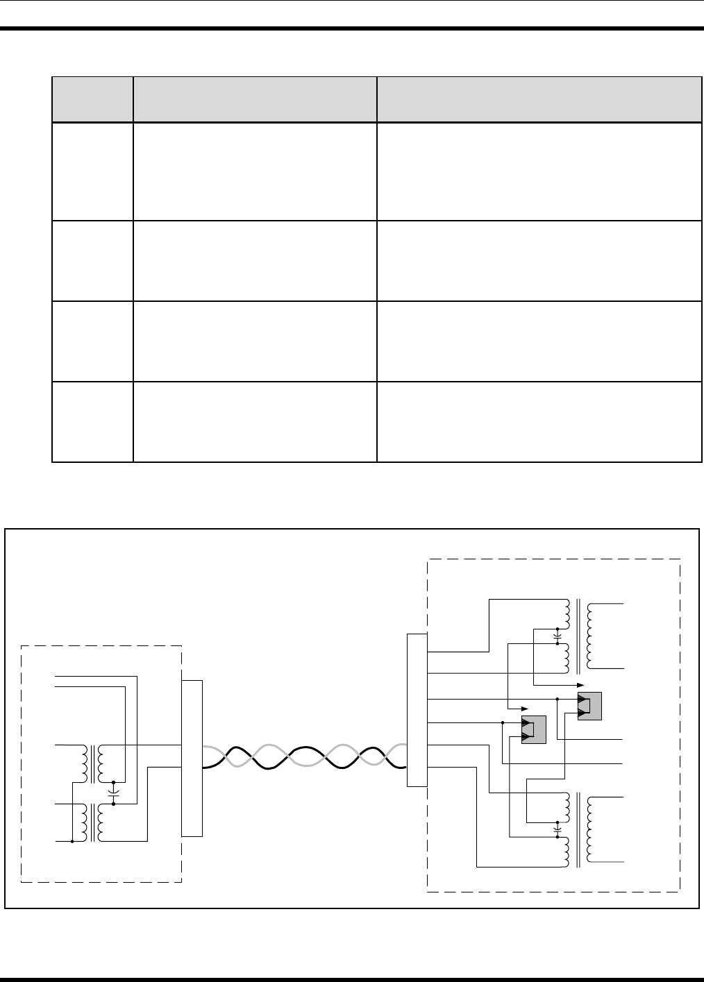
MM102554V1 REV B
42
Table 7-2: DC Remote Wire Line Installation Methods
METHOD DESCRIPTION ADVANTAGES OR
DISADVANTAGES
1 Single metallic pair (the control
currents are simplexed to line, a two
wire cable is required).
This is the most economical method. It is
dependable where earth ground currents may be
large or good earth grounds cannot be obtained.
The keying clicks will be heard on paralleled
remotes.
2 Single metallic pair (the control
currents are simplexed line to earth
ground, a two wire cable is
required).
This method is also economical. It minimizes
keying clicks in paralleled remotes. Large ground
currents may result in interference with control
functions if remotes are located near sub-stations.
3 Two wire pairs needed. One is a
voice grade pair for bidirectional
audio and the other is a metallic pair
used for control current.
Provides excellent performance by eliminating
keying clicks and providing no path for ground
loop current. However, it does require two wire
pairs.
4 Two wire pairs needed. One is a
voice grade pair for receive audio.
The second is a metallic pair for
transmit audio and control Currents.
Provides full duplex operation in which the
remote can receive and transmit at the same time.
However, it does require two wire pairs.
J101,
J109,
TB101
2
5
3
4
1
6
T101
LINE_A
LINE_B
DC_CNTLR
DC_CNTLR
Telephone Line +
Telephone Line -
VDC
RX
TX
_
+
DC Remote Controller
MASTR III ADC T/R SHELF
Interface Board
DC Control +
DC Control -
J104
1
2
3
J105
1
2
3
T102
DPLX_LINE_A
DPLX_LINE_B
Duplex Audio +
Duplex Audio -
+
_
2
5
1
6
3
4
Figure 7-1: Method 1 – Single Metallic Pair
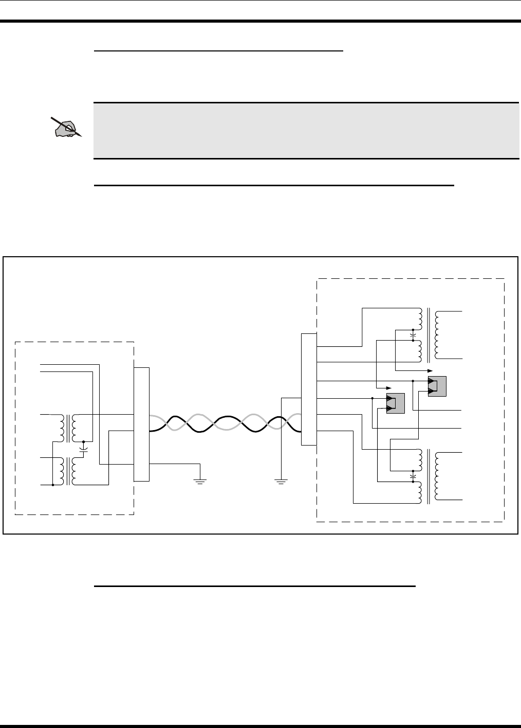
MM102554V1 REV B
43
7.1.2 Installation Method 1 – Single Metallic Pair
1. Connect the metallic pair to TB101-3 (red) and TB101-4 (green). Refer to Figure 7-1.
2. On the Interface Board, place a jumper on J104, pins 1 & 2 and on J105, pins 1 & 2.
NOTE
Polarity must be maintained, if the metallic control pair is being used for DC control.
7.1.3 Installation Method 2 – Single Metallic Pair with Earth Ground
1. Connect the metallic pair to TB101-3 (red) and TB101-4 (green). Refer to Figure 7-2.
2. On the Interface Board, place a jumper on J104, pins 1 & 2 and on J105, pins 1 & 2.
3. Connect a wire between TB101-6 and earth ground.
J101,
J109,
TB101
T101
LINE_A
LINE_B
DC_CNTLR
DC_CNTLR
Telephone Line +
Telephone Line -
VDC
RX
TX
_
+
DC Remote Controller
MASTR III ADC T/R SHELF
Interface Board
DC Control +
DC Control -
J104
1
2
3
J105
1
2
3
T102
DPLX_LINE_A
DPLX_LINE_B
Duplex Audio +
Duplex Audio -
+
_
2
5
1
6
3
4
2
5
3
4
1
6
Figure 7-2: Single Metallic Pair with Earth Ground
7.1.4 Installation Method 3 - Metallic Control Pair, Audio Pair
1. Connect the audio pair to TB101-3 (red) and TB101-4 (green). Refer to Figure 7-3.
2. On the Interface Board, remove jumpers from J104 and J105.
3. Connect the control metallic pair to TB101-1 (white) and TB101-6 (blue).
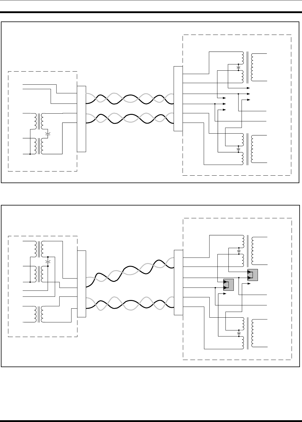
MM102554V1 REV B
44
J101,
J109,
TB101
T101
LINE_A
LINE_B
DC_CNTLR
DC_CNTLR
Telephone Line +
Telephone Line -
VDC
RX
TX
+
-
DC Remote Controller
MASTR III ADC T/R SHELF
Interface Board
DC Control +
DC Control -
J104
1
2
3
J105
1
2
3
T102
DPLX_LINE_A
DPLX_LINE_B
Duplex Audio +
Duplex Audio -
-
+1
6
3
4
2
5
2
5
1
6
3
4
AUDIO
Figure 7-3: Metallic Control Pair, Audio Pair
J101,
J109,
TB101
T101
LINE_A
LINE_B
DC_CNTLR
DC_CNTLR
Telephone Line +
Telephone Line -
VDC
RX
TX
_
+
DC Remote Controller
MASTR III ADC T/R SHELF
Interface Board
DC Control +
DC Control -
J104
1
2
3
J105
1
2
3
T102
DPLX_LINE_A
DPLX_LINE_B
Duplex Audio +
Duplex Audio -
+
_
2
5
1
6
3
4
TX AUDIO
1
6
3
4
2
5
RX AUDIO
VDC
Figure 7-4: Method 4 – Full Duplex

MM102554V1 REV B
45
7.1.5 Installation Method 4 - Full Duplex
1. On the Interface Board, place a jumper on J104, pins 3 & 4 and on J105, pins 3 & 4.
2. Connect the transmit metallic pair to TB101-2 (black) and TB101-5 (yellow). Refer to Figure 7-4.
3. Connect the remote receive pair to TB101-3 (red) and TB101-4 (green).
7.2 E & M SIGNALING
E & M lead signaling systems derive their name from certain historical designations of the signaling leads
on circuit drawings. An “M” lead is associated with the transMit function or Mouth, while the “E” lead
is associated with the recEive function or Ear. In some two-way radio systems with remote control, E &
M Signaling may be the only type of control offered by the available carrier circuits.
Generally, both 4-Wire Audio and E & M Signaling options are used to interface between the radio and
carrier systems. However, 2-Wire Audio can be used in the two-way radio portion of the control system
if hybrids are installed to provide transition between the 2-Wire and 4-Wire connections. Usually the E &
M Signaling is separated from the audio (separate line) in both 2-Wire and 4-Wire installations.
7.2.1 Standard (Type II) E & M Signaling
The Standard or Type II E & M (+48 V) signaling method uses four wires for signaling, the “E” pair at
the Remote Control Console and the “M” pair at the base station. This configuration uses four wires for
audio. One voice grade pair is used for TX audio and the other pair is used for RX audio. This is
illustrated in Figure 7-5, which also shows the interface between a two-way radio system and a
multiplex/microwave system.
At the console a regulated -48 VDC output (or -24 VDC with minor modifications) is applied to the "M"
lead when the TRANSMIT switch is pressed. This -48 VDC activates a tone encoder (usually 3825 Hz)
in the multiplex rack. The tone encoder modulates the carrier frequency, which is transmitted over the
microwave link.
At the station end of the microwave link, the signal is demodulated and the 3825 Hz tone operates a tone
decoder in the multiplex rack. The output of the decoder results in a contact closure, which applies +48
VDC (or +24 VDC) to the DC control lines on T/R Shelf. The DC Current Detection Circuit detects the
presence of the +48 V signaling as a +11mA current. The station then executes a “Channel 1 – Remote
PTT” which then keys the transmitter and routes the audio from the Line Input to the transmitter.
7.2.1.1 Installation
1. Connect the E & M control lines to TB101 pins 1 and 6.
2. Connect the remote control transmit pair (which modulates the transmitter) to TB101-2 and -5.
3. Connect the remote control receive pair (which listens to the receiver) to TB101-3 and TB101-4.
4. Remove jumpers from J104 and J105 on the Interface Board
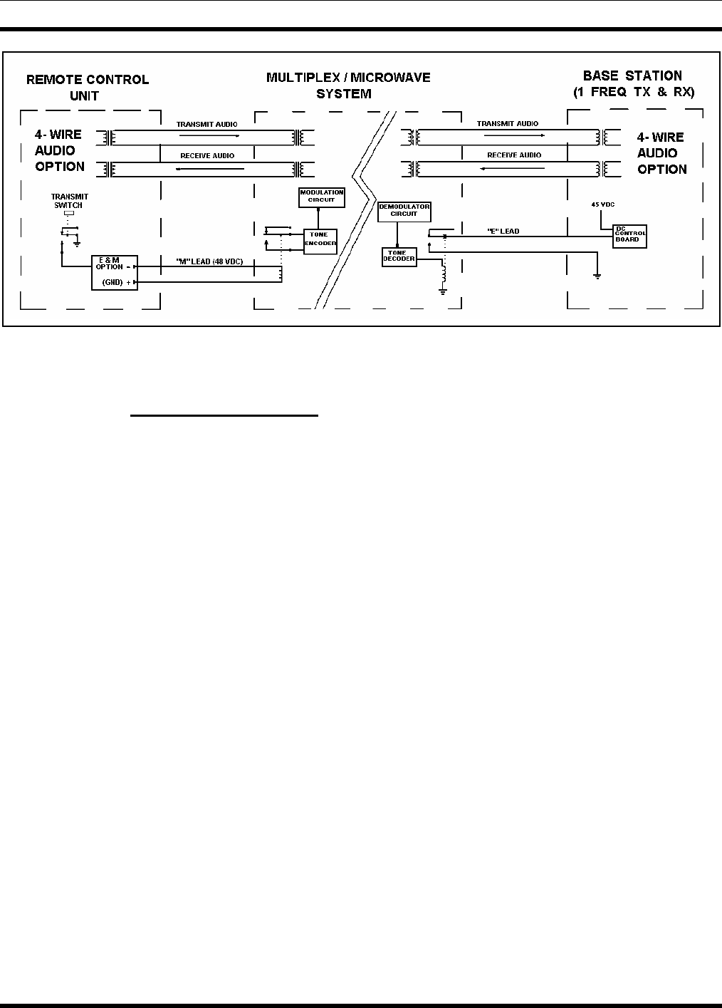
MM102554V1 REV B
46
Figure 7-5: Typical E & M Signaling Application
7.2.2 Type 1 E & M Signaling
E & M Type 1 signaling uses two leads, E and M, which share a common ground path. Type 1 E & M
signaling was originally designed for use with electromechanical switching systems and is not
recommended for use in electronic systems due to the noise induced by the ground path.
Type 1 E & M signaling keys the station remotely by using a contact closure to ground. When this option
is selected, control is exercised by applying a ground to P110 pin 1 (Repeater Hot Standby) on the station
Interface Board or by applying a ground to P5 Pin 16 on the station backplane. This causes the station to
execute a “Channel 1 – Remote PTT” which routes the audio from the Line Input to the transmitter.
7.3 TONE REMOTE INSTALLATION
In contrast with DC systems, where audio level setting is not as critical, it is important that levels in tone
applications be set properly. Failure to do so results in the control function not working properly. For
example, after the installation when the user has gained a little experience, the user may find that they are
not always picking up the function selected. A little extra time spent at the installation will save many
problems of this type later.
This equipment is designed so that the tone control sequence consists of two or three parts. The first part
is the “Secur-it” tone (2175 Hz), which is sent at the highest level for approximately 125 milliseconds.
This is followed by the “Function” tone which is sent at a level 10 dB lower for approximately 40 ms. In
the case of a transmit function, the “Function” tone is followed by 2175 Hz “Hold” tone at a level 30 dB
down from the “Secur-it” tone burst (therefore, it is 20 dB down from the “Function” tone burst). This
tone continues for the duration of the transmit function. The average voice (0 VU) is sent at the same
level as the “Function” tone, therefore, the test tone for the voice is sent at the same level as the “Secur-
it” tone.
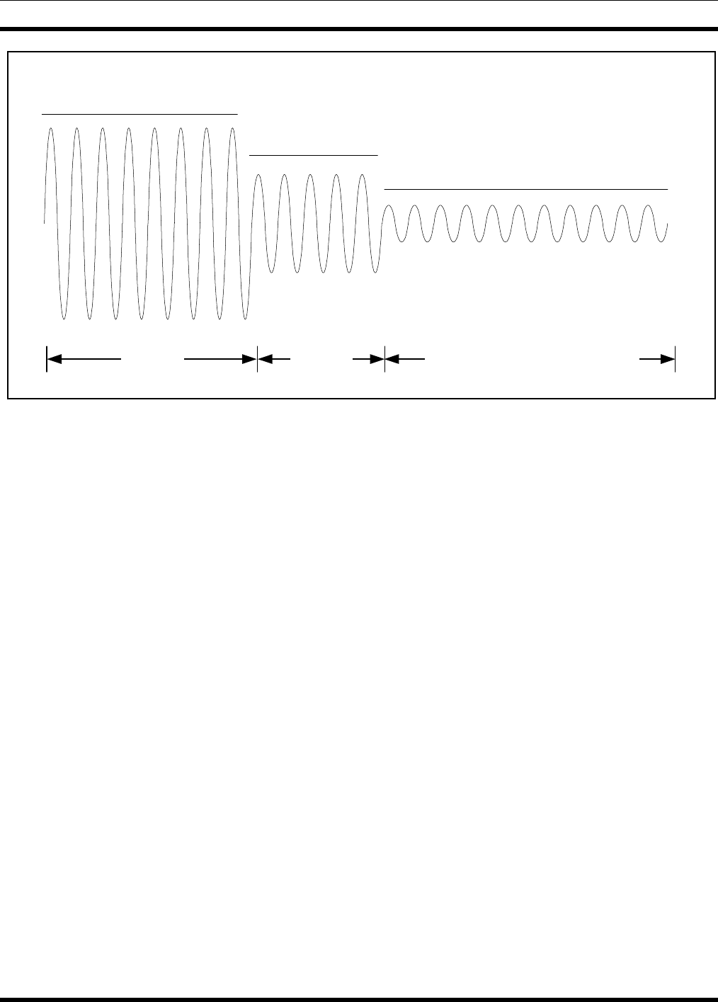
MM102554V1 REV B
47
125 ms 40 ms As long as PTT switch is pressed
2175 Hz SECUR-IT Tone
+10 dB
FUNCTION Tone
0 dB 2175 Hz Transmit HOLD Tone
-20 dB
Figure 7-6: Tone Control Sequence
The “Secur-it” tone must arrive at the base station at no less than -20 dBm. The transmit “Hold” tone
must arrive at the base station at no less than -50 dBm. The test tone for the voice must arrive at the base
station at no less than -20 dBm. Therefore, the limits of system operation are usually established by only
three things:
1. The maximum level at 2175 Hz that the phone company will allow to be sent from the most distant
point in the system. Normally this will not be higher than 0 dBm. In some cases, it can even be less,
or on rare occasions, it can be +5 or +10 dBm.
2. The loss of the circuit at 2175 Hz. Do not forget the long-term variation of up to 4 dB more.
3. The requirement that the “Secur-it” burst must arrive at the base station at no less than -20 dBm.
Normally, most systems will not crowd these limits. However, if the result is a few dB short, consider
adding C-1 conditioning (at an added cost). Resist the natural desire to just turn up the tone sending level
as this will cause improper system operation.
Increasing the level will cause the “Secur-it” tone burst to go into limiting in the phone company
equipment. The limited tone causes the “Secur-it” tone filter in the base station to ring. This will result
in picking up or dropping out functions, which were not selected. NEVER allow the “Secur-it” tone to be
in limiting.
There is an easy way to check and see if the “Secur-it” tone is in limiting. With the phone lines
connected to the equipment at both ends, connect an AC voltmeter across the phone line at the base
station. Arrange to send a burst of “Secur-it” tone long enough to measure the incoming level on the AC
voltmeter. Then arrange to send a burst of 1950 Hz “Function” tone long enough to measure the
incoming level on the AC voltmeter. If the 1950 Hz tone does not arrive 10 dB (1 dB) less than the
“Secur-it” tone, then the “Secur-it” tone is in limiting. It will become necessary to lower the sending
level at the remote controller until it is below limiting.

MM102554V1 REV B
48
If the audio is high enough to cause the telephone equipment to go into limiting, it will cause amplitude
distortion. On a high loss line, the amplitude distortion will cause the “Hold” tone (2175 Hz) to vary and
the transmitter to drop out.
On remote systems using tone control, care must be used when connecting two telephone lines in tandem.
For example, for a base station and two remotes, a phone line is ordered to connect the station to the first
remote, and a second line to connect the second remote to the first remote. The loss of each line is now
added together and the tones from the second remote cannot operate the base station. The installer can
either specify a low loss on each line, or run each line directly to the base station.
A check with the phone company can determine which approach is the least expensive over a period of
time; i.e., an analysis of non-recurring costs versus recurring costs over the expected length of time the
circuit will be used.
7.3.1 Voting System Considerations
A voting system uses a continuous 1950 Hz tone on the telephone line when the receiver is squelched.
This voting tone is normally sent from the station to the voting selector 3 dB lower than the 1000 Hz test
tone level. Most telephone lines have a frequency response, which attenuates the 1950 Hz tone with
respect to a 1000 Hz test tone; therefore, care should be taken to ensure that the correct levels are received
at the voting selector.
If the telephone company will not allow a continuous tone as high as -8 dBm to be sent, then a lower loss
circuit should be requested or C-1 conditioning added.
When ordering phone lines for a voting system, if possible, all lines should be of the same type. Different
telephone line responses will cause the voter to prefer one signal to others.
It is improper system design to have the received signal selection biased by a “poorer” telephone circuit.
Many telephone companies will add pads to build out the lines. If this is considered when the lines are
ordered, it should not be difficult to build all of the lines out to have the same frequency response.
A tone remote control unit can initiate a transmission, listen to received audio, and select or deselect base
station functions. Functions selected by the different available tones can be programmed so that a 1450
Hz “Function” tone, for example, can be used for different functions.
Signaling from a tone remote control unit consists of a high level “Secur-it” tone, followed by the
appropriate medium level “Function” tone (as well as a “Hold” tone if the transmitter is keyed). The
tone control sequence is shown in Figure 7-6.
The “Secur-it” tone is a +10 dB, 2175 Hz tone that is present for 125 milliseconds. The “Secur-it” tone
is followed by a 40 millisecond, 0 dB “Function” tone. The “Function” tone can be followed by a -20
dB, 2175 Hz “Hold” tone if PTT is selected. The “Hold” tone is present as long as the PTT is pressed.
7.3.2 Function Tones
The frequency of the “Function” tone determines the function selected by a tone remote control unit.
“Function” tones range from 1050 Hz to 2050 Hz, and are spaced 100 Hz apart.
The following station functions can be controlled by tone signaling from a remote control unit:
• Repeater Enable (disable)
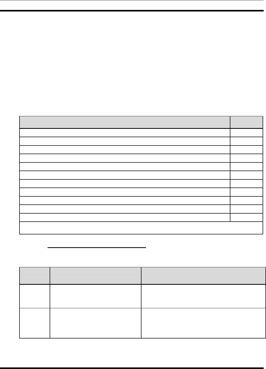
MM102554V1 REV B
49
• Channel Guard Decode Enable (disable)
• Channel Guard Monitor
• Transmit Frequency Selection
• Receive Frequency Selection
• Scan
• Receiver Selection (Auxiliary Receiver selection)
• Auxiliary Output Enable (disable) (Auxiliary Control)
See Table 7-3 for a list of “Function” tones and their corresponding function.
Table 7-3: Tone Control Function and Frequency
FUNCTION TONE
RX Channel Guard Disable (Reset by PTT) 2050 Hz
TX-Freq. No. 1 1950 Hz
TX-Freq. No. 2 1850 Hz
RX-Freq. No. 1 1750 Hz
RX-Freq. No. 2 1650 Hz
Channel Guard Decode On or Repeater Enable* 1550 Hz
Channel Guard Decode Off or Repeater Disable* 1450 Hz
TX-Freq. No. 3 or Aux. Function 1 On 1350 Hz
TX-Freq. No. 4 or Aux. Function 1 Off 1250 Hz
Repeater Enable* 1150 Hz
Repeater Disable* or Scan or Simultaneous Monitor 1050 Hz
* Repeater Enable (disable) is 1150/1050 only when Channel Guard On/Off is present.
7.3.3 Wiring Methods for Tone Remote
Table 7-4: Tone Remote Wire Line Installation Methods
METHOD DESCRIPTION ADVANTAGES OR
DISADVANTAGES
1 Standard two-wire configuration.
Single voice grade pair used for both
control and audio frequencies.
This is the most economical method and simplest to
install. The cost varies depending on local service.
2 Standard four-wire configuration.
One voice grade pair is used for TX
audio and the other pair is used for
RX audio.
This method is also economical. It minimizes
keying clicks in paralleled remotes. Large ground
currents may result in interference with control
functions if remotes are located near sub-stations.
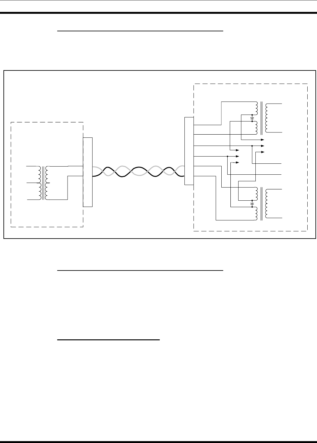
MM102554V1 REV B
50
7.3.4 Installation Method 1 – Two Wire Tone Remote
When the control shelf is used with a two-wire tone remote/console, the remote control pair should be
connected to TB101-3 and TB101-4. Jumpers on P104 and P105 located on the Interface Board are not
required and should be removed.
J101,
J109,
TB101
2
5
3
4
1
6
T101
LINE_A
LINE_B
DC_CNTLR
DC_CNTLR
Telephone Line +
Telephone Line -
Tone Remote Controller
MASTR III ADC T/R SHELF
Interface Board
DC Control +
DC Control -
J104
1
2
3
J105
1
2
3
T102
DPLX_LINE_A
DPLX_LINE_B
Duplex Audio +
Duplex Audio -
2
5
1
6
3
4
Figure 7-7: Tone Remote Installation Method 1
7.3.5 Installation Method 2 - Four Wire Tone Remote
When the control shelf is used with a four wire tone remote/console, the remote control transmit pair
(which modulates the transmitter) should be connected to TB101-2 and -5. The remote control receive
pair (which listens to the receiver) should be connected to TB101-3 and TB101-4.
7.4 T/R SHELF REMOTE CONTROL CONNECTIONS
7.4.1 Interface Board Connections
Telephone line connections may be made on the terminal block (TB101) or with an RJ-11 connector to
J101 or J109. The telephone line cable may be routed through the top rear or bottom rear of the cabinet
(refer to Figure 7-10 and the station Assembly Diagrams). The telephone line connections are shown in
Figure 7-9.
If the system uses remote control, perform the following operations:
1. Make the connections to the Interface Board according to the remote control method described earlier
in this section.
2. Ensure the Remote Control unit is properly installed and configured for the desired control method.
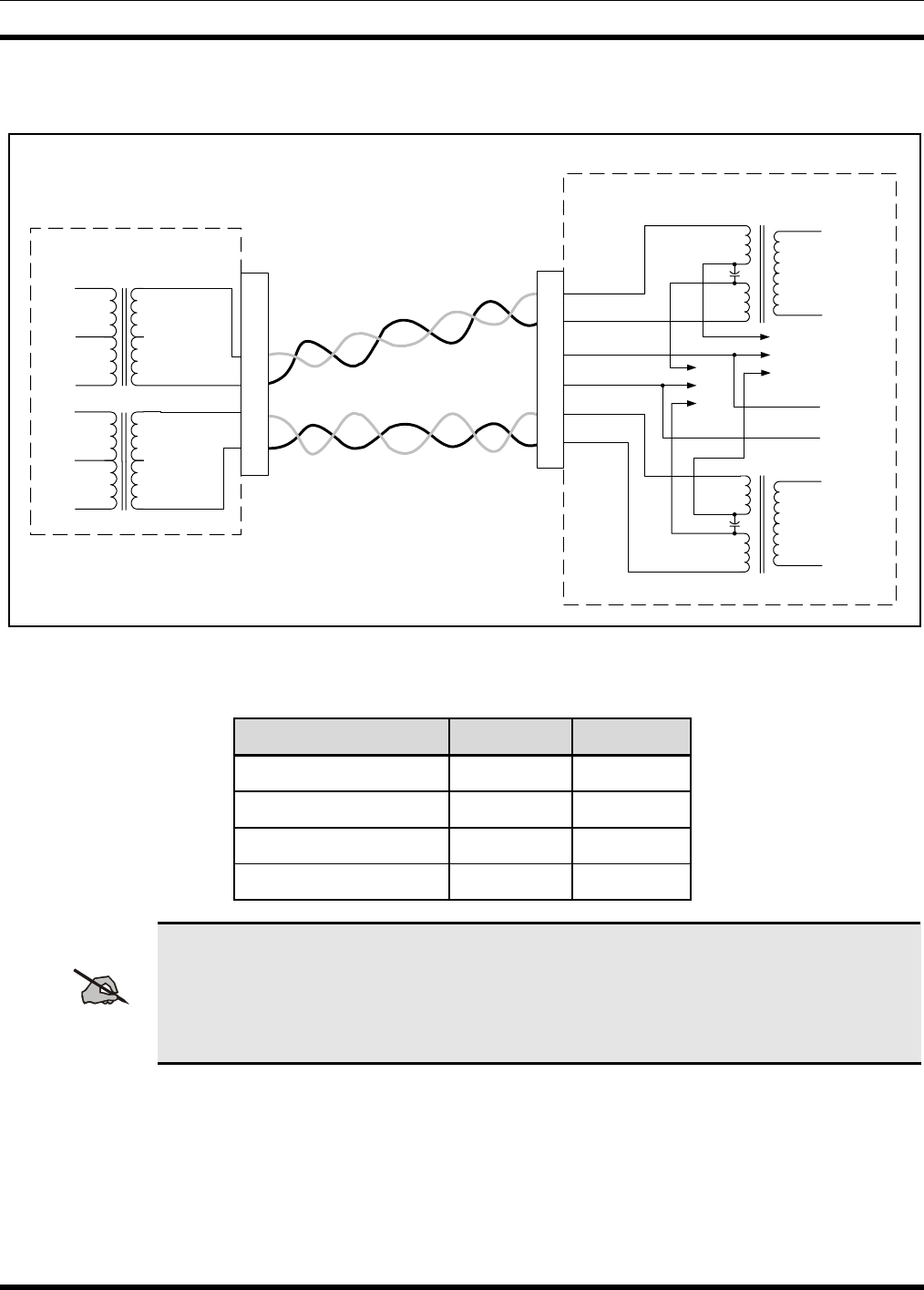
MM102554V1 REV B
51
3. Verify the jumpers on the Interface Board are set for the desired control method (refer to Table 7-5:
Remote Control Jumper Installation).
J101,
J109,
TB101
T101
LINE_A
LINE_B
DC_CNTLR
DC_CNTLR
Telephone Line +
Telephone Line -
Tone Remote Controller
MASTR III ADC T/R SHELF
Interface Board
DC Control +
DC Control -
J104
1
2
3
J105
1
2
3
T102
DPLX_LINE_A
DPLX_LINE_B
Duplex Audio +
Duplex Audio -
2
5
1
6
3
4
TX AUDIO
to T/R Shelf
1
6
3
4
2
5
RX AUDIO
from T/R Shelf
Figure 7-8: Tone Remote Installation Method 2
Table 7-5: Remote Control Jumper Installation
CONTROL METHOD P104 P105
DC Control, 2-wire 1 & 2 1 & 2
DC Control, 4-wire 2 & 3 2 & 3
Tone Control None None
E & M None None
NOTE
The pin connections on TB101 are wired in parallel on the Interface Board with the
corresponding pins on modular connectors J101 and J109. J101 and TB101 are accessible
from the top of the T/R Shelf Interface Board. If the top of the Interface Board is
inaccessible, then use J109, which is accessible from the rear of the cabinet. Connectors
J101 and J109 are RJ-11 6-pin modular jacks.
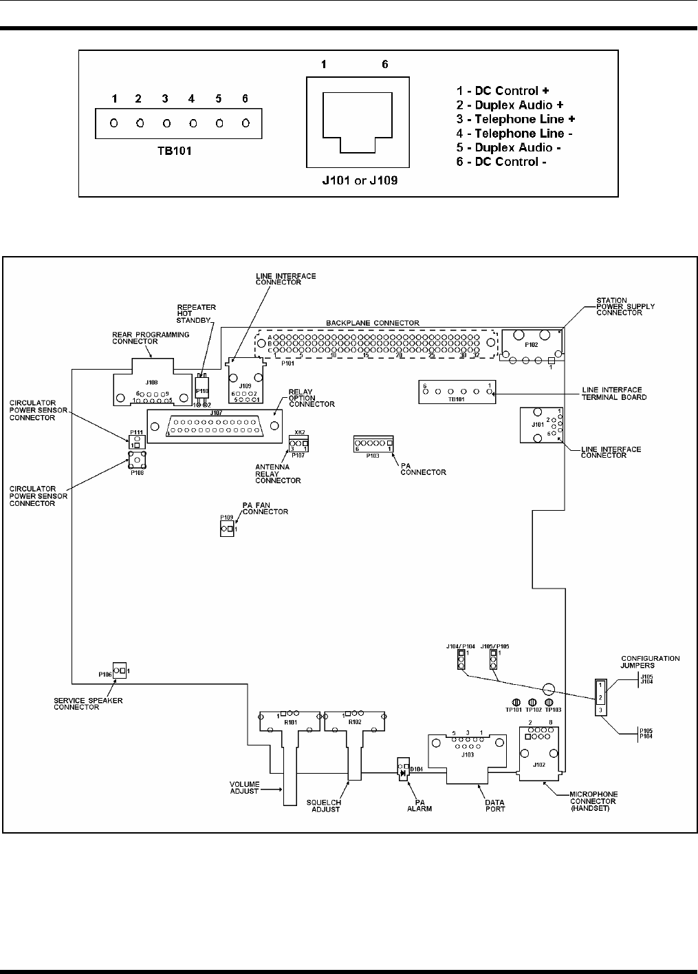
MM102554V1 REV B
52
Figure 7-9: T/R Shelf Telephone Line Connections
Figure 7-10: T/R Shelf Interface Board Connections
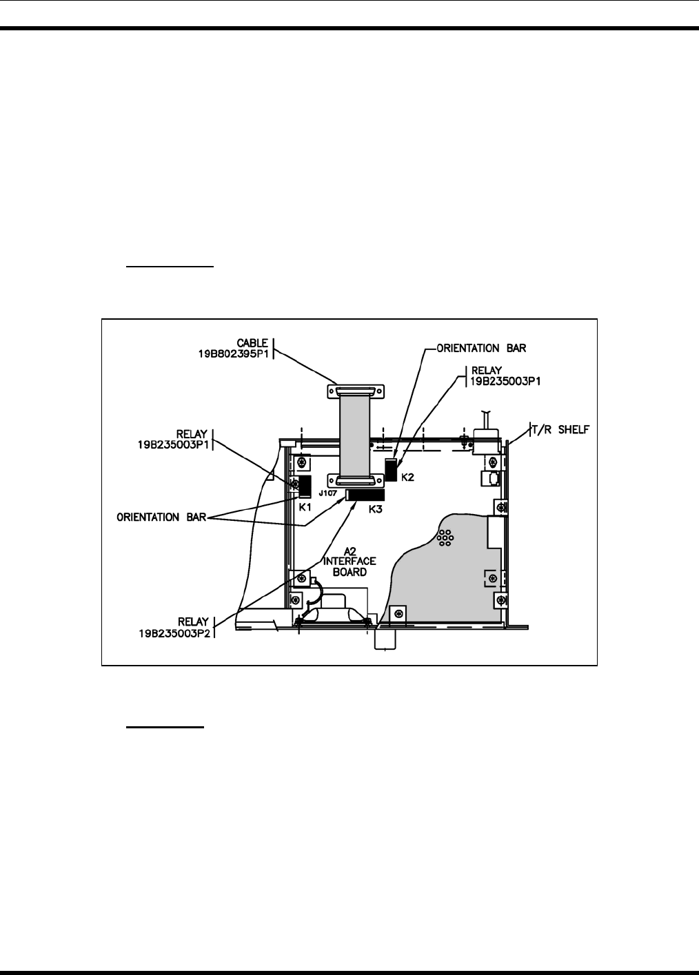
MM102554V1 REV B
53
7.5 SQUELCH OPERATED RELAY OPTION (SXSU3D)
This section provides additional information for installing the Squelch Operated Relay (SOR) option
SXSU3S. The option kit includes the following items:
• K3, SOR – 19B235003P2
• K1, AUX1 Relay - 19B235003P1
• K2, AUX1 Relay - 19B235003P1
• DB25 Extension Ribbon Cable – 19B802395P1
7.5.1 Installation
To install the kit, insert the relays and the ribbon cable on the Interface Board as shown in Figure 7-11.
Figure 7-11: Squelch Operated Relay Option Installation
7.5.2 Operation
The SOR (K3) contains four form "C" contacts and is rated for 2 amps at 20 VDC. The relay operates
under control of signal RX_1_MUTE, which is derived from CAS, with the coil of K3 being picked up by
transistor switch Q110. (Refer to the SOR diagrams in Figure 7-12.)
AUX1 relay (K1) and AUX2 relay (K2) each contain two form "C" contacts and operate under remote
control. When AUX1 function is started via remote control, the system microprocessor sets signal
RXF3/AUX1 to logic high which turns on transistor switch Q112 picking up the coil of K1. When
AUX2 function is started, the system microprocessor sets bit 4 of output register U106 high, turning on
transistor switch Q111 picking up the coil of K2. When the AUX functions are stopped, the control bits
are toggled, and the relay coil drops out.
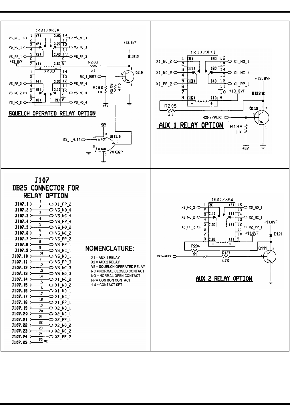
MM102554V1 REV B
54
Figure 7-12: Squelch Operated Relay Option Connections

MM102554V1 REV B
55
7.6 SHARED REPEATER PANEL INSTALLATION
This section provides information for installing and configuring the MASTR III Conventional ADC Base
Station for use with a Shared Repeater Tone Panel.
7.6.1 General
The MASTR III ADC Base Station may be used as a “community” or “shared” repeater. This allows
multiple users to share a common repeater. However, a common or shared repeater allows anyone
transmitting on frequency and in some cases undesirable noise to pass through or unsquelch the system.
This reduces the system availability and is annoying to radio users. To keep the nuisance listening to a
minimum, a sub-audible tone signaling system, the Continuous Tone Coding Squelch System (CTCSS)
and the Continuous Digital Coded Squelch System (CDCSS or DCS) were developed. In the MASTR III
Base Station these squelch systems are referred to as Channel Guard (CG) and Digital Channel Guard
(DCG). When used, an encoded sub-audible tone is sent over the air to the receiving station, which, in
turn, has a decoder. The decoder doesn't let any sound through to the speaker until it hears the specific
tone or code it was programmed to listen for. In the repeater system, decoding a given tone or code by
the receiver results in encoding the tone or code along with the repeated audio on the repeater transmit
frequency.
The MASTR III ADC Base Station can be programmed for multi-channel scanning with different CG
tones (CTCSS) or DCG (CDCSS) codes. Programming the station requires using the MASTR III
Programmer, (TQS3353) or MSEDIT (TQ0619) on site and scanning beyond two channels is impractical
because of the time involved.
One solution to making a MASTR III Base Station into a “community” repeater is to use an external
“shared” repeater panel or multi-tone CTCSS device. The repeater panel allows the system operator to
program the repeater and to remotely add or remove users. Some repeater panels add other features, such
as; audio processing, courtesy beeps, alarms, and timing and billing.
7.6.2 Repeater Panel Interface
The MASTR III ADC Base Station does not have a single connector for interfacing between the base
station and the repeater panel. As a result, it is necessary to fabricate a special cable with three
connectors or to solder wires directly to the backplane. The field engineer or installer should decide
which method is most practical. The most reliable and least expensive method is to solder the interface
wires to the connections on the backplane. However, a specially fabricated cable harness has definite
advantages in time saved when installing or troubleshooting multiple repeaters.
The following tables (Table 7-6 through Table 7-8) can be used to identify the signal lines that interface
with the repeater panel and where they can be found on the MASTR III ADC Base Station backplane (see
Figure 7-13 for Backplane connector locations).
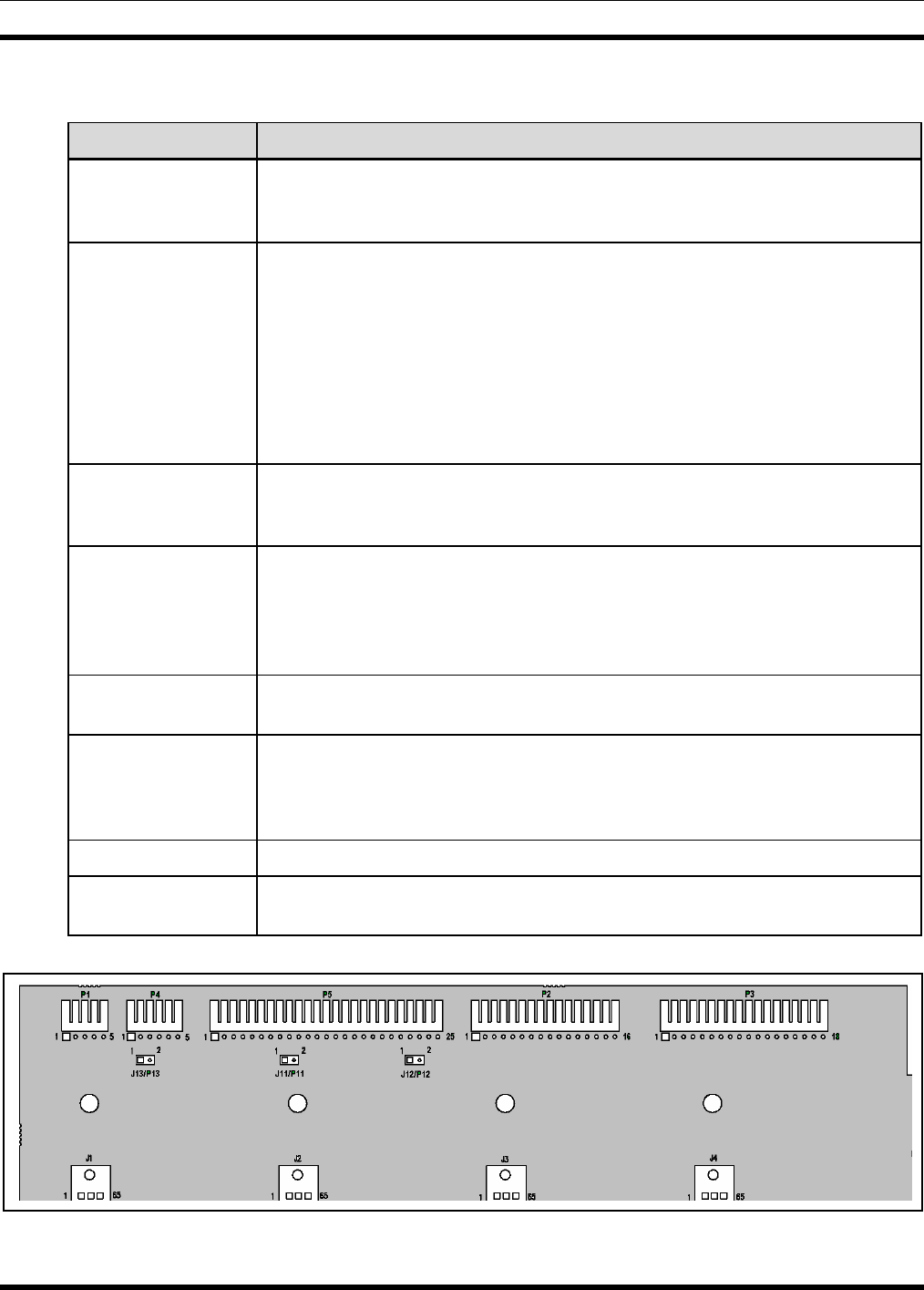
MM102554V1 REV B
56
Table 7-6: Community Repeater Interface Signal Lines
SIGNAL NAME DESCRIPTION
RCVR_VOL/SQ_HI The receiver volume and squelch high line is the non de-emphasized output
from the RX IF board. The level for standard deviation is 1-Vrms. Expect
about 170 mVrms of CTCSS level when modulated at 15% system deviation.
SYS_VOL/SQ_HI The System Volume Squelch High lead is normally the same point as the
RCVR_VOL/SQ_HI. Jumper J11 must be removed from P11 on the backplane
to separate the two leads. The SYS_VOL/SQ_HI is the return path of audio to
the station. Removing the jumper and using this lead is undesirable.
Processing of speech audio will be performed by the system module and any
further external processing will complicate and sometimes cause problems.
Reasons for using this circuit however may include squelch tail elimination,
adding courtesy tones, or muting repeated audio. The overall gain of any audio
processing should be unity and with a flat frequency response.
CAS Carrier Activity Sensor (CAS) indicates the condition of the noise squelch
circuit. A TTL level high (5 Volts) indicates an on channel carrier while a logic
low indicates a lack of carrier.
EXT_LSD External Low Speed Data lead goes to the system module. There the lead is
switched to the high side of the CG electronic potentiometer. The level of the
encode CTCSS or CDCSS should be set to between 0.5 and 1 Vrms. The final
deviation level will be set by the CG electronic potentiometer during station
alignment.
REPEAT_PTT_IN Logic low or ground on this lead will key the transmitter and route audio from
the SYS_VOL/SQ_HI and EXT_LSD leads to the transmitter audio circuits.
A+ Unfiltered power coming from the main station power supply. This point is not
regulated to a specific value. Its voltage may vary with the load of the station,
but usually it makes a good point for providing A nominal 12 VDC to the
station. Do not use the +12 volt circuits to provide power to external devices.
DGND Same as the chassis ground of the station. Can be use for DC return path.
AGND Analog ground. Can be used to ground cable shields. If hum exists, add or
remove the shield from the AGND to eliminate the problem.
Figure 7-13: T/R Shelf Backplane Connections
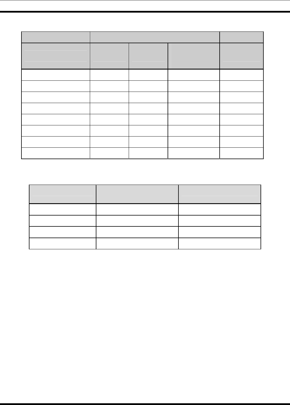
MM102554V1 REV B
57
Table 7-7: MASTR III Backplane Connections for Community Repeater Interface
MASTR III BACKPLANE CONNECTIONS
SIGNAL NAME P2
(GETC) P3
(GETC) P5
(VOICE
GUARD)
REPEATER
PANEL
RCVR_VOL/SQ_HI P2.5 P5.10
SYS_VOL/SQ_HI P5.8
CAS P3.5 P5.17
EXT_LSD P3.14
REPEAT_PTT_IN P2.13
A+ P2.1 P5.1
DGND P2.2 P3.10 P5.12
AGND P5.4
Table 7-8: Mating Connector Part Numbers
NOMENCLATURE M/A-COM PARTS
NUMBER MOLEX PART NUMBER
J2 (connect to P2) 19A700041P42 22-01-2165
J3 (connect to P3) 19A700041P44 22-01-2185
J5 (connect to P5) 19A700041P50 22-01-2155
Pins (individual) 19A704779P26 08-55-0101

MM102554V1 REV B
58
8. STATION TEST AND ALIGNMENT PROCEDURES
8.1 INTRODUCTION
This chapter provides instructions for testing and aligning the MASTR III Conventional or P25 Base
Station. The base station is normally pre-aligned at the factory and ready to install. However, after initial
installation and prior to placing the equipment into operation, it should be rechecked to ensure it is
operating properly and meets the required specifications.
These procedures assume the receiver and transmitter modules have been previously tuned and aligned
and should be used whenever a module or system component is repaired or replaced.
8.2 GENERAL
The MASTR III ADC Base Station comes pre-programmed and ready to install, the only adjustments
needed are the required Line Output Level, the Line Input Level necessary to produce Standard
Deviation, and the Line Cancellation for 2-wire Tone Remote Orientation. These adjustments can be
made using the PC Programming option TQS3353, the Utility PC software TQ0619, or with the Utility
Handset SPK9024.
The rated system deviations are as follows:
• 5.0 kHz Standard (25 kHz IF)
• 4.0 kHz NPSPAC
• 2.5 kHz Narrow (12.5 kHz narrowband)
• 2.8 kHz P25
8.3 SUPPORT EQUIPMENT REQUIRED
The following equipment and software may be require to perform the MASTR III ADC Base station
alignment and tests:
8.3.1 Hardware
Table 8-1: Hardware Requirements
DESCRIPTION MODEL NUMBER PURPOSE
Communication Test Set IFR 1200, 1500 or
equivalent System test and alignment
Directional Coupler Narda 3020A or
equivalent Test output power
RF Coaxial Load Resistor Bird 8235 Test and alignment
RF Power Meter with 3%
measurement accuracy Boonton
4220A/51033er or
equivalent
Test output power
Attenuator, 10 dB, 100 W Bird 8343-100 Test and alignment
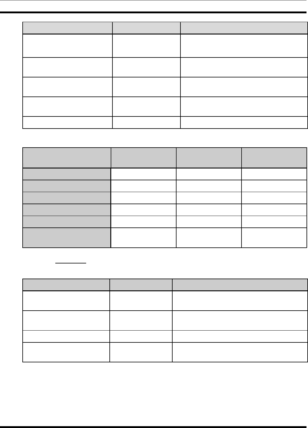
MM102554V1 REV B
59
DESCRIPTION MODEL NUMBER PURPOSE
Extender boards 188D5338G1
188D5338G2
Use to extend System and Power Modules
Use to extend RF Modules
RF Module Test Fixture TQ0650 Individually test, align, and troubleshoot RF
modules off station
PC Computer See Table Test, alignment and station personality
programming
RS-232 Programming Cable TQ3356 or equivalent
DB9(M) to DB9(F) Connect PC computer to T/R Shelf
Utility Handset SPK9024 Test and alignment
Table 8-2: PC Computer Requirements
Windows® NT 4.0
(Service Pack 4) Windows 2000 Windows XP
Processor Speed Pentium II 90 MHz Pentium II 133 MHz Pentium II 233 MHz
RAM for Windows 128 Megabytes 128 Megabytes 128 Megabytes
Hard Drive Space 160 Megabytes 160 Megabytes 160 Megabytes
Drives CD-ROM CD-ROM CD-ROM
Ports 1 Serial 1 Serial 1 Serial
Microsoft Internet
Explorer Version 5.01 or higher Version 5.01 or higher Version 5.01 or higher
8.3.2 Software
Table 8-3: Software Requirements
DESCRIPTION PART NUMBER PURPOSE
MASTR III Programmer TQS3353 Test, alignment and station personality
programming
MASTR Utility Programmer
(MASTRUTL) TQ0619 Test and alignment (subset of MIII Programmer
TQS3353)
Utility Handset SPK9024 Test and alignment
DSP Module Programmer TQS3413 DSP Module configuration and personality
programming
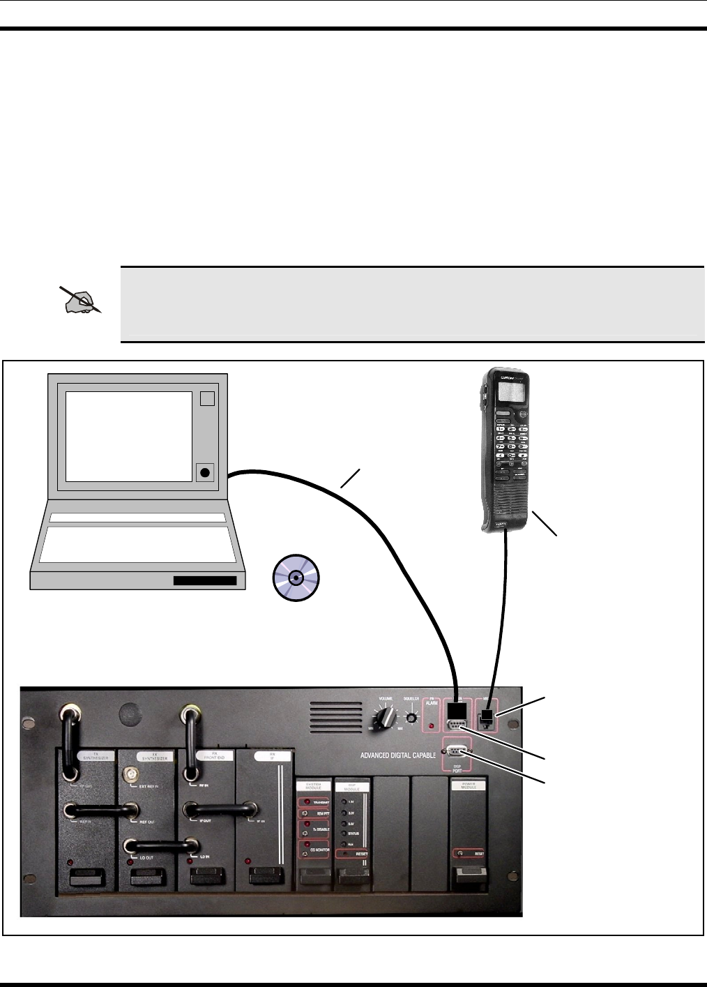
MM102554V1 REV B
60
8.4 STATION CONFIGURATION
Use the following procedures when setting up the station using a Personal Computer (PC). If the Utility
Handset is plugged into the MIC connector, it must be removed prior to resetting the system and using the
PC Programming software. Levels may be adjusted using the MASTR III Utility program TQ0619
(MASTRUTL) supplied with the PC Programming package TQS3353.
1. Ensure proper connections are made to receive and transmit antenna(s).
2. Apply power to the equipment.
3. Connect the PC computer’s serial COM port to the T/R Shelf DATA PORT using the TQ3356
Interconnect cable (19B801348P2) or equivalent. Refer to Figure 8-1.
NOTE
The base station may also be programmed from the rear by connecting the computer to the
rear Data Port connector (J108) located on the T/R Shelf Logic Board shown in Figure 7-10.
TQ3356 or
RS-232 Cable
SPK2094
Utility Handset
MIC
(Note: handset and PC
cannot be connected to
shelf at the same time)
DATA Port
DSP Port
Laptop computer
Software
MIII Programmer - TQS3353
MIII Programmer Utility- TQ0619
Figure 8-1: MASTR III Programmer Connections
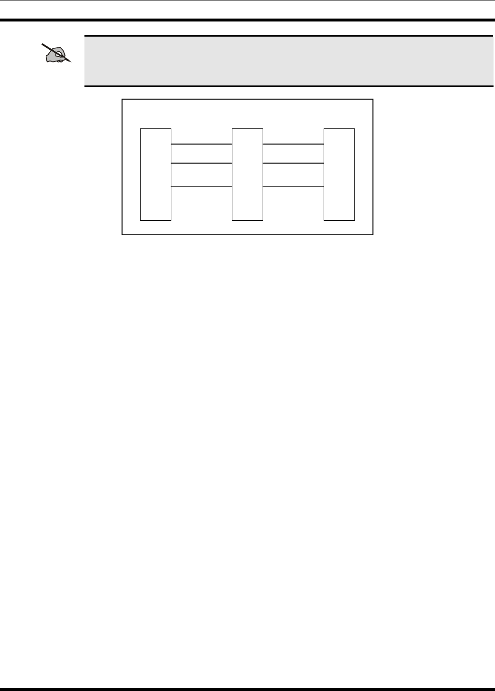
MM102554V1 REV B
61
NOTE
If the computer has a 25-pin connector instead of a 9-pin serial connector, an adapter must
be used. The adapter may be either purchased or locally manufactured. Making your own
requires only three wire connections (Figure 8-2).
Pin 2
Pin 3
Pin 7
Pin 2
Pin 3
Pin 5
Pin 2
Pin 3
Pin 5
DB9 (M) DB9 (F)DB25 (M)
PGM TXD
PC PGM RXD
GND
Figure 8-2: DB9 to DB25 Adapter Cable
4. Run the TQS3353 software and enter M3 to start the MASTR III program.
5. Initiate a RESET (on the Power Module) before programming starts.
6. The SQUELCH and VOLUME adjustments should be made for proper operation. Unsquelch the
receiver by turning the SQUELCH adjustment counter-clockwise. (If your base station has Channel
Guard, also activate the CG switch.) Verify that unsquelched noise is going to the speaker by
increasing the VOLUME (clockwise). Adjust the SQUELCH pot for critical squelch (squelch just
closes).
7. Verify the current personality or create a new personality as required. Do not change Pot settings.
8. Following the initial setup, the MIC port may be used for one of the following purposes:
a. Connecting the local microphone equipped with a modular connector.
b. Connecting the multi-purpose Utility Handset.
8.5 STATION ALIGNMENT
Alignment of the MASTR III base station was performed prior to shipment. The factory assumed the
following characteristics:
1. There is no loss or gain for repeated audio deviation.
2. If a remote exists, it is connected to the base station through a telephone line with 10 dB of loss.
3. The base station drives the line output at -10 dBm with nominal receive deviation.
The base station should deliver –10 dBm to the line with a signal applied with standard 3 kHz deviation.
A –10 dBm audio signal applied to the Station Line In should result in transmitter deviation of 3 kHz.
These values may be altered by following one of the alignment procedures as provided. For minor
adjustments, you may want to adjust only one or two digital potentiometers or leave the setting as set. In
any case, it is important to carefully examine the Alignment Diagram (Figure 8-3).
MM102554V1 REV B
62
NOTE
It is a good idea to record the potentiometer settings on paper, until you’re familiar with all
the digital potentiometer setting process.
Figure 8-3 shows the relationship of the alignment pots in the station:
ADJUSTMENT MSEDIT/MASTRUTL POT NAME
CG Channel Guard
CP DSP Compressor Gain
CT Compressor Threshold
DC Line Cancellation
DLI DSP Line In
LI Line Input
LO Line Out
PA PA Power
RG Repeater Gain
TX Transmit
NOTE
Refer to the Software Release Notes (SRN’s) specific to release of software and hardware
installed in this system for additional details on test setup and jumpers.
CAUTION
Only qualified field service technicians should perform these procedures. Each test has step-
by-step procedures, along with visual aids when necessary, to check the performance or make
alignment adjustments if needed to the individual system elements.
Table 8-4: Digital Potentiometer Settings
LO
POT DC
POT LI
POT DLI
POT CP
POT CT
POT RG
POT TX
POT CG
POT
Line
Out DSP Line
Cancellations Line
In DSP
Line In DSP
Compressor
Gain
Compression
Threshold Repeater
Gain Transmit Channel
Guard
HANDSET
NUMBER 1 5 3 6 7 2 2 2 1
POT PAGE
(Note 1) P_1 P_1 P_1 P_1 P_1 P_2 P_3 P_1 P_1
HANDSET
DISPLAY P LO P DC P LI P DI CP CT RG P TX P CG
DEFAULT
VALUES 45 75 (2W)
0 (4W) 0 34 (2W)
28 (4W) 1023 1890 1023 127
150* 123
0*
*No Channel Guard
NOTES: 1) Refer to Handset manual, LBI-38599, for instructions on page selection.
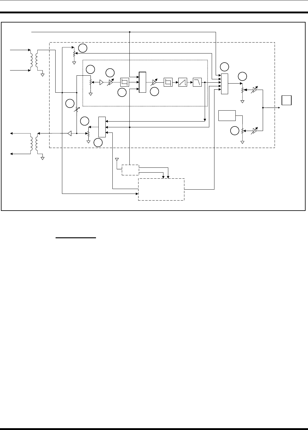
MM102554V1 REV B
63
LINE
IN
LINE
OUT
TB101-2
TB101-5
TB101-3
TB101-4
M
U
X
CP
CT
M
U
XRG
DSP Board
PRE-
EMPH POST LIM
FILTER
LIM M
U
X
MIC HI
TX
U36
CG
U35
TX AUDIO HI
EXT
HSD
RCVR
VOL SQ HI
TO
PA
DLI
U15
LO
U36
CG
Generator
DSP Module
U14
455 kHz IF
MDM Line TXD
MDM Line RXD
System Module
LI
U35
DC
U12
U15
Figure 8-3: MASTR III Conventional Base Station Alignment Controls
8.5.1 Preparation
Unless otherwise stated, all adjustments and alignments in this section are to be made using the MASTR
III PC Programming Utility Software (TQ0619). Tests may also be made using the Utility Handset
(SPK9024). Refer to the Utility PC Programmer Manual (LBI-38540) or the Utility Handset Manual
(LBI-38599) if necessary.
Perform the following steps before starting the alignment procedure:
1. Perform a controlled power up if station is not on. Check equipment for any abnormal indications
2. On stations that are assembled less MASTR III power supplies, supply adequate DC power to the
station from an external power supply. Adjust the input voltage to the PA to 13.4 ±0.3 VDC
(26.0 ±0.3 VDC for the EA101292 Power Amplifier).
3. Connect the signal generator to the antenna system jack in all but repeater combinations or duplex
stations. In repeater stations, a separate Receive antenna jack is provided.
4. For multi-frequency stations, activate the TX Disable switch on the System Module and select the
desired receive frequency using the PC.
5. Adjust the SQUELCH and VOLUME for proper operation. Unsquelch the receiver by turning the
SQUELCH adjustment counter-clockwise. Verify that unsquelched noise is going to the speaker.
Adjust the volume if needed (clockwise to increase level).
6. Terminate Line Input (TB101-2, 5), and Line Output (TB101-3, 4), with 600 ohms.

MM102554V1 REV B
64
7. Plug the Utility PC Programmer cable into the DATA connector, or Utility Handset cable into the
MIC jack, both located on the front of the T/R Shelf. (Refer to Figure 8-1.)
NOTE
The Utility Handset and the Utility Programmer cannot be connected to the T/R Shelf at the
same time.
8.5.2 Station Pot Defaults
Adjust the following Station level control POT settings to the value indicated:
• Transmit Limiter (TX) 150
• Repeater Gain (RG) 1023
• Compressor Threshold (CT) 32767
• Compressor Gain (CP) 1023
• DSP Line Input (DI) 100
• Line Input (LI) 0
• DC 75
8.5.3 Channel Guard (CG) Pot
The Channel Guard (CG) pot on conventional systems, sets the deviation level
If the station is not programmed for Channel Guard, set the CG pot to zero (0).
For stations programmed for channel guard encode, perform the following steps:
1. Connect the base station TX Synthesizer RF OUT (J2) to the Communications Test Set ANT IN.
2. Setup the Communication Test set to measure deviation.
3. Ensure the base station receiver is squelched for this test since RX audio will be routed to the
transmitter.
4. Execute a REMOTE PTT by pushing the System Module REM PTT switch to the up position. This
keys the transmitter.
5. Measure the transmitter deviation. Deviation must be within ±25 Hz of the value listed in Table 8-5.
6. Adjust the Channel Guard deviation pot (CG) for the appropriate deviation as listed in Table 8-5.
7. Unkey the transmitter by releasing the REMOTE PTT.
8. Repeat this procedure for each frequency with channel guard.
9. Disable channel guard decode for the remainder of the station alignment.
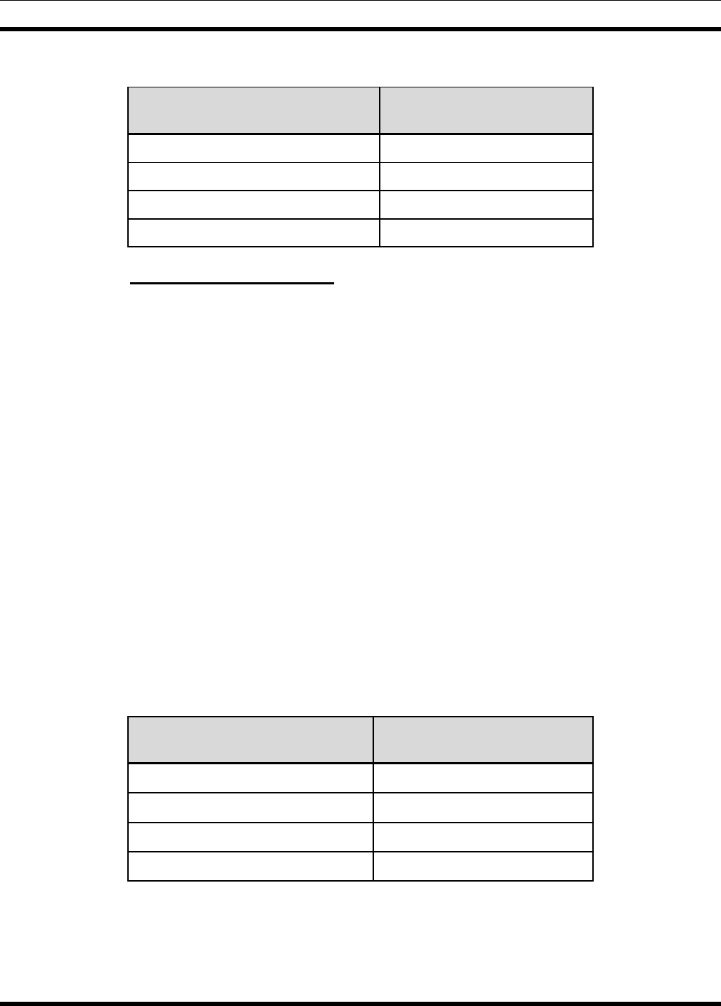
MM102554V1 REV B
65
Table 8-5: Channel Guard Deviations
SYSTEM TYPE CHANNEL GUARD
DEVIATION
Standard (25 kHz IF) 750 (750 Hz)
NPSPAC 600 (600 Hz)
Narrow (12.5 kHz narrowband) 500 (500 Hz)
P25 500 (500 Hz)
8.5.4 Transmit Limiter (TX) Pot
The Transmit Limiter (TX) pot adjusts the limit of deviation for both Line In and Repeat Audio.
1. Preset the following pots as indicated:
• RG (Repeater Gain) - 1023
• CT (Compressor Threshold) - 5000
• CP (Compressor gain Pot) - 1023
• DLI (DSP Line Input) - 100
2. Apply a 1000 Hz tone at 0 dBm (775 mVrms) to the line input (TB101-2 and TB101-5).
3. Execute a REMOTE PTT by placing the System Module REM PTT switch to the up position. This
keys the transmitter.
4. Measure the transmitter deviation. The deviation maximum value must be within ±100 Hz of the
value listed in Table 8-6
5. Adjust the Transmit Limit pot (TX) for the appropriate maximum deviation as listed in Table 8-6.
6. Unkey the transmitter by releasing the REMOTE PTT.
7. Remove the input signal from line input.
8. Repeat this procedure for each channel.
Table 8-6: TX Limiter Max Deviation
SYSTEM TYPE TRANSMIT MAXIMUM
DEVIATION
Standard (25 kHz IF) 4.5 kHz ±100 Hz
NPSPAC 3.6 kHz ±100 Hz
Narrow (12.5 kHz narrowband) 2.250 kHz ±100 Hz
P25 2.250 kHz ±100 Hz
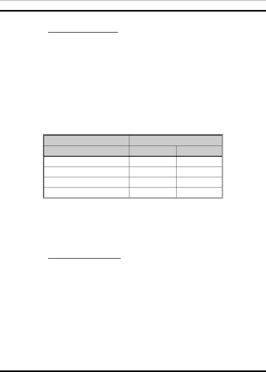
MM102554V1 REV B
66
8.5.5 Repeater Gain (RG) Pot
The Repeater Gain (RG) pot is set so that the deviation of the unsquelched receiver audio results in the
transmitted audio having the same deviation.
If this is not a repeater station, leave the RG pot at 1023.
For a repeater station, perform the following steps to set the RG pot:
1. Set the Communication Test set for an “on-frequency” RF signal modulated by a 1 kHz tone at 60%
of rated system deviation (see Table 8-7).
2. Connect the Test Set RF OUT to the Receiver Front End Module RF IN connector (J2).
3. Execute a REMOTE PTT by placing the System Module REM PTT switch to the up position. This
keys the transmitter.
Table 8-7: 60% of System Deviation
SYSTEM TYPE 60% DEVIATION
CG Disabled CG Enabled
Standard (25 kHz IF) 3.00 kHz 3.75 kHz
NPSPAC 2.40 kHz 3.00 kHz
Narrow (12.5 kHz narrowband) 1.50 kHz 2.00 kHz
P25 1.50 kHz 2.00 kHz
4. Measure the transmitter deviation. Verify the transmitted tone is 1 kHz and adjust the Repeater Gain
(RG) pot for the required deviation listed in Table 8-7 ±100 Hz.
5. Unkey the transmitter by releasing the REMOTE PTT.
6. Remove the input signal from the receiver.
7. Repeat this procedure for each channel.
8.5.6 DSP Line Input (DLI) Pot
The DSP Line Input (DLI) pot adjusts the signal level going to the System Module DSP board.
If this is not a remote station, set the DLI pot to zero (0).
For a remote station, perform the following steps to set the DLI pot:
1. Apply a 1000 Hz tone at -10 dBm (245 mVrms) to the line input (TB101-2 and TB101-5).
2. Execute a REMOTE PTT by setting the System Module REM PTT switch to the up position. This
keys the transmitter.
(This level is the function tone level, and is usually -10 dBm across 600 ohms, or 245 mVrms. This
level MUST be 10 dBm below the "maximum system audio level" even if your actual secur-it tone
and function tone are at the same level.)
3. Adjust the DSP Line In DLI Pot for 60% of maximum system deviation if operating with
compression. (Table 8-8).

MM102554V1 REV B
67
Table 8-8: Deviation For Setting Line In Pot With Compression
SYSTEM TYPE DEVIATION FOR SETTING LINE
IN POT WITH COMPRESSION
CG Disabled CG Enabled
Standard (25 kHz IF) 2.80 kHz 3.55 kHz
NPSPAC 2.25 kHz 2.85 kHz
Narrow (12.5 kHz narrowband) 1.40 kHz 1.90 kHz
P25 1.40 kHz 1.90 kHz
4. Unkey the transmitter by releasing the REMOTE PTT.
5. Remove the input signal from the line input.
6. Repeat this procedure for each channel.
8.5.7 Compressor Gain (CP) Pot
The DSP Compressor (CP) Pot is used to indicate the setting, which determines the level of line input
voltage that will lead to compression. For remote systems using the DSP Compressor (all tone remote
systems use the DSP Compressor), this field should be set so that nominal line input audio results in
output audio, which is at rated (see Table 8-9).
If not a remote station set the CP pot to zero (0).
For a remote station, perform the following steps to set the CP pot:
1. Apply a 1000 Hz tone at -10 dBm (245 mVrms) to the line input (TB101-2 and TB101-5).
2. Execute a REMOTE PTT by switching the System Module REM PTT switch to the up position. This
keys the transmitter.
3. Measure the transmitter deviation. Adjust the Compressor Gain (CP) pot for the required deviation
listed in Table 8-9 ±100 Hz.
4. Unkey the transmitter by removing the REMOTE PTT.
5. Remove the input signal from the line input.
6. Repeat this procedure for each channel.
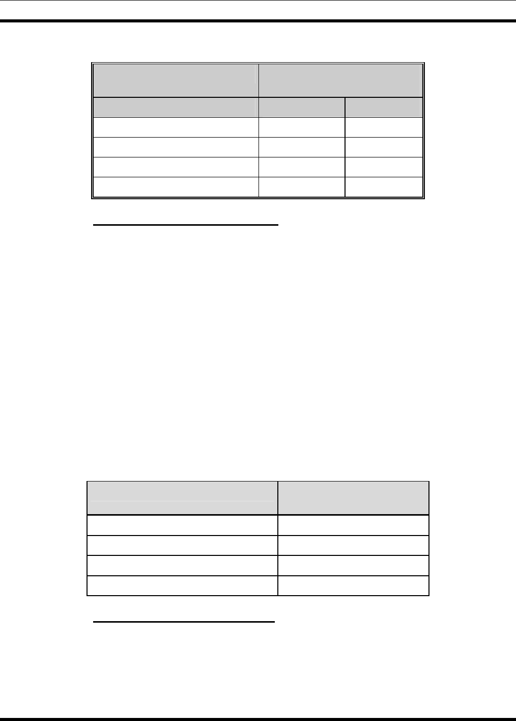
MM102554V1 REV B
68
Table 8-9: Deviation for Setting Compressor Gain Pot
SYSTEM TYPE DEVIATION FOR SETTING
COMPRESSOR GAIN POT
CG Disabled CG Enabled
Standard (25 kHz IF) 3.00 kHz 3.75 kHz
NPSPAC 2.40 kHz 3.00 kHz
Narrow (12.5 kHz narrowband) 1.50kHz 2.00 kHz
P25 1.50 kHz 2.00 kHz
8.5.8 Compressor Threshold (CT) Pot
The Compressor Threshold (CT) pot adjusts the maximum signal level appearing at the output of the
compressor
If this is not a remote station, set the CT pot to zero (0).
For a remotely controlled station, perform the following steps to set the CT pot:
1. Apply a 1000 Hz tone at 0 dBm (775 mVrms) to the line input (TB101-2 and TB101-5).
2. Execute a REMOTE PTT by switching the System Module REM PTT switch to the up position. This
keys the transmitter.
3. Measure the transmitter deviation. Adjust the Compressor Threshold (CT) pot for the required
deviation listed in Table 8-10 ±100 Hz.
4. Unkey the transmitter by removing the REMOTE PTT.
5. Remove the input signal from the line input.
6. Repeat this procedure for each channel.
Table 8-10: Compressor Threshold Deviation
SYSTEM TYPE COMPRESSOR
THRESHOLD DEVIATION
Standard (25 kHz IF) 4.00 kHz
NPSPAC 3.20kHz
Narrow (12.5 kHz narrowband) 2.00 kHz
P25 2.00 kHz
8.5.9 DSP Line Cancellation (DC) Pot
The DSP Line Cancellation (DC) pot is used to specify 2-wire system settings for tone remote
configurations. This separates the T/R Shelf’s line output audio from the line input audio.
For stations using 2-wire tone remote control, set the DC pot to 75.
In all other configurations, set the DC pot to zero (0).
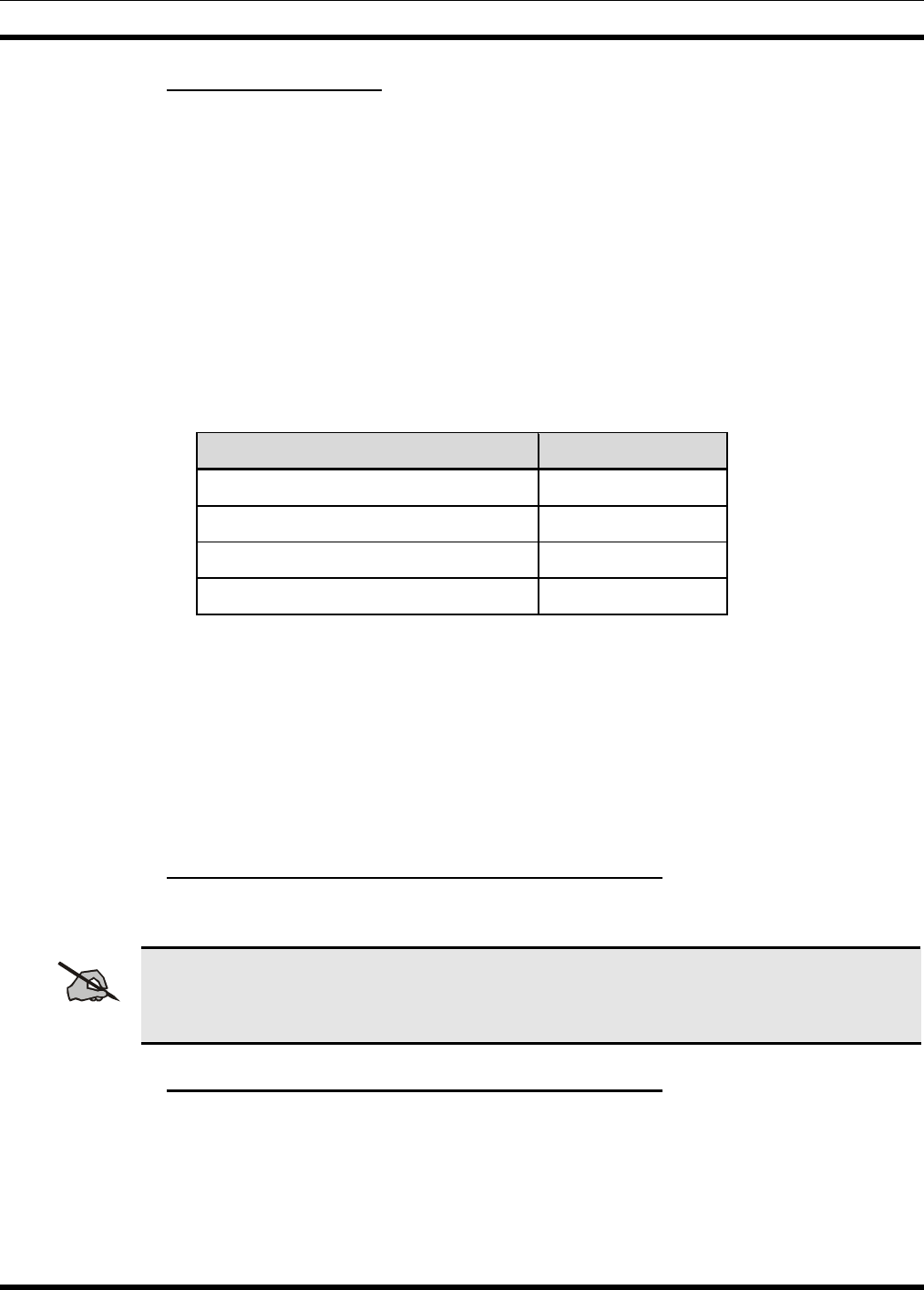
MM102554V1 REV B
69
8.5.10 Line Output (LO) Pot
The Line Out (LO) pot adjusts the line out level for an output signal level of 0 dBm.
If this is not a remotely controlled station, set the LO pot to zero (0).
To perform receiver tests on a remote station, the LO level may be set to 0 dBm into a 600 ohm load.
After these tests are completed, return the LO pot to zero.
For a remotely controlled station, perform the following steps to set the LO pot:
1. Set the Communication Test set for an “on-frequency” RF signal modulated by a 1 kHz tone at 60%
of rated system deviation (see Table 8-11).
2. Connect the Test Set RF OUT to the Receiver Front End Module RF IN connector (J2).
Table 8-11: Line Out Deviation Setting
SYSTEM TYPE 60% DEVIATION
Standard (25 kHz IF) 3.00 kHz
NPSPAC 2.40 kHz
Narrow (12.5 kHz narrowband) 1.50 kHz
P25 1.50 kHz
3. Measure the line output level at J101-3 and J101-4 across a 600-ohm load. Adjust the LO pot for a 0
dBm (775 mVrms) indication.
4. Remove the input signal from the receiver.
5. Repeat this procedure for each channel.
6. If this is a channel guard station, re-enable Channel Guard Decode.
Note: 1) the line input is terminated to prevent line audio deviation while adjusting channel guard
deviation.
8.5.11 P25 C4FM Deviation (DSP Module Adjustments)
This section provides instructions for aligning the DSP Module.
NOTE
Before aligning the DSP Module, the base station must be setup and aligned for conventional
analog operation as described in sections 8.5.1 through 8.5.10.
8.5.12 Enable the P25 Operation in the System Module
Perform the following steps to enable the P25 Operation in the System Module.
1. Connect the programming PC to the Data Port on the front of the T/R Shelf.
2. Run the Master-III programming software. Configure the base station for the desired analog
operation.
3. Set the P25 parameter on the OPTIONS screen to YES.
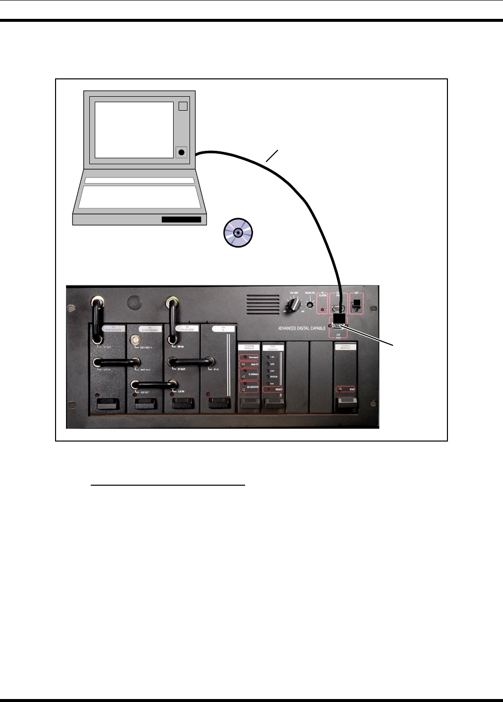
MM102554V1 REV B
70
4. Write the new personality to the base station.
5. Cycle base station power to ensure proper operation.
TQ3356 or
RS-232 Cable
DSP Port
Laptop computer
Software
DSP Programmer - TQS3413
Figure 8-4: MASTR III DSP Module Programmer Connections
8.5.13 Adjust P25 C4FM Deviation
1. Run the DSP Module Programmer software (TQS3413).
2. Connect the programming PC to the T/R Shelf DSP Port using the TQ3356 RS-232 cable.
3. Ensure the PC Serial Port is properly configured.
4. From the DSP Module Programmer menu or toolbar, choose Device⇒Personality⇒Read to get the
current personality saved in the DSP Module or File⇒Open to get a personality from the PC hard
drive.
5. Modify the DSP Module personality as described below. (Refer to Table and review the personality
parameters if needed).
• On the P25 Base station Settings menu, set the Transmit Test Mode for High Deviation Dotting
Pattern.
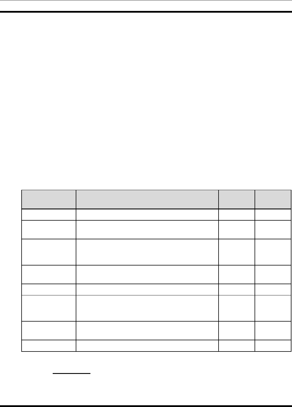
MM102554V1 REV B
71
• Select Device⇒Personality⇒Write from the Programmer menu or toolbar to upload the revised
personality.
NOTE: Recycling power to the base station is not required.
6. Observe that the base station is transmitting.
7. Measure the transmitter deviation of the P25 High Pattern. The deviation should be 2826 ±25 Hz. If
the deviation is within limits proceed to step 11.
8. If the deviation out of limits, adjust the High Deviation personality parameter. Entering a higher
value increases the deviation.
9. Select Device⇒Personality⇒Write from the Programmer menu or toolbar and upload the revised
personality.
NOTE: Recycling power to the base station is not required.
10. Repeat steps 6 thru 9 until the deviation is 2826 ±25 Hz.
11. Disable the Transmit Test Mode (Normal Operation) as described below.
• On the P25 Base station Setting menu, set the Transmit Test Mode for Disabled.
• Select Device⇒Personality⇒Write from the Programmer menu or toolbar to upload the
personality.
NOTE: Recycling power to the base station is not required.
Table 8-12: P25 Personality Parameters
PERSONALITY
PARAMETER DESCRIPTION RANGE DEFAULT
VALUE
Source ID Transmit Source ID for Landline Analog Interface. 1- 1
Talk Group ID Transmit Talk Group ID for Landline Analog
Interface. 1-65535 65535
TX Network
Access Code
(NAC)
Transmit Network Access Code for P25 Repeater and
Landline Analog Interface. Review TIA 102.BAAD
for detail NAC operation.
1-4095 659
(293 hex)
RX Network
Access Code Receive Network Access Code for P25 Repeater
operation. 1-4095 3967
(F7F hex)
Preempt Enable Enables a landline analog preempt over a RF Rx P25. On/Off On
Repeater Enable Enables P25 RF Rx to P25 RF TX operation. When
disabled, P25 RF Rx is only routed to the landline
analog interface.
On/Off On
Transmit Test
Mode Enables or disables various transmit test modes. N/A Disabled
High Deviation P25 High Pattern deviation setting. 0-32767 15000
8.5.14 SINAD Test
There are different SINAD values depending on the frequency band of the equipment (see step 3).
1. Connect the Communication Test Set output to the RF IN (J2) on the Receiver Front End module.
MM102554V1 REV B
72
2. Connect the Communication Test Set Audio Input to the Line Output. The line output in
differential; some test sets may require conversion to a single ended signal. If the conversion
hardware is not available, measure just one side of the line out, but do not use the other line out as
ground; connect test set ground to the MIII ground. Open the squelch.
3. Set the Communication Test Set to measure SINAD and adjust the RF level until an average 12 dB
SINAD is attained. For 800MHz systems, the level must be less than -119dBm (i.e. more negative
for example -120 dBm). For UHF and VHF systems, the level must be less than -116dBm (i.e. more
negative for example -117 dBm).
4. If the SINAD is worse than (i.e. greater than) the required level, service the receiver. Record the 12
dB SINAD value on the Repeater data sheet in section 12.6.
8.5.15 Squelch Adjustment
1. Connect the Communication Test Set as for the previous test.
2. Adjust the Communication Test Set RF level for an average 3 dB below the previous SINAD reading.
3. Adjust the Squelch until it just closes.
4. Record the Squelch setting on the data sheet. Remove the Communication Test Set from the station.
8.5.16 Transmitter Forward and Reverse Power
This test measures the Forward and Reverse power of each channel. After the station forward and reverse
power are verified, the station forward power will be adjusted to provide the required Effective Radiated
Power at the transmit antenna.
EFFECTIVE RADIATED POWER
Effective Radiated Power (ERP) is the result of the calculation of Station Forward Power, Combiner loss,
Feeder loss and Antenna gain.
CABLE LOSS (dB/100 meter)
FREQUENCY SUPERFLEX HELIAX
1/2” 7/8” 1 5/8”
150 MHz 2.77 1.50 0.919
450 4.96 2.74 1.69
824 6.90 3.85 2.40
960 7.51 4.20 2.62
8.5.16.1 TX Forward Power (TX)
1. Connect the 20 dB Directional Coupler to the station PA output at the back of the Repeater cabinet
2. Attach a 20 dB directional coupler and 150-watt RF load to the Transmitter RF Output.
3. Connect the RF Power meter to the attenuator port on the coupler.
4. Connect the MASTR-III Utility Programmer to the station and select PA Power.
5. Key the station, measure the Transmitter Output Power and adjust PA Power, if necessary, for the
forward power level required to achieve maximum power for the station. Record the output power.
6. Add directional coupler loss plus cable and connector loss to the RF Power meter measurement.

MM102554V1 REV B
73
POWER MEASUREMENT ACCURACY
If the measured value is within ±5% of maximum power, do not adjust.
7. Toggle the TX DISABLE switch and disable transmission (TX Disable LED on).
8.5.16.2 TX Reverse Power
1. Connect the RF Power meter to the reverse power port on the 20 dB coupler. Terminate the forward
directional coupler port.
2. Key the station, read the reflected power and record this value on the RF System data sheet. If this
value is greater than 4 watts, service is required to reduce the reflected power.
3. Toggle TX DISABLE to disable transmission.
4. Remove directional coupler and reconnect cable to antenna.

MM102554V1 REV B
74
9. SYSTEM FUNCTIONAL TESTS
9.1 GENERAL
The chapter describes the methods for functionally testing the MASTR III Conventional Base Station.
Upon completion of these tests, the base station is considered operational.
9.2 SETUP
The following system functional tests may require up to four (4) portable or mobile radios of the type to
be used on this system (conventional analog or P25 digital) - ideally they should be specimens from the
customer’s order. Many of the tests will only require two of these to be used.
Program all test radios with a minimum generic personality. The personalities should closely reflect the
personalities of the customer’s radios where possible.
9.3 CONVENTIONAL RADIO TEST
This test verifies the operation of a conventional analog base station.
1. Set the radios to the desired system or channel.
2. Ensure the channel is not busy and make a series of radio calls.
3. Confirm that the transmission can be heard in the receiving radio.
4. Set the radios for coded transmission (if programmed) and make a series of coded calls.
5. Ensure the receiving radio decodes the call.
9.4 P25 RADIO TEST
This test verifies the operation of a P25 base station.
9.4.1 P25 Individual Calls
1. Ensure the radios and base station are configured for P25 operation.
2. Select the desired P25 system.
3. Select the radio unit to call (callee source ID) from the pre-programmed individual call list or enter
the ID number on the radio keypad.
4. Make the call.
5. Confirm that the called radio unmutes according to the squelch mode defined in the radio personality
(monitor, normal, selective).
9.4.2 P25 Group Calls
1. Ensure the radios and base station are configured for P25 operation.
2. On the transmitting radio, select P25 system and the desired Talk Group/Conventional Channel.

MM102554V1 REV B
75
3. On the receiving radios, select the desired P25 system and Talk Group/Channel or turn scan on and
make sure the desired channel is in the scan list.
4. Make the call.
5. Confirm that the called radios unmute and receive the P25 call. The radio will unmute according to
the squelch mode defined in the radios’ personality (monitor, normal, selective).
9.5 REMOTE STATION OPERATION
This test verifies the remote control of the base station.
1. In multi-frequency stations, check remote frequency control.
2. In channel guard stations, the MONITOR switch on the console should disable channel guard decode.
Momentarily keying the transmitter will re-enable CG decode.
3. For Tone systems with CG ENABLE/DISABLE:
• When the console is switched to CG DISABLE, CG Decode should be disabled. Keying the
transmitter will not enable CG Decode.
• Switching to CG ENABLE will enable CG Decode unless the MONITOR switch has been
depressed. The microphone monitor switch will disable CG Decode even if the CG
DISABLE/ENABLE switch is in the enable position.
4. Place a series of individual and group calls to radios. Ensure radios receive calls.
5. Make a series of calls using conventional and P25 (if applicable) radios and verify Remote Controller
can monitor and respond to calls.
MM102554V1 REV B
76
10. MODULE TESTING AND ALIGNMENT
10.1 GENERAL
The chapter describes the methods available for testing and aligning individual modules. If modules are
suspected of being faulty, they should be tested and realigned by using one of the methods described in
Table 10-1.
Table 10-1: Module Test and alignment methods
TEST OR ALIGNMENT METHOD AFFECTED MODULES
Bench Testing
(Removing the modules from the Station and
using the TQ0650 RF Test Fixture)
All RF modules
In-Station Testing
(Using the extender cards) All modules
WARNING
Before removing or replacing any module, power to the station must be switched off.
The preferred method for testing and aligning individual modules is to perform the Bench Test and
Alignment. This involves removing the module from the base station and using the TQ0650 RF Module
Test Fixture to test and align the module as described in section 10.2. After the module realignment is
complete and it is reinstalled into the base station, it will be necessary to perform a full station alignment
according to the procedures in chapter 8.
Individual modules may also be tested in the base station by using an extender card. Refer to section 10.2
for instructions on using an extender card to test individual modules.
There are two types of extender cards available for use with the MASTR III Base Station T/R Shelf. One
extender card extends the modules installed in the RF section and the other for modules in the control
section. Table 10-2 indicates which modules can be extended by each extender card.
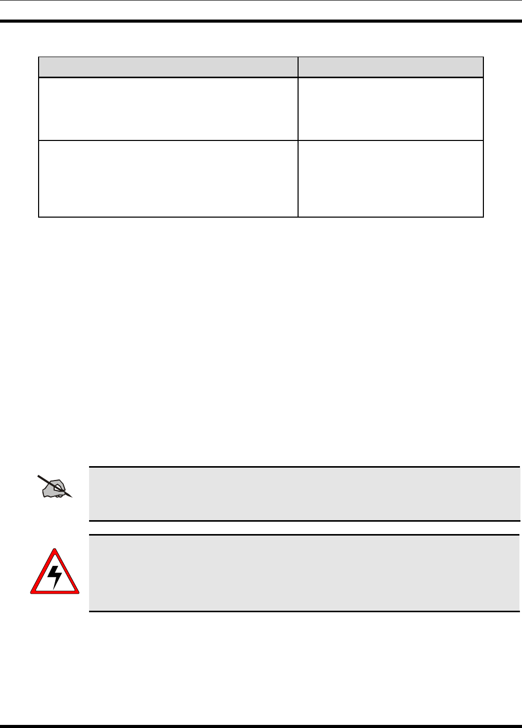
MM102554V1 REV B
77
Table 10-2: Extender Cards
EXTENDER CARD TYPE AFFECTED MODULES
188D5338G2 RF Section Extender Card • Transmit Synthesizer
• Receive Synthesizer
• RX Front End RF Module
• IF Module
188D5338G1 Control Section Extender Card • Power Module
• System Module
• DSP Module
• AMPF Module
• Data Module
10.2 BENCH TESTING
Bench Testing must be performed in a relatively clean shop environment using the TQ0650 RF Module
Test Fixture. Usually when a module is suspected of being defective or out of alignment, the affected
channel is to be taken out of service and the failed module is to be removed and replaced with a known
good module. If a replacement module is installed, the station should be completely realigned and the
channel returned to service. The module removed is then taken to a Maintenance Facility for bench
testing and alignment.
The TQ0650 RF Module Test Fixtures 344A4235P1 (no longer available) and the TS101285V1 are
capable of testing the modules listed in Table 10-3. Instructions for using the RF Module Test Fixture are
contained in manuals LBI-38805 (344A4235P1) and MM101885V1 (TS101285V1), which are included
in the TQ0650 package. These manuals provide instructions for setting up the test fixture and running the
test software. A personal computer is also required.
The test technician should refer to the applicable technical manual for the module under test for detailed
alignment requirements.
NOTE
There are no bench tests for the System Module. Should this module fail during in-station
alignment, it is to be replaced and the failed module returned for repair.
WARNING
Before removing or replacing a module, power to the station must be switched off.
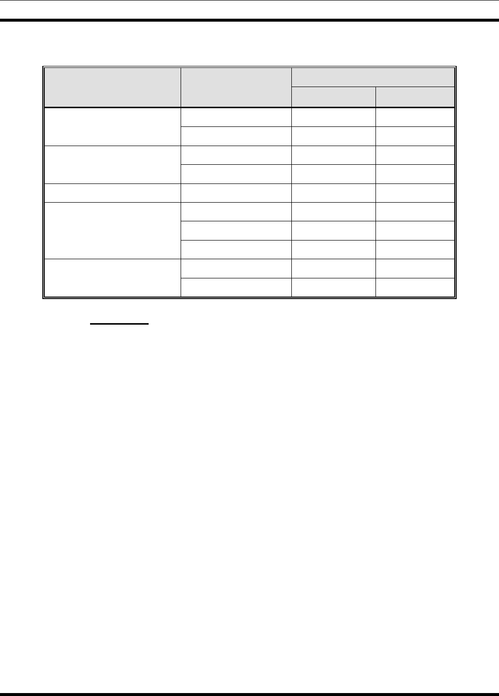
MM102554V1 REV B
78
Table 10-3: TQ0650 and MASTR III RF Module Compatibility Chart
RF MODULE TEST FIXTURE MODULE PART NUMBER
TS101285V11 344A4253P1
19D902780 X X
Transmit Synthesizer EA101685 X
19D902781 X X
Receive Synthesizer EA101684 X
RX Front End RF Module 19D902782 X X
19D902783 X X
EA101401 X
IF Module
EA101794 X
19D902797 X X
Power Amplifier EA101292 X
10.2.1 Procedure
To remove a module for bench testing, the following steps are to be taken:
1. Switch OFF power to the affected channel (T/R Shelf).
2. Remove the module.
3. If possible, replace the module with a known good module and realign the Base Station and return it
to service.
4. Return the defective module to the test facility and connect it to the RF Module Test Fixture.
5. Bench Test the module according to the instructions in LBI-38805 or MM101885V1. Test and
realign the module if possible. If it fails the testing, it should be sent for warranty repair or
replacement.
When testing is complete, replace the module and re-check alignment as follows:
1. Power to the channel must be switched off.
2. Place the module into the correct slot in the station.
3. Reapply power to the channel.
4. Perform complete station alignment.
5. Return the channel into service.
MM102554V1 REV B
79
10.3 IN-STATION TESTING
For In-Station Testing, refer to the appropriate technical manual for the module under test.
WARNING
Before removing or replacing a module, power to the station must be switched off.
10.3.1 Procedure
To prepare the module for In-Station Testing, the following steps are to be taken:
1. Remove power to the affected channel (T/R Shelf).
2. Remove the module and place the RF Module Extender Card into the T/R Shelf.
3. Insert the module into the Extender Card.
4. Reapply power to the channel (T/R Shelf).
5. Tests may now be performed. Refer to the applicable module maintenance manual for testing
information.
When testing is complete, replace the module and re-check alignment as follows:
1. Power to the channel must be switched off.
2. The Extender Card is to be removed and the module replaced into the correct slot in the station.
3. Power is to be reapplied to the channel.
4. Alignment must be verified and station realigned if necessary.
5. Return the channel into service.
10.4 CHANGING THE BASE STATION FREQUENCY
NOTE
The following procedures may be used in the field to retune a station if an RF module
has been repaired or replaced or the station frequency has been changed. The
preferred method is to use the RF Test fixture and the module alignment found in
section 10.2 and the specific RF module maintenance manual.
Changing the frequency in a MASTR III ADC Base Station requires frequency planning, examination of
the antenna system specifications, realignment of the RF system, and realignment of the Base Station.
The preferred method for retuning modules is to remove the modules from the Station as described in
section 10.2 and to use the RF Test Fixture to realign the RF modules.
The only modules that require realignment are the TX and RX Synthesizer and RX Front End modules,
but the remaining modules should be checked to ensure that they still operate correctly. When the
module realignment is complete, reinstall the modules and perform a complete station alignment using the
procedures in the Station Alignment section 8.4.
MM102554V1 REV B
80
If it is necessary to retune the modules in the field and an RF Test Fixture is not available, then use the
following procedures to realign the modules. The TX and RX Synthesizers can be retuned in the field by
using the metering functions available with the Utility handset SPK9024, MASTRUTL (TQ0619), or
MSEDIT (TQ0653). The VCO tune voltage from the RX Synthesizer slot in the T/R shelf is connected to
the external metering jack (EXT_JCK) in the System Module.
10.4.1 Vendor Equipment
The specifications of the following equipment, if used, must be checked for Frequency Isolation and
Frequency Separation issues and should be realigned where necessary:
• Combiner
• Multicoupler
• Filter
• Antenna element
10.4.2 800 MHz Stations
NOTE
There is no requirement to tune 800 MHz Station Front End or IF Modules.
WARNING
Before removing or replacing a module, power to the station must be switched off.
1. Remove the cover of the RX Synthesizer and place on an extender card.
2. Program the station for the desired TX and RX frequencies.
3. Adjust the RX Synthesizer trimmer until the LED on the front of the module goes out.
4. Monitor the EXT metering field and adjust the trimmer for a V Test reading of 5 VDC on the EXT
Metering field or on J3 pin 23A.
5. Remove RX and TX Synthesizers. Place the RX Synthesizer in slot farthest to the left and the TX
Synthesizer on the extender in the slot next to the RX Synthesizer. Using a U-Link (344A3052P1),
connect the TX Synthesizer Ref In (J1) to the RX Synthesizer Ref Out (J3).
6. Key the station with the REM PTT switch on the System Module.
7. Adjust the trimmer on the TX Synthesizer for a reading of 5 VDC on the EXT Metering field or on J3
pin 23A.
8. Replace all modules into the Station and confirm complete station alignment as described in Station
Alignment section.
MM102554V1 REV B
81
10.4.3 UHF Stations
NOTE
There is no requirement to align UHF Station TX Synthesizer or IF Modules.
WARNING
Before removing or replacing a module, power to the station must be switched off.
1. Remove the cover of the RX Synthesizer and place on an extender card.
2. Program the station for the desired TX and RX frequencies.
3. Adjust the RX Synthesizer trimmer until the LED on the front of the module goes out
4. Monitor J2 and align FL1 for a peak output level using a Spectrum Analyzer or RF Voltmeter.
Programmable bandwidth is ±1MHz.
5. Place the Front End Module on an extender card and connect the LO out of the RX Synthesizer and
the IF out of the Front End to the IF Module with 50Ω Coax cable.
6. Preset the Front End tuning slugs according to the instructions in the RX Front End technical manual
and apply an “on frequency” signal into the RF In on the Front End Module.
7. Monitor the RSSI metering function and adjust the level of the “on frequency” signal to the
responsive range of the meter.
8. Tune the Front End tuning slugs for a peak on the RSSI meter while reducing the input signal level to
keep the meter in the responsive reading range.
9. Replace all modules into the Station and confirm complete station alignment as described in Station
Alignment section.
10.4.4 VHF Stations
NOTE
There is no requirement to tune the 19D902780G1 VHF TX Synthesizer Module.
WARNING
Before removing or replacing a module, power to the station must be switched off.
1. Ensure that the TX Synthesizer Dip switches are set for the required frequency range.
2. Align the RX Synthesizer trimmers until the LED on the front panel of the module goes out.

MM102554V1 REV B
82
3. Monitor J2 and align FL1 for a peak output level using a Spectrum Analyzer or RF Voltmeter.
Programmable bandwidth is ±1MHz.
4. Place the Front End Module on an extender card and connect the LO out of the RX Synthesizer and
the IF out of the Front End to the IF Module with 50Ω Coax cable.
5. Preset the Front End tuning slugs according to the instructions in the RX Front End technical manual
and apply an “on frequency” signal into the RF In on the Front End Module.
6. Monitor the RSSI metering function and adjust the level of the “on frequency” signal to the
responsive range of the meter.
7. Tune the Front End tuning slugs for a peak on the RSSI meter while reducing the input signal level to
keep the meter in the responsive reading range.
8. Replace all modules into the Station and confirm complete station alignment as described in Station
Alignment section.
10.5 STATION ADJUSTMENTS FOR REMOTE CONTROL OPERATION
Although audio levels should be considered on a system basis, it is appropriate to set the levels of the
remote controller and the control station panel by themselves with reference to the levels required by the
transmission path and then connect the controller(s) and station to the path. The transmission path, if it is
more than just a simple twisted pair, is usually set up with a "test tone". The "average voice" level is
defined as being a certain number of decibels below the test tone. The test tone is normally the maximum
level that can be sent through the path without clipping or being regulated. Although there is no definite
agreement on the difference between the test tone and average voice levels, 10 dB is an appropriate level.
In order to align the Remote Controller and T/R Shelf properly, it will be necessary to have some
information on the transmission path. This will help to determine the levels at each end required by the
system. Specifications needed include:
1. Loss at 1 kHz
2. Test tone or maximum level
3. Average voice level (if defined)
4. Loss at 2175 Hz (if tone remote)
The DSP Board performs tone detection in a tone remote installation. The "Secur-it" tone Decoder on
this board has a dynamic range of approximately 9 dB. The system must be set up such that the "Secur-it"
tones from all remotes in the system arrive at the T/R Shelf within this 9 dB window.
10.5.1 Line Out Level Adjustment
U36-1 is used to set the line out level. Analog switch U14 selects which audio source is routed to the line.
Possible sources are LOCAL MIC, VOL/SQ, auxiliary receiver audio, auxiliary receiver audio summed
with VOL/SQ (simultaneous monitor), DSP LINE/TX AUDIO, MODEM LINE data, OPEN (used for
battery alarm), GROUND (used for no transmission, and LINE IN audio (used for four wire loop around).
A battery alarm tone and/or VG ALERT tone may also be summed in with whichever source is selected
with the exception of GROUND. Typically LOCAL MIC, VOL/SQ, DSP LINE/TX AUDIO, OPEN, or
GROUND will be selected.
The gains in the circuitry are set such that 100 mVrms in on MIC HI or 1 Vrms (3 kHz deviation) in on
VOL/SQ HI (REPEAT AUDIO) will produce the same line output level. The gains for VG ALERT tone
MM102554V1 REV B
83
and battery alarm are also designed to provide the proper levels without adjustments. The LINE output
level should be adjusted with a 100 mVrms, 1 kHz signal in on MIC HI or a 1 Vrms, 1 kHz signal in on
VOL/SQ HI.
10.5.2 DSP Line In Level Adjustment
Typically, the TX AUDIO and LINE OUT levels should be adjusted prior to adjusting the DSP LINE IN
level. DSP TX AUDIO and DSP LINE/TX AUDIO are typically line audio or VOL/SQ HI audio that has
been processed by the DSP Board.
A DSP Board is always present; this DSP processed line in audio will normally be selected by analog
switches U14 (DSP LINE/TX AUDIO to line out) and U15 (DSP TX AUDIO to transmit audio) on the
System Module when line in audio is selected. The level for DSP TX AUDIO and DSP LINE/TX AUDIO
must be adjusted on the DSP Board.
10.5.3 DSP Level Adjustments
The DSP LINE IN level into the DSP must be adjusted using U15-0 (DSP line cancellation level) and
U15-1 (DSP line input level) located on the DSP Board. If two-wire audio is used then both electronic
pots must be adjusted. If four-wire audio is used then only U15-1 needs to be adjusted.
For two wire installations the DSP line cancellation level pot (U15-0) is used to remove what the T/R
Shelf is sending to the line. While the T/R Shelf is sending received audio down the line, the line
cancellation pot should be adjusted to minimize the signal level at TP1 on the DSP Board. This leaves
only what is received from the remote. This signal is then level adjusted using the DSP line input level
adjust pot (U15-1) and input into the DSP.
NOTE
System Modules 19D902590G6 & G7 have TP1 extended to the board edge connector and
may be metered on the MASTR III backplane at J5, Pin 28A.
If four-wire audio is used, the DSP line cancellation pot must be set to zero.
The DSP also performs a compressor function on its DSP line input. The threshold for this compressor
must be adjusted as well. The line level should be adjusted on the DSP Board prior to setting the
compressor threshold.
MM102554V1 REV B
84
11. PREVENTATIVE MAINTENANCE
11.1 GENERAL
Preventative Maintenance is a periodic check of the station’s operation. The results of the check may
indicate that the station needs realignment if its performance has drifted from the installation values or the
values documented in the previous inspection.
It allows for:
1. Operational test and re-adjustment of each Base Station’s alignment,
2. Operational test and re-adjustment of RF System equipment,
3. Operational test and re-adjustment of the Power System.
Preventative Maintenance should be performed every 6 months, or sooner if required by the customer.
The tests will follow those defined in this manual and will require the test engineer to refer to the
Installation Checklists or last Preventative Maintenance Checklists to determine any variance in
performance.
The results of these tests are to be recorded on the Preventative Maintenance Checklists in section 12.7
11.2 BASE STATIONS
WARNING
To disconnect the power to the base station for maintenance, unplug the power supply
from the AC outlet.
11.2.1 Test Equipment
The Test Equipment requirement is as defined in the “Station Test and Alignment” Section. Ideally, the
same test equipment should be used for every channel at the site. If more than one of a particular type of
Test Equipment is used, ensure that they are calibrated to each other.
NOTE
For checking station frequency, a high accuracy reference is required (better than 1 part in
10-7). The internal oscillator on many counters is not sufficiently precise.
11.2.2 Tests
Refer to the “Station Test and Alignment” Section for detail of the tests. Perform tests to ascertain
current levels and note these on the Checklist. If adjustment is necessary, perform the realignment and
note the new levels and Control Pot settings for each test.

MM102554V1 REV B
85
11.3 RF SYSTEM
This test does not address RF System between the bulkhead and the antenna elements. The RF System
comprises:
1. Combiner
2. Multicoupler
3. Receive Filter
4. RF Cabling to Bulkhead
11.3.1 Combiner
Follow the test procedures defined in the Combiner vendor manual to ensure correct performance for each
and for all channels. If alignment is required, follow the procedures outlined in the vendor’s manual.
Document and file the results with the Base Station Checklists.
11.3.2 Multicoupler
Follow the test procedures defined in the Multicoupler vendor manual to ensure correct performance for
each and for all channels. If alignment is required, follow the procedures outlined in the vendor’s
manual. Document and file the results with the Base Station Checklists.
11.3.3 Receive Filter
Follow the test procedures defined in the Receive Filter vendor manual to ensure correct performance for
each and for all channels. If alignment is required, follow the procedures outlined in the vendor’s
manual. Document and file the results with the Base Station Checklists.
11.3.4 RF Cabling to Bulkhead
RF Cabling includes coaxial cables, power sensors and RF protection. If tests indicate that the RF
Cabling is in error, follow the test procedures in this manual for power sensors and RF protection to
ensure correct performance. If alignment is required, follow the procedures outlined this manual.
Document and file the results with the Base Station Checklists.
11.4 POWER SYSTEM
Follow the Power System test procedures defined in the Power System section of this manual to ensure
correct performance. If alignment is required, follow the procedures outlined in the vendor’s manual.
Document and file the results with the Base Station Checklists.

MM102554V1 REV B
86
12. CHECKLISTS
These checklists, when filled in, will provide a complete record of the MASTR III Conventional or P25
Base Station installation.

MM102554V1 REV B
87
12.1 SITE DATA SHEET
Customer Name: _________________________________________________________
Local Customer Contact Name: _________________________________________________________
Local Customer Phone: _________________________________________________________
Site Name: _________________________________________________________
Site Address: _________________________________________________________
_________________________________________________________
_________________________________________________________
Site Telephone Number: _________________________________________________________
If Site is Leased, Owner's Name\Tel: _________________________________________________________
Access Controlled by (Name, Phone): _________________________________________________________
Site Latitude (Deg., Min., Sec.): _________________________________________________________
Site Longitude (Deg., Min., Sec.): _________________________________________________________
Site Elevation above sea level: _________________________________________________________
FCC License ID/Call Sign: _________________________________________________________
Site Equipment Type: Conventional Station P25 Station Encrypted Station
Number of Channels: _________________________________________________________
Check Control Options: DC Remote Operation Repeater Option
DC Remote /Repeater Tone/Remote Repeater
Multisite Audio Link Loss (dB) _________________________________________________________
Multisite Link type: Leased Line Microwave FiberOptic
Installation Date: _________________________________________________________
Installed By (Company Name): _________________________________________________________
Tower Type: Self Supporting
Guyed
Monopole
Other
Tower Height: _________________________________________________________
Tower FAA Options: Painted Lights
Antenna System: Single Multi
If Multi-Antennas, Number of Transmit: ______________ Transmit Antenna Height: _______________
If Multi-Antenna, Number of Receive: ______________ Receive Antenna Height: _______________
Transmit Helix Type: ______________ Transmit Antenna Azimuth: _______________
Receive Helix Type: ______________ Receive Antenna Azimuth: _______________
Transmit Antenna Model ______________ Transmitter Combiner Model: _______________
Receive Antenna Model: ______________ Tower Top Amplifier: YES NO
If Tower Top Amplifier, Model: _________________________________________________________
Receiver Multicoupler Model: _________________________________________________________

MM102554V1 REV B
88
12.2 INSTALLER PROFILE DATA SHEET
Installer’s Company Name: ______________________________________
Installer’s Telephone Number: ______________________________________
Installer’s Name (s): ______________________________________
______________________________________
Technician’s Name (s): ______________________________________
______________________________________
Date of Testing Complete: ______________________________________
Test Equipment Used,
if other than specified: ______________________________________
______________________________________
______________________________________
______________________________________
______________________________________
______________________________________
______________________________________

MM102554V1 REV B
89
12.3 ANTENNA SYSTEM INSTALLATION CHECKLIST
SITE ______________
ANTENNA ______________
INSPECTED BY ______________
DATE ______________
CHECKLIST:
1. What is make of antenna? ______________
2. What is type of antenna? ______________
3. What is design gain of antenna? ______________ dB
4. What is bearing of antenna? ______________
5. What is height of antenna above ground? ______________ Ft
6. Are hoisting grips installed as specified? ______________
7. Is cable secured to tower at specified intervals? ______________
8. Is cable grounded at top of tower? ______________
9. Is cable grounded at bottom of tower? ______________
10. Is cable grounded at point where it enters building? ______________
11. Is cable feed-through properly installed? ______________
12. Are coaxial connectors weather-sealed? ______________
13. Is cable entrance weather-sealed? ______________
14. Is there an AM mast within 2 miles of this site? ______________

MM102554V1 REV B
90
12.4 EQUIPMENT INSTALLATION CHECKLIST
SITE ______________
CABINET ______________
INSPECTED BY ______________
DATE ______________
CHECKLIST 1:
1. Verify that the cabinets are installed as located in the site plan drawing.
______________
2. Verify each cabinet/rack is correctly fastened to the floor in all four (4)
corners.
______________
3. For cabinets, verify the optional cable ducts have been correctly
installed. ______________
4. For racks, verify all racks are bolted to adjacent rack at the top and
bottom. ______________
5. For cabinets, verify the top plate is correctly installed on the RF
cabinet. ______________
6. Verify the RF equipment is correctly installed. ______________
7. Ensure all special installation requirements, provided by System
Engineering, have been completed correctly.
______________
8. Verify all metallic fixtures and room parts are connected to the internal
ground HALO.
______________
9. Verify the AC power is equipped with a Joselyn, or equivalent, AC
protector in addition to all other AC power protection.
______________
10. Verify all EDACS cabinets, cable trays, and/or cable duct systems are
connected to the internal ground HALO.
______________
11. Verify the GETC lightening circuitry is properly installed for each
GETC. ______________
12. Ensure all special installation requirements, provided by System
Engineering, have been completed properly.
______________

MM102554V1 REV B
91
12.5 POWER SYSTEM INSTALLATION CHECKLIST
AC SYSTEM YES/NO SITE ______________
GENERATOR YES/NO
______________
AC/DC SYSTEM YES/NO INSPECTED BY ______________
BATTERY SYSTEM YES/NO DATE ______________
UPS SYSTEM YES/NO
CHECKLIST:
AC SYSTEM
1. Site isolation and protection is installed and operating ______________
2. Input AC power, (voltage and current) is as specified ______________
3. Input AC power breaker is correctly rated for the site power load ______________
4. Input AC power cabling is sufficient for site loading ______________
5. Customer’s input AC power breaker operates correctly ______________
6. AC distribution, voltages and individual breaker operation to equipments ______________
GENERATOR SYSTEM
7. Generator, bypass switch and automatic switch-over operates correctly ______________
8. Generator output voltages are as specified ______________
AC / DC SYSTEM
9. Rectifier output to converters is as specified ______________
10. Rectifier output breaker operates correctly ______________
11. Converter output breakers operate correctly ______________
12. Converter output voltages are as specified ______________
13. Each associated equipment or cabinet is operating correctly ______________
BATTERY SYSTEM
14. Battery system connectivity is correct as per design document ______________
15. Battery system is electrically safe ______________
16. “Wet” cells prepared and adequate fume extraction provided ______________
17. Cabling is safely installed such that it is not a hazard ______________
18. Output voltage is as specified across all the cells ______________
19. Battery system will Charge ______________
20. Battery power applied to power distribution equipments ______________
21. Battery voltage applied to site equipment is as specified ______________
UPS SYSTEM
22. UPS system installed to specifications and successfully completes all Vendor
manual tests ______________
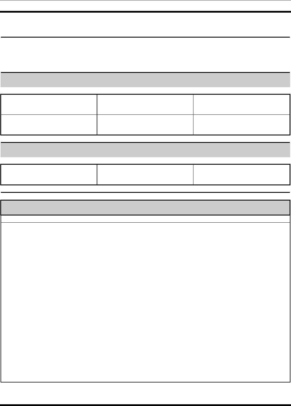
MM102554V1 REV B
92
12.6 REPEATER TEST DATA
CUSTOMER: ________________________________ SITE NAME: _________________________________
CHANNEL NUMBER: _______ TESTED BY: ________________________________ DATE: ____________
REPEATER GENERAL IDENTIFICATION:
MODEL NO.:
RX FCC ID #:
RX FREQUENCY (MHz):
SERIAL NO.:
TX FCC ID #
TX FREQUENCY (MHz):
P25 REPEATER IDENTIFICATION:
SOURCE ID #:
TALK GROUP ID #:
TX NETWORK ACCESS CODE:
STATION ALIGNMENT
ALIGNMENT/TEST POT UNITS LEVEL POT VALUE
LINE INPUT LI
CHANNEL GUARD CG Hz ____________ ____________
TRANSMIT LIMITING TX kHz ____________ ____________
REPEATER GAIN RG kHz ____________ ____________
DSP LINE INPUT DLI kHz ____________ ____________
COMPRESSOR GAIN CP kHz ____________ ____________
COMPRESSOR THRESHOLD CT kHz ____________ ____________
DSP CANCELLATION DC ____________ ____________
LINE OUTPUT LO dBm ____________ ____________
SENSITIVITY @ 12 dB SINAD SINAD dB ____________ ____________
SQUELCH SQUELCH dB ____________ ____________
TRANSMIT FORWARD POWER PA Watts ____________ ____________
TRANSMIT REVERSE POWER Watts ____________ ____________

MM102554V1 REV B
93
12.7 PREVENTATIVE MAINTENANCE REPEATER TEST DATA
REPEATER # __________
Alignment/Test Pot Required
Value Measure
d Value Adjusted
Value Pot
Value
Channel Guard WB CG 750 ± 25 Hz
NPSPAC 600 ± 25 Hz
NB 500 ± 25 Hz
P25 500 ± 25 Hz
Transmit Limiting WB TX 4.50± 0.1 kHz
NPSPAC 3.60 ± 0.1 kHz
NB 2.25± 0.1 kHz
P25 2.25± 0.1 kHz
Repeater Gain (CG Disabled) WB RG 3.00 ± 0.1 kHz
NPSPAC 2.40 ± 0.1 kHz
NB 1.50 ± 0.1 kHz
P25 1.50 ± 0.1 kHz
DSP Line Input Deviation WB DLI 2.80 ± 0.1 kHz
(CG Disabled) NPSPAC 2.25 ± 0.1 kHz
NB 1.40 ± 0.1 kHz
P25 1.40 ± 0.1 kHz
Compressor Gain (CG Disabled) WB CP 3.00 ± 0.1 kHz
NPSPAC 2.40 ± 0.1 kHz
NB 1.50 ± 0.1 kHz
P25 1.50 ± 0.1 kHz
Compressor Threshold WB CT 4.00 ± 0.1 kHz
NPSPAC 3.20 ± 0.1 kHz
NB 2.00 ± 0.1 kHz
P25 2.00 ± 0.1 kHz
Repeater Line Output Level LO +11 to -20
dBm
DSP Line Input Level LI +11 to -20
dBm
SINAD 12 dB
Squelch Squelch 10 dB
Transmit Forward Power PA 50-100%
Watts
Transmit Reverse Power <4 Watts
INSPECTED BY
________________________________________________________
DATE
________________________________________________________

M/A-COM Wireless Systems
221 Jefferson Ridge Parkway
Lynchburg, Virginia 24501
(Outside USA, 434-385-2400) Toll Free 800-528-7711
http://www.macom-wireless.com/ Printed in U.S.A.