HARRIS TR-0047-E P5300 900 MHz Portable Radio User Manual Manual
HARRIS CORPORATION P5300 900 MHz Portable Radio Manual
UserManual.wiki
>
HARRIS
>
TR 0047 E User Manual
Manual
Navigation menu
Upload a User Manual
Namespaces
Wiki Guide
HTML
PDF
Info
Views
User Manual
Discussion / Help
Navigation


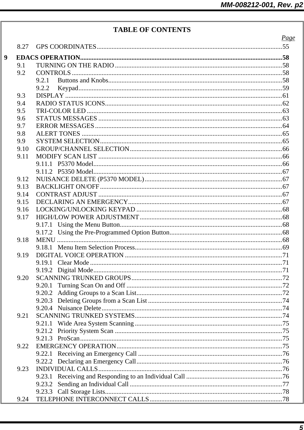
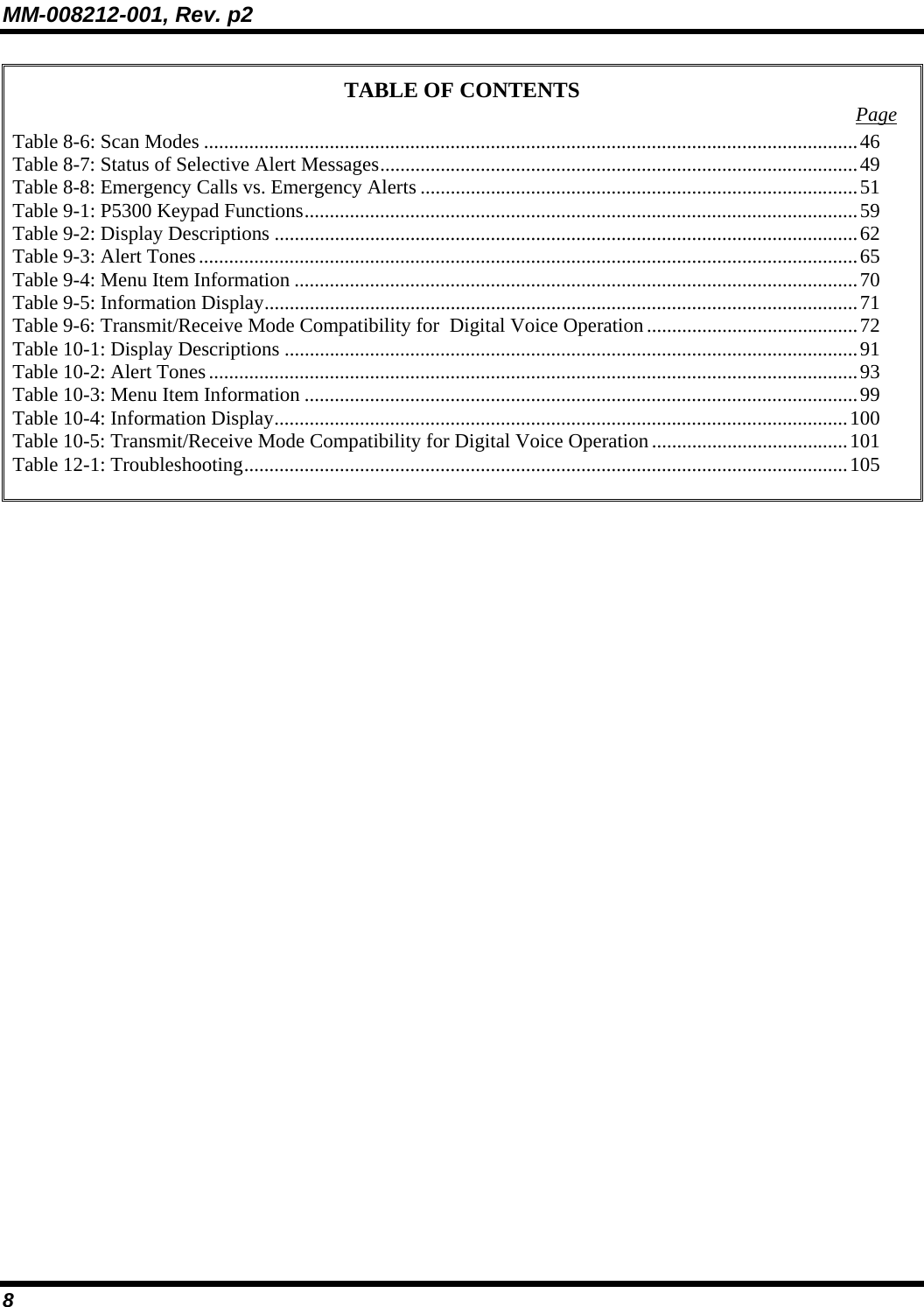


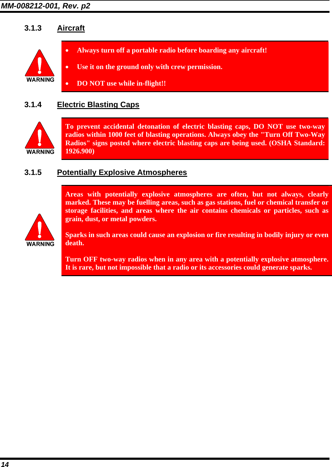


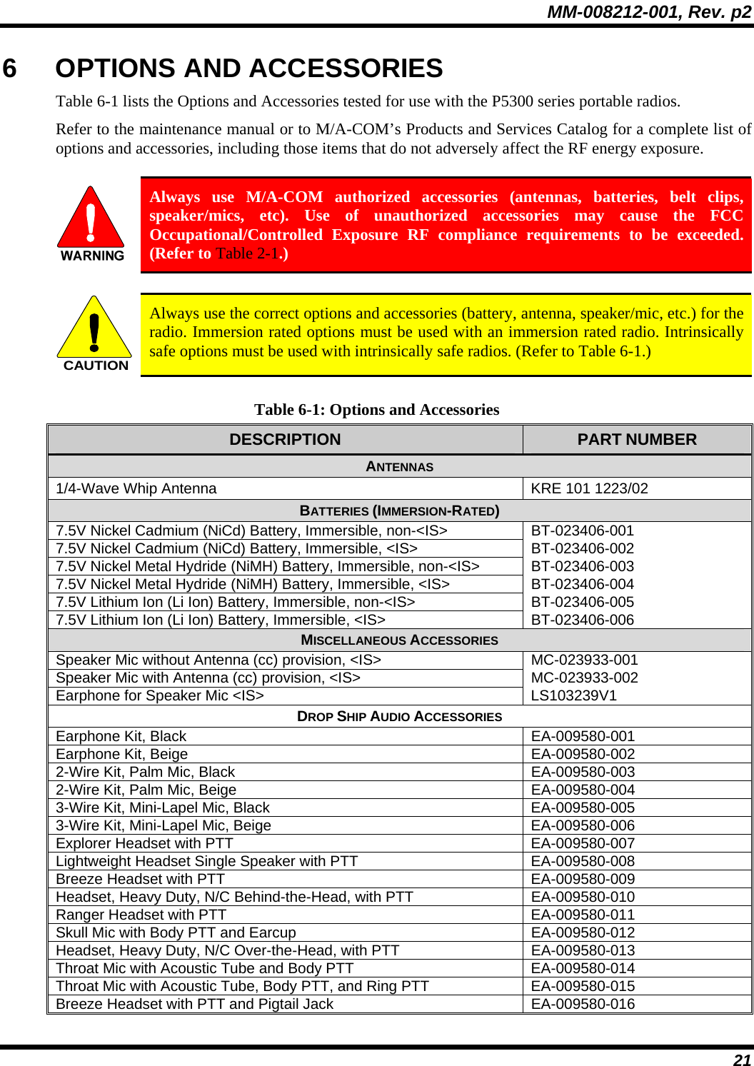
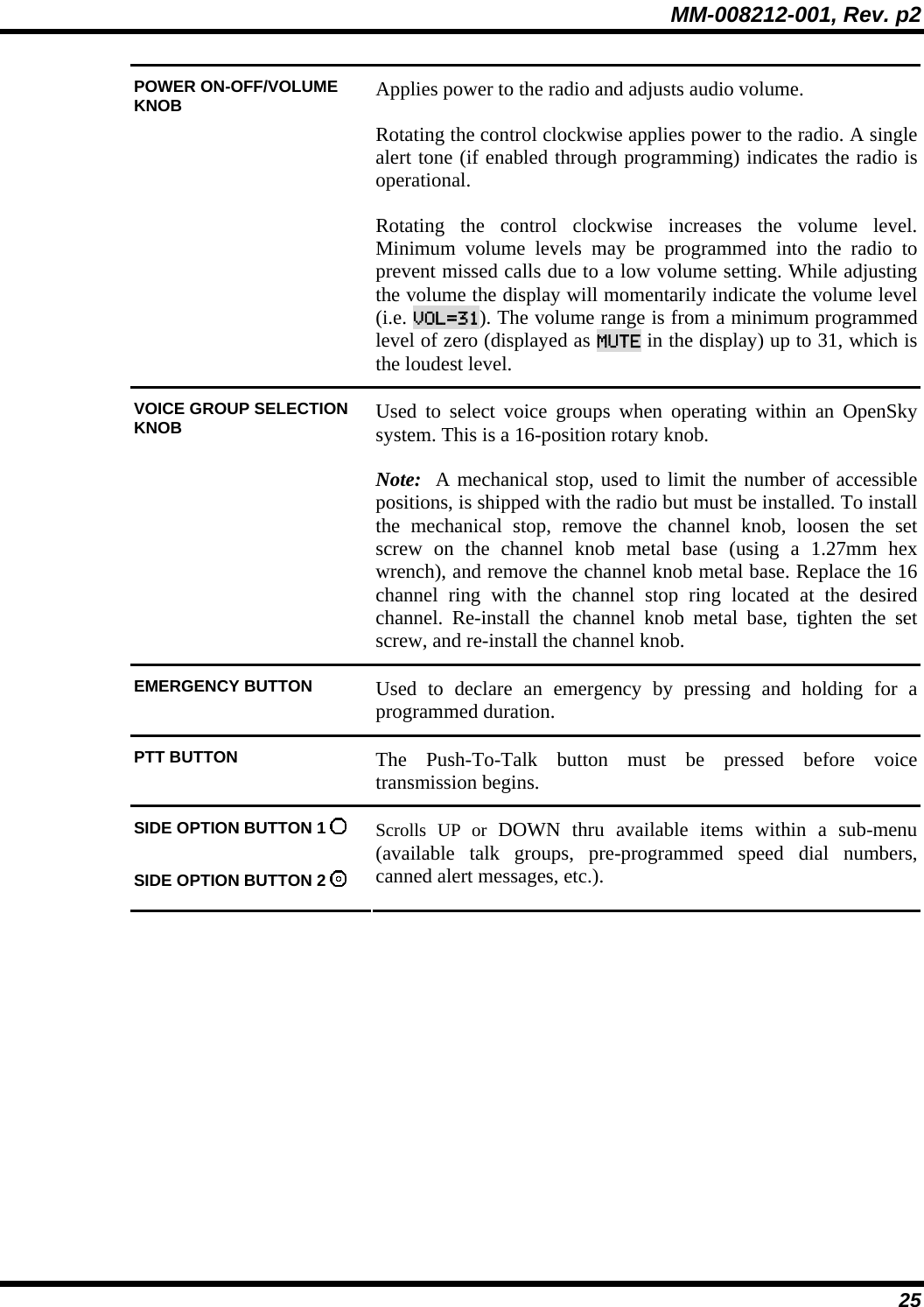


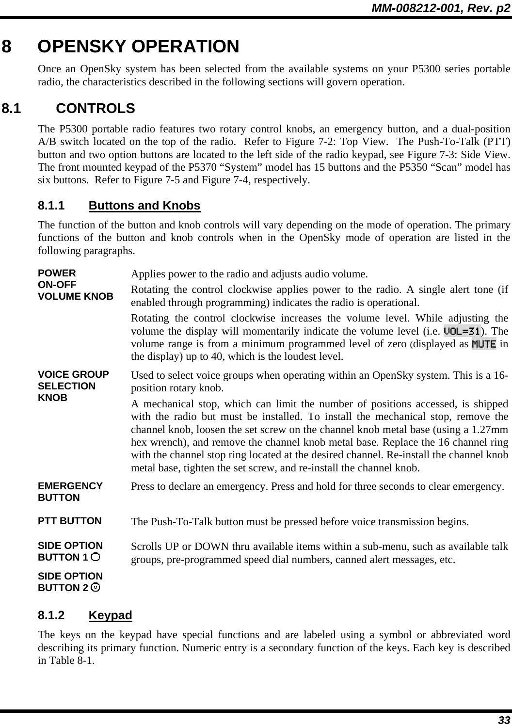
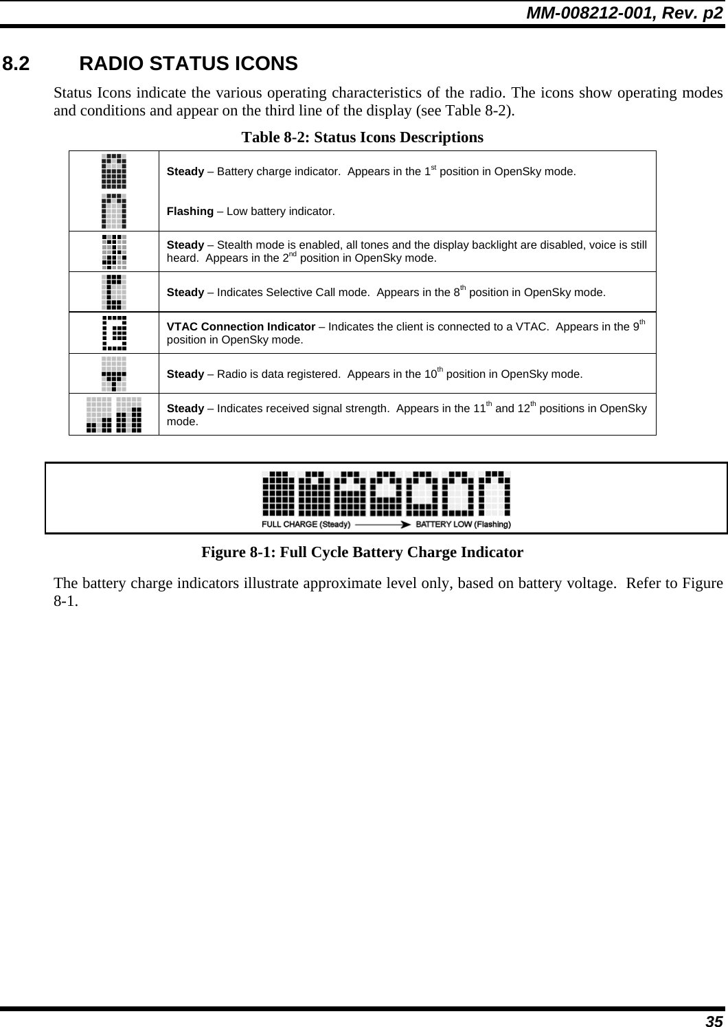
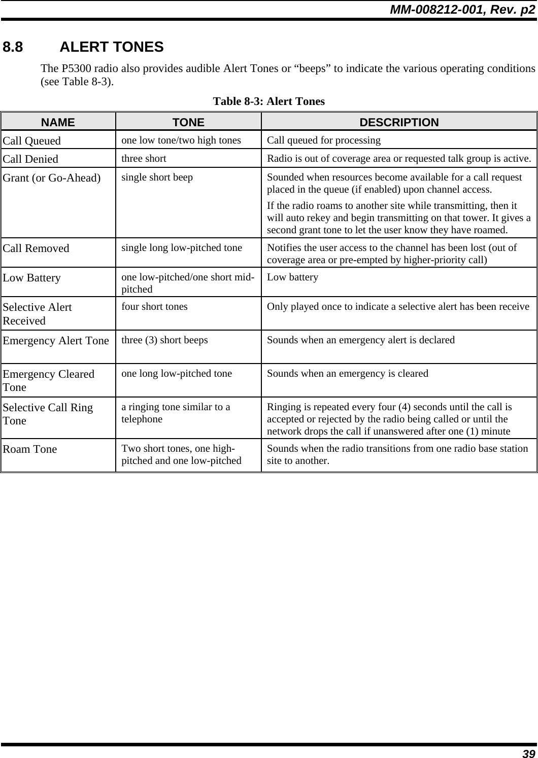
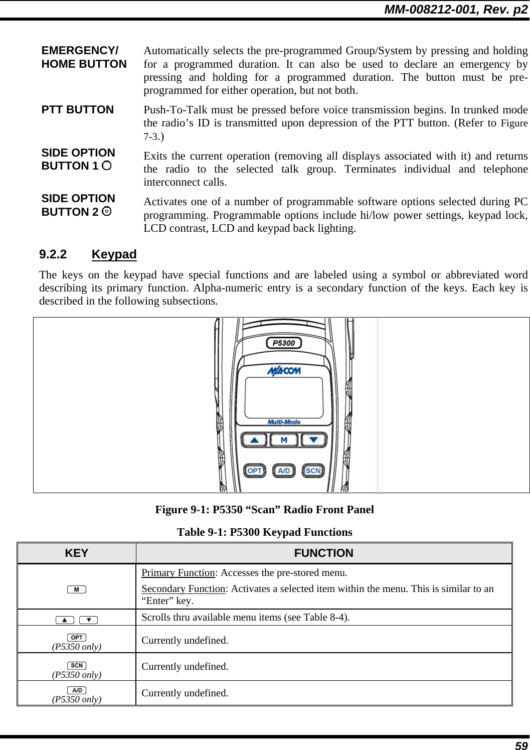
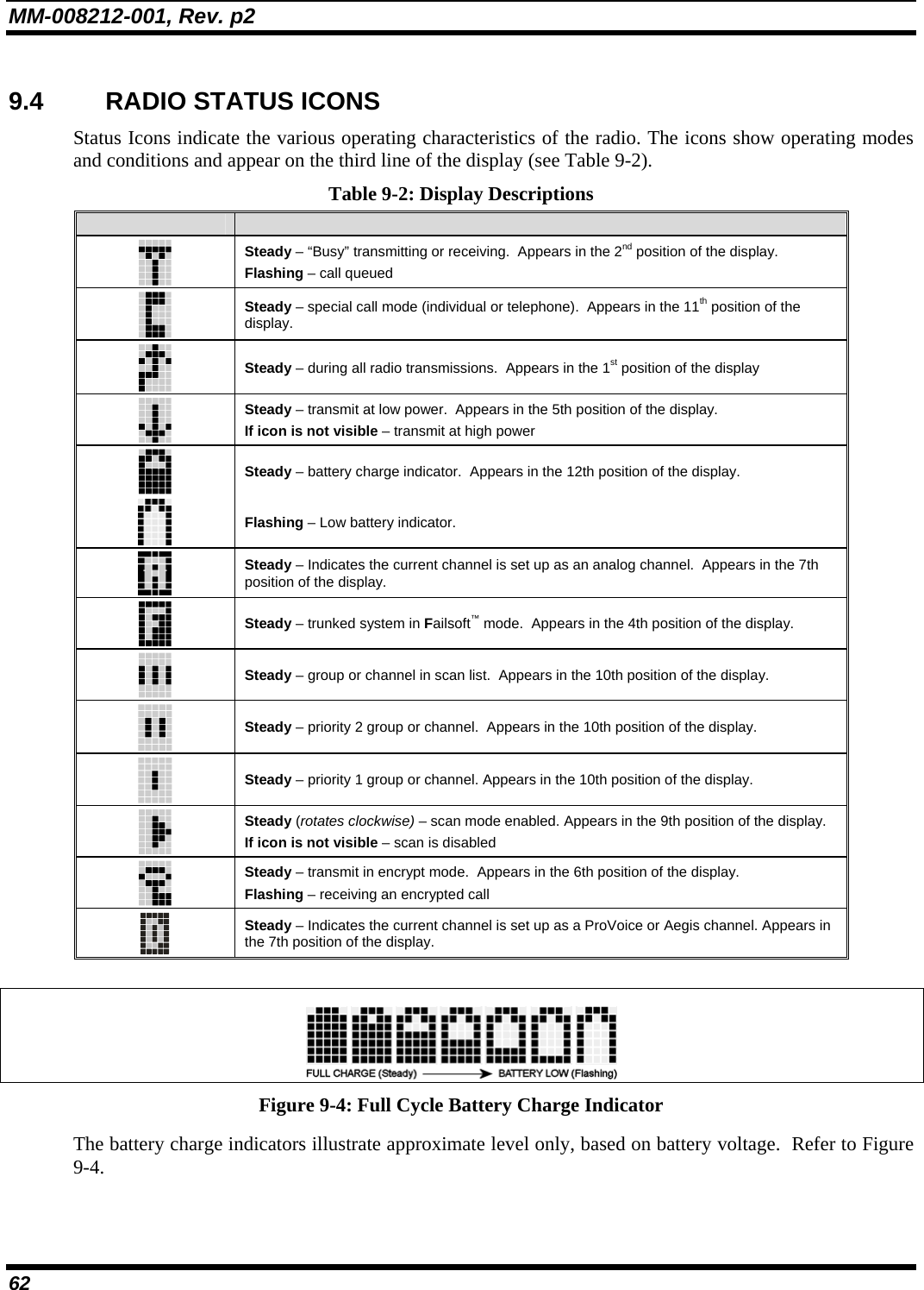
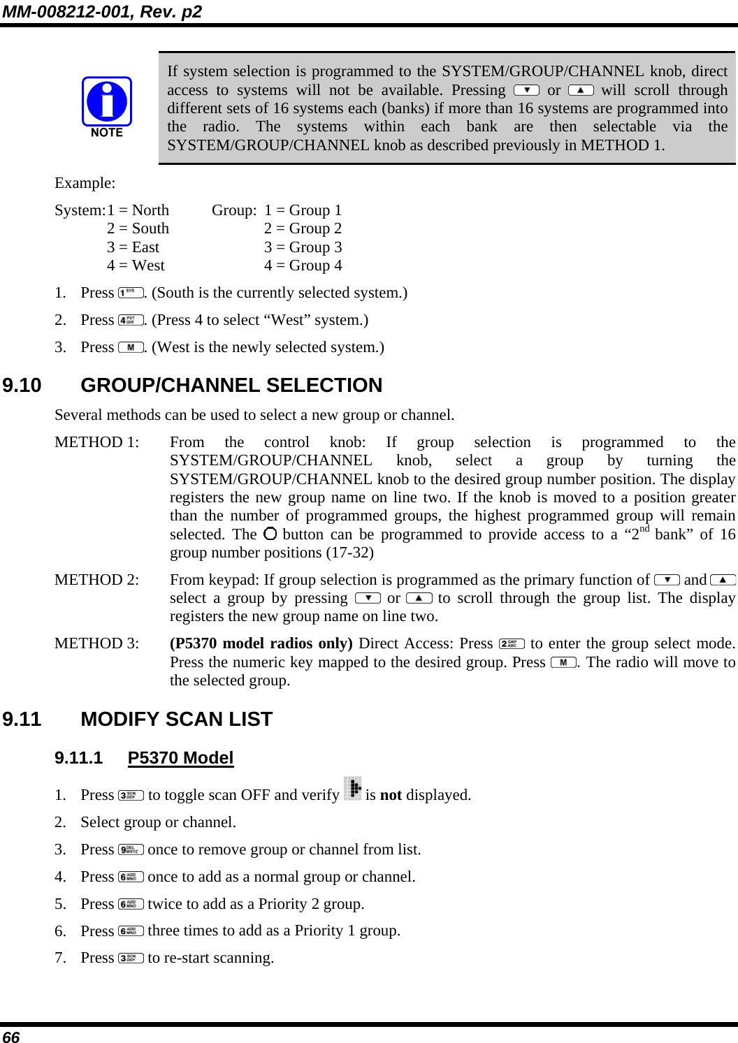
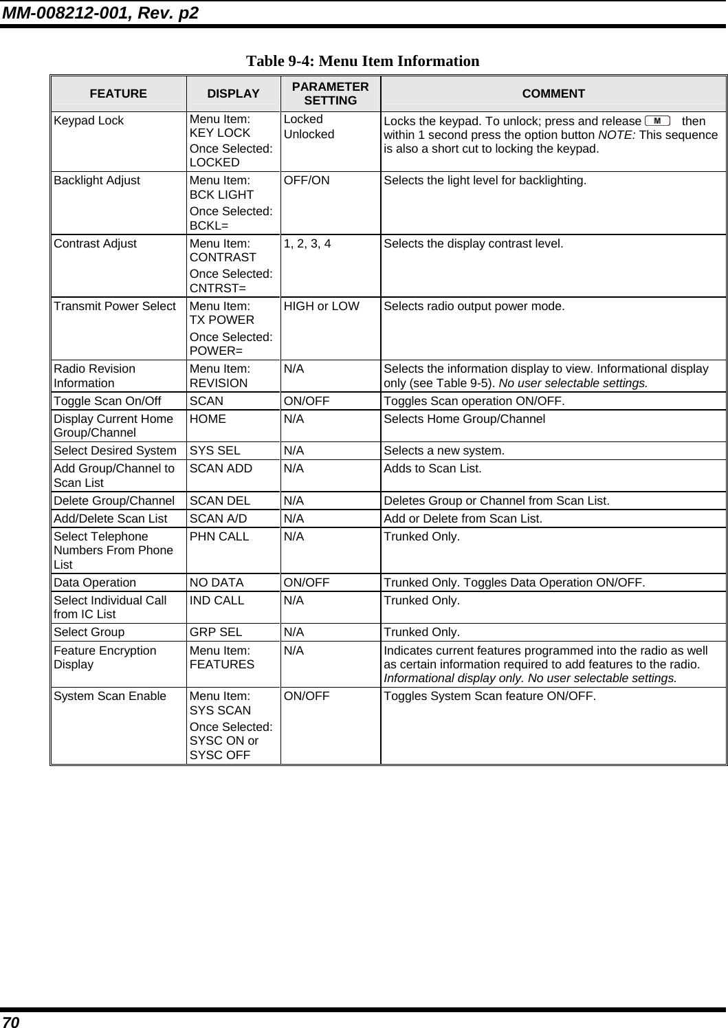
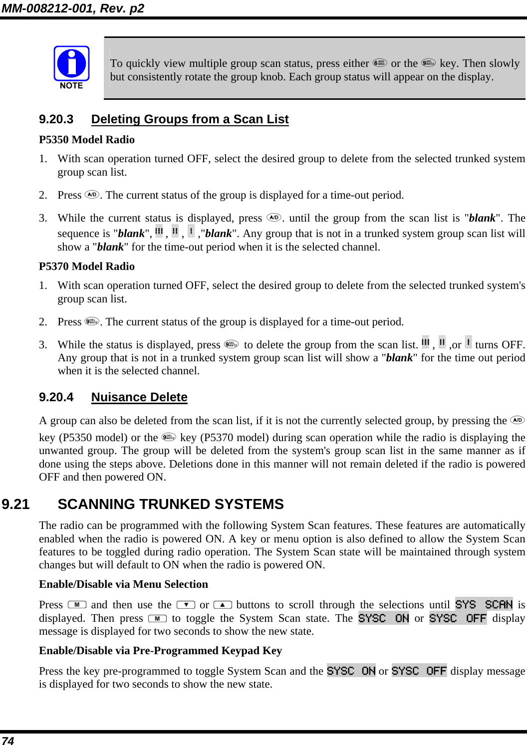
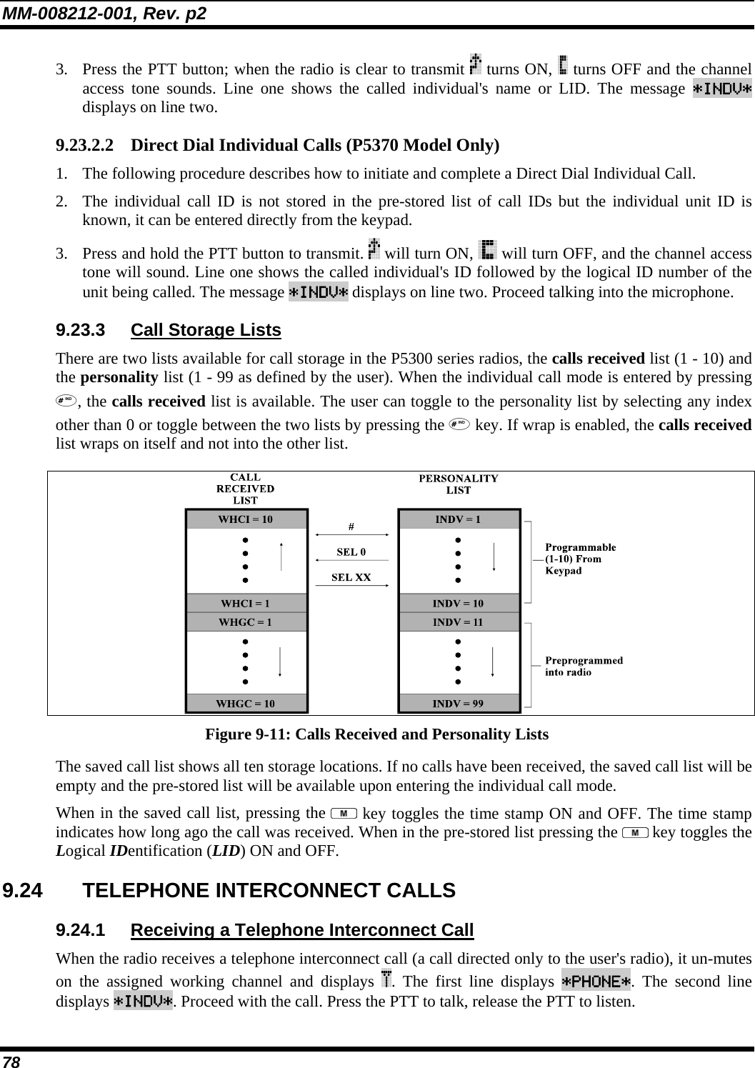
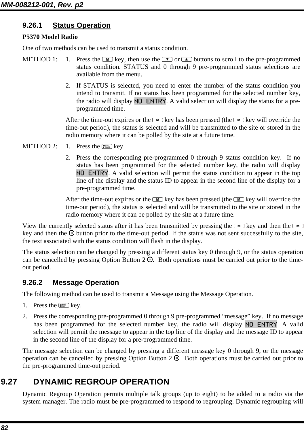
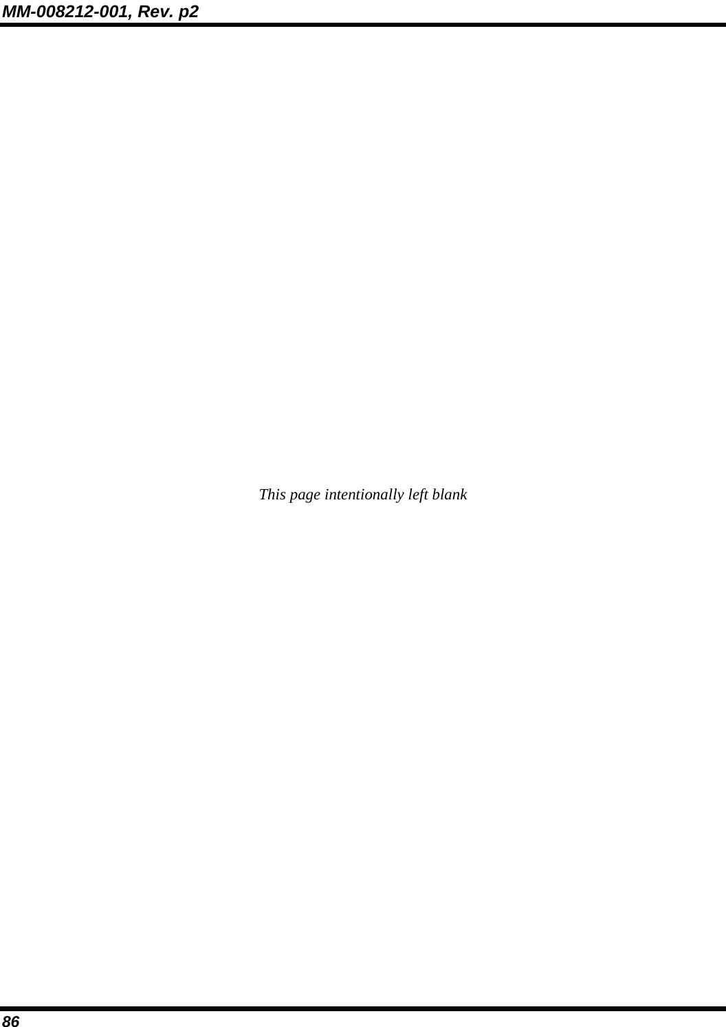
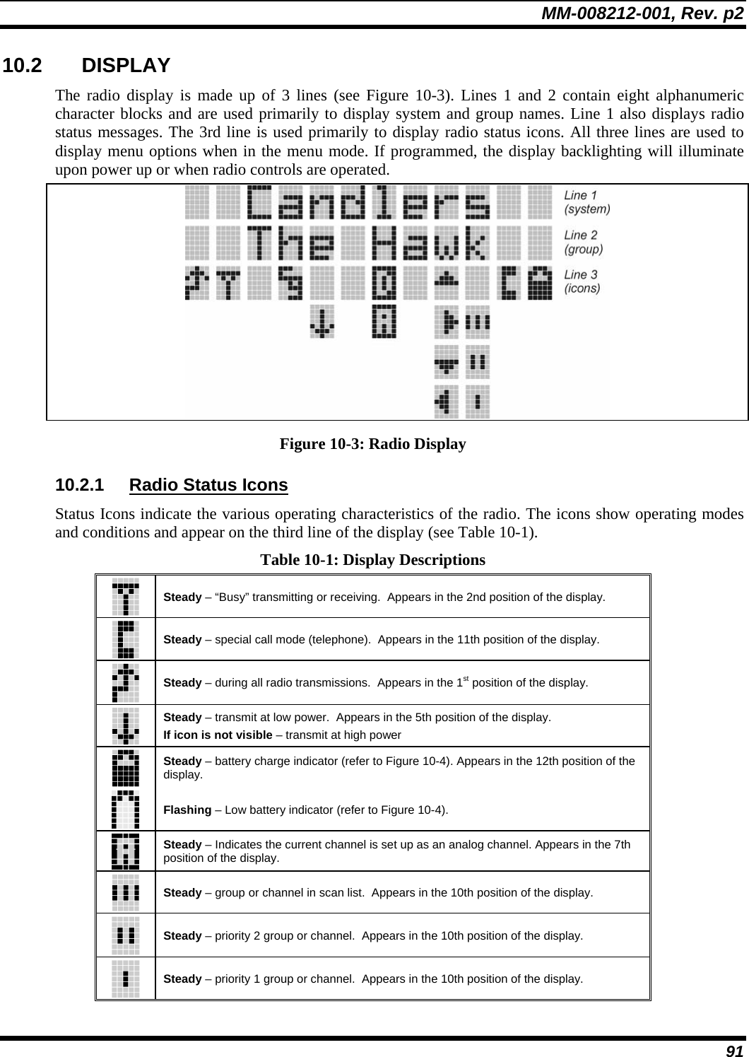
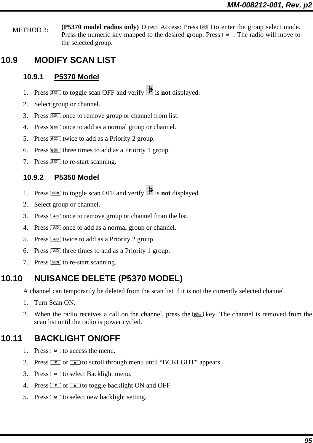
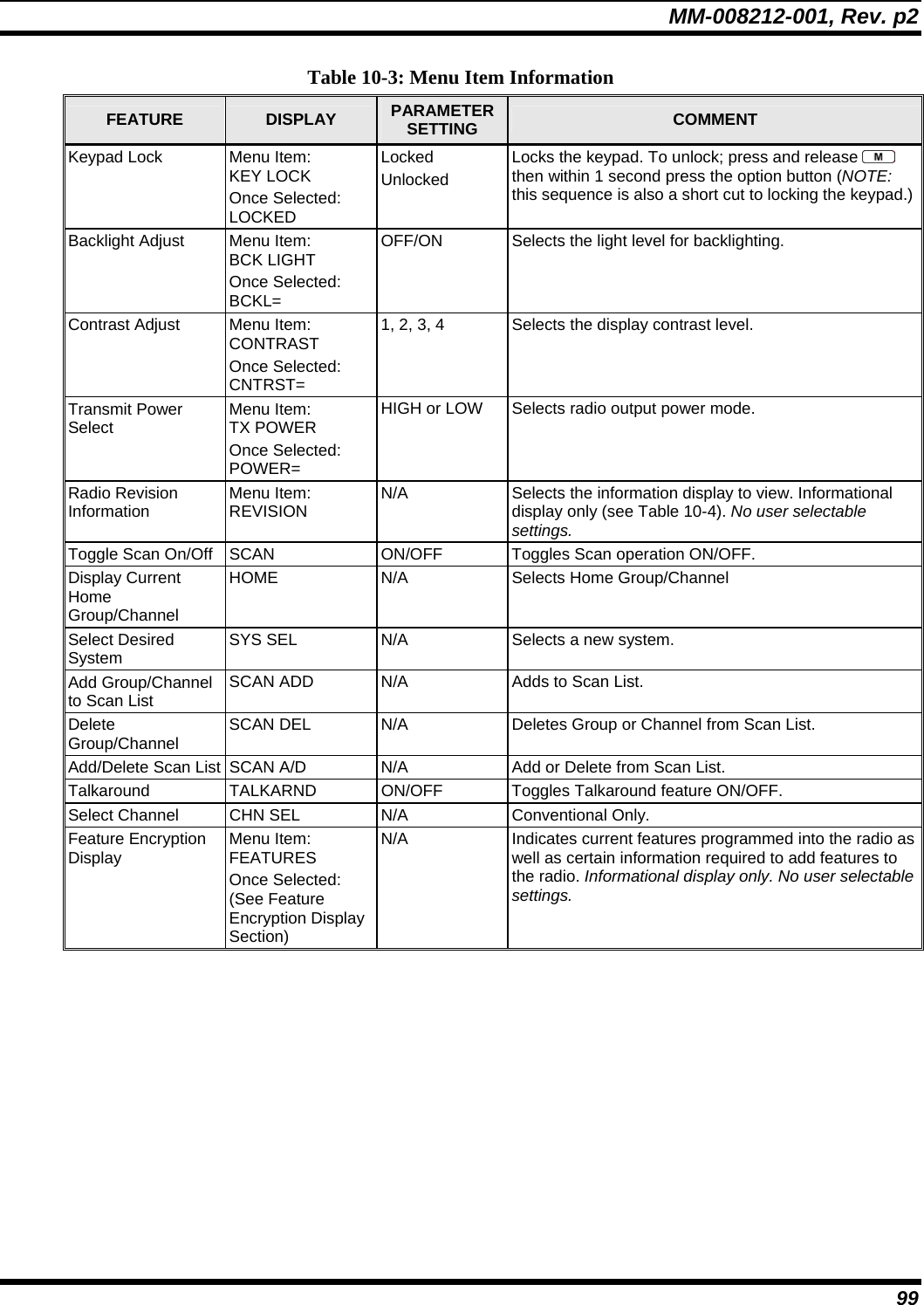
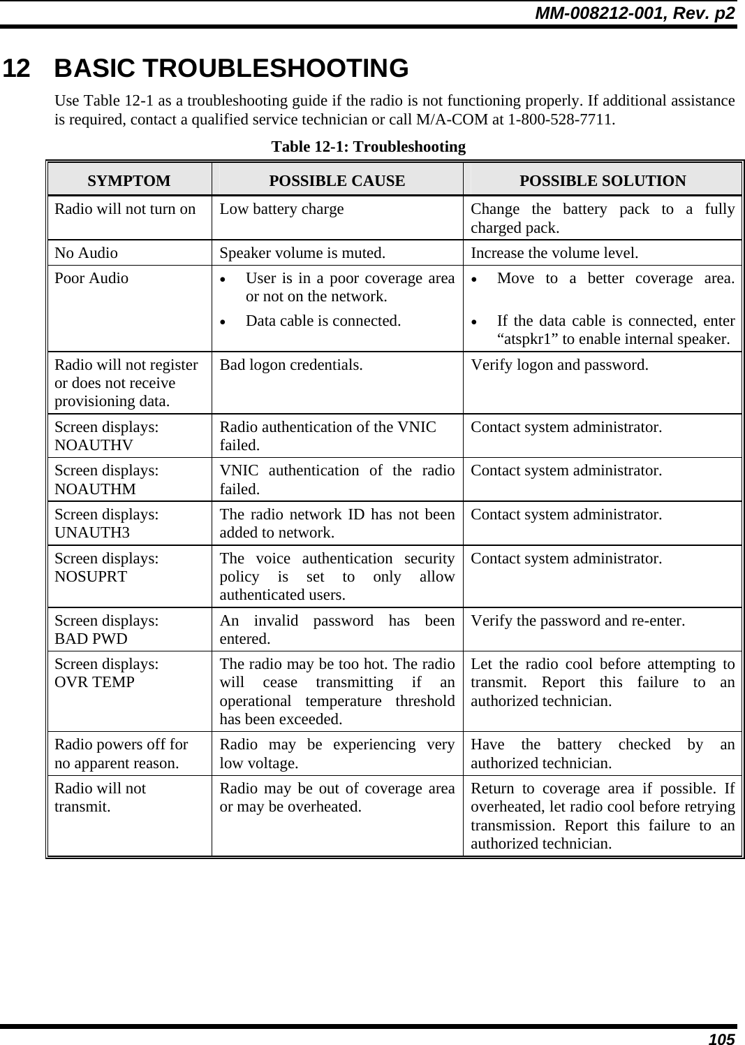
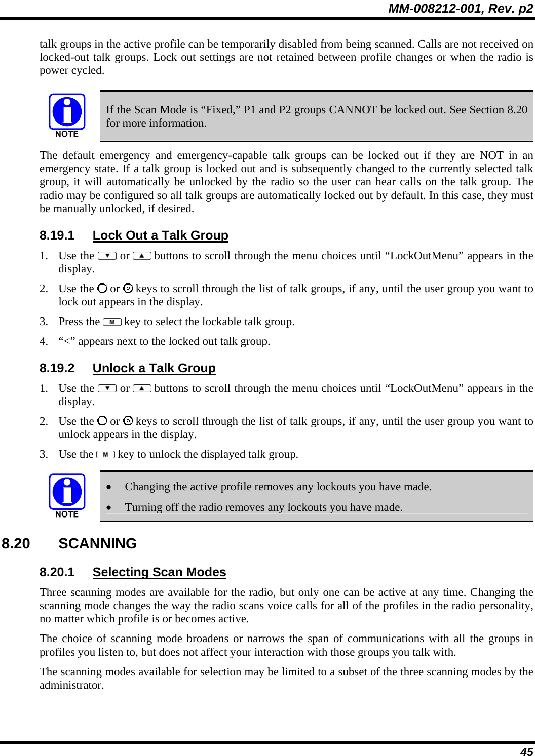
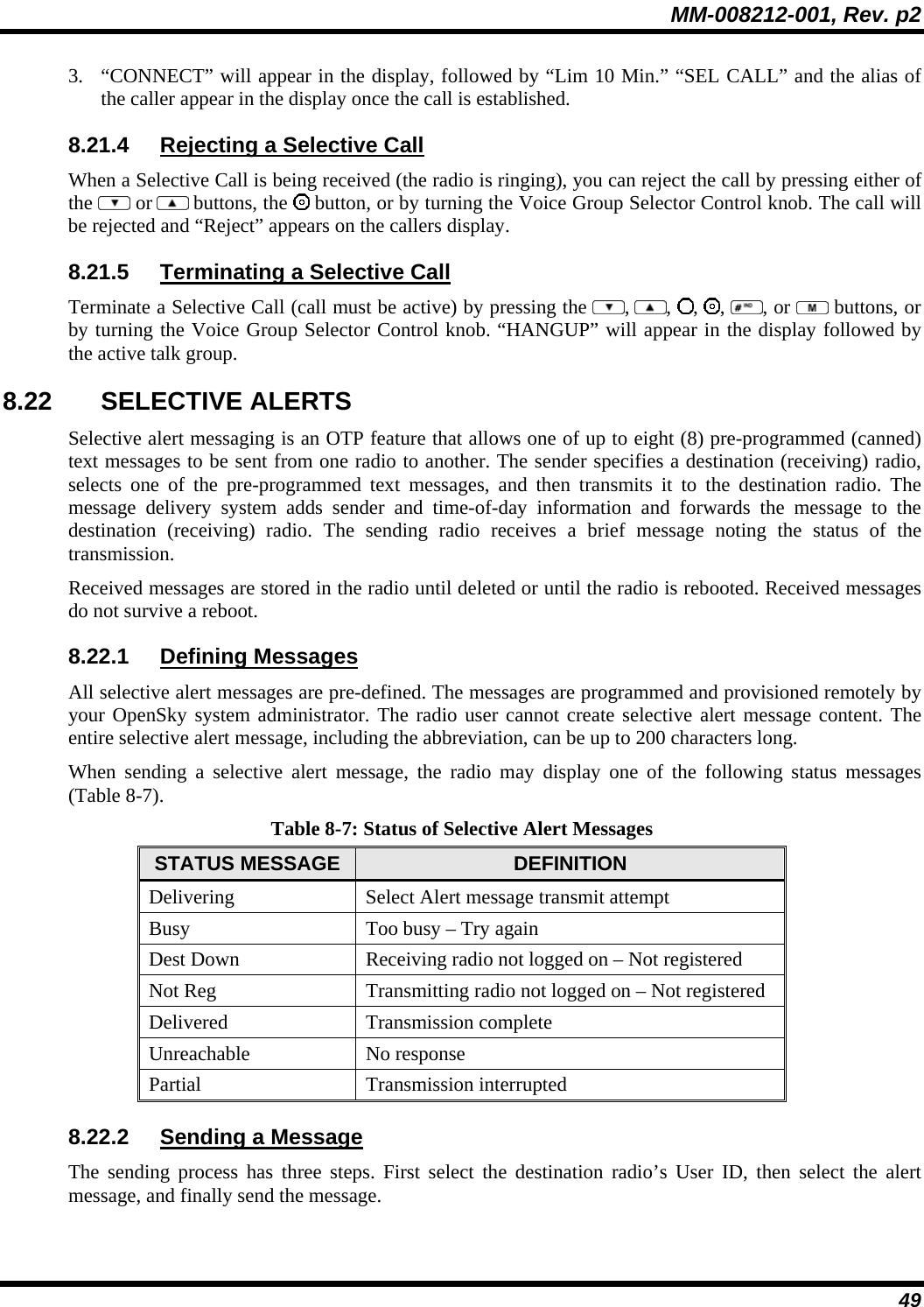
![MM-008212-001, Rev. p2 40 8.9 BASIC MENU STRUCTURE Table 8-4 illustrates the basic P5300 OpenSky menu structure. Menu items will vary depending upon system programming, radio hardware, and optional configurations. All menus except the dwell display menu can be turned off by network administration personnel. Table 8-4: Basic P5300 OpenSky Menu Structure Menu Name Radio Displays (first and second lines) Usage Notes To/From Dwell Display registration, RF sync and transceiver status codes Engineering Display (Menu may not be available per programming.) bit-error rates and RSSI data Displays radio system connection data. For engineering use. OFF/ON Silent Emergency “SilentEmerg” Use or to toggle between OFF/ON. Press to enable. available modes Operating Mode (e.g., OTP, OCF) “Mode Menu” Use or to choose an available mode. Press and confirm (Y/N) with or and again. current latitude and longitude (degrees:minutes:seconds) GPS Fix [e.g., GPS, GPS (Site), GPS (Aged)] “GPS” GPS latitude and longitude position of currently tuned-to base station [“GPS (Site)”] or V-TAC (“GPS”) scrolls across top line of the display. “GPS (Aged)” indicates VTAC coordinates haven’t been updated for more that 2 minutes. User ID # of user currently logged in User ID “User ID” User’s identification/name scrolls across top line of the display (if programmed). Radio’s IP address IP Address “IP Address” Radio’s Internet Protocol (IP) address scrolls across top line of the display. station’s call sign Station Identification “Station ID” Station’s identification/name scrolls across top line of the display (if programmed). “OFF” Stealth Mode (display backlight is disabled) “StealthMenu” Use or to turn on. Press any button to turn it off. “LOW”, “MEDIUM”, “MEDHIGH”, “HIGH” Treble Level “Treble Menu” Use or to choose speaker treble level. Press to return to dwell display. “<< >>” Display Brightness “Bright Menu” Use or to brighten or dim backlighting. Press to return to dwell display. “OFF”, “LOW”, “MED”, HIGH” Side Tone Level “Side Menu” Use or to choose side tone level. Press to return to dwell display. See Next Page](https://usermanual.wiki/HARRIS/TR-0047-E/User-Guide-794529-Page-41.png)
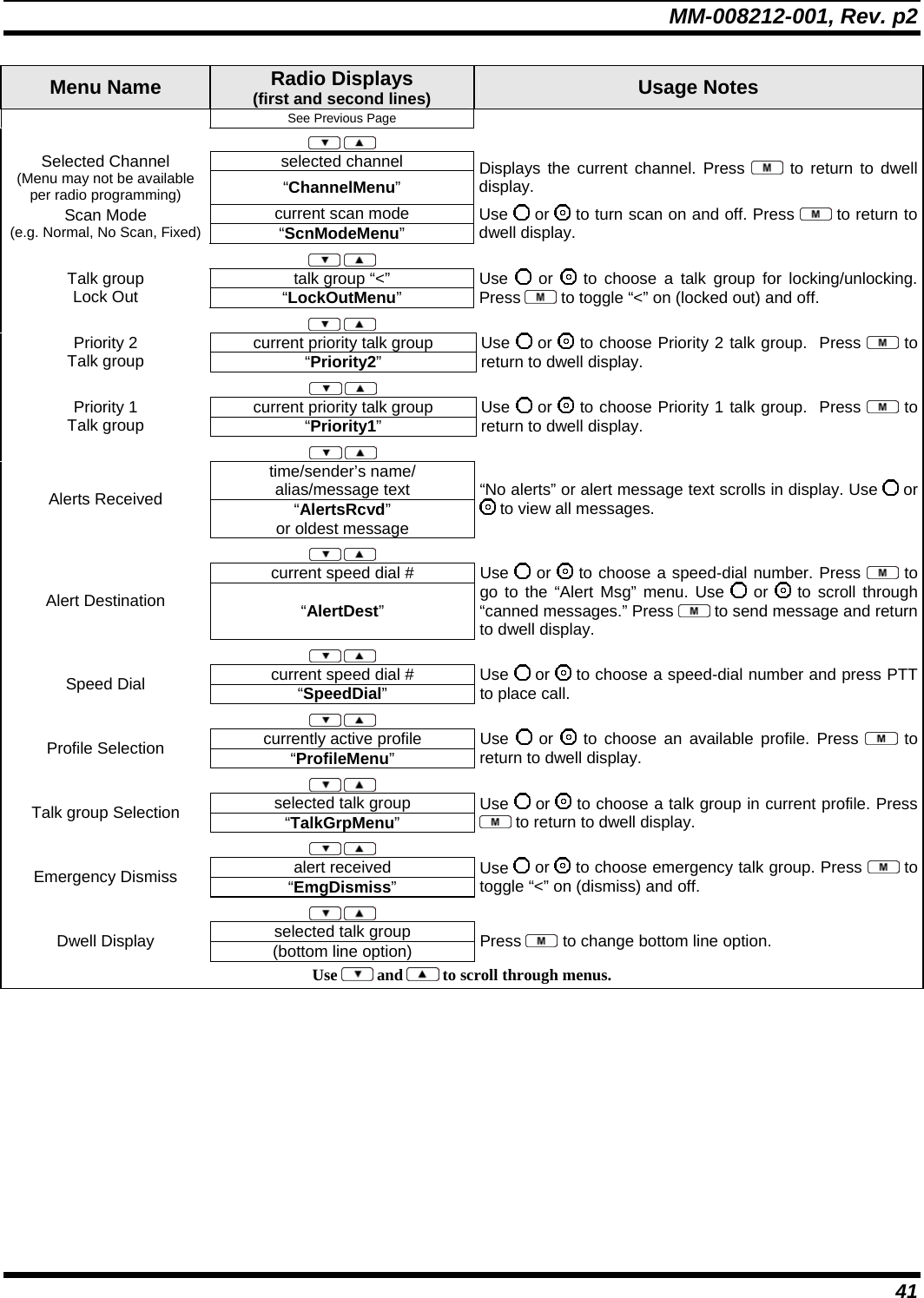
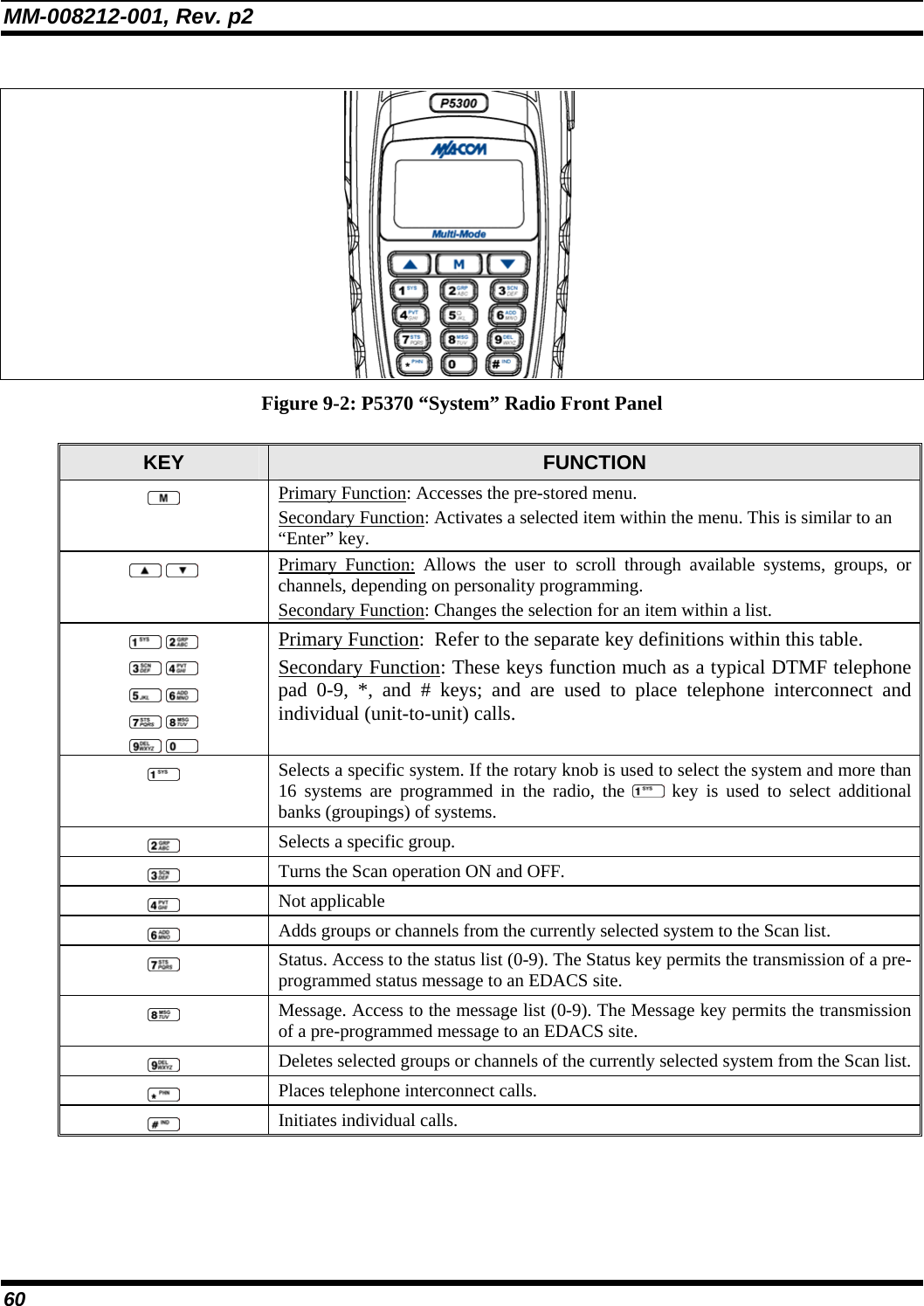
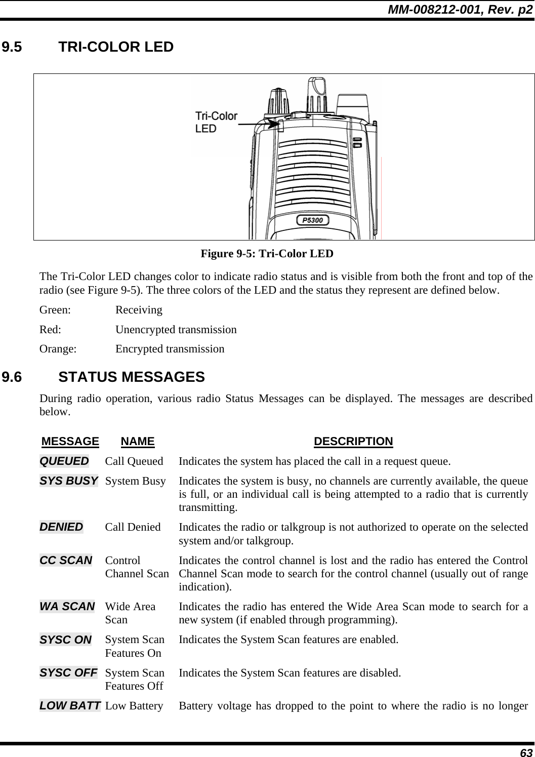
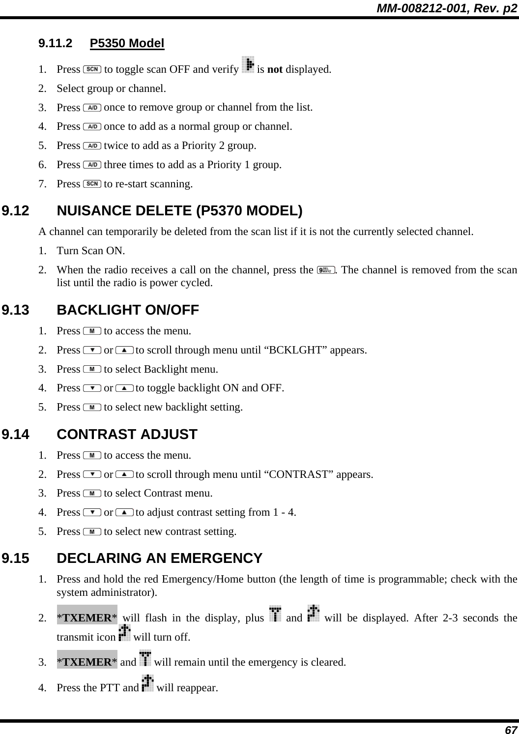
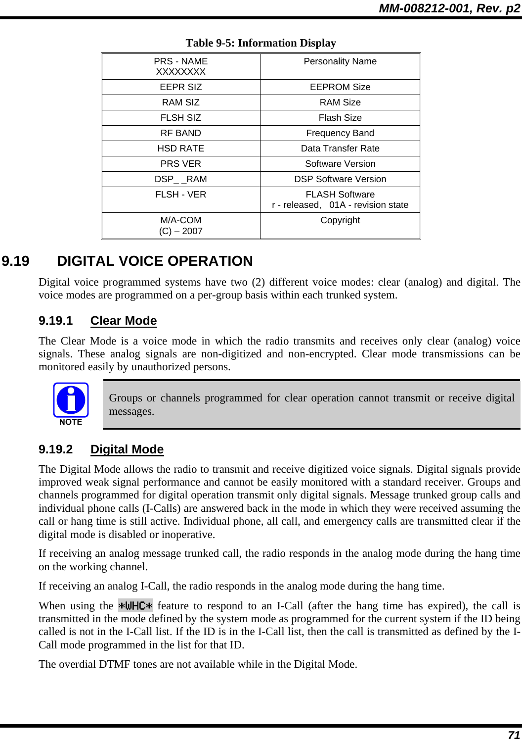
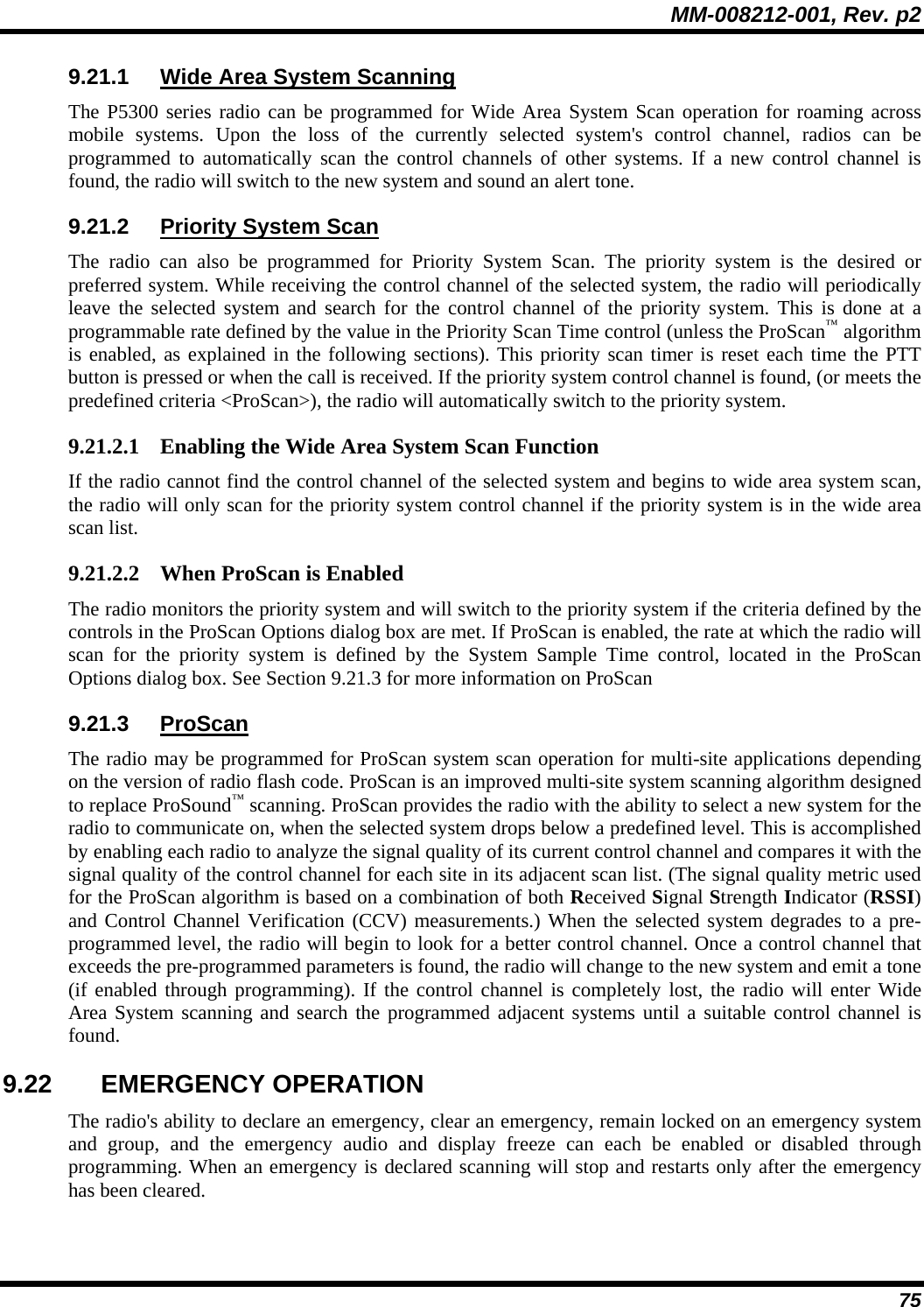
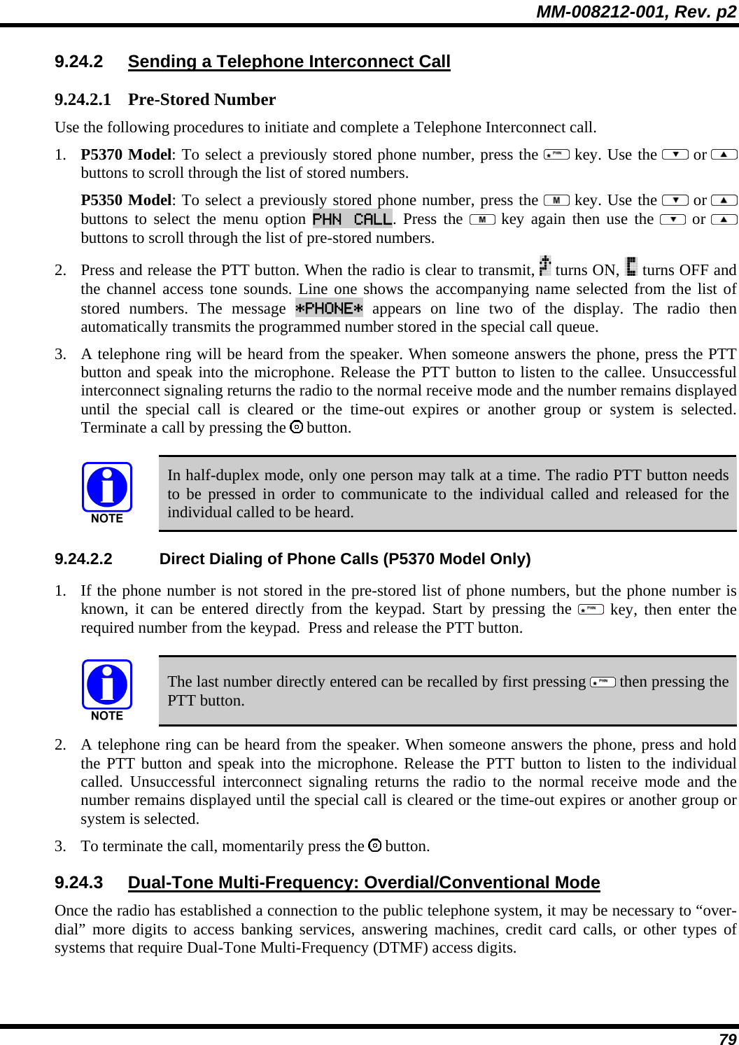
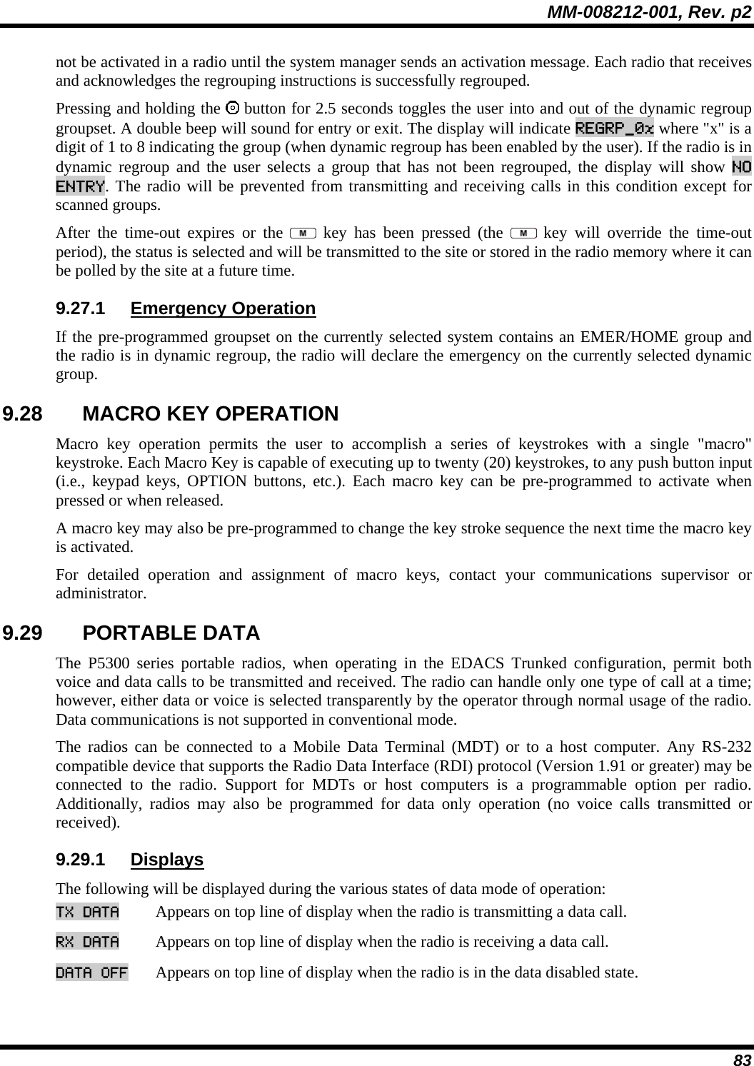
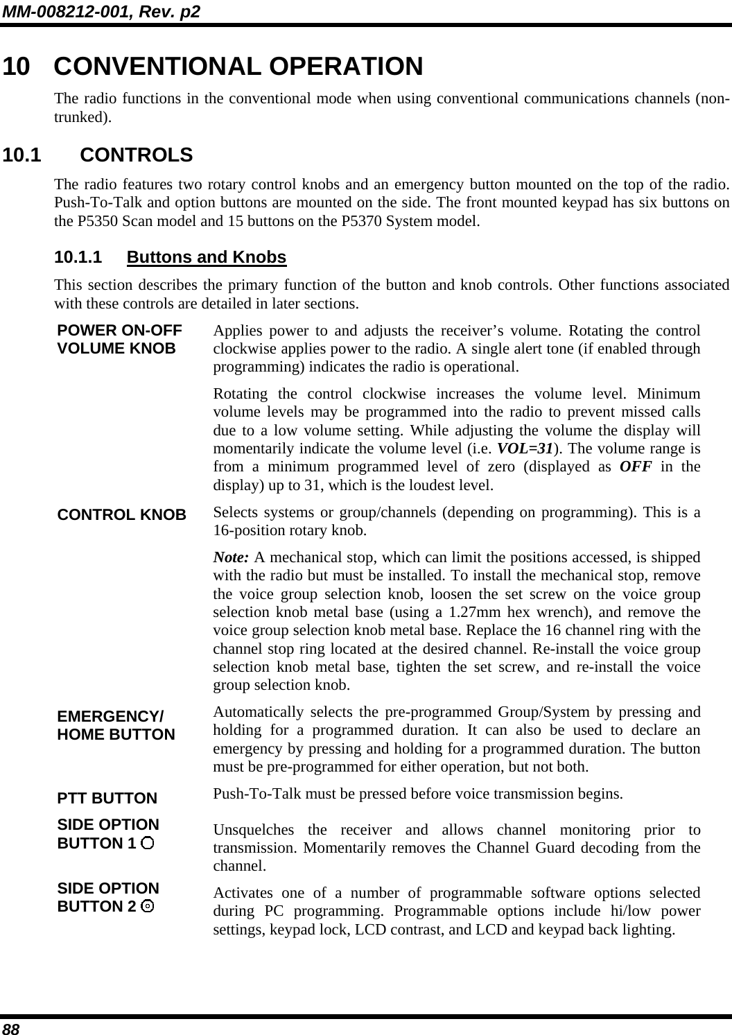
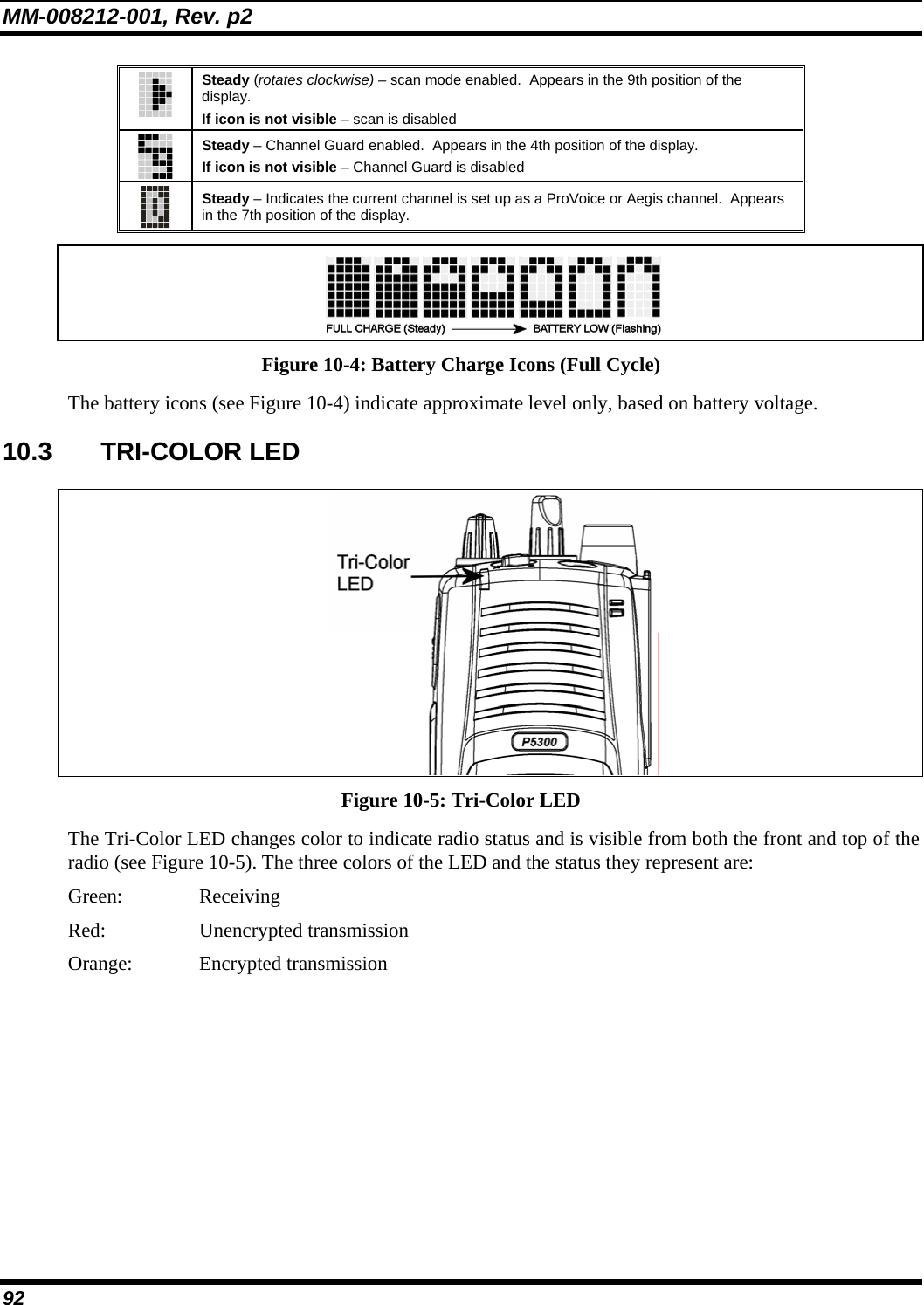
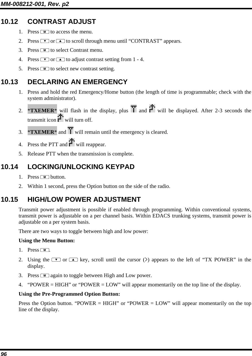
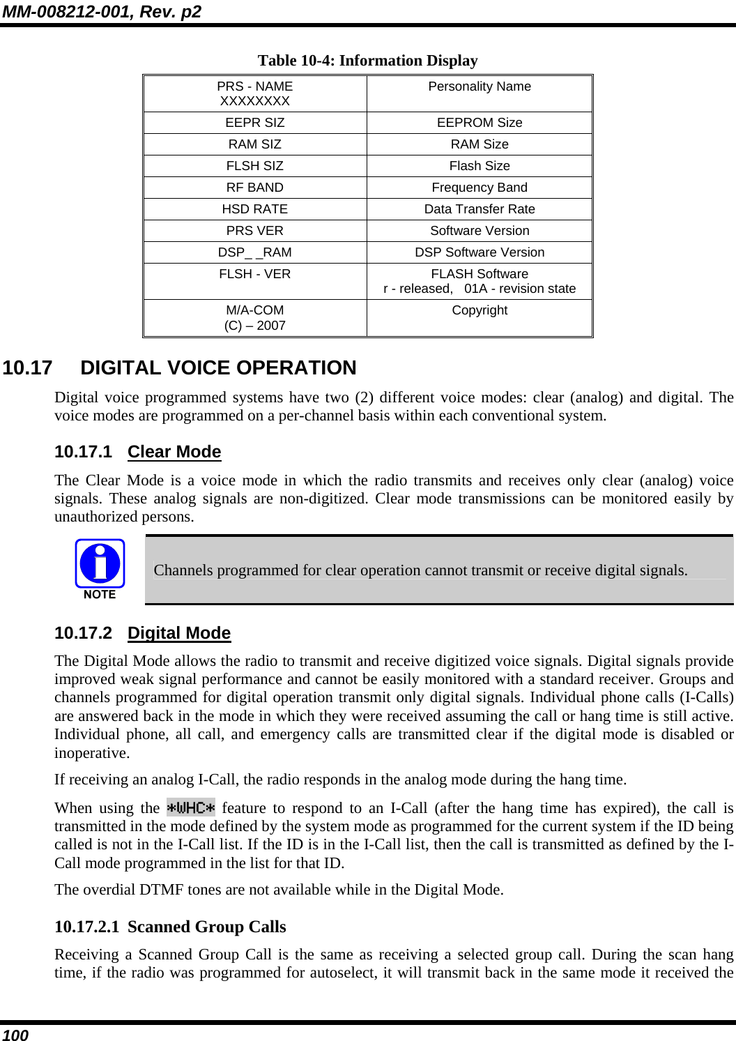
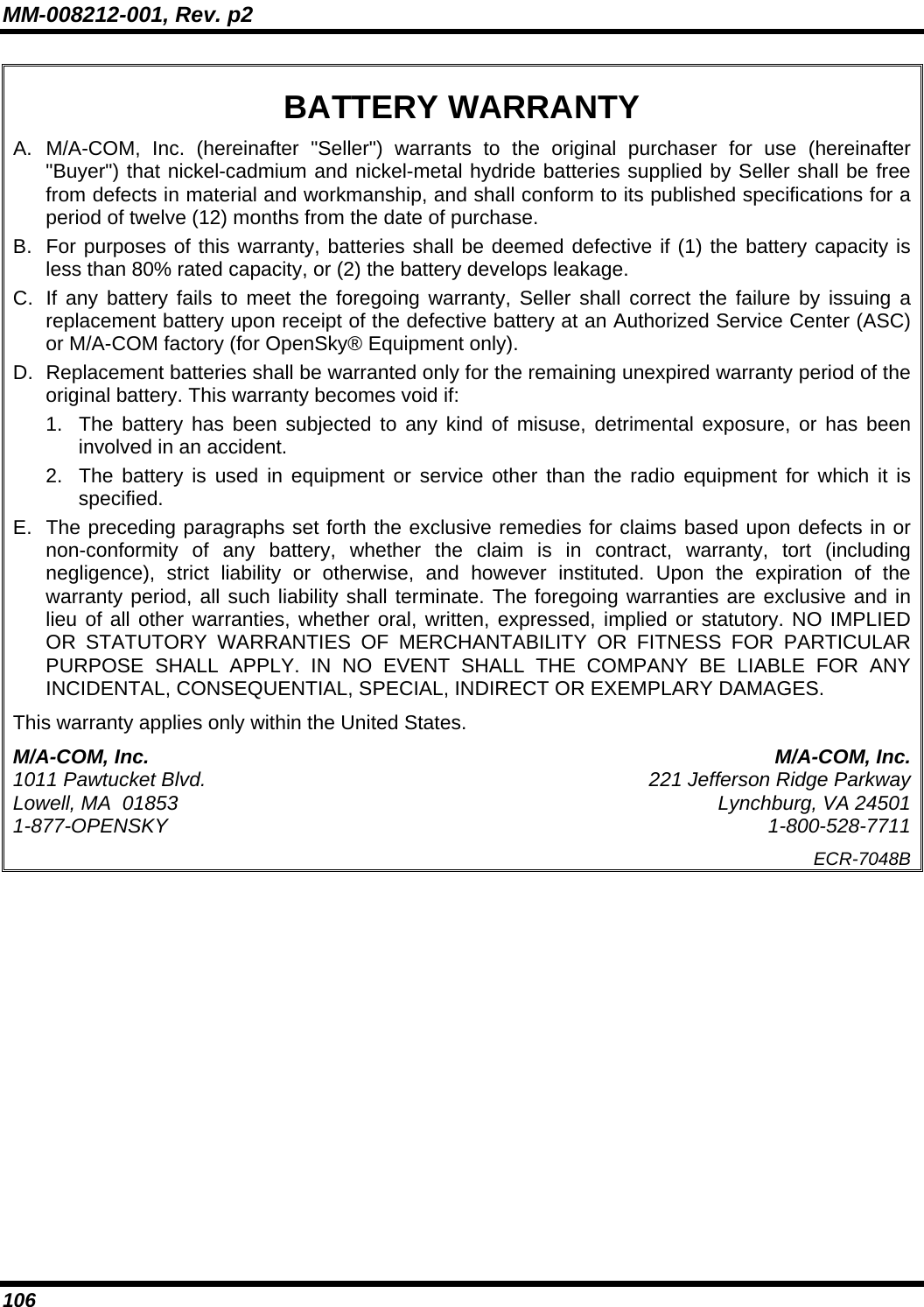
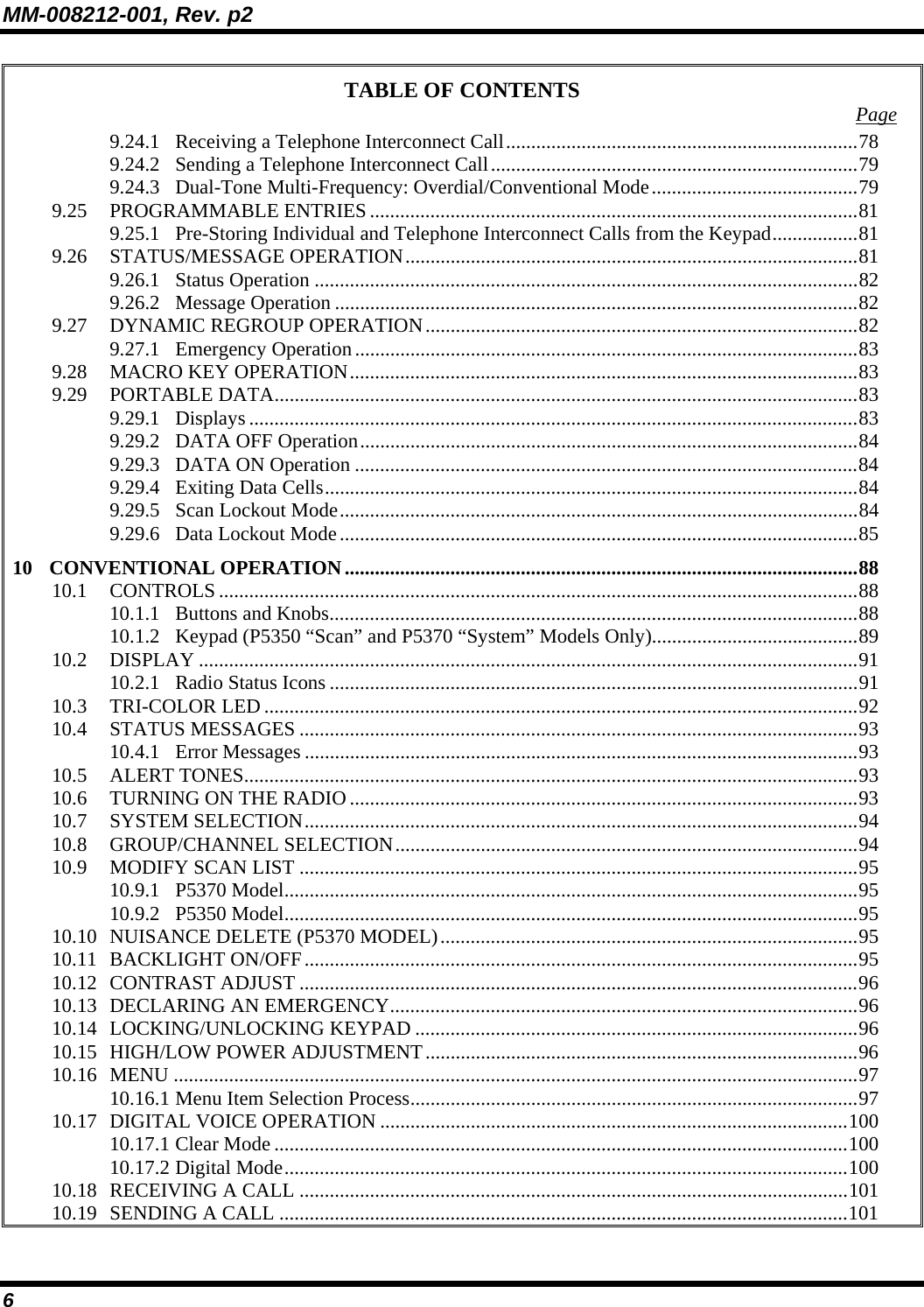
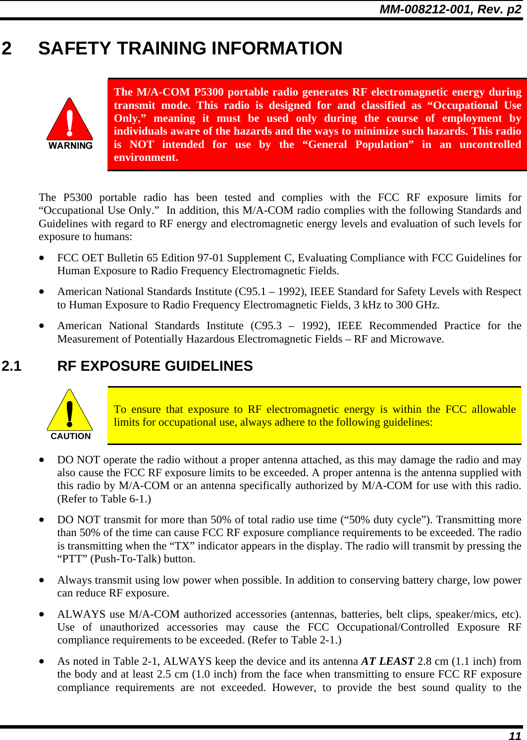
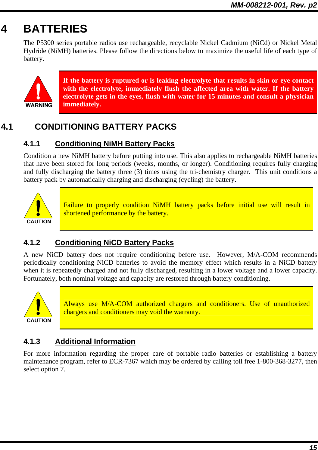
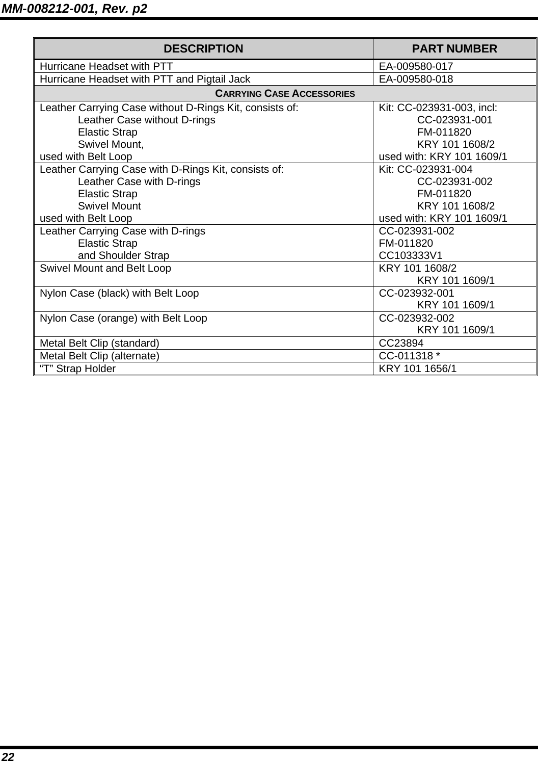
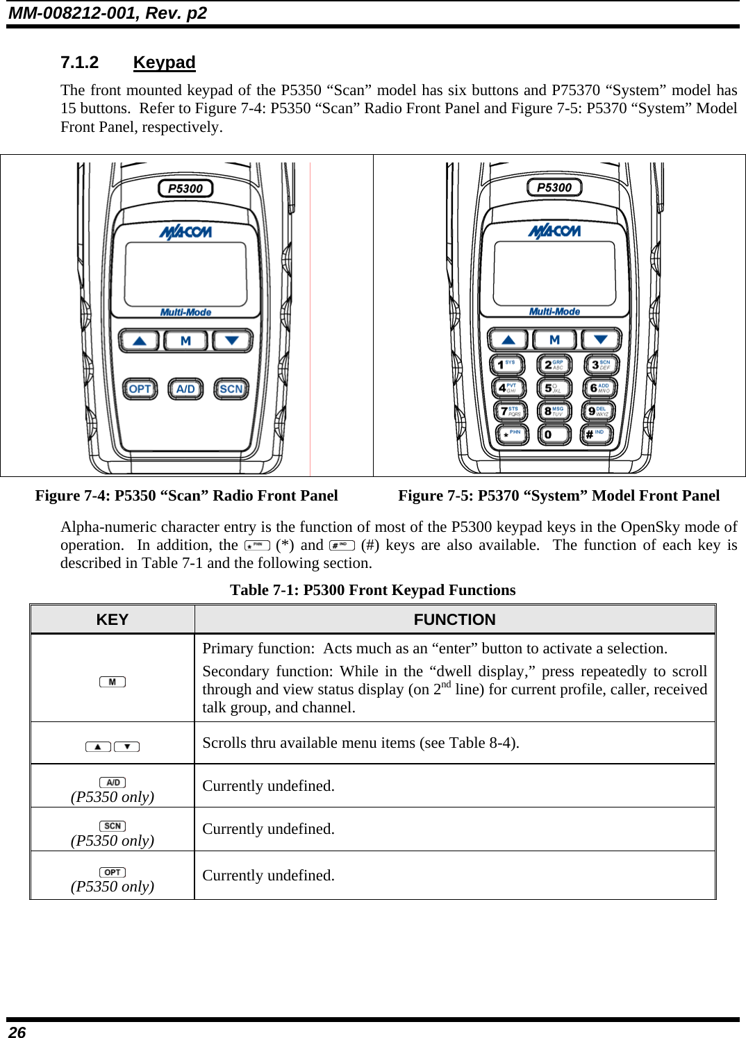
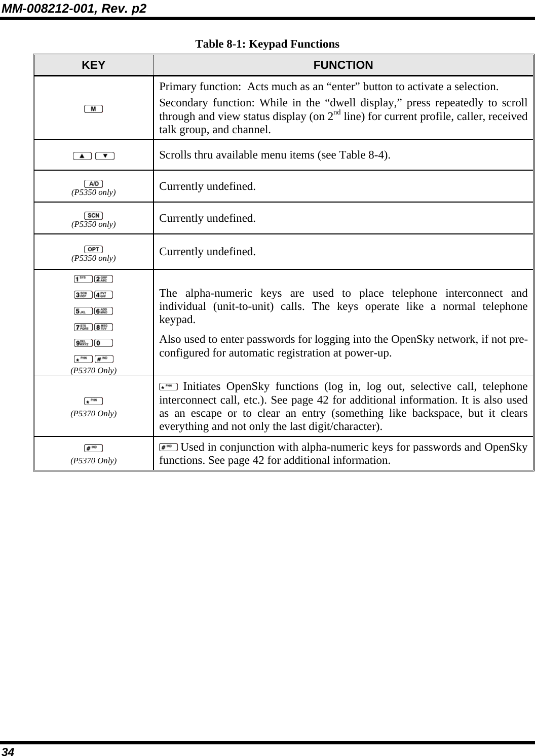
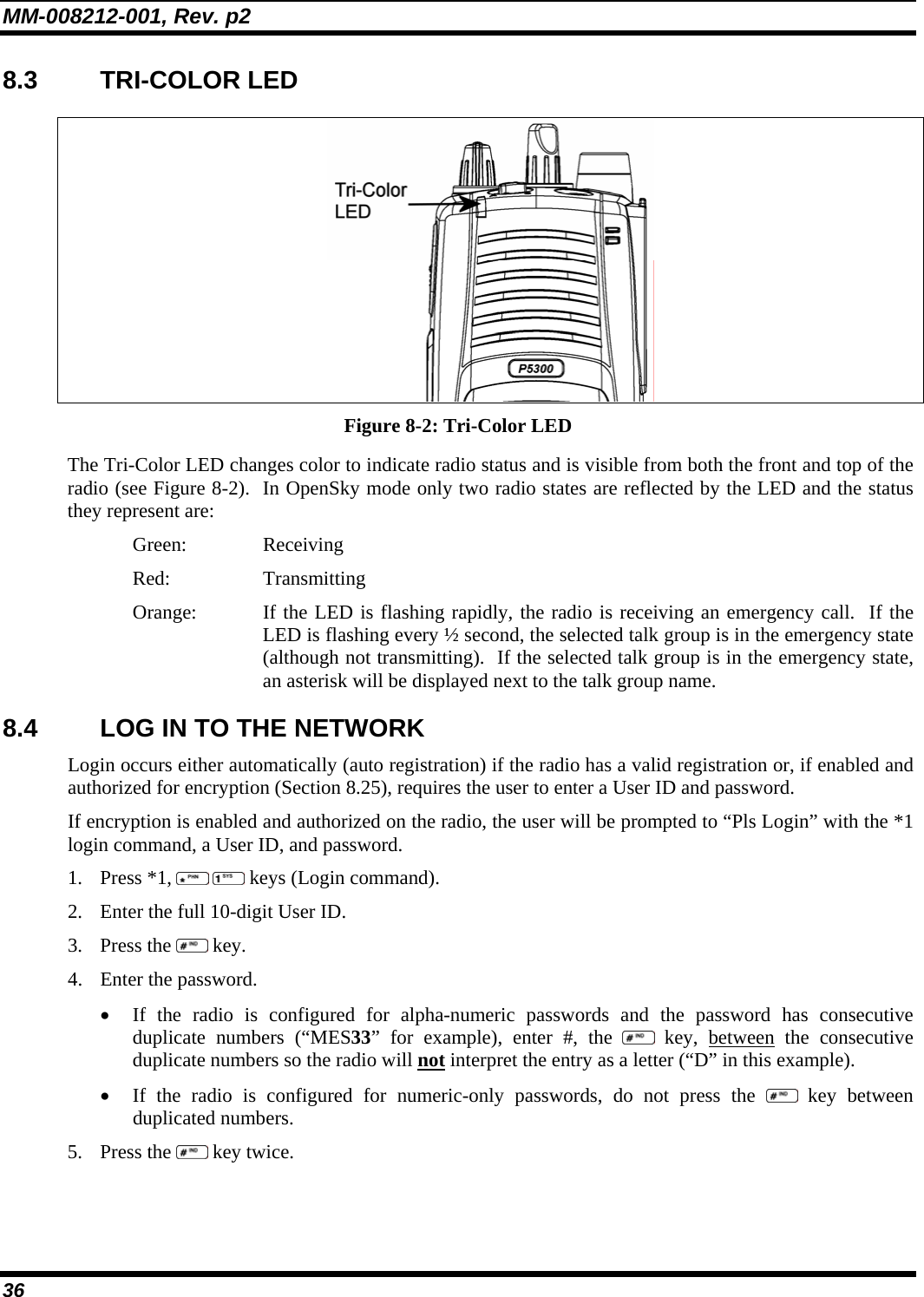
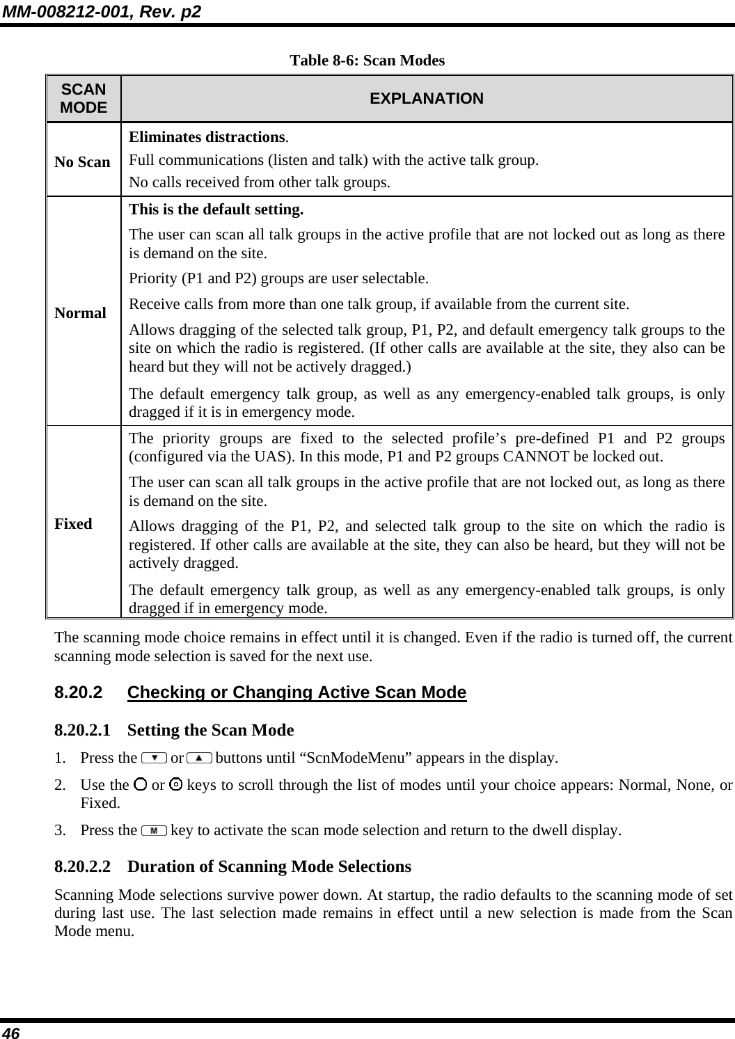
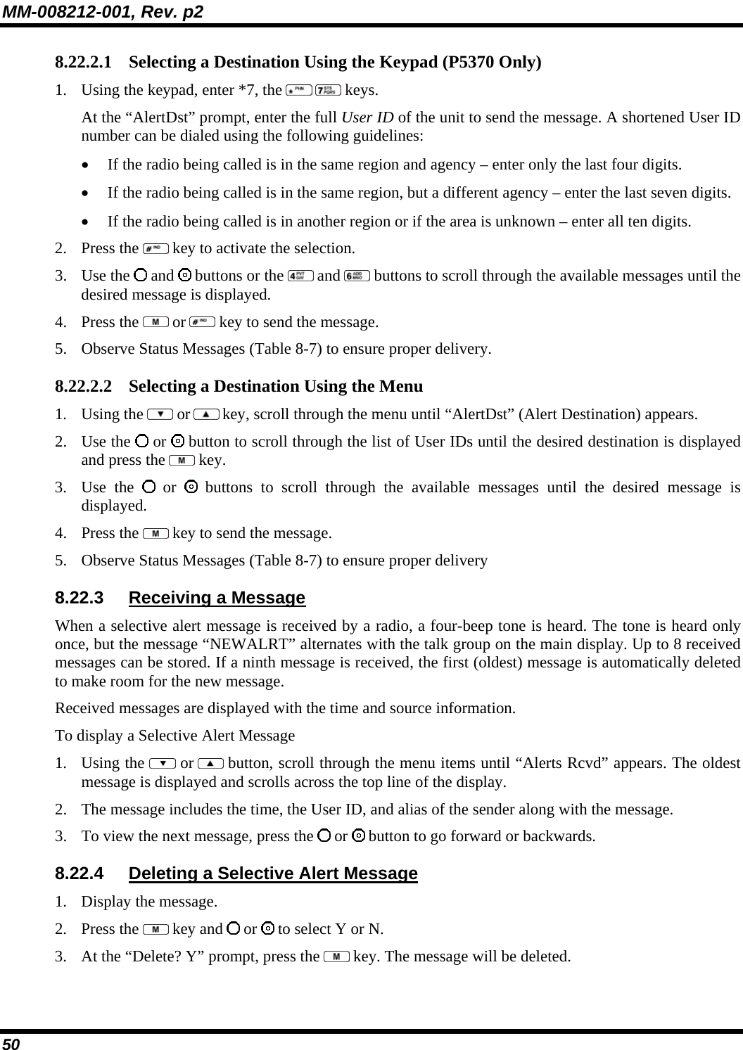
![MM-008212-001, Rev. p2 42 8.10 KEYPAD FUNCTION COMMANDS (P5370 ONLY) To perform a command from the keypad, use the keypad commands in Table 8-5. Table 8-5: Keypad Function Commands *0 Log-off command: *0## (logs the user off the system). See Section 8.5 for additional information. Key presses: *1 Log-in command: *1<User ID> # <Password> ## (required for encryption). See Section 8.2 for additional information. Key presses: <User ID> <Password> *4 SOI Mode: User is prompted with a channel to communicate with using the default profile. Exit SOI Mode with *4# Key presses: *7 Initiate Selective Alert command: *7<Target ID>#[Choose Message]#. See Section 8.22 for additional information. Exit SOI Mode with *4#. Command: *8 Radio-to-Radio Call command: *8<Selective call number>#(PTT to dial). Command: <Selective call number> then press PTT to dial *9 Public Switched Telephone Network (PSTN) Call command: *9 <telephone number>#(PTT to dial) See Section 8.23 for additional information. Command: <telephone number> then press PTT to dial *32 Begin Manual Encryption command: *32<Pre-determined Encryption Key># 1 – 16 digit encryption key for 128 bit encryption; 17 –32 digit encryption key for 256 bit encryption. See Section 8.25 for additional information. Command: <pre-determined encryption key> *33 End Manual Encryption command: *33 Command: *61 Initiate XCOV Mode: Extended coverage for individual users. *62 Initiate XCOV-TG Mode: Extended coverage for talk groups. *60 Exit XCOV or XCOV-TG Mode: Returns to the normal mode. 8.11 CHANGING THE ACTIVE PROFILE The radio can store up to sixteen (16) standard profiles, one of which is the currently active profile. To change the currently active profile: 1. Press the or buttons until “ProfileMenu” is displayed. 2. Use or to scroll through the list of available profiles. 3. Profile becomes active when selected for longer than 2 seconds, when the is pressed, or when the menu is changed using the or button. Press to activate the selected profile. 8.12 CHANGING THE SELECTED TALK GROUP Each profile stored in the radio can have up to sixteen (16) talk groups. One talk group within the currently active profile is set as the “selected talk group.” To change the selected talk group, turn the Group Selection knob on top of the radio. 8.13 ADJUSTING DISPLAY AND BUTTON BACKLIGHT BRIGHTNESS 1. Press the or buttons until “Bright Menu” is displayed. 2. Use or to brighten or dim the display and button backlighting.](https://usermanual.wiki/HARRIS/TR-0047-E/User-Guide-794529-Page-43.png)
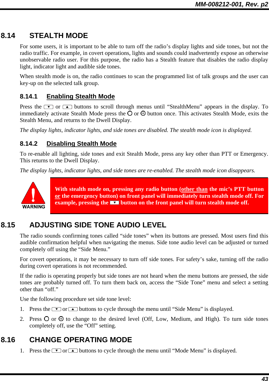
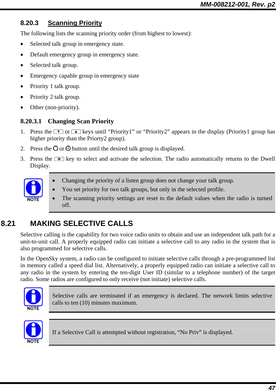
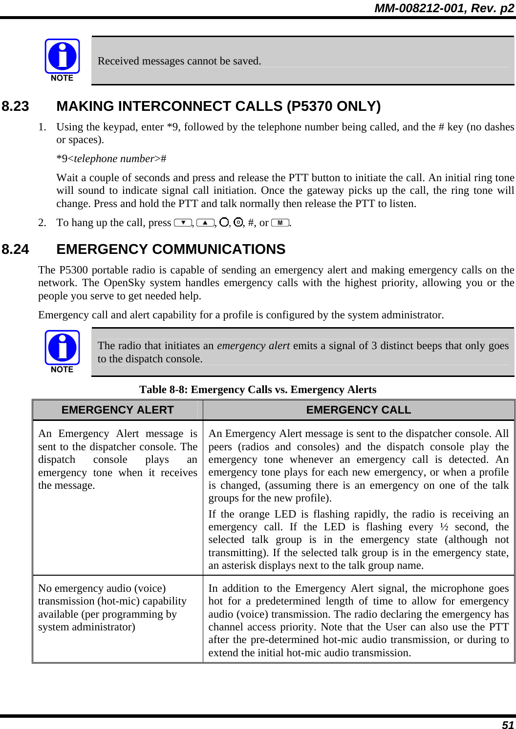
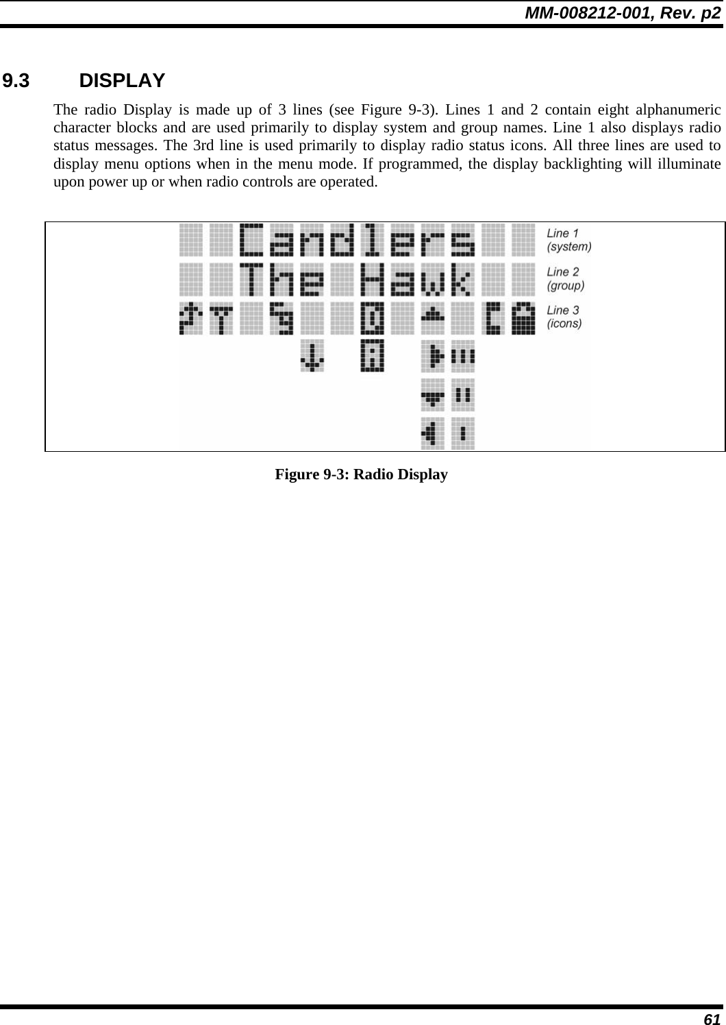
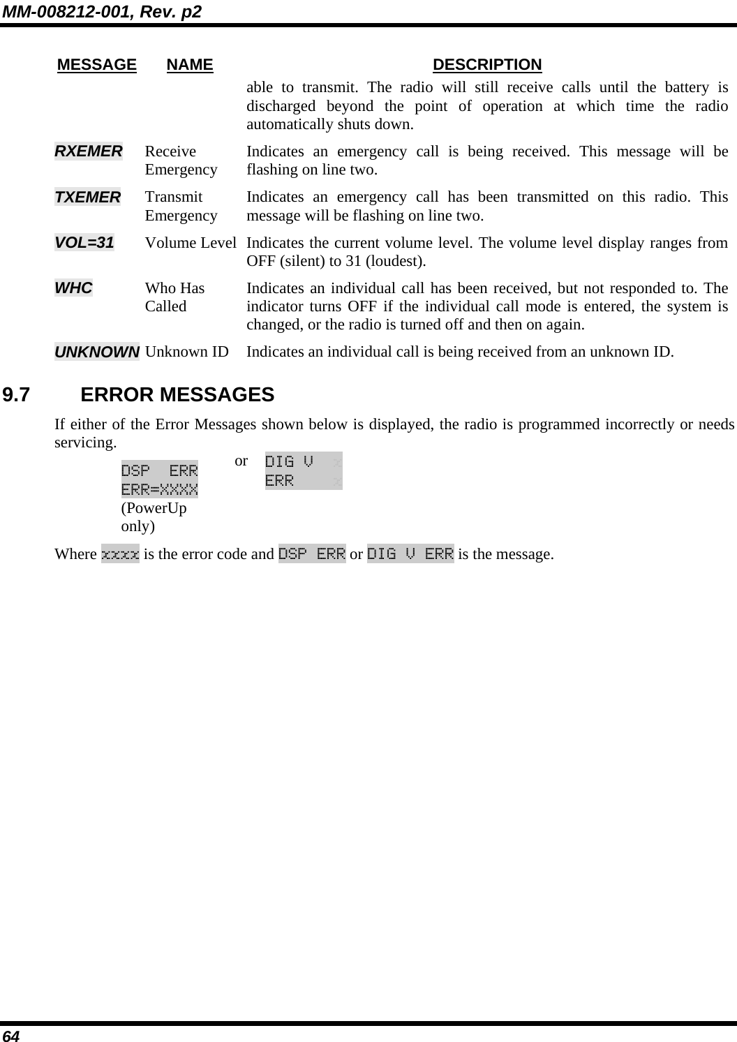
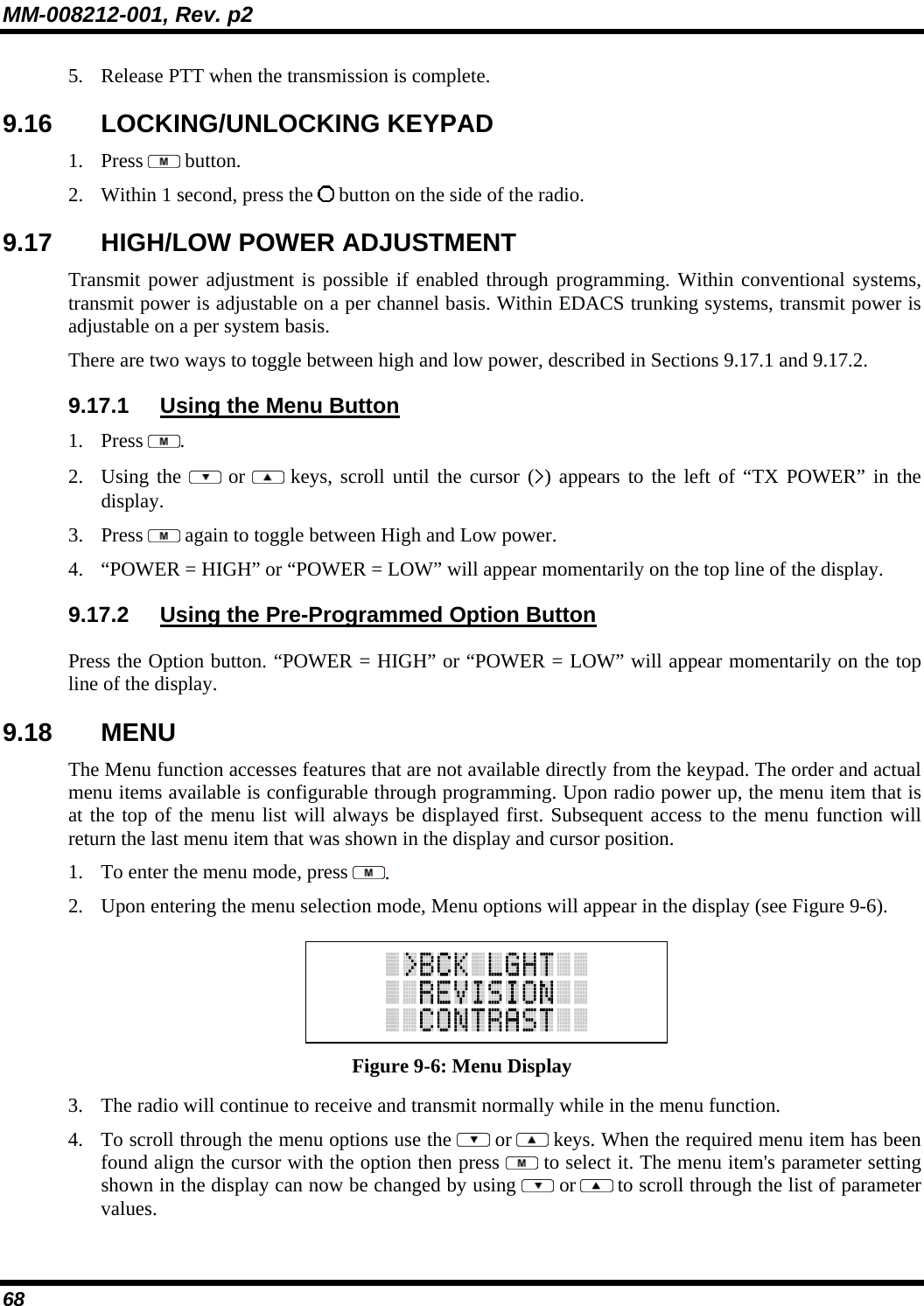
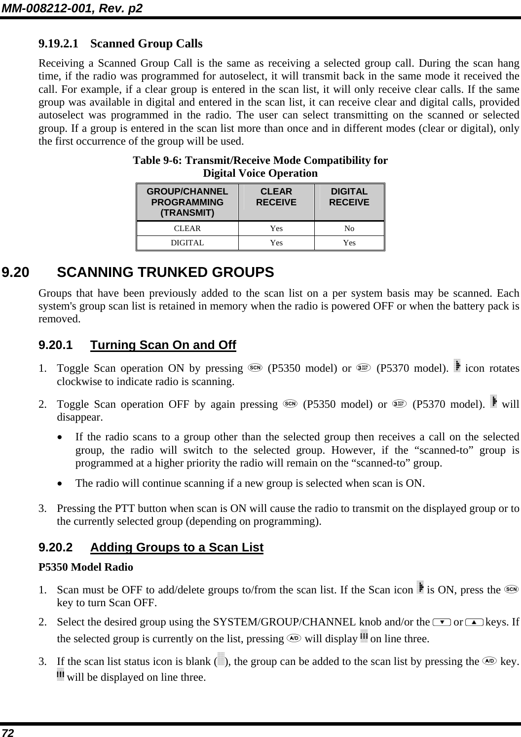
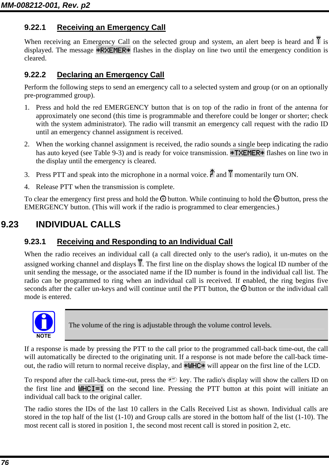
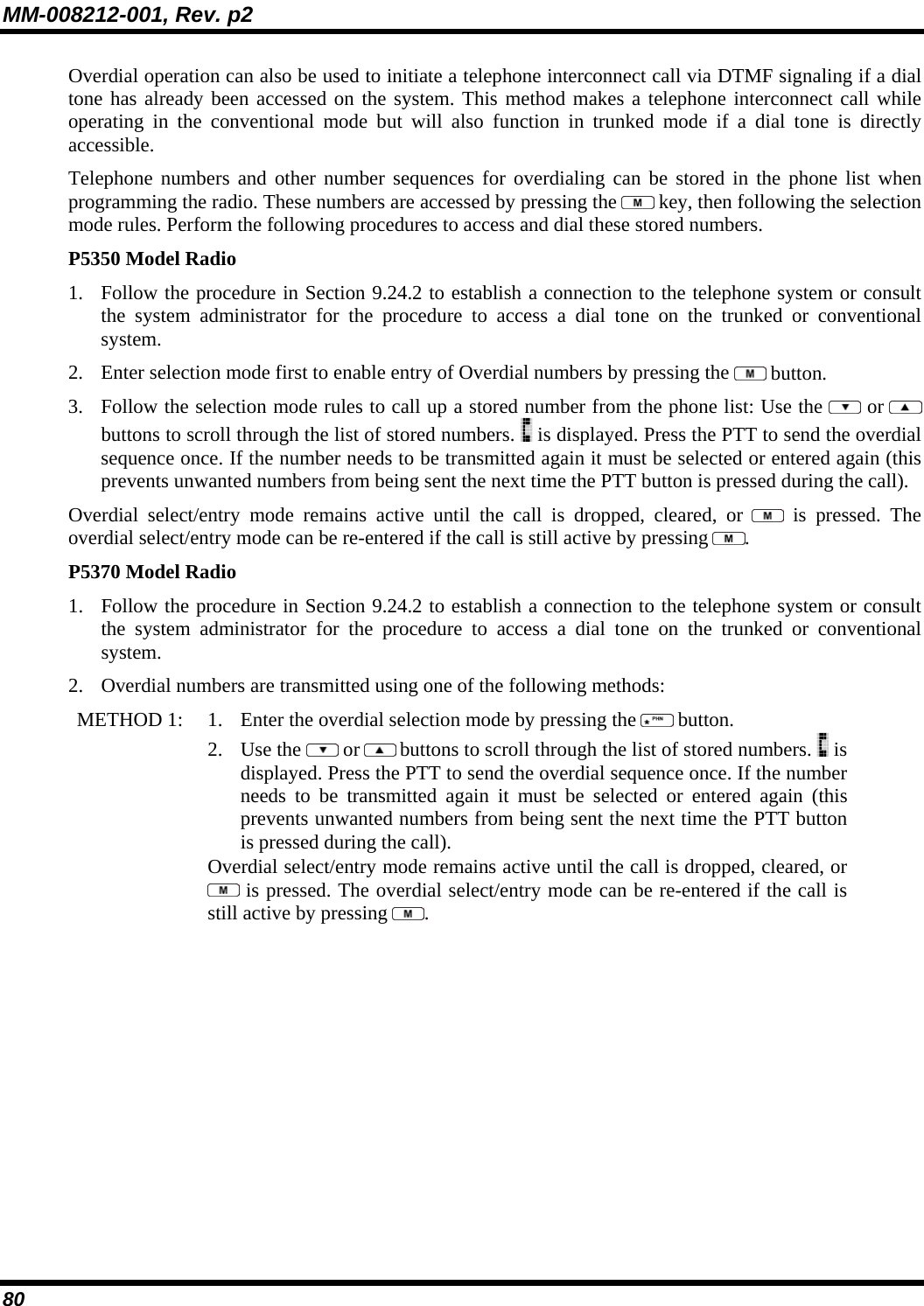
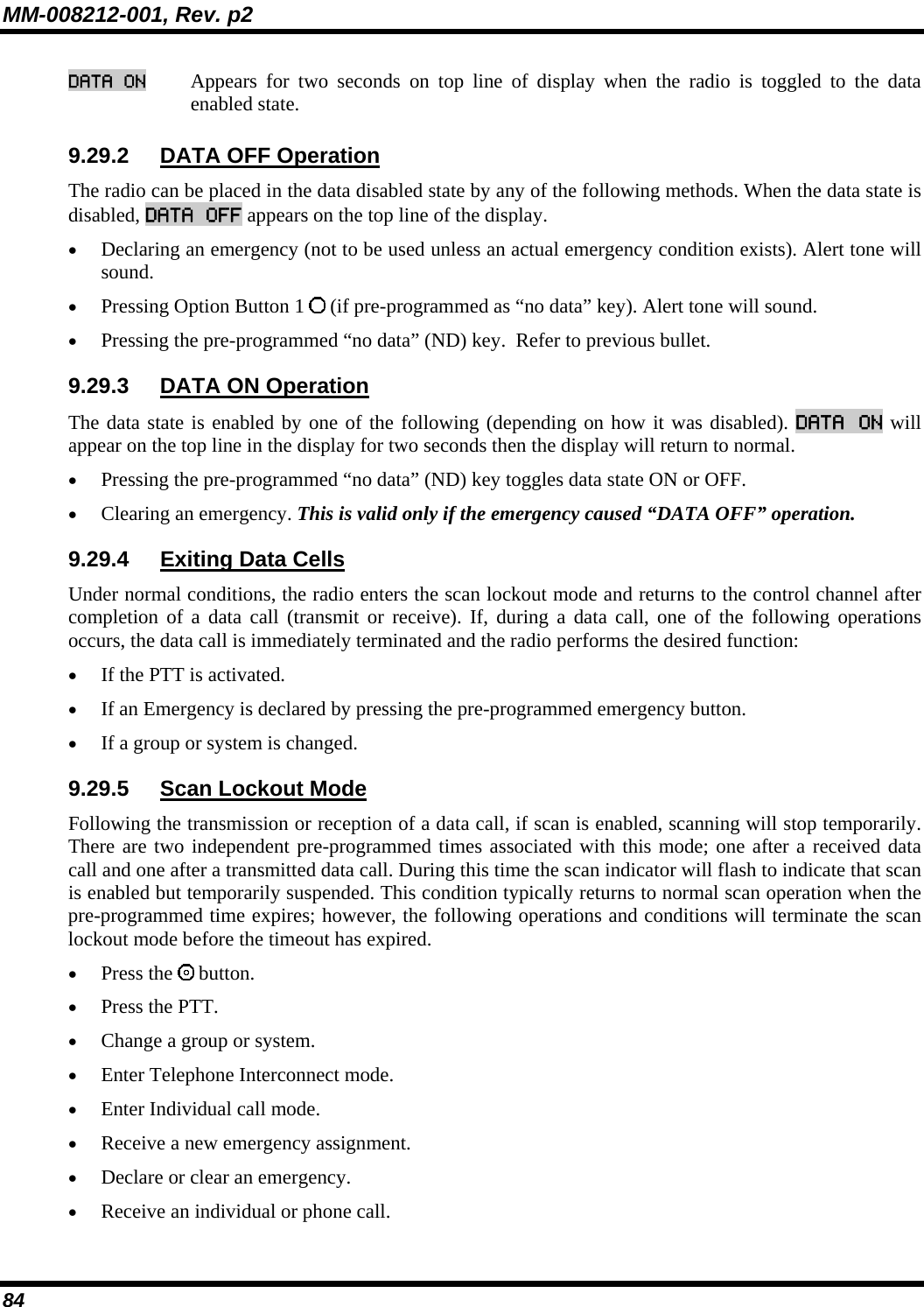
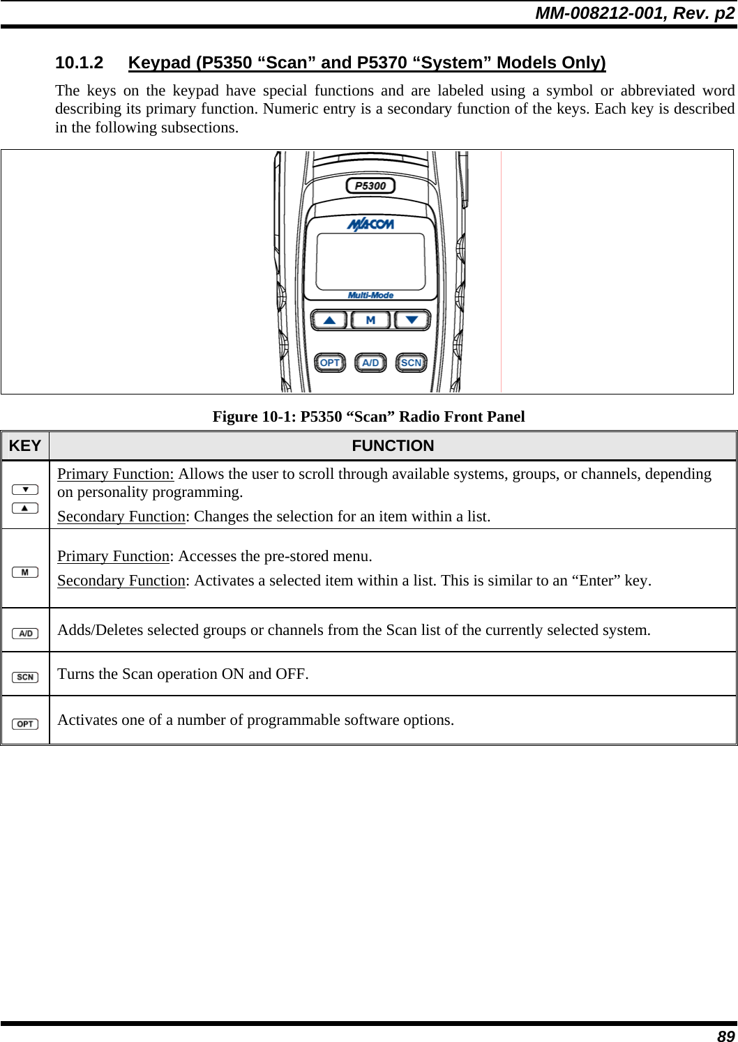
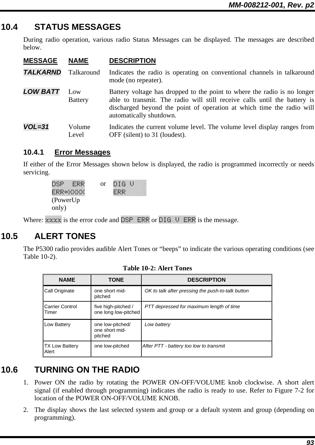
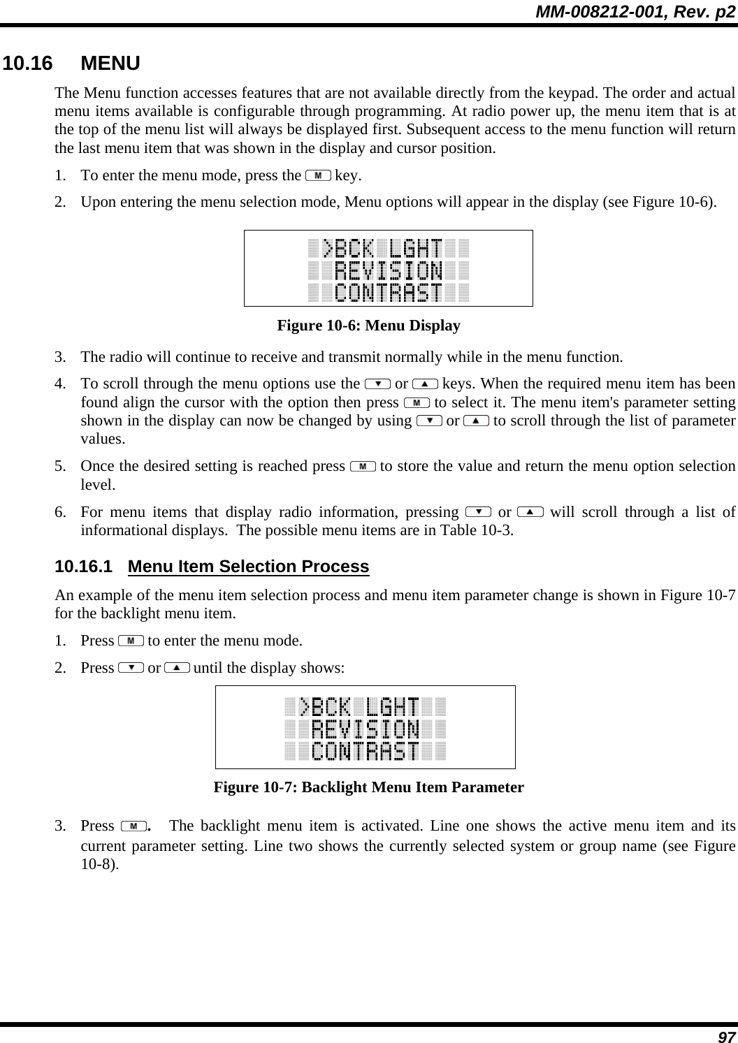
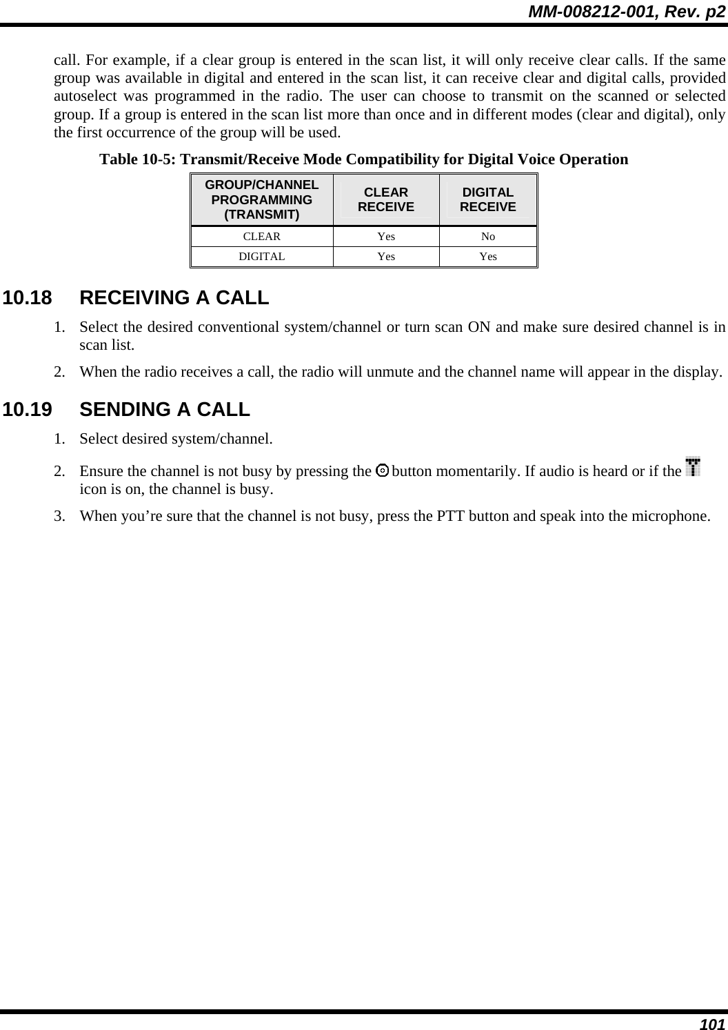
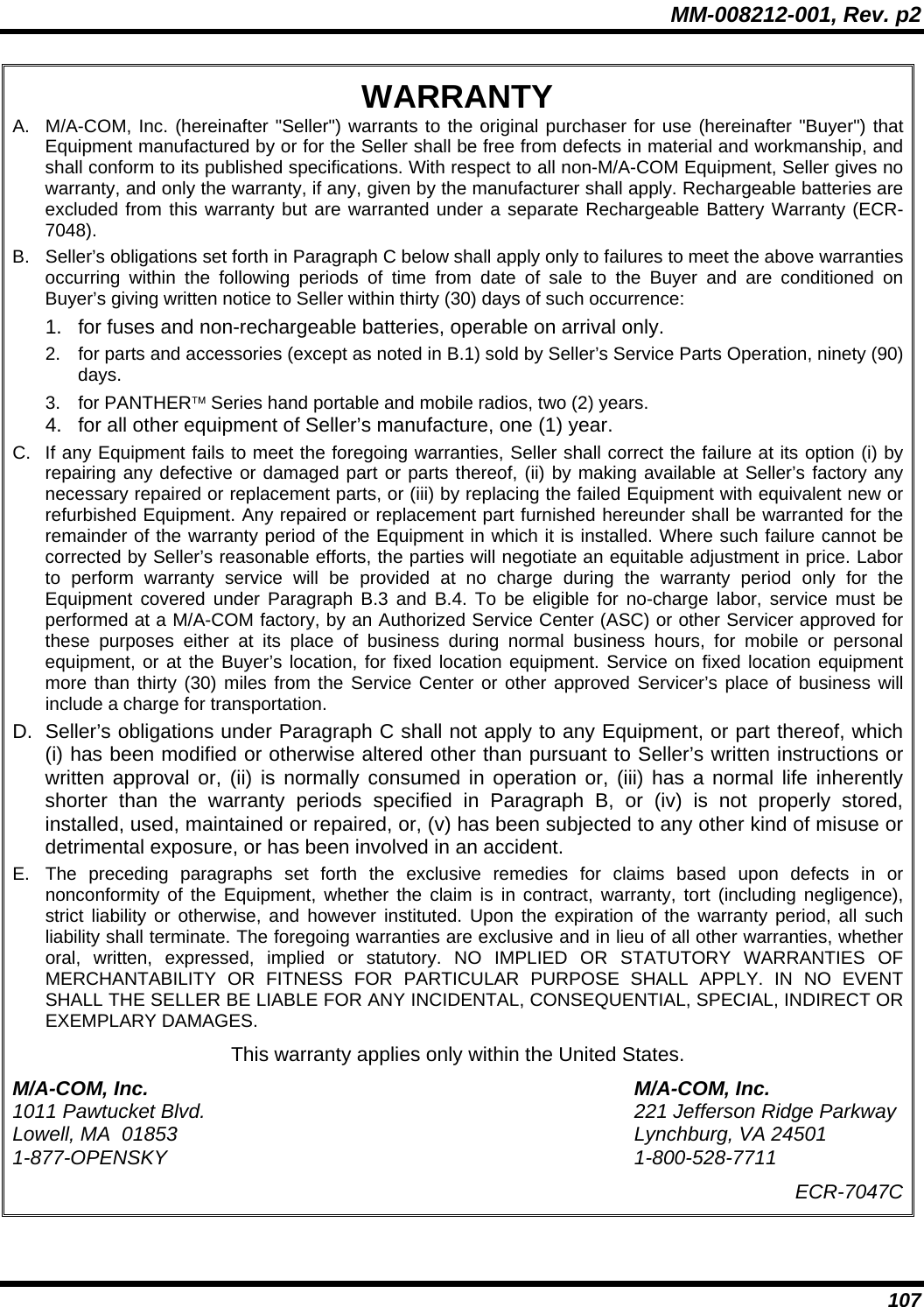
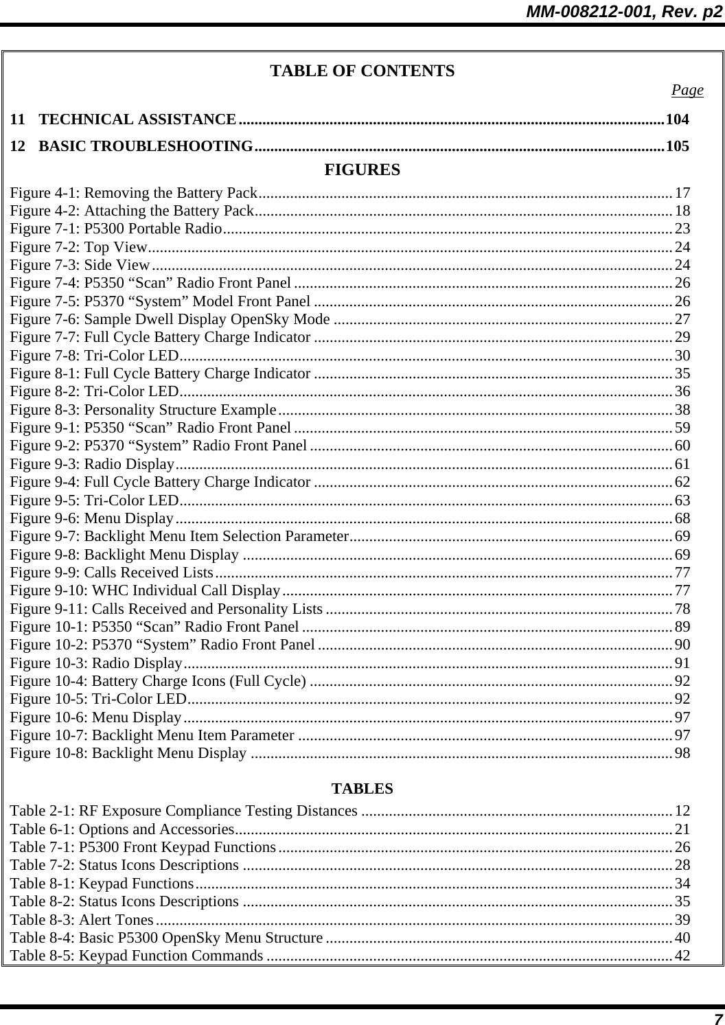
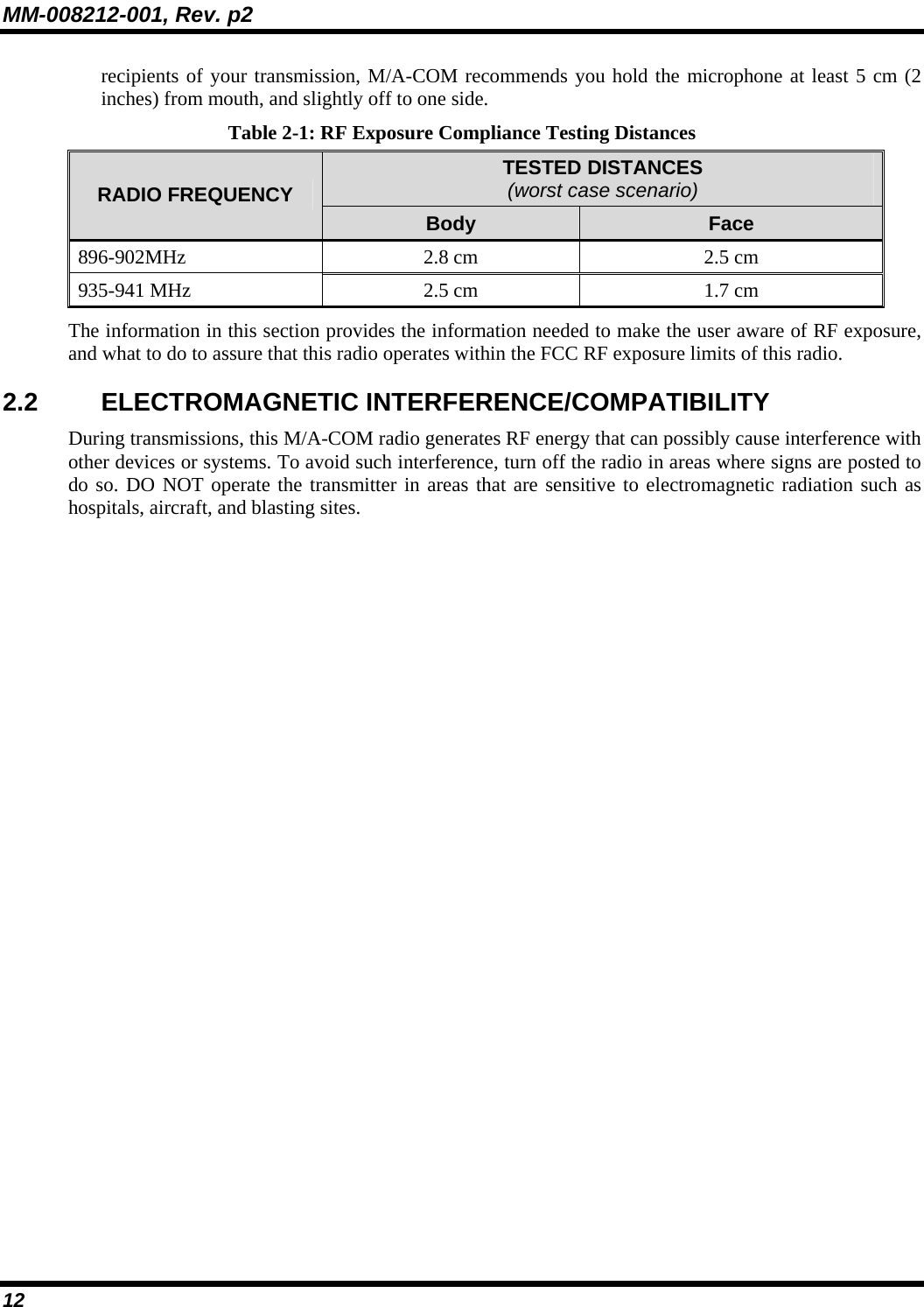
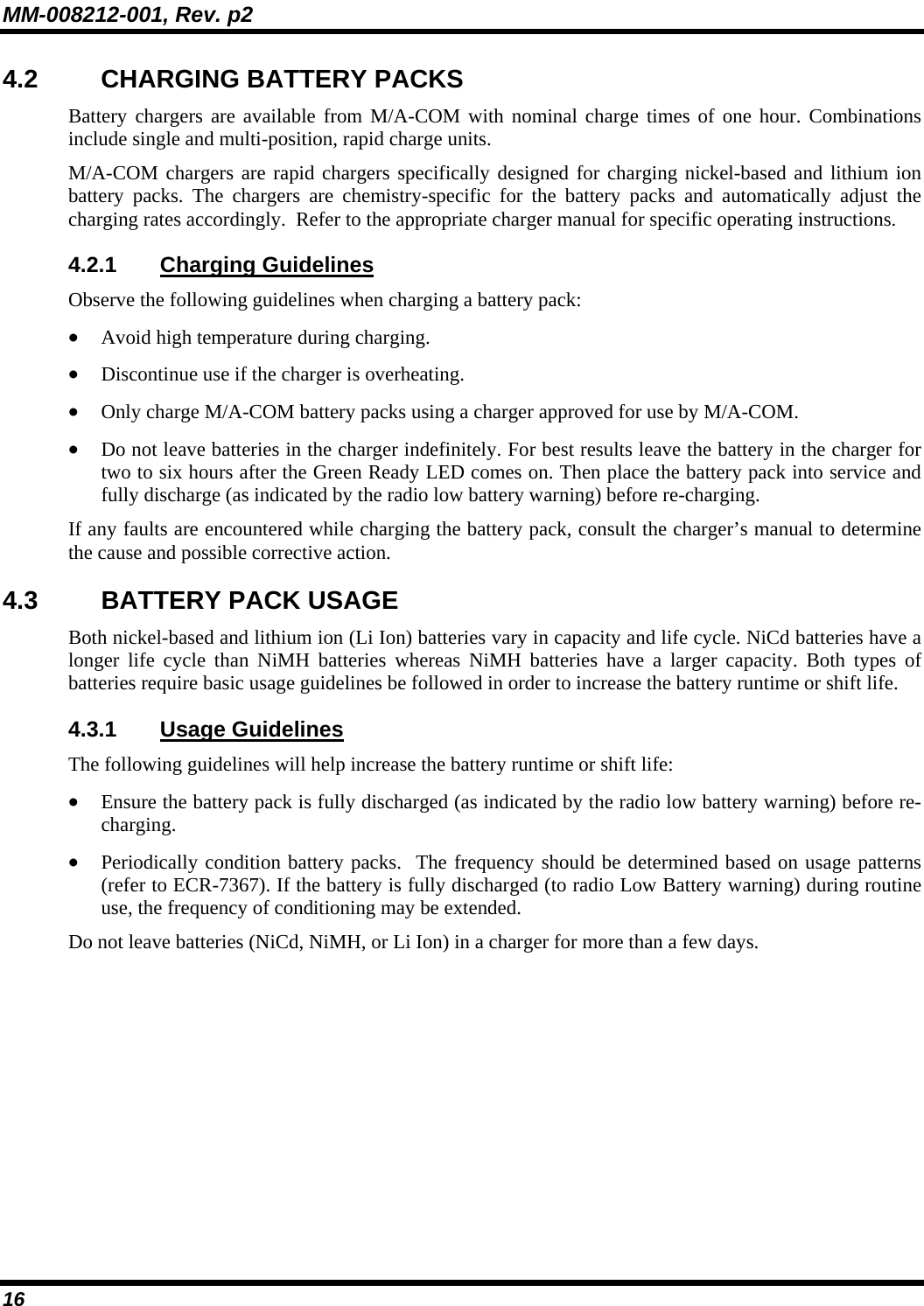
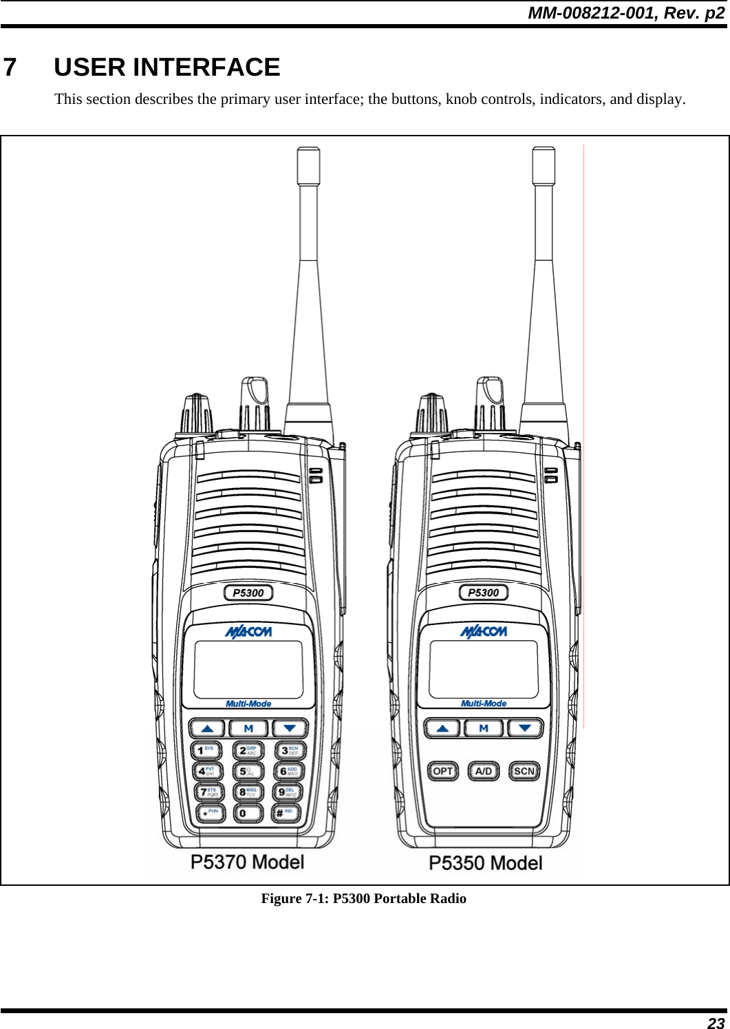
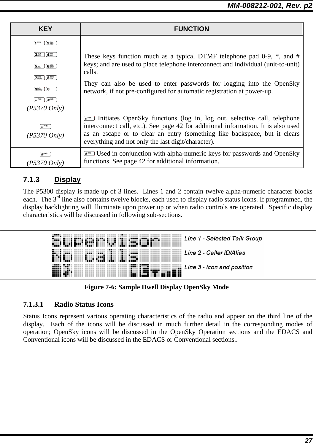
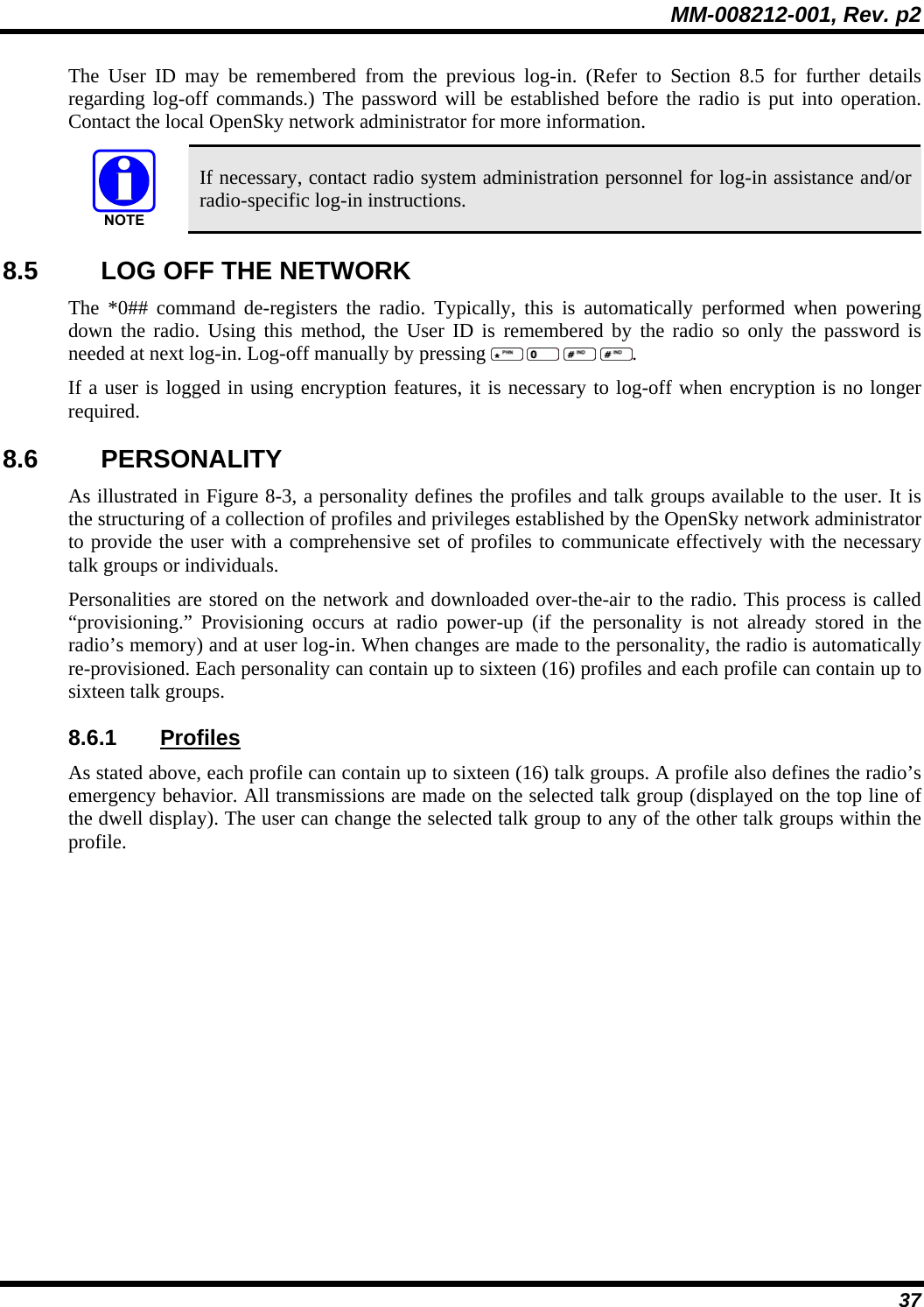
![MM-008212-001, Rev. p2 55 8.27 GPS COORDINATES The radio’s current latitude and longitude coordinates may be displayed using the “GPS” menu. The following procedure assumes a GPS antenna is connected to the radio and it is receiving adequate signals from GPS satellites. 1. Press or until the “GPS” menu appears in the display. Current GPS coordinate latitude and longitude data continuously scrolls in the top line of the display in a degrees:minutes:seconds format. 2. Press or to change to another menu. If the internal GPS receiver’s data is expired (30 minutes or more) or unavailable, the radio uses the serving base station’s coordinates [GPS (Site) is displayed]. The GPS Menu will also indicate if the data is aged (2 minutes or more) [GPS (Aged) is displayed]](https://usermanual.wiki/HARRIS/TR-0047-E/User-Guide-794529-Page-56.png)