HARRIS TR-0060-E M7300/M5300 Mobile Radio User Manual MM 014716 001 Rev F M7300 Series Mobile Radios
HARRIS CORPORATION M7300/M5300 Mobile Radio MM 014716 001 Rev F M7300 Series Mobile Radios
HARRIS >
Contents
- 1. Manual 1
- 2. Manual 2
- 3. manual 2
- 4. Manual 3
Manual 3


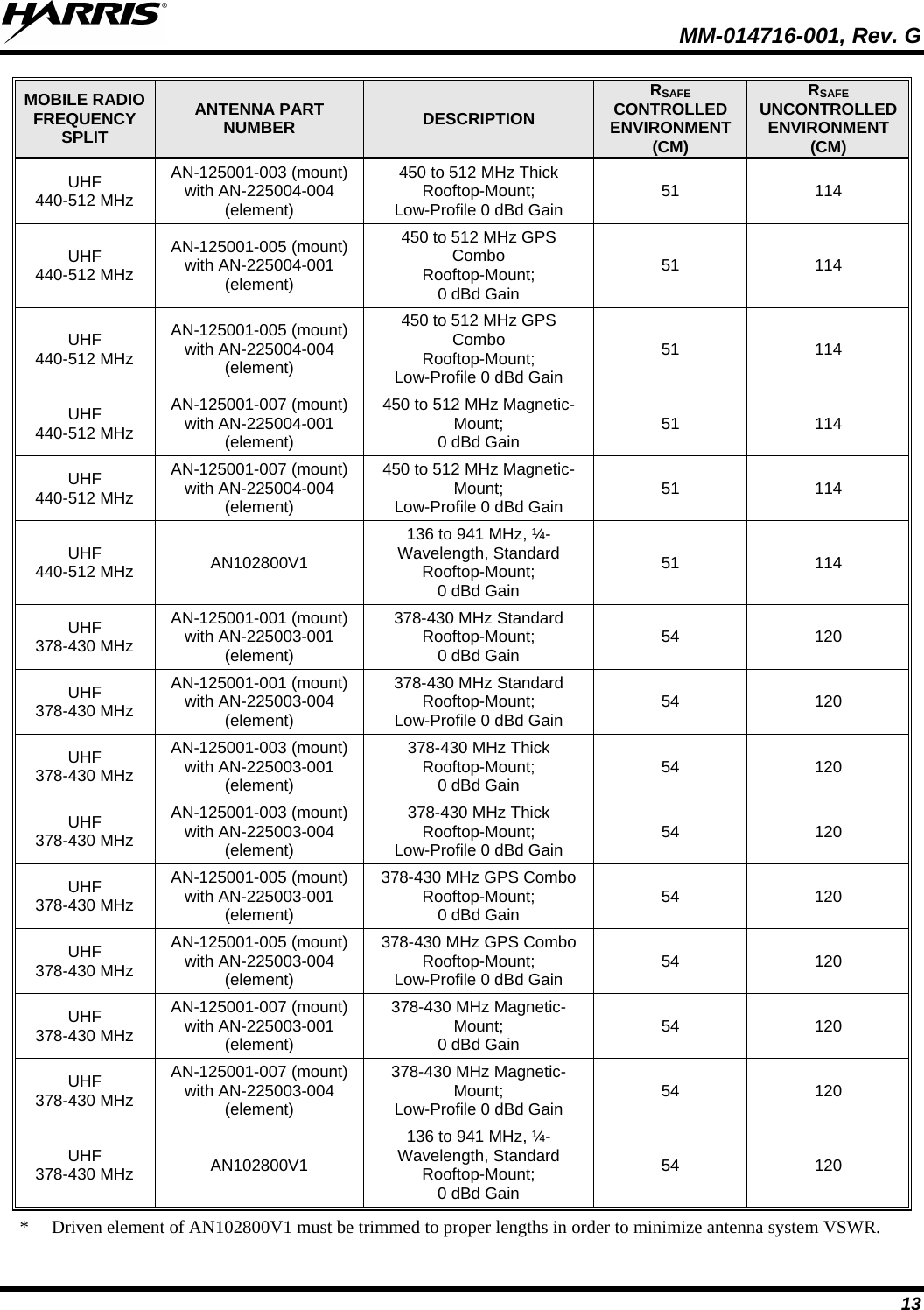
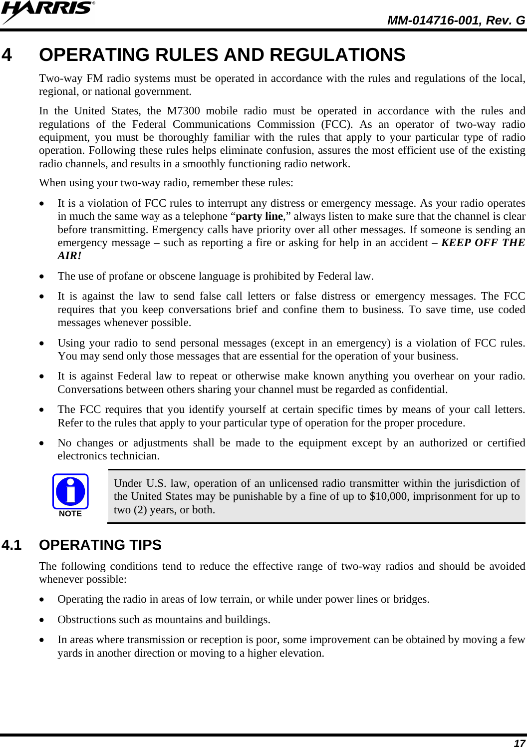
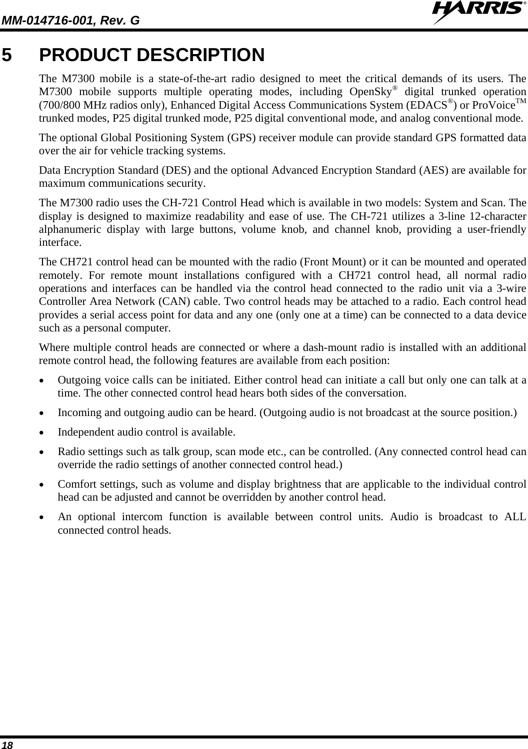
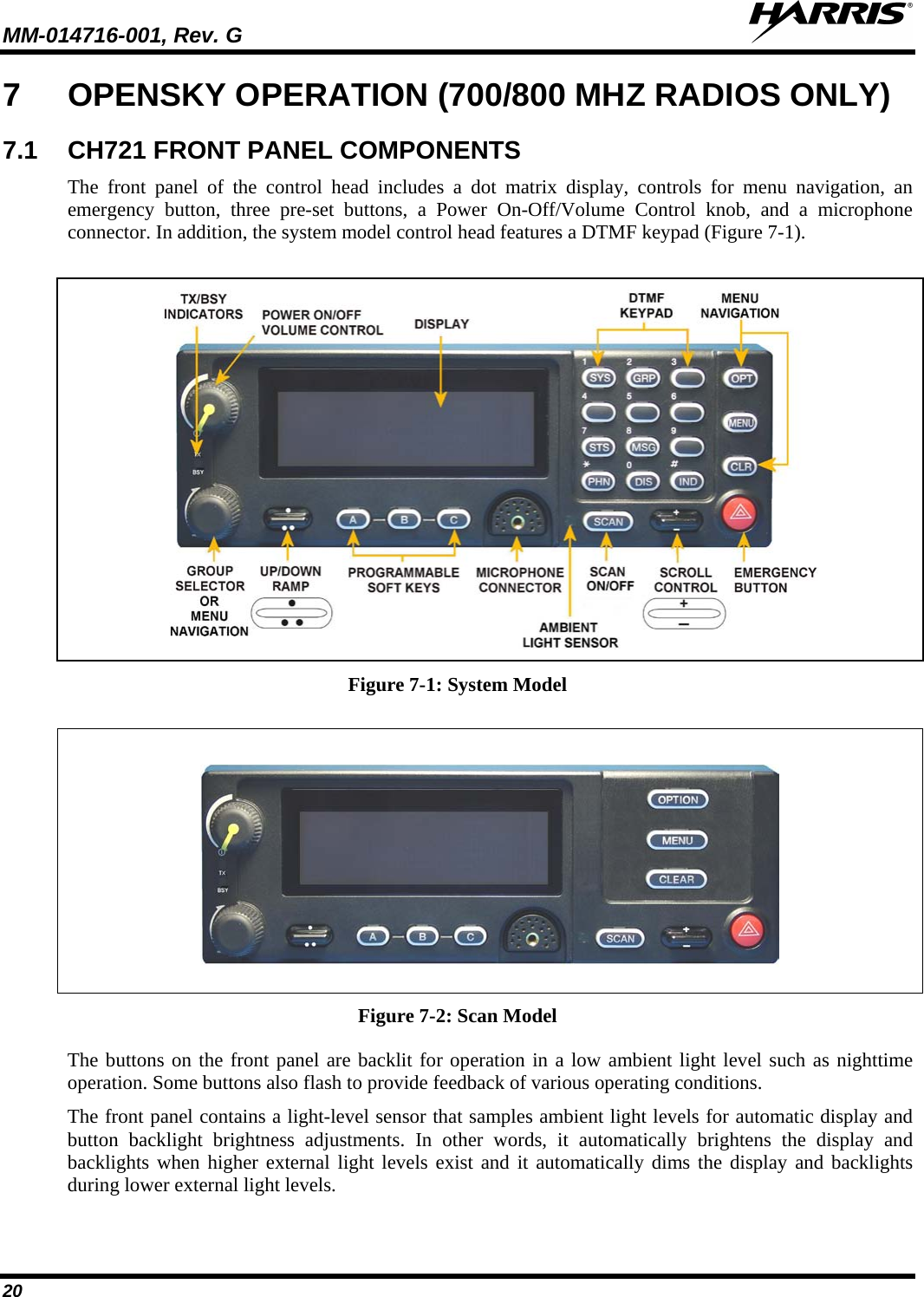
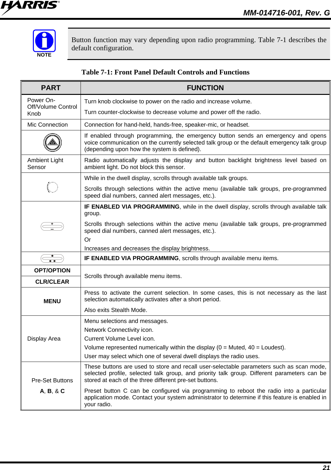
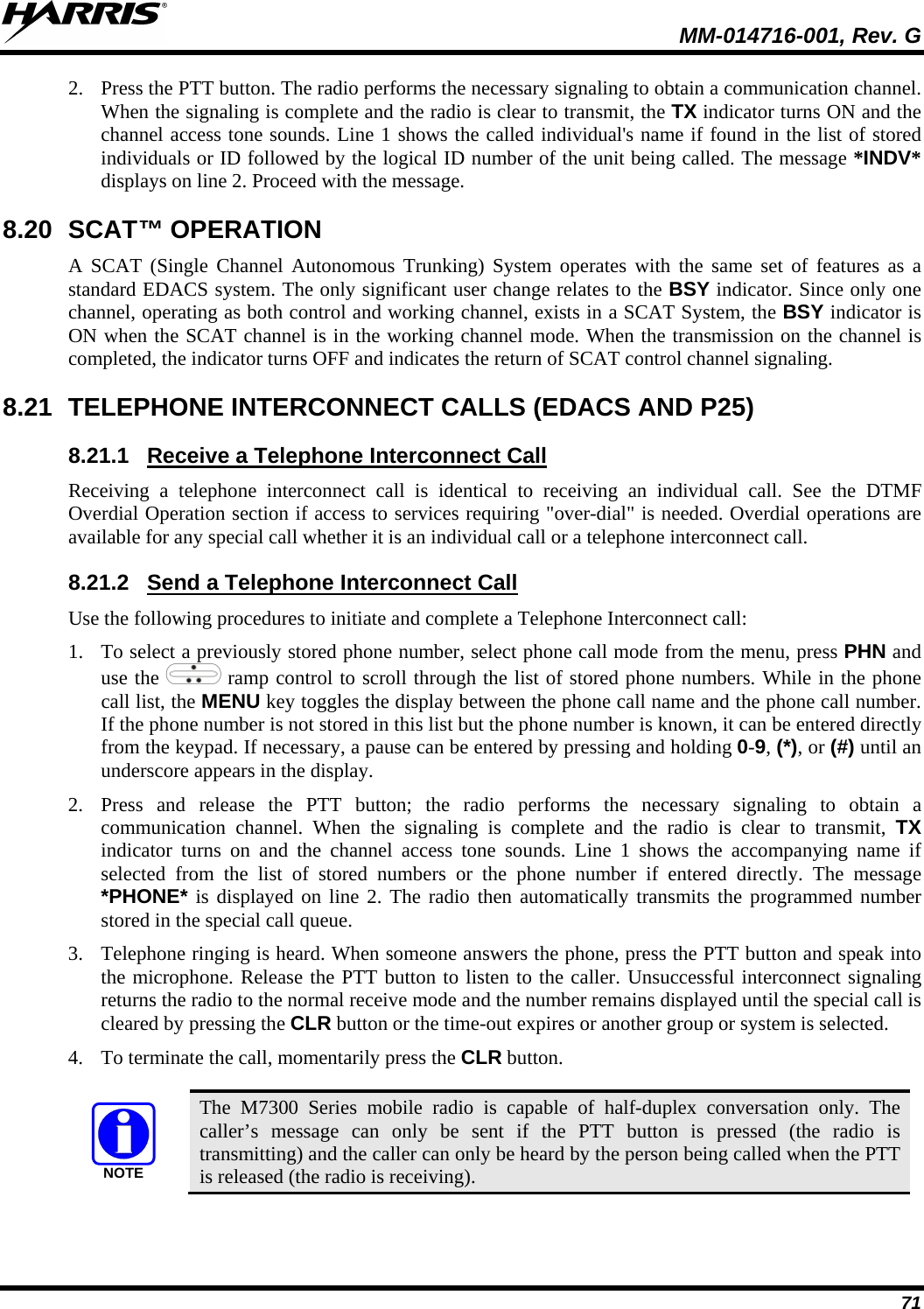
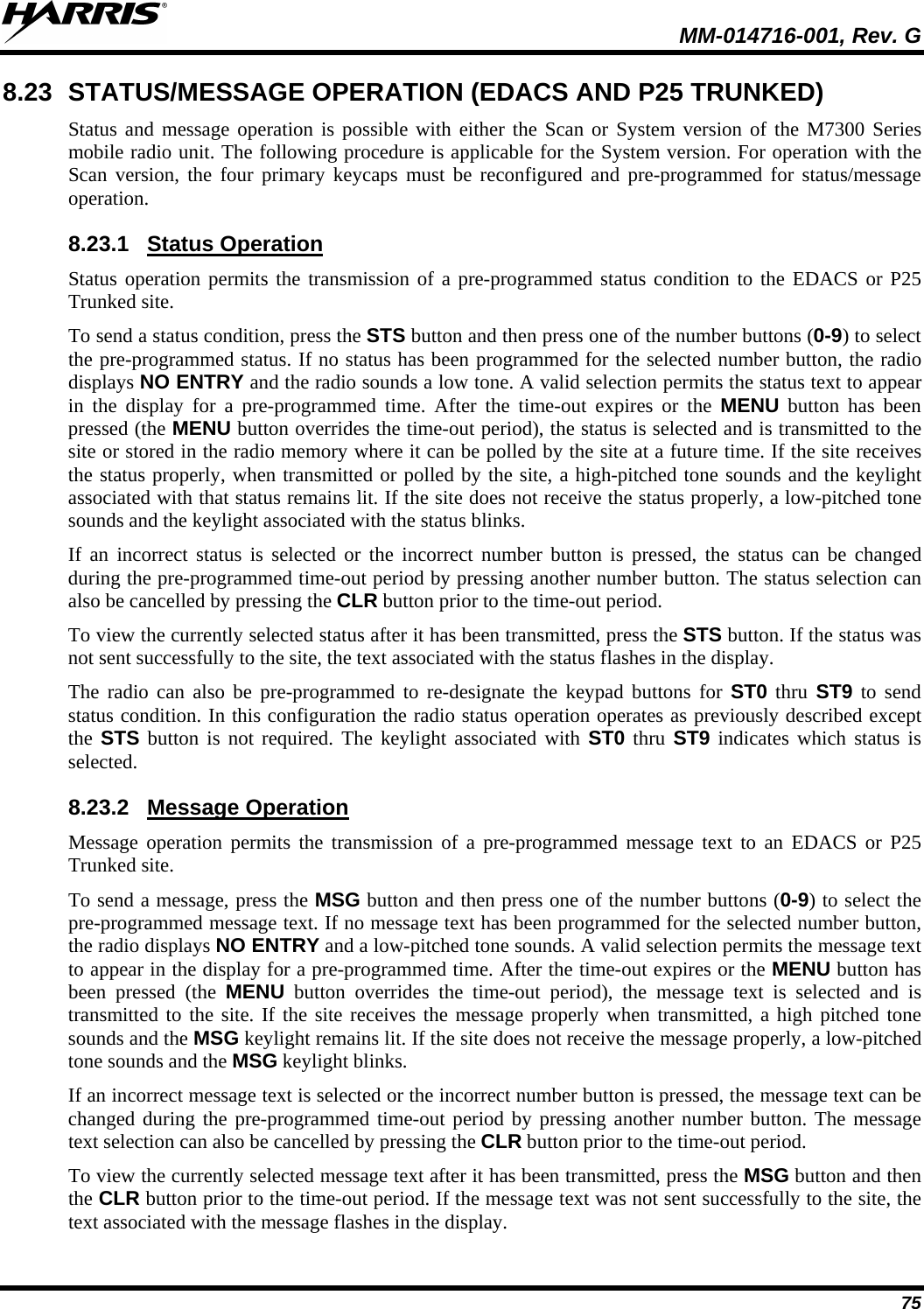
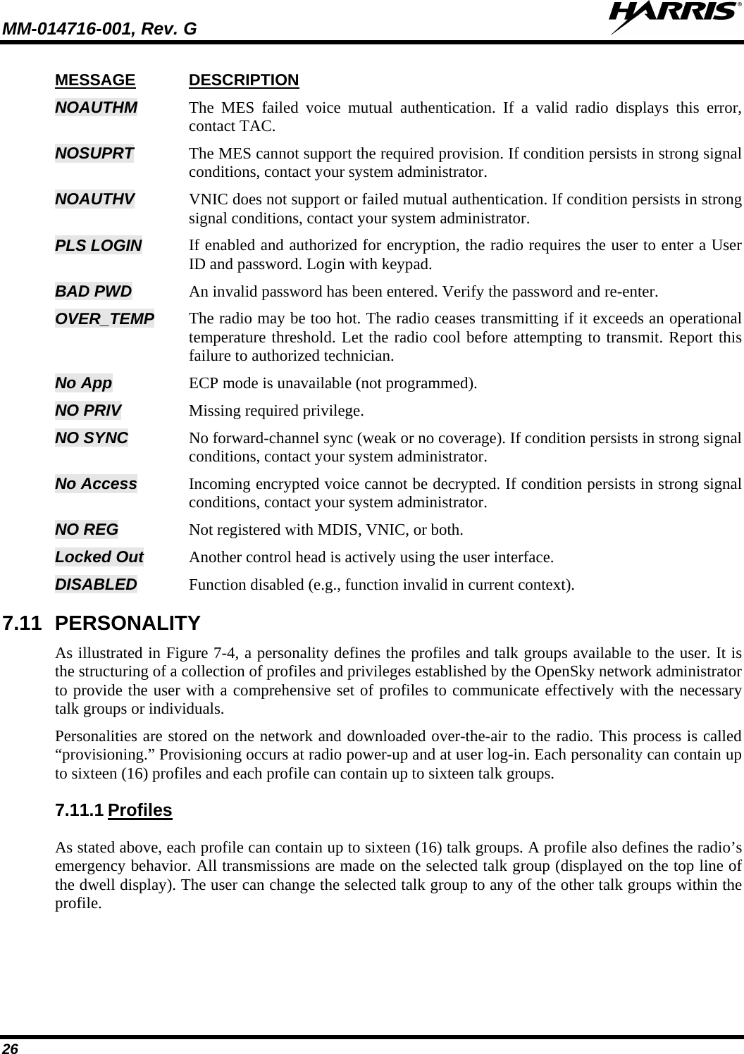
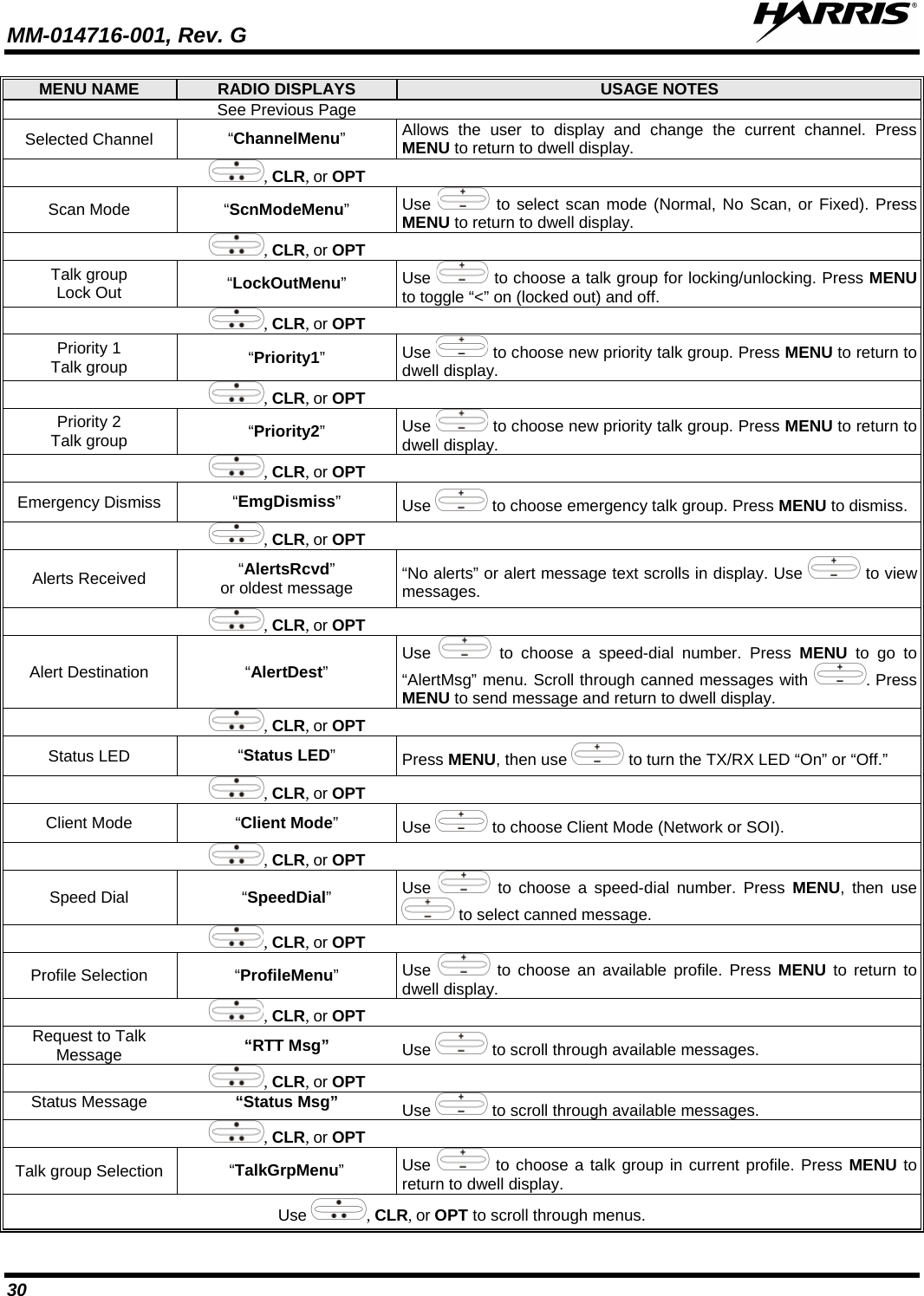
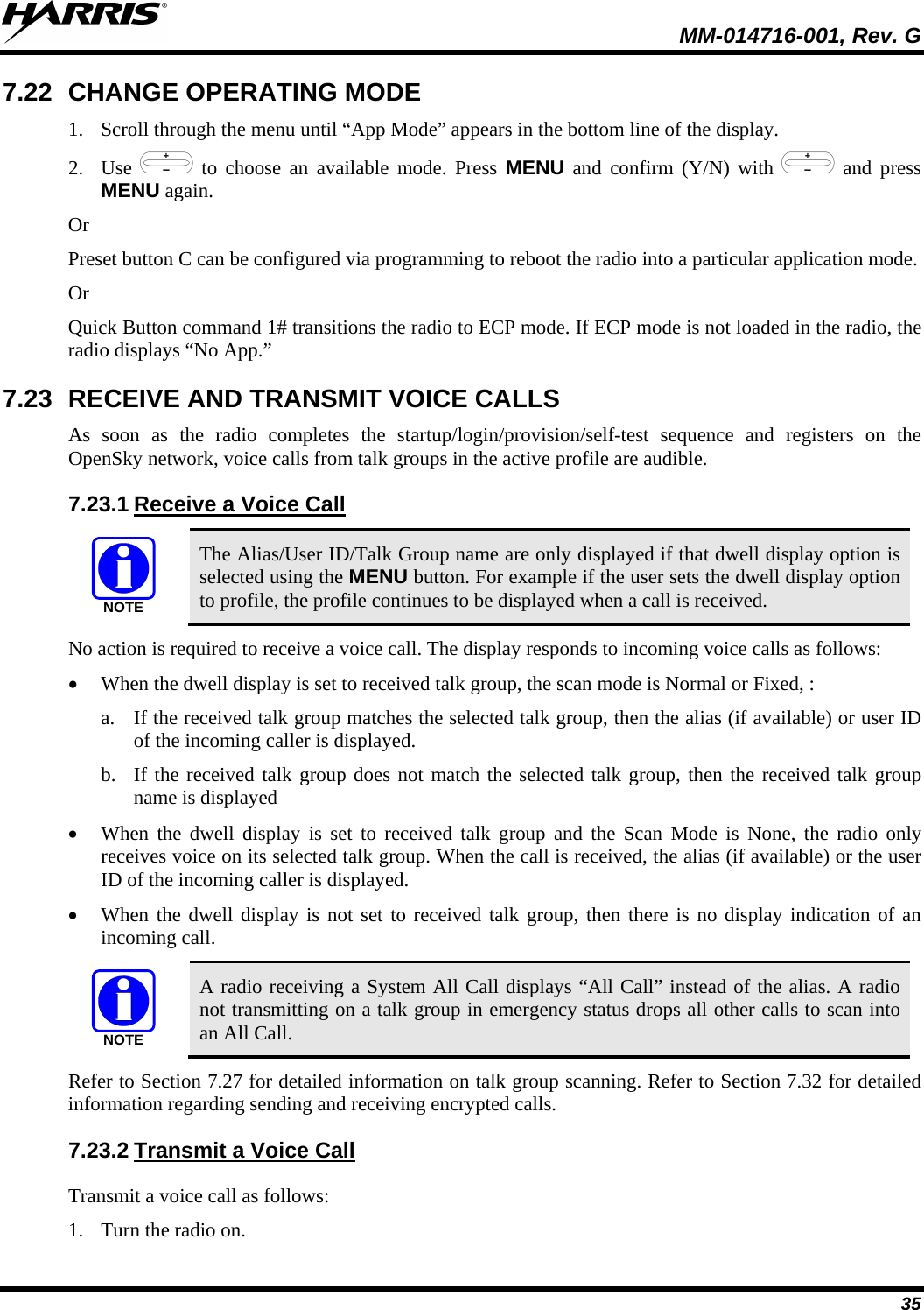
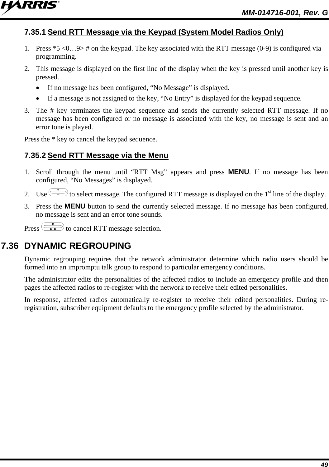
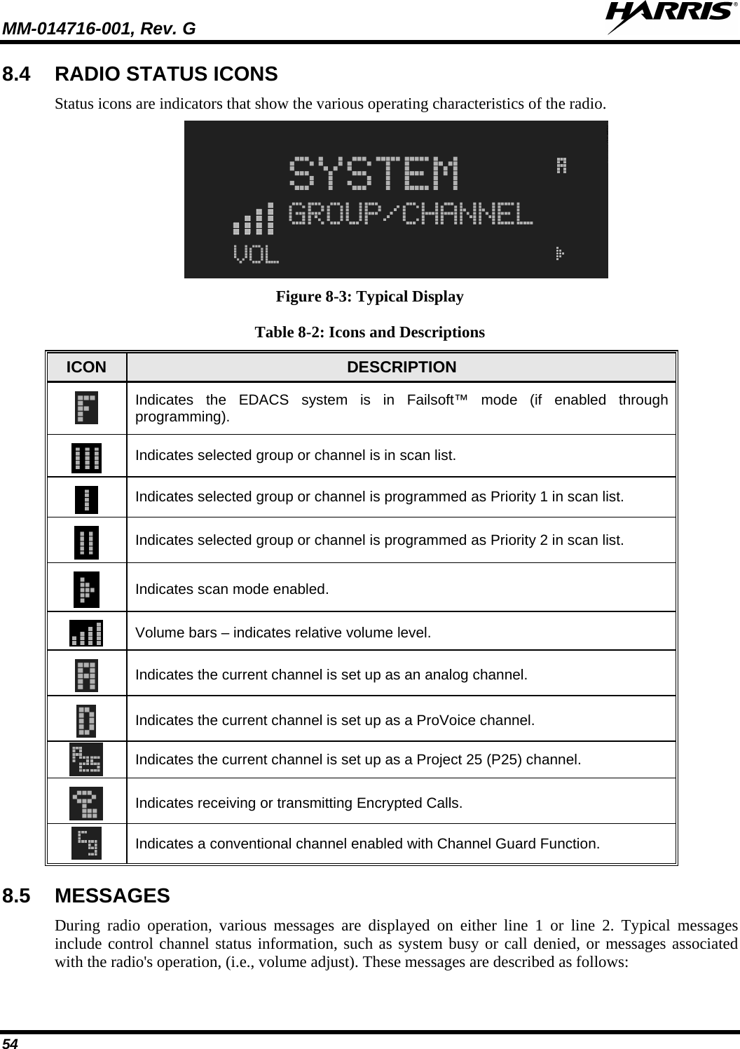
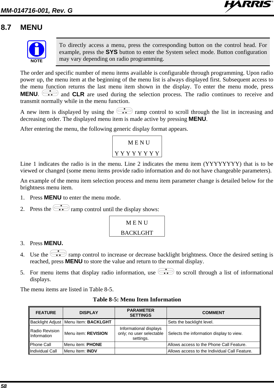
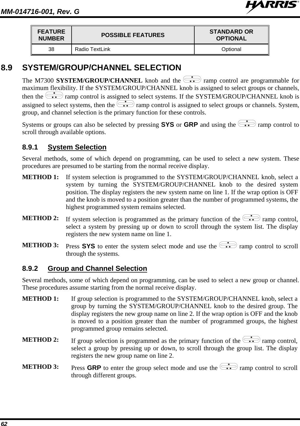
![MM-014716-001, Rev. G 22 PART FUNCTION SCAN Toggles the Scan Mode ON/OFF. • If the Scan Mode is Normal and the Scan Mode is toggled Off, when the Scan Mode is toggled On the Scan Mode is set to Normal. • If the Scan Mode is Fixed and the Scan Mode is toggled Off when the Scan Mode is toggled On the Scan Mode is set to Fixed . • If the Scan Mode is Off when the radio boots up when the Scan Mode is toggled On the Scan Mode is set to Normal. 7.2 POWER UP AND VOLUME CONTROL 7.2.1 1. Rotate the Power On-Off/Volume Control knob clockwise to power on the radio. The display illuminates when the radio powers up. Power Up 2. Wait for the power-up sequence to complete, which takes approximately ten (10) seconds. During this time, if enabled for auto registration, the radio is provisioned with a customized user personality designed for the user’s specific needs by the OpenSky network administrator. If this personality contains encrypted talk groups or if the user is authorized for, and intends to use, manual encryption, User Login must be performed. This requires a system model control head so that the User ID and password can be entered. 3. When provisioning is complete, the radio displays the Dwell Display. If User Login is required, the bottom line of the Dwell Display flashes the message “Pls Login.” 7.2.2 Turn the Power On-Off/Volume Control knob clockwise to increase the volume and counter-clockwise to decrease the volume. The radio sounds a tone to indicate the current volume level. Volume Control 7.3 SELF-TEST After power-up, the M7300 radio undergoes a multi-function automatic registration procedure. As many as sixteen (16) possible radio profiles are downloaded to the radio from the network in response to the User’s ID. 7.4 LOGIN TO THE NETWORK Login occurs either automatically (auto registration) if the radio has a valid registration or, if enabled and authorized for encryption (Section 7.32), requires the user to enter a User ID and password. If encryption is enabled and authorized on the radio, the user is prompted to “Pls Login” with the *1 login command, a User ID, and password [System Model Control Head required]. 1. Press *1 (Login command). 2. Enter the full 10-digit User ID. 3. Press the # key.](https://usermanual.wiki/HARRIS/TR-0060-E.Manual-3/User-Guide-1507435-Page-22.png)
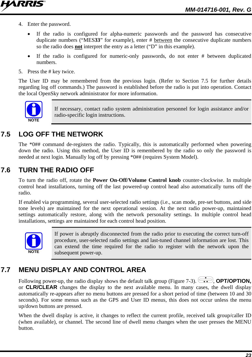
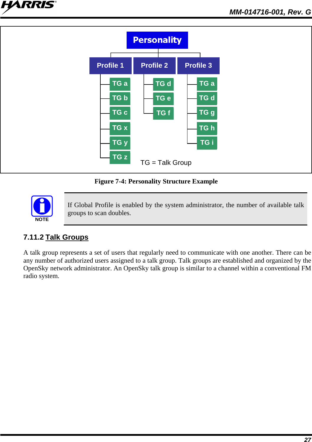
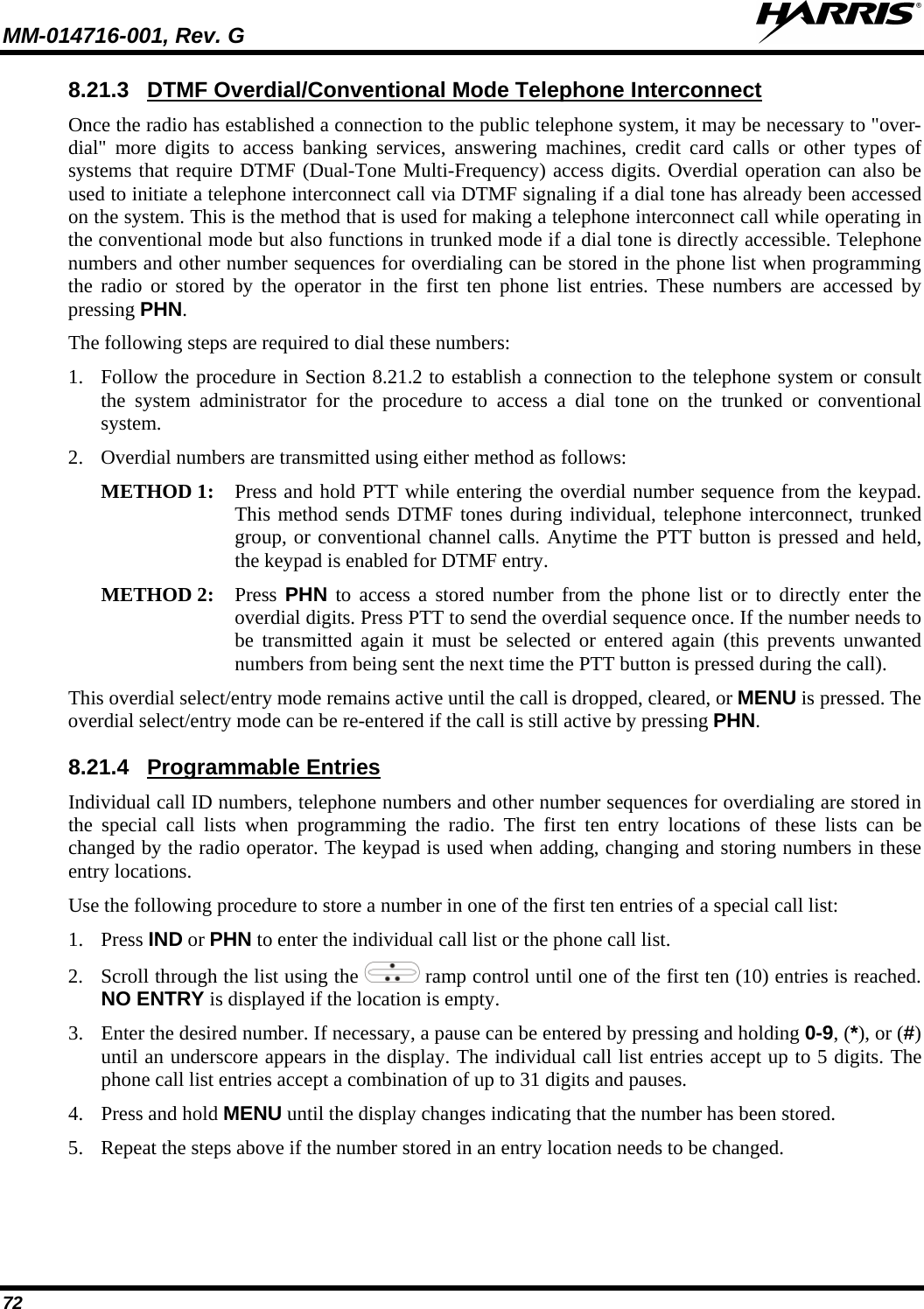
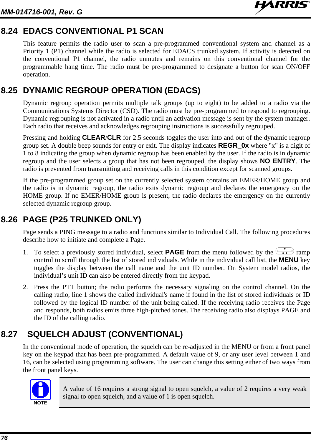
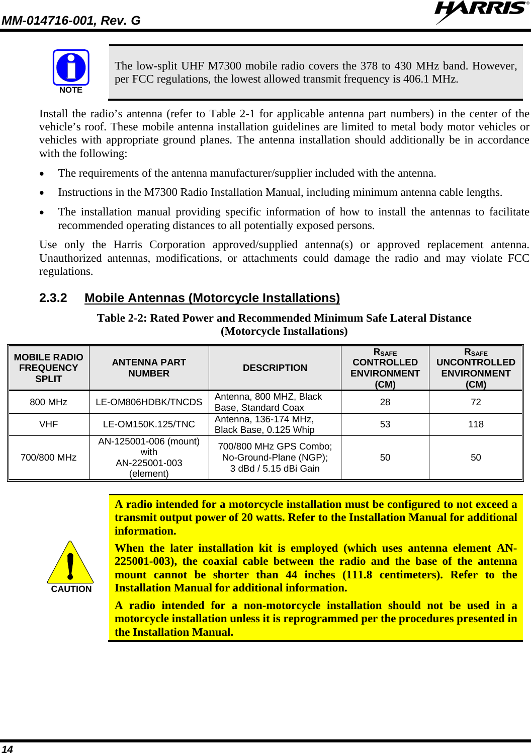
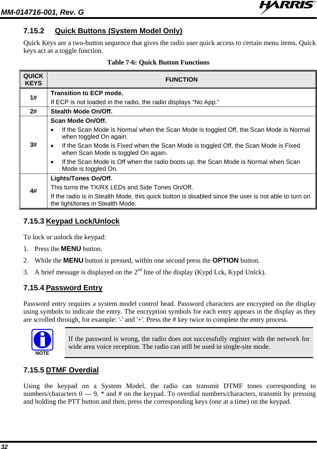
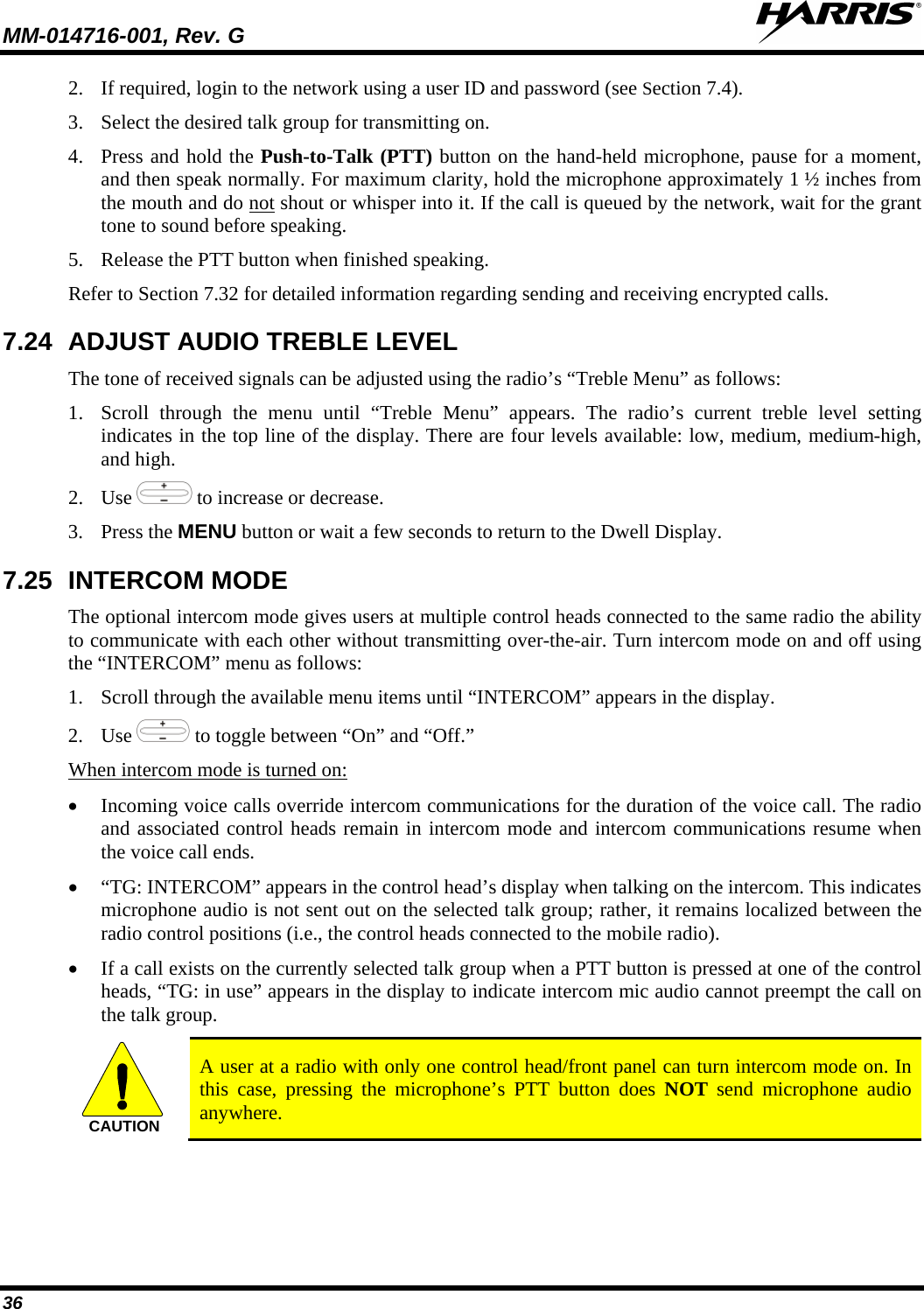
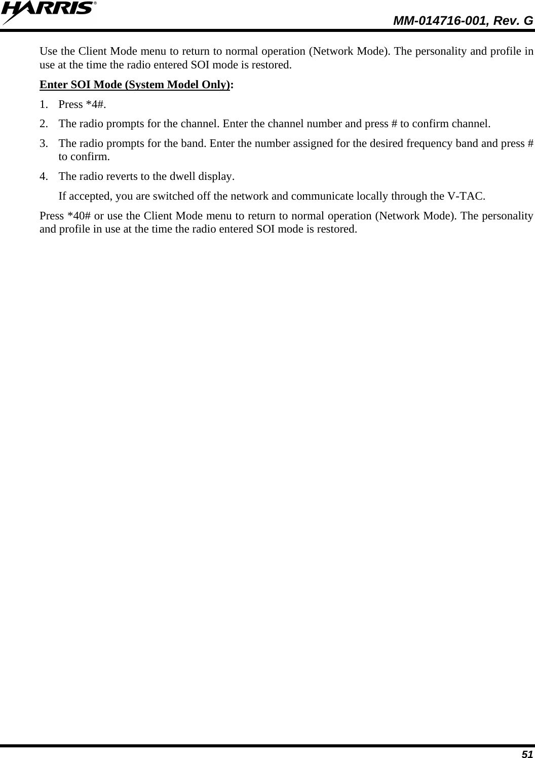
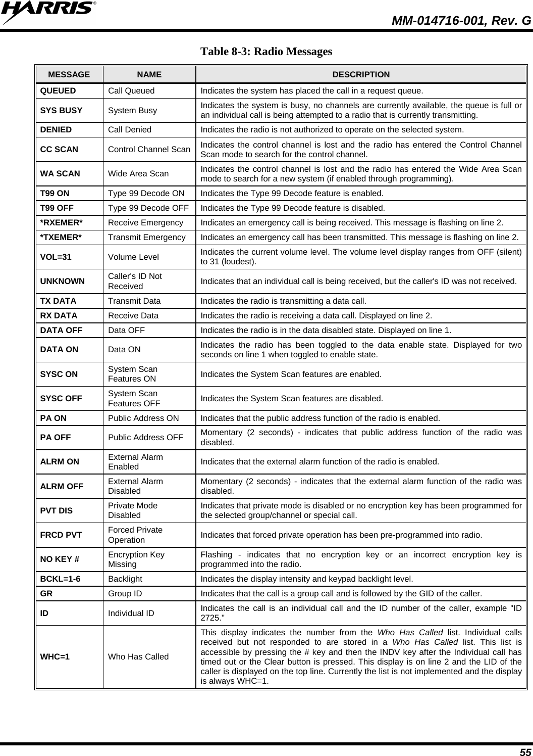
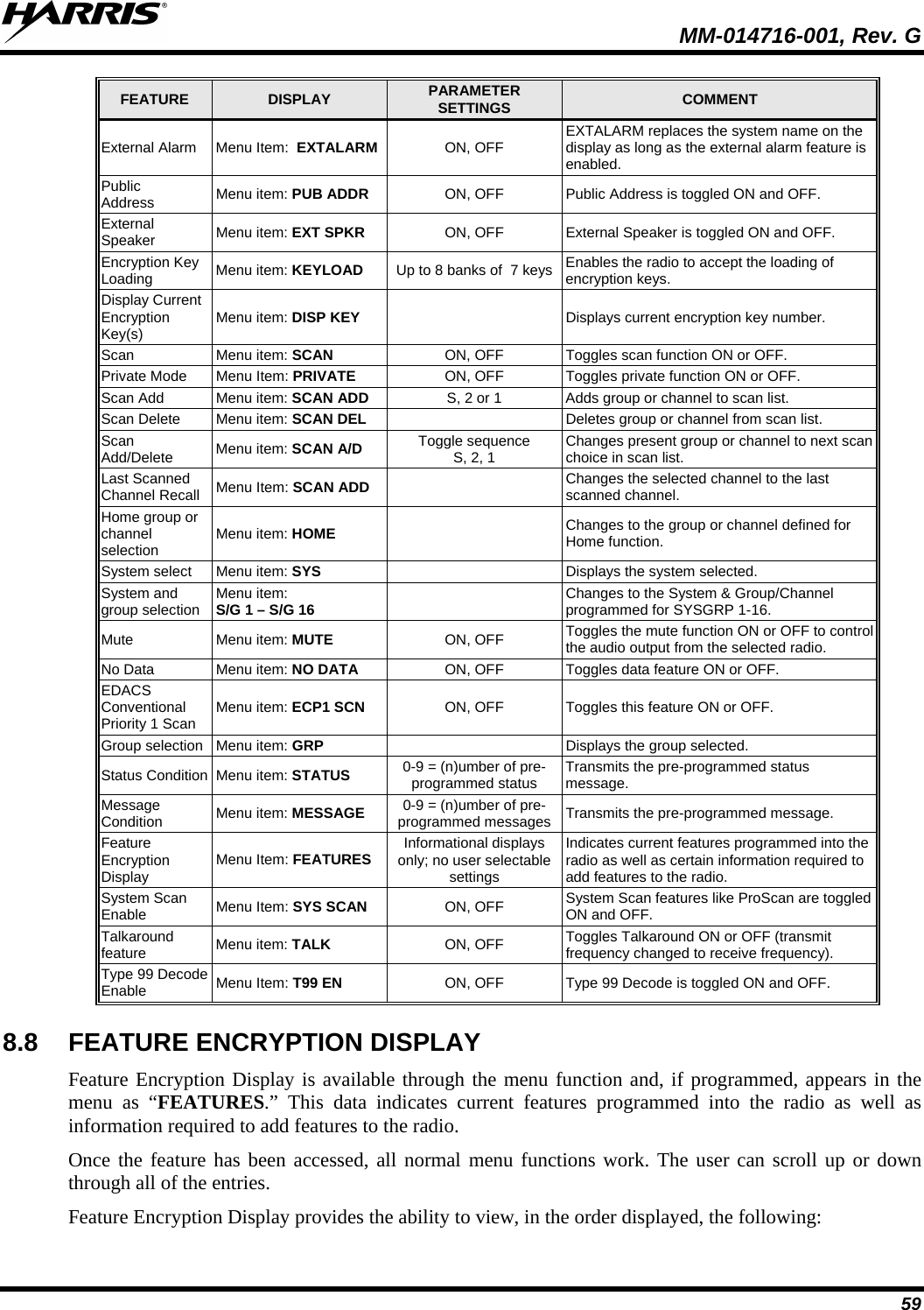
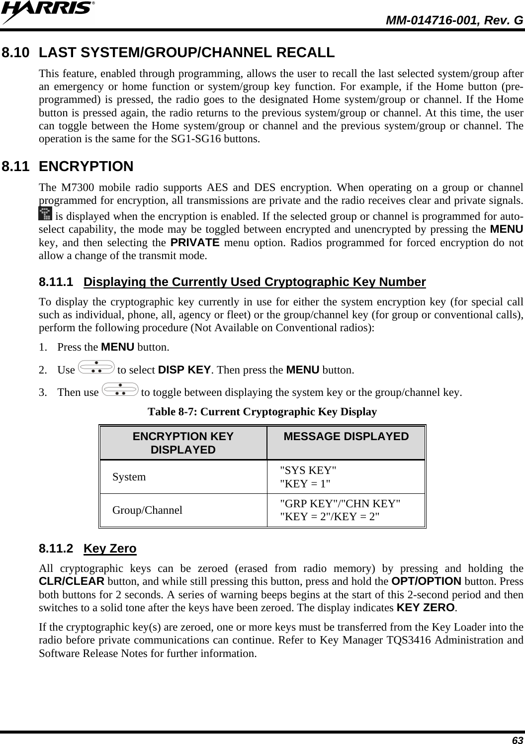
![MM-014716-001, Rev. G 31 NOTE Menus vary depending upon system programming, radio hardware, and optional configurations. 7.14 DUAL-TONE MULTI-FREQUENCY Dual-Tone Multi-Frequency (DTMF) is the system used by touch-tone telephones. DTMF assigns a specific tone frequency to each key so a microprocessor can easily identify its activation. The radio supports DTMF with a system model control head (Figure 7-1). This allows for specific tasks such as entering a user ID and password, or Selective Calling. When a key on the DTMF keypad is pressed, the DTMF tone is played through the radio’s speaker. 7.15 KEYPAD 7.15.1 To perform a command from the keypad, press the * key followed by one of the pre-set function keys as follows: Keypad Commands (System Model Control Head) Table 7-5: Keypad Function Commands KEYPAD COMMAND FUNCTION *0 Log off command: *0## (logs the user off the system). See page 23 for additional information. *1 Login command: *1<User ID> # <Password> # (required for encryption). See page 22 for additional information. *2 Status Message: *2 <0...9> #. *4 Enter Scene of Incident Mode (SOI) on specified channel and band: *4#<ccc>#<bb># where ccc is the SOI channel number and bb is the number assigned to each frequency band. Press *40# to exit SOI mode. *5 RTT Message: *5 <0...9> #. *7 Initiate Selective Alert command: *7<Target ID>#[Choose Message]#. See page 41 for additional information. *8 Radio-to-Radio Call command: *8<Selective call number># (PTT to dial). *9 Public Switched Telephone Network (PSTN) Call command: *9 <telephone number># (PTT to dial). See page 43 for additional information. *32 Begin Manual Encryption command: *32<Pre-Determined Encryption Key ># 1 – 16 digit encryption key for 128 bit encryption; 17 – 32 digit encryption key for 256 bit encryption. See page 46 for additional information. *33 End Manual Encryption command: *33#](https://usermanual.wiki/HARRIS/TR-0060-E.Manual-3/User-Guide-1507435-Page-31.png)
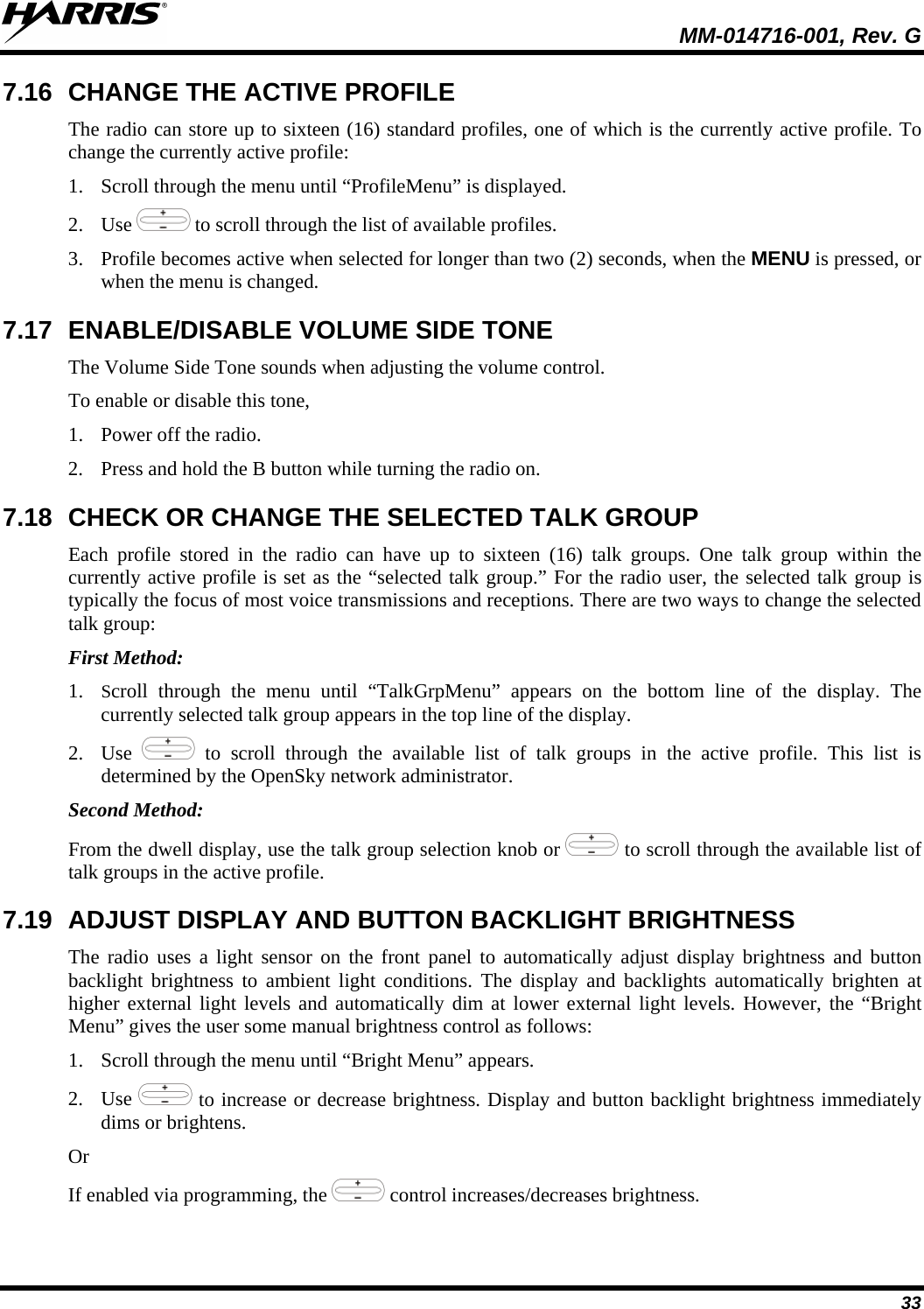
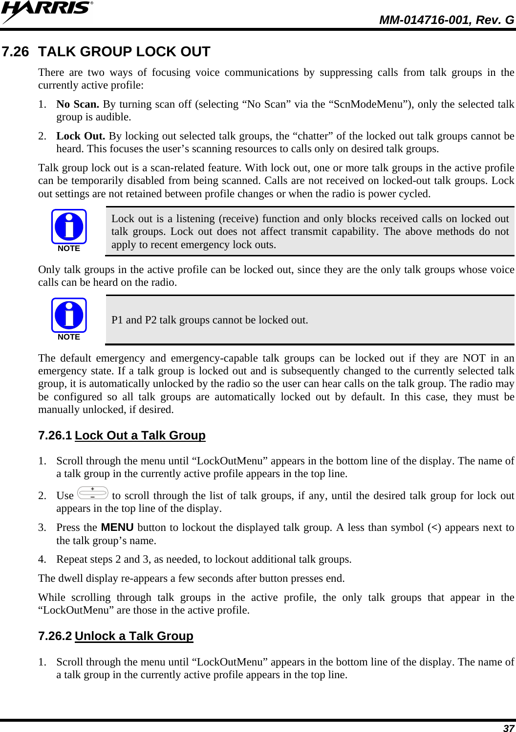

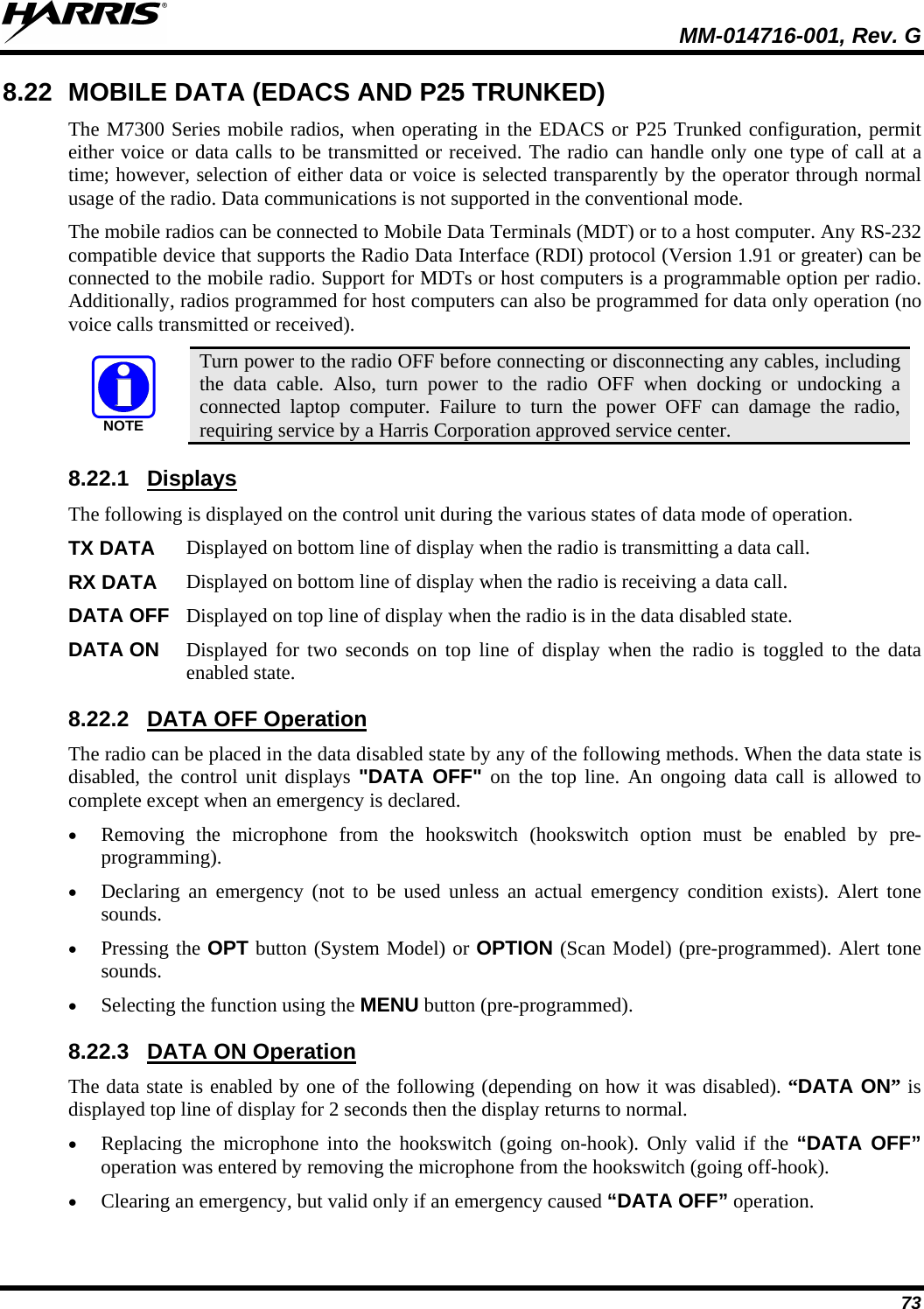
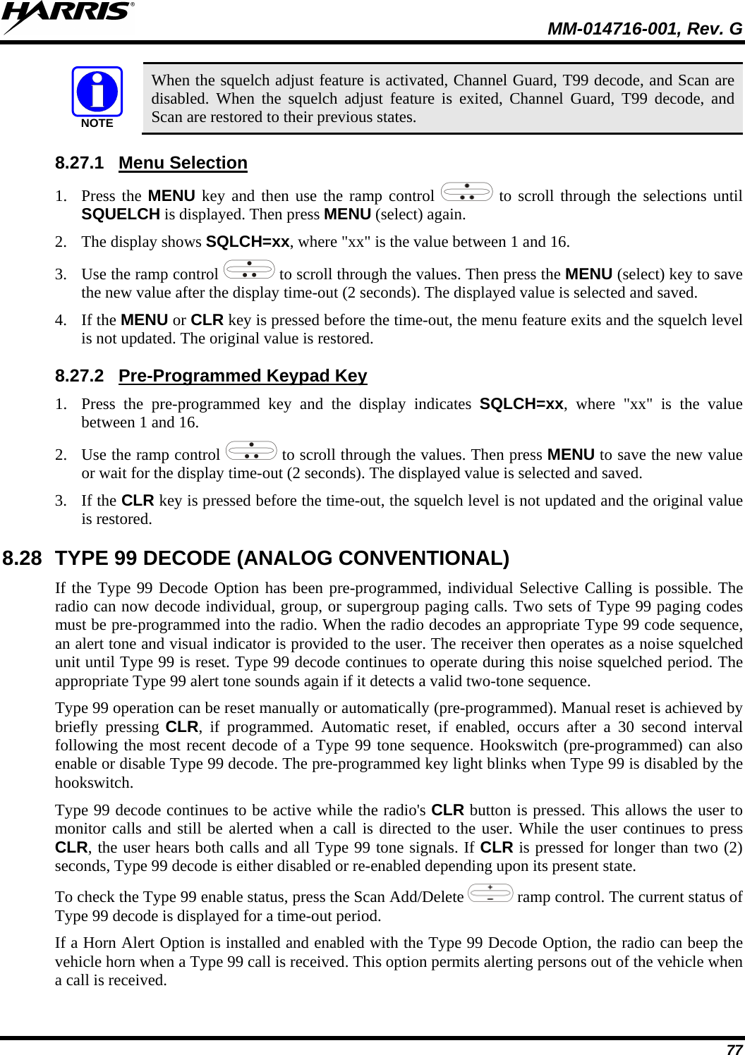
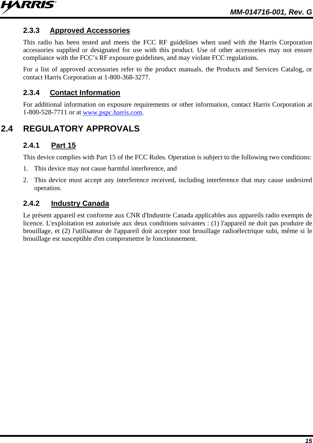
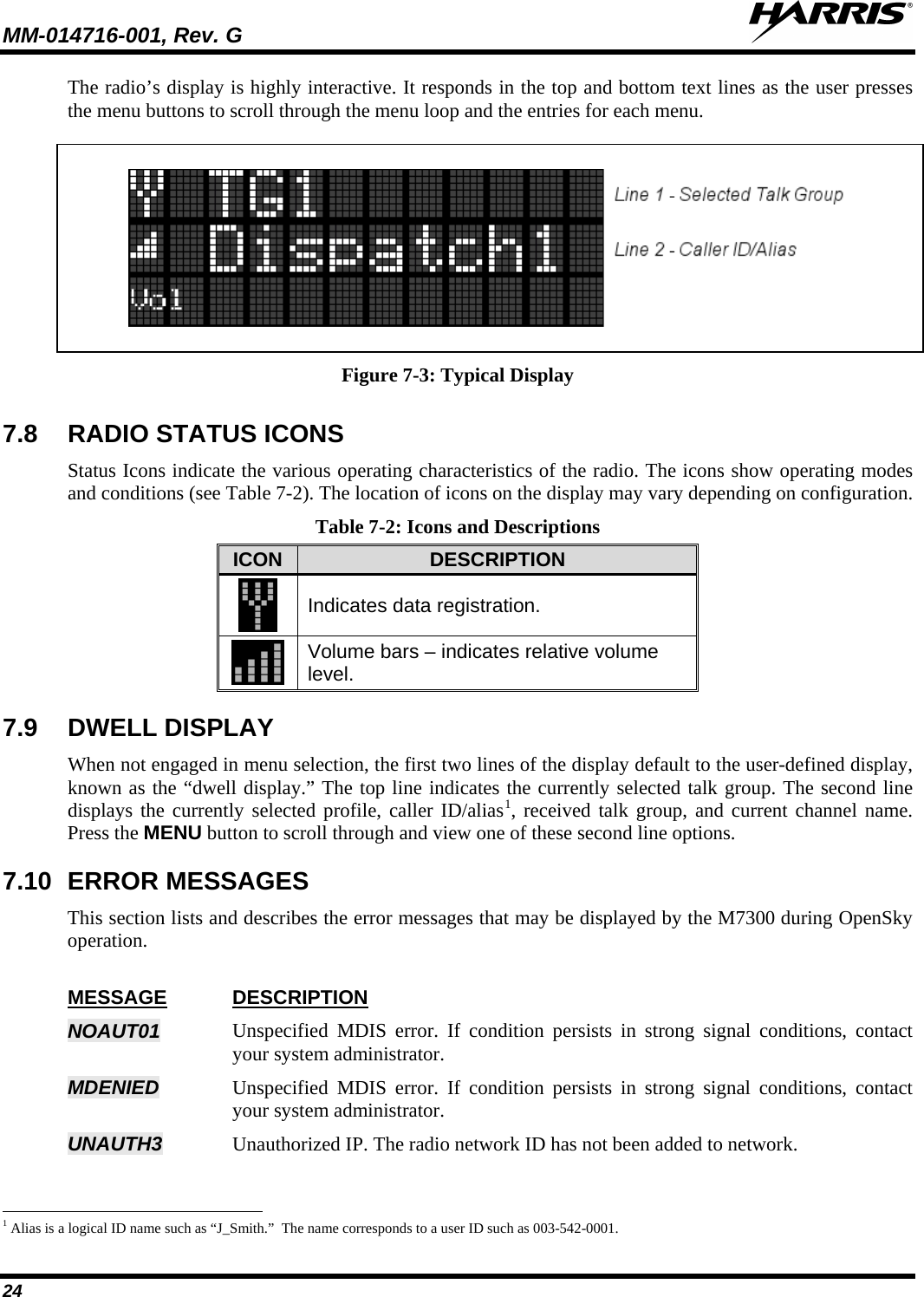
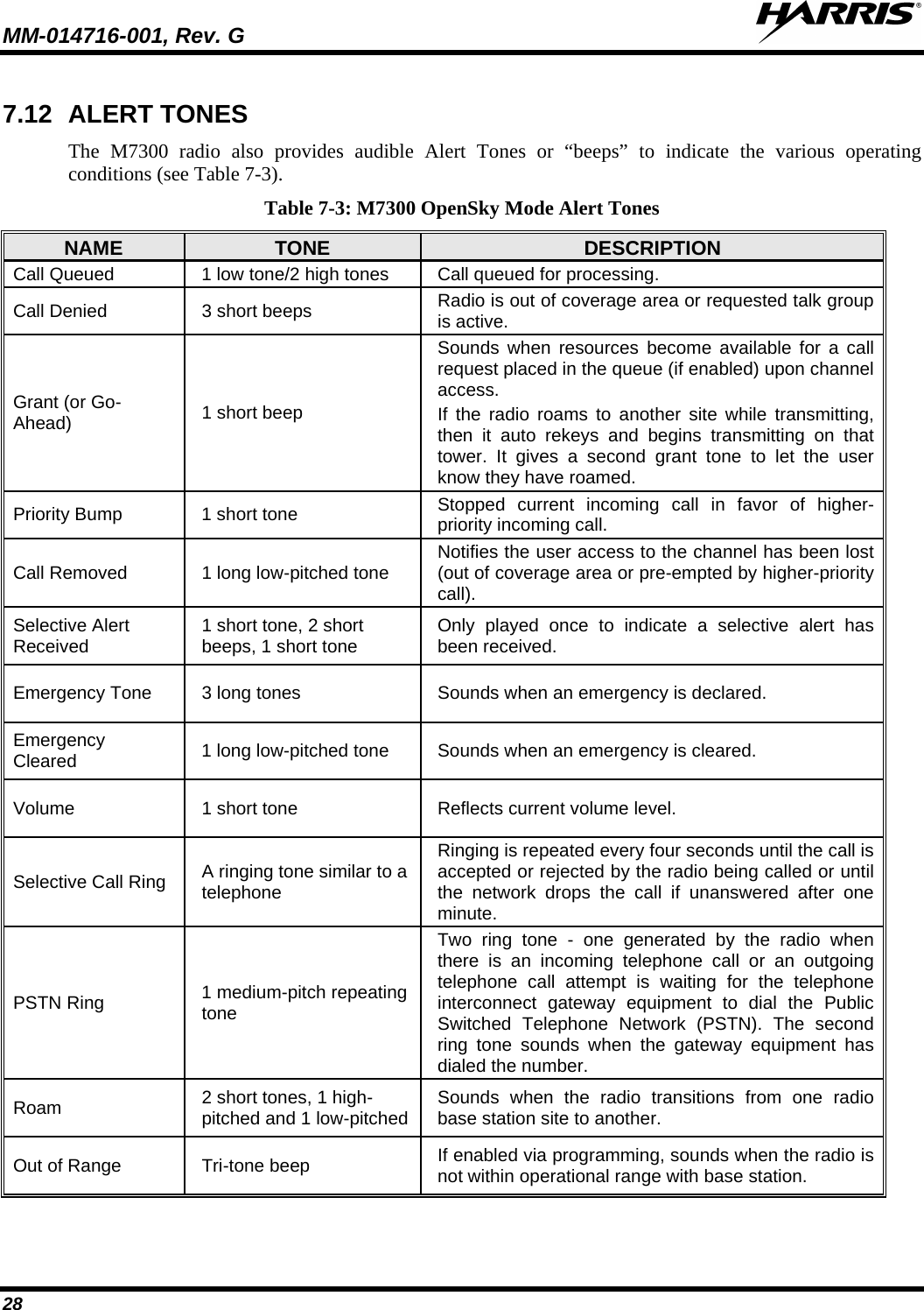
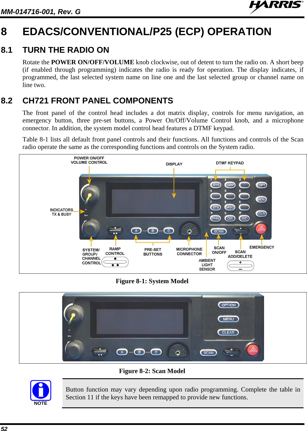
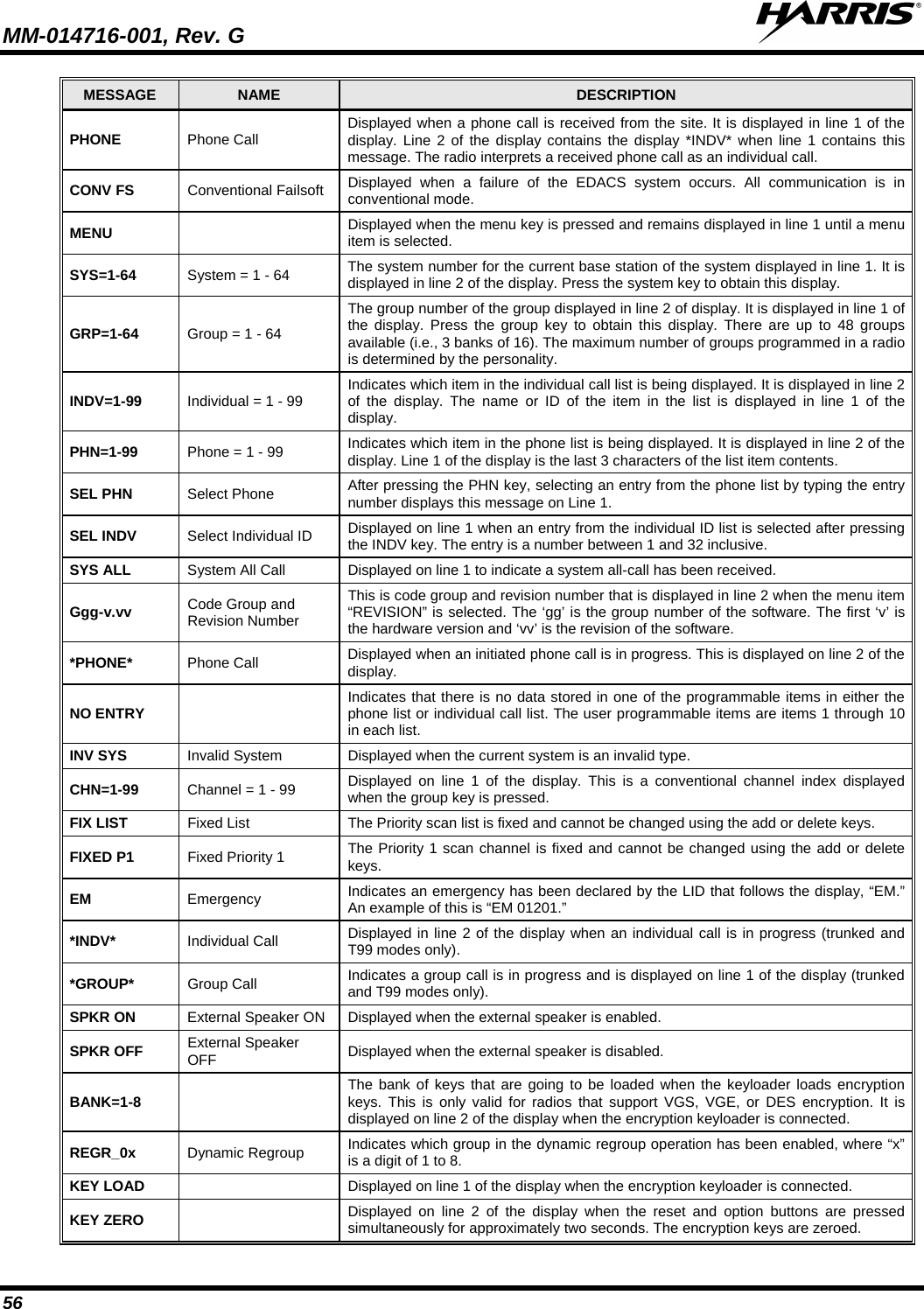
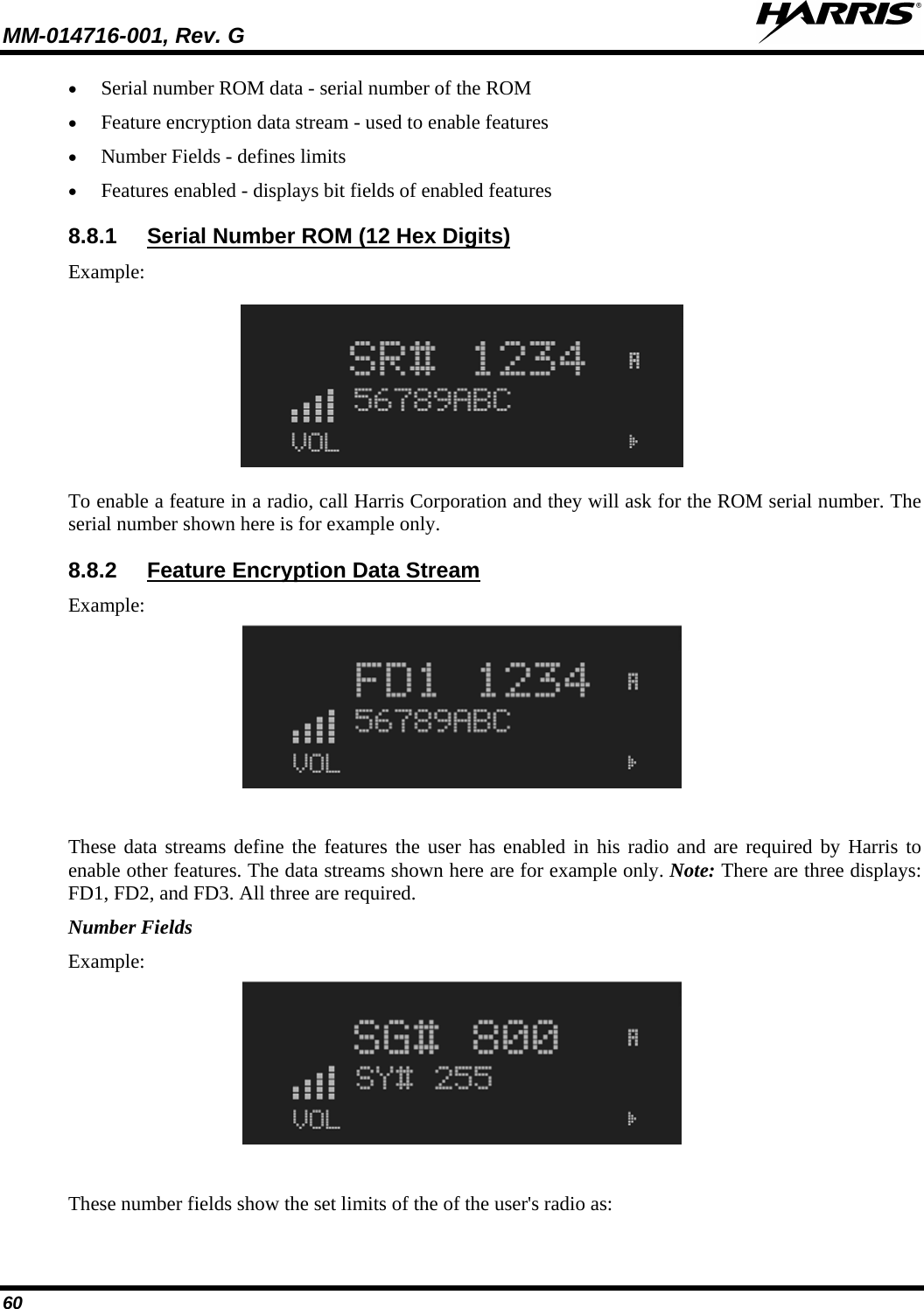
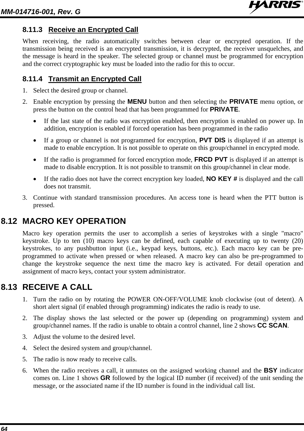
![MM-014716-001, Rev. G 44 declaring radio’s microphone remains “hot” for a predetermined amount of time. In other words, the radio transmits audio for a period of time even when the microphone’s PTT button is not pressed. An emergency talk group is provided greater priority and infinite hang-time by the radio system’s infrastructure. Hang-time is the maximum duration of quiet time between transmissions on the talk group before the infrastructure assets are automatically taken away. Because an emergency call is handled on a talk group, it is received by all radios and consoles monitoring the talk group. An emergency alert is a data message sent by the radio to the MIS console (or any console capable of receiving it). It identifies the radio declaring the emergency, and the radio’s location (if the radio is equipped with a GPS receiver). Voice audio is not automatically transmitted during the emergency if the administrator configures the radio for alert notification only. 7.31.1 1. Press the red emergency button on the radio to enter emergency mode. The emergency is raised after the emergency raise delay [default is one (1) second]. Declare an Emergency Call or Alert • If the active profile of the unit initiating the emergency is configured for Emergency Alert, the emergency alert signal is sent to registered alert servers, such as the dispatcher console. • If the active profile of the unit initiating the emergency is configured for Emergency Call, the talkgroup is placed into emergency status notifying other radios and the emergency alert signal is sent to the dispatcher console. • If the emergency behavior of the active profile is Current, the active, selected voice group becomes the default emergency voice group. • If the emergency behavior of the active profile is Default, the radio moves to the default emergency voice group of the profile and this talk group becomes the select talk group. 2. The display alternates between “Emergency” and whatever option is selected for the 2nd line of the dwell display. If the attempt is unsuccessful, “E-PEND” flashes periodically and a retry is queued for 10 seconds. If unsuccessful because of lost sync, retry occurs immediately upon reacquiring sync. On each retry attempt, radio temporarily displays “E-RETRY.” This process repeats until the emergency is successfully declared. 7.31.2 When this feature is enabled and an emergency call or alert is declared by pressing the emergency button, the radio does not play a tone and displays an abbreviated emergency message (default is EBA). This feature is enabled or disabled via programming or via the menu. Silent Emergency NOTE If the Silent Emergency feature is enabled or disabled via programming, the setting survives power cycle. Enable/Disable selection via the menu do NOT survive power cycle and the enable/disable state reverts to the programmed setting at power up.](https://usermanual.wiki/HARRIS/TR-0060-E.Manual-3/User-Guide-1507435-Page-44.png)
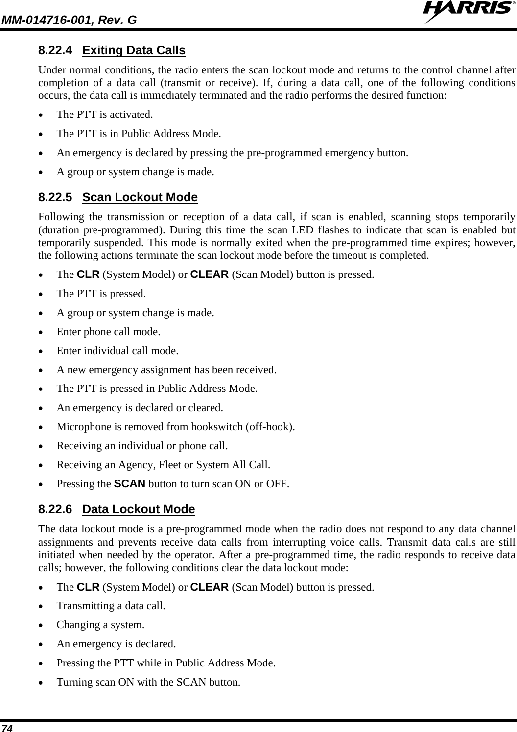
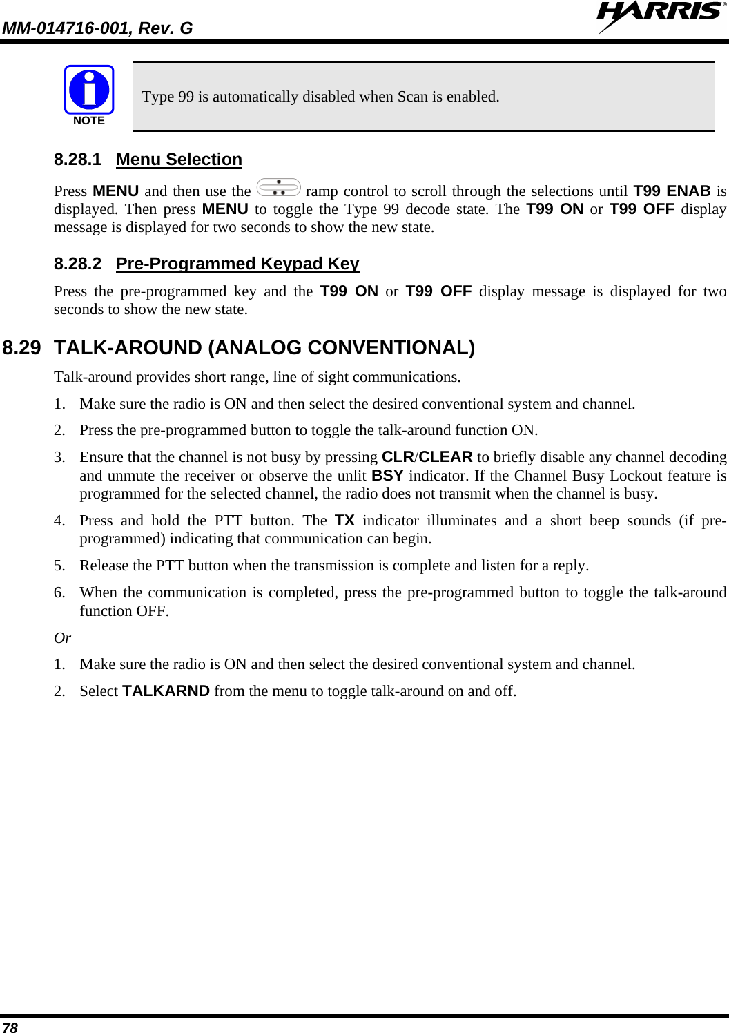
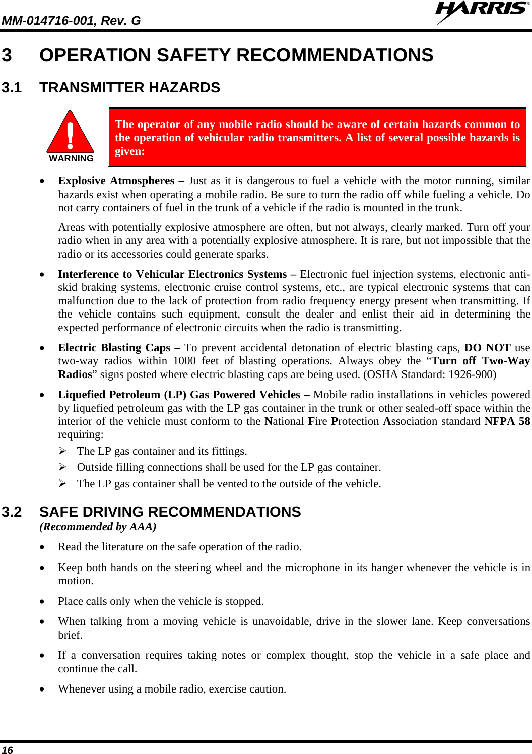
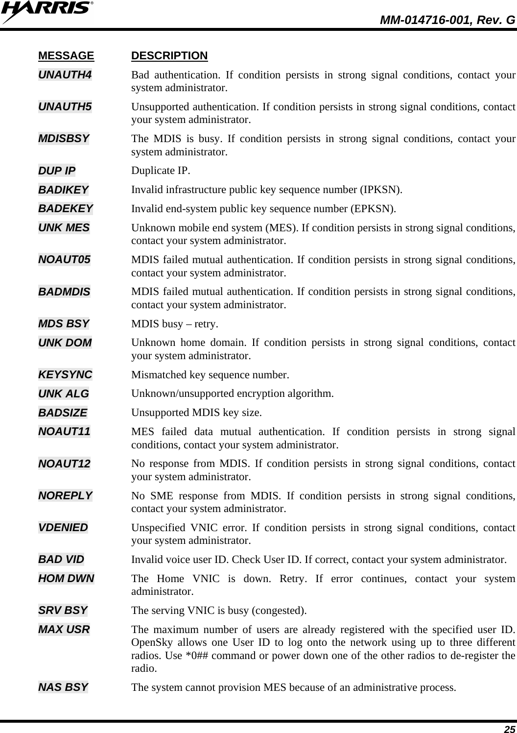
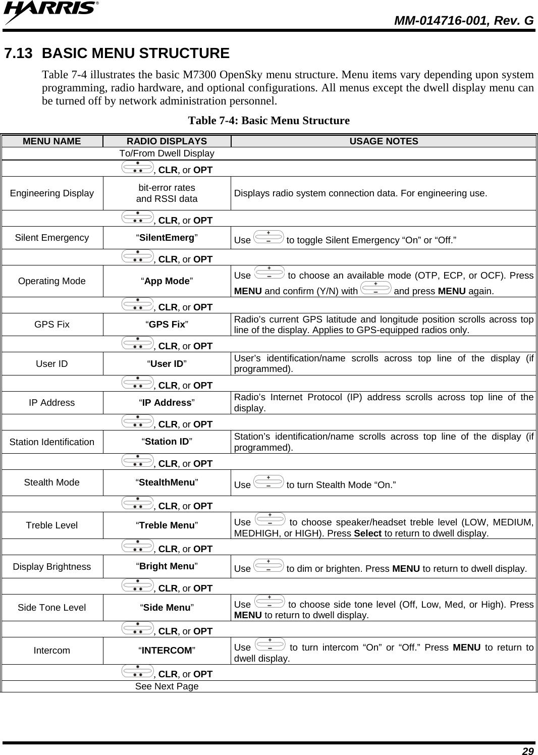
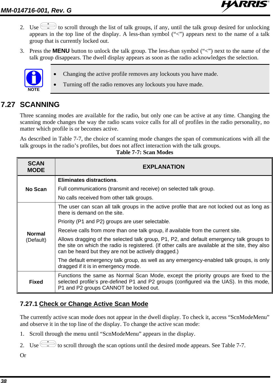
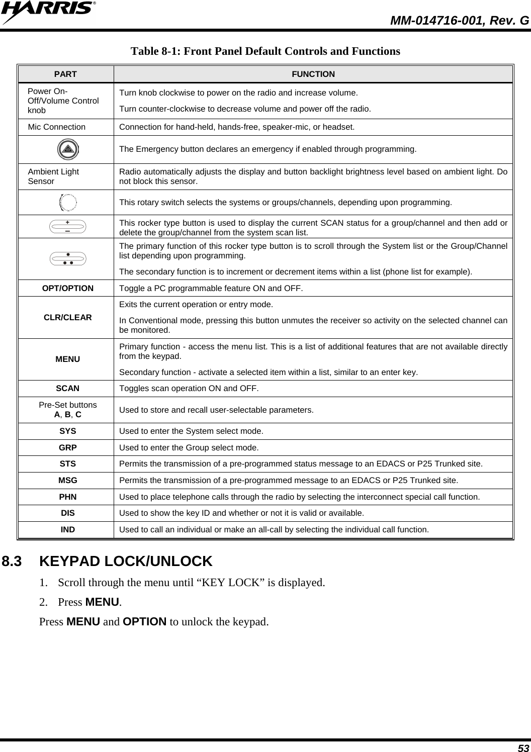
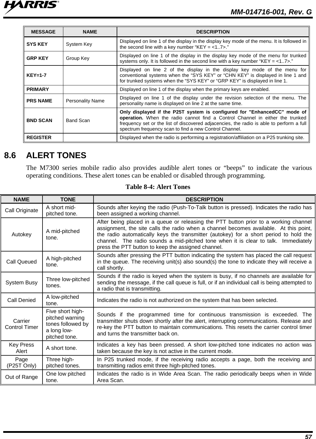
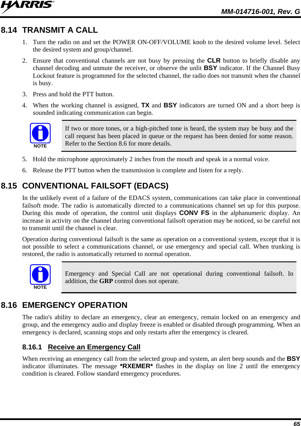
![MM-014716-001, Rev. G 50 7.37 GPS COORDINATES The radio’s current latitude and longitude coordinates may be displayed using the “GPS” menu. The following procedure assumes a GPS antenna is connected to the radio and it is receiving adequate signals from GPS satellites: 1. Scroll through the menu until the “GPS” menu appears in the bottom line of the display. Current GPS coordinate latitude and longitude data continuously scrolls in the top line of the display in a degrees:minutes:seconds format. 2. Use to change to another menu. NOTE If the internal GPS receiver’s data is expired (30 minutes or more) or unavailable, the radio uses the serving base station’s coordinates [GPS (Site) is displayed]. The GPS Menu also indicates if the data is aged (2 minutes or more) [GPS (Aged) is displayed]. 7.38 SCENE-OF-INCIDENT MODE The Scene-of-Incident mode (SOI) is user-selectable. The SOI mode provides a local repeater function (V-TAC) with no network connection CAUTION When operating in the SOI mode, the radio is disconnected from the OpenSky network. Therefore, communications with radios and dispatch personnel on the network is not possible. Enter SOI Mode Manually Entering the Channel1. Scroll through the menu until the Client Mode menu appears. : 2. Using , scroll until SOI is displayed. 3. Press the MENU button to confirm mode selection. 4. Using , scroll until “Manual Select Chan” is displayed and press MENU. 5. Using , scroll to edit the right-most digit and press MENU to advance to the next digit. Repeat until the desired channel is entered. 6. The radio then prompts the user to edit the band. Use to edit the number assigned to the frequency band and press MENU to confirm and enter the SOI mode. Use the Client Mode menu to return to normal operation (Network Mode). The personality and profile in use at the time the radio entered SOI mode is restored. Enter SOI Mode Selecting Pre-Programmed Channel1. Scroll through the menu until the Client Mode menu appears. : 2. Using , scroll until SOI is displayed. 3. Press MENU to confirm mode selection. 4. Using , scroll through a list of pre-programmed channels. 5. Press MENU to confirm channel and enter SOI mode.](https://usermanual.wiki/HARRIS/TR-0060-E.Manual-3/User-Guide-1507435-Page-50.png)
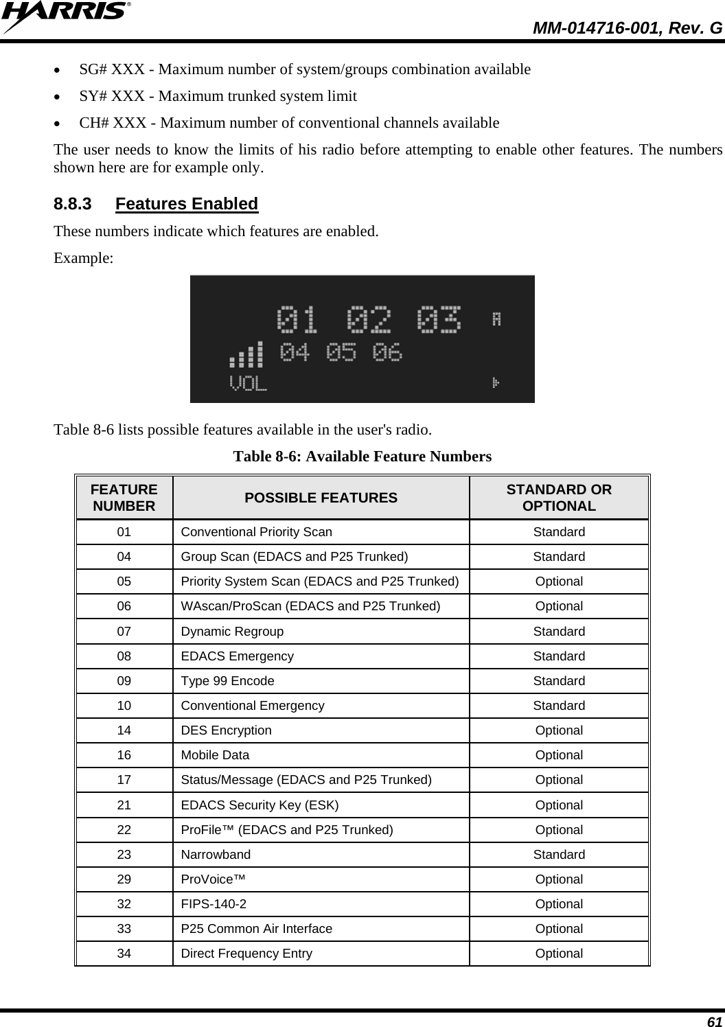
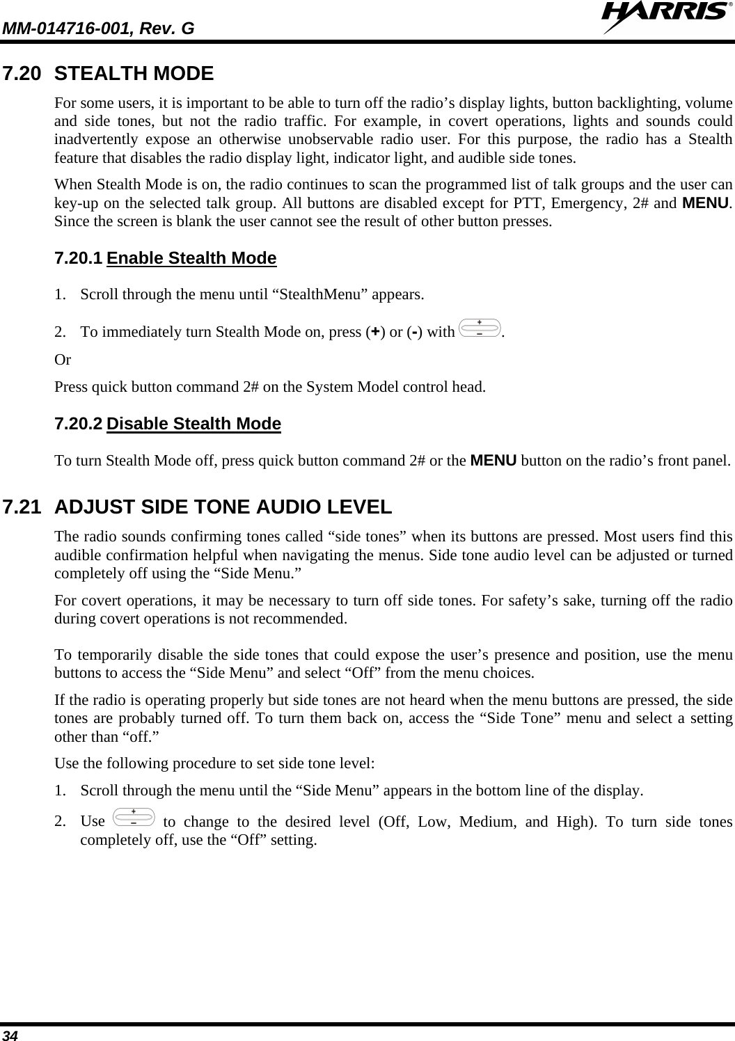
![MM-014716-001, Rev. G 66 8.16.2 To send an emergency call to the selected system and group (or on an optionally pre-programmed emergency group), proceed as follows: Declare an Emergency 1. Press and hold the red emergency button for approximately one second. (This time is programmable and therefore could be longer or shorter. Check with the system administrator.) The radio transmits an emergency call request with the radio ID until an emergency channel assignment is received. 2. When the working channel assignment is received, the radio sounds a single beep (Autokey alert tone) indicating it is ready for voice transmission. *TXEMER* flashes on line 2 in the display until the emergency is cleared. 3. Press PTT and speak into the microphone in a normal voice. 4. Release PTT when the transmission is complete and listen for a reply. 5. The emergency can be cleared by pressing and holding the CLR button followed by pressing the red emergency button then releasing both buttons. 8.17 SYSTEM SCAN OPERATION (EDACS AND P25 TRUNKED) The radio can be programmed with the following System Scan features. These features are automatically enabled upon radio power up. A key or menu option is also defined to allow the System Scan features to be toggled during radio operation. This is covered in the Menu Selection and Pre-Programmed Keypad Key sections. The System Scan state is maintained through system changes but defaults to ON at power up. 8.17.1 The M7300 Series mobile radio can be programmed for Wide Area System Scan operation for multi-site applications. Upon the loss of the currently selected system's control channel, radios can be programmed to automatically scan the control channels of other systems. If a new control channel is found, the radio switches to the new system and sounds an alert tone. Wide Area System Scan (WA Scan) 8.17.2 The radio can be programmed for ProScan™ system scan operation for multi-site applications depending on the version of radio flash code. ProScan provides the radio with the ability to select a new system for the radio to communicate on, when the selected system drops below a predefined level. This is accomplished by enabling each radio to analyze the signal quality of its current control channel and compare it with the signal quality of the control channel for each site in its adjacency scan list. The signal quality metric used for the ProScan algorithm is based on a combination of both Received Signal Strength Indicator [RSSI] and Control Channel Verification [CCV] measurements. When the selected system’s signal quality level degrades below a pre-programmed level, the radio begins to look for a better control channel. Once a control channel that exceeds the pre-programmed parameters is found, the radio changes to the new system and emits a tone. If the control channel is completely lost, the radio enters Wide Area System Scanning and searches the programmed adjacent systems until a suitable control channel is found. ProScan™ 8.17.3 The radio can also be programmed for Priority System Scan. (To ensure that this feature operates correctly, the control channel of the priority system must be located on channel one unless you are using the ProScan algorithm.) The priority system is the desired or preferred system. While receiving the control channel of the selected system, the radio periodically leaves the selected system and searches for Priority System Scan](https://usermanual.wiki/HARRIS/TR-0060-E.Manual-3/User-Guide-1507435-Page-66.png)