HARRIS TR-0063-E 800 MHz SG5300 User Manual Manual
HARRIS CORPORATION 800 MHz SG5300 Manual
HARRIS >
Manual


Product Manual
MM-018623-001
Jul/11
SG5300 Data Modem
800 MHz and 900 MHz

MM-018623-001
2
MANUAL REVISION HISTORY
REV DATE REASON FOR CHANGE
- Jul/11 Initial release.
CREDITS
Harris, assuredcommunications, EDACS, and OpenSky are registered trademarks and NetworkFirst is a trademark of Harris
Corporation.
Conxall and Multi-Con-X are registered trademarks of Conxall Inc.
Band-it is a registered trademark of BAND-IT-IDEX, Inc. A Unit of IDEX Corporation
All other brand and product names are trademarks, registered trademarks, or service marks of their respective owners.
NOTICE!
The material contained herein is subject to U.S. export approval. No export or re-export is permitted without written approval
from the U.S. Government. Rated: EAR99; in accordance with U.S. Dept. of Commerce regulations 15CFR774, Export
Administration Regulations.
Information and descriptions contained herein are the property of Harris Corporation. Such information and descriptions may
not be copied or reproduced by any means, or disseminated or distributed without the express prior written permission of
Harris Corporation, PSPC Business, 221 Jefferson Ridge Parkway, Lynchburg, VA 24501.
Repairs to this equipment should be made only by an authorized service technician or facility designated by the supplier. Any
repairs, alterations or substitutions of recommended parts made by the user to this equipment not approved by the
manufacturer could void the user's authority to operate the equipment in addition to the manufacturer's warranty.
This product conforms to the European Union WEEE Directive 2002/96/EC. Do not dispose of this
product in a public landfill. Take it to a recycling center at the end of its life.
This manual is published by Harris Corporation
without any warranty. Improvements and changes to this manual
neces
sitated by typographical errors, inaccuracies of current information, or improvements to programs and/or equipment,
may be made by Harris Corporation
at any time and without notice. Such changes will be incorporated into new editions of
this manual. No par
t of this manual may be reproduced or transmitted in any form or by any means, electronic or mechanical,
including photocopying and recording, for any purpose, without the express written permission of Harris Corporation.
Copyright © 2011, Harris Corporation. All rights reserved.

MM-018623-001
3
SOFTWARE LICENSE AGREEMENT
THE SOFTWARE PROGRAM PROVIDED WITH THIS DOCUMENT IS FURNISHED UNDER A LICENSE AND MAY
BE USED ONLY IN ACCORDANCE WITH THE FOLLOWING LICENSE TERMS.
Harris Corporation RF Communications Division, hereafter referred to as COMPANY, grants to you, hereafter referred to as
USER, a non-exclusive, paid up license to use the accompanying Software, the media on which it is recorded, and
Programming Guide, all hereafter referred to as PRODUCT, for use under the following terms and conditions:
1. The techniques, algorithms, and processes contained in the PRODUCT constitute trade secrets of COMPANY. USER
agrees not to provide or otherwise make available any PRODUCT to any third party and to take all measures reasonable
and necessary to protect the confidentiality of the PRODUCT and COMPANY's rights herein. The foregoing shall not
apply to any PRODUCT which USER can show was in its possession prior to the disclosure made by COMPANY, or
which subsequently came into its possession through channels independent of COMPANY, or was independently
developed by employees of USER who had not had access to PRODUCTS, or which appears in a printed publication
other than as a breach of any obligation owed to COMPANY, or with the prior written permission of COMPANY.
2. USER shall not reproduce or copy the PRODUCT, make or permit any change or modification, in whole or in part, in its
original or any other language, or permit anyone else to do so for any purpose whatsoever, except as necessary for the
USER:
a. This PRODUCT is for use on the single computer for which it is licensed here under.
b. Except for Key Loader – to use it within the organization on multiple computers for which it is licensed here under.
3. USER shall not transfer the PRODUCT or any part thereof. This license does not include the right to sublicense and may
not be assigned.
4. The PRODUCT is copyrighted under United States and International laws by COMPANY. USER agrees not to remove
any COMPANY copyright, trademark or other notices or PRODUCT identification.
5. If USER does not comply with all of the terms and conditions of this license agreement, COMPANY may terminate this
license and require USER to return the PRODUCT. USER's liability shall include, but not be restricted to, all costs
incurred by COMPANY in recovering the PRODUCT and all damages arising from USER's default.
6. USER shall be solely responsible for determining the appropriate use to be made of the PRODUCT in USER's own
operations. PRODUCTS ARE DISTRIBUTED "AS IS" WITHOUT WARRANTY OF ANY KIND, EITHER
EXPRESSED OR IMPLIED.
7. USER is responsible to insure that use of the PRODUCT to install or repair COMPANY equipment meets all standards
and regulations required by federal, state and local governments and that the operator of that mobile radio
communications equipment is legally licensed for the use of the frequencies programmed into the radio equipment.
8. In no event, whether on warranty, contract or negligence, shall COMPANY be liable for special, incidental, indirect or
consequential damages including, but not limited to, loss of profits or revenue, loss of use of any equipment, cost of
capital, or any other loss that may result directly or indirectly from use of PRODUCTS or from failure of PRODUCTS to
operate as intended.
9. The COMPANY cannot support software unless the specifications on the machine comply with COMPANY
requirements in the COMPANY Software Release Notes.
ECR-7378B

MM-018623-001
4
TABLE OF CONTENTS
Section Page
1 REGULATORY AND SAFETY INFORMATION .................................................................... 7
1.1 REGULATORY APPROVALS ............................................................................................ 7
1.1.1 Transmitter ............................................................................................................... 7
1.1.2 Receiver .................................................................................................................... 7
1.1.3 FCC Compliance ...................................................................................................... 7
1.1.4 Industry Canada ........................................................................................................ 7
1.2 SAFETY SYMBOL CONVENTIONS ................................................................................. 8
1.3 RF ENERGY EXPOSURE INFORMATION ....................................................................... 9
1.3.1 Safety Training Information ..................................................................................... 9
1.3.2 Contact Information ................................................................................................ 10
1.3.3 Occupational Safety Guidelines and Safety Training Information ......................... 10
2 INTRODUCTION ........................................................................................................................ 11
2.1 ABOUT THIS MANUAL ................................................................................................... 11
2.2 GLOSSARY OF TERMS .................................................................................................... 11
3 DESCRIPTION ............................................................................................................................ 12
3.1 MULTIPLE APPLICATIONS ............................................................................................ 12
3.2 OVER-THE-AIR PROGRAMMING .................................................................................. 13
3.3 VERSATILE MOUNTING ................................................................................................. 14
3.4 DNP3 ................................................................................................................................... 14
4 OPERATION ............................................................................................................................... 15
4.1 STARTING SG5300 ........................................................................................................... 15
4.2 INDICATORS ..................................................................................................................... 16
5 UNPACKING AND CHECKING EQUIPMENT ..................................................................... 17
5.1 UNPACKING EQUIPMENT .............................................................................................. 17
5.2 INSPECTING AND INVENTORYING EQUIPMENT ..................................................... 17
5.3 ITEMS INCLUDED ............................................................................................................ 17
5.4 OPTIONS AND ACCESSORIES ....................................................................................... 18
6 INSTALLATION ......................................................................................................................... 19
6.1 GENERAL PLANNING ..................................................................................................... 19
6.2 SITE GROUNDING ............................................................................................................ 19
6.3 EQUIPMENT INSTALLATION ........................................................................................ 20
6.4 MOUNTING THE SG5300 ................................................................................................. 20
6.5 CONNECTIONS
................................................................................................................. 22
6.5.1 Power Connections ................................................................................................. 22
6.5.2 Safety/Earth Ground ............................................................................................... 23
6.5.3 Ethernet Data Interface Connection ....................................................................... 24
6.5.4 Serial Data Interface Connection ............................................................................ 25
6.6 ANTENNA INSTALLATION ............................................................................................ 25
6.7 SURGE PROTECTION ...................................................................................................... 25
7 CONFIGURATION ..................................................................................................................... 27
7.1 EQUIPMENT REQUIRED ................................................................................................. 27
7.2 CONFIGURING THE RF RADIO ...................................................................................... 27
7.3 CONFIGURING THE ETHERNET PORT ......................................................................... 29
8
SOFTWARE INSTALLATION ................................................................................................. 31

MM-018623-001
5
TABLE OF CONTENTS
Section Page
8.1
DOWNLOAD
SOFTWARE ............................................................................................... 31
8.1.1 Set Server IP Address ............................................................................................. 31
8.1.2 Install Software ....................................................................................................... 31
8.2 CONFIGURATION ............................................................................................................ 32
8.2.1 Set Server IP Address ............................................................................................. 32
8.2.2 Serial Channel and Network configuration ............................................................ 33
8.2.3 Load Factory Defaults ............................................................................................ 37
8.3 IMPLEMENTATION ......................................................................................................... 37
8.3.1 Sample Implementation, SG5300 and One Logical Network ................................ 40
8.3.2 Sample Implementation, SG5300 and Two Logical Networks .............................. 42
8.3.3 Sample Implementation, SG5300, 2 logical networks, and Multiple Devices ....... 44
9 TROUBLESHOOTING AND SERVICING ............................................................................. 47
9.1 TROUBLESHOOTING ...................................................................................................... 47
9.2 SERVICING ........................................................................................................................ 47
10 CUSTOMER SERVICE .............................................................................................................. 48
10.1 TECHNICAL ASSISTANCE ............................................................................................. 48
10.2 CUSTOMER CARE ............................................................................................................ 48
11 SPECIFICATIONS ...................................................................................................................... 49
11.1 GENERAL SPECIFICATIONS .......................................................................................... 49
11.2 TRANSMITTER SPECIFICATIONS ................................................................................. 50
11.3 RECEIVER SPECIFICATIONS ......................................................................................... 50
11.4 DIGITAL OPERATION ..................................................................................................... 50
12 WARRANTY................................................................................................................................ 51

MM-018623-001
6
LIST OF FIGURES
Page
Figure 3-1: SG5300 Data Modem ....................................................................................................... 12
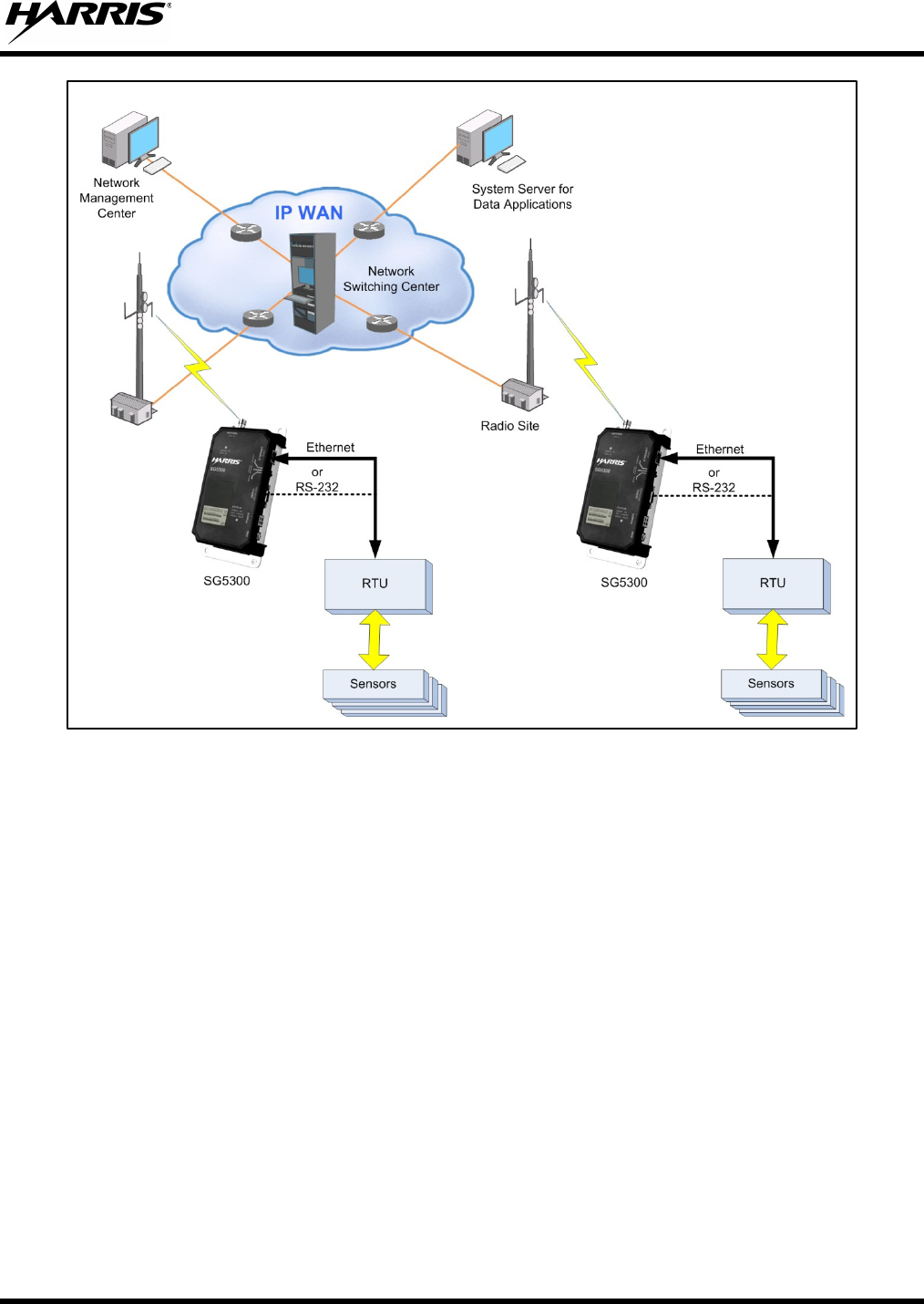
Figure 3-2: SG5300 System Application ............................................................................................. 13
Figure 3-3: DNP3 Protocol Example ................................................................................................... 14
Figure 4-1: SG5300 Controls and Indicators ....................................................................................... 15
Figure 6-1: SG5300 Physical Dimensions ........................................................................................... 21
Figure 8-1: SG5300 and One logical network ..................................................................................... 40
Figure 8-2: SG5300 and Two Logical Networks ................................................................................ 42
Figure 8-3: SG5300, Two Logical Networks, and Multiple Devices .................................................. 44
LIST OF TABLES
Page
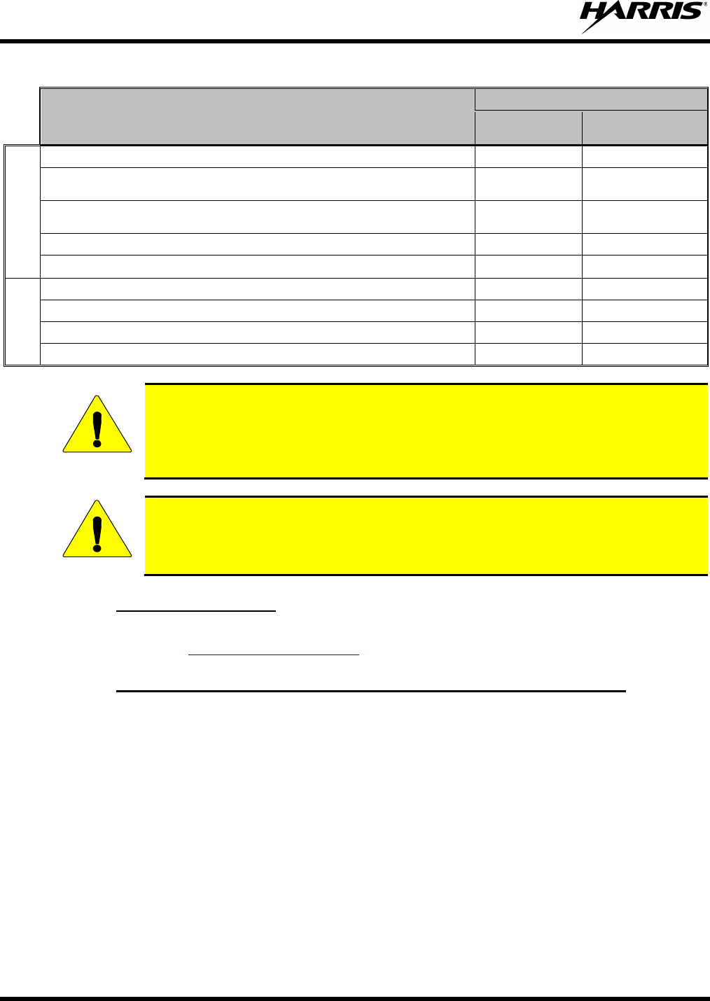
Table 1-1: MPE Table ......................................................................................................................... 10
Table 2-1: Glossary of Terms .............................................................................................................. 11
Table 4-1: Indicators and Controls ...................................................................................................... 16
Table 6-1: Ethernet Interface Signals .................................................................................................. 24
Table 6-2: Ethernet LEDs .................................................................................................................... 24
Table 6-3: Serial Interface Signals ...................................................................................................... 25
Table 6-4: Surge Protection Options ................................................................................................... 26
Harris Corporation, Public Safety and Professional Communications (PSPC) Business continually evaluates its technical
publications for completeness, technical accuracy, and organization. You can assist in this process by submitting your
comments and suggestions to the following:
Harris Corporation fax your comments to: 1-434-455-6851
PSPC Business or
Technical Publications e-mail us at: PSPC_TechPubs@harris.com
221 Jefferson Ridge Parkway
Lynchburg, VA 24501

MM-018623-001
7
1 REGULATORY AND SAFETY INFORMATION
1.1 REGULATORY APPROVALS
1.1.1 Transmitter
The transmitting devices listed below have been tested and meet the following regulatory requirements:
MODEL DESCRIPTION FCC ID
(PART 90) INDUSTRY CANADA
(RSS-119)
SG5300-800 RU-019026-800 Radio Unit OWDTR-0063-E 3636B-0063
SG5300-900 RU-019026-900 Radio Unit OWDTR-0064-E 3636B-0064
1.1.2 Receiver
This receiver associated with this transmitting device has been tested and declared to meet the regulatory
requirements defined in the following sub-sections. Associated FCC labelling may be found on page 2.
1.1.3 FCC Compliance
This device complies with Part 15 of the FCC Rules. Operation is subject to the following two
conditions:
1. This device may not cause harmful interference, and
2. This device must accept any interference received, including interference that may cause undesired
operation.
1.1.4 Industry Canada
Le présent appareil est conforme aux CNR d'Industrie Canada applicables aux appareils radio exempts de
licence. L'exploitation est autorisée aux deux conditions suivantes:
1. l'appareil ne doit pas produire de brouillage, et
2. l'utilisateur de l'appareil doit accepter tout brouillage radioélectrique subi, même si le brouillage est
susceptible d'en compromettre le fonctionnement.
WARNING
The installer of this SG5300 must ensure that the antenna is located or pointed such
that it does not emit RF field in excess of Health Canada limits for the general
population; consult Safety Code 6, obtainable from Heath Canada’s website www.hc-
sc.gc.ca/rpb.

MM-018623-001
8
1.2 SAFETY SYMBOL CONVENTIONS
The following conventions may be used in this manual to alert the user to general safety precautions that
must be observed during all phases of operation, service, and repair of this product. Failure to comply
with these precautions or with specific warnings elsewhere in this manual violates safety standards of
design, manufacture, and intended use of the product. Harris Corporation assumes no liability for the
customer's failure to comply with these standards.
WARNING
The WARNING symbol calls attention to a procedure, practice, or the like, which,
if not correctly performed or adhered to, could result in personal injury. Do not
proceed beyond a WARNING symbol until the conditions identified are fully
understood or met.
CAUTION
The CAUTION symbol calls attention to an operating procedure, practice, or the like,
which, if not performed correctly or adhered to, could result in a risk of danger, damage
to the equipment, or severely degrade the equipment performance.
NOTE
The NOTE
symbol calls attention to supplemental information, which may improve
system performance or clarify a process or procedure.
The ESD symbol calls attention to procedures, practices, or the like, which could expose
equipment to the effects of Electro-Static Discharge. Proper precautions must be taken
to prevent ESD when handling circuit modules.
The electrical hazard symbol is a WARNING indicating there may be an electrical
shock hazard present.
This symbol indicates the presence of a potential RF hazard.

MM-018623-001
9
1.3 RF ENERGY EXPOSURE INFORMATION
CAUTION
To ensure that exposure to RF electromagnetic energy is within the FCC allowable
limits for occupational use, always adhere to the following guidelines:
• DO NOT operate the SG5300 without a proper antenna attached, as this may damage the SG5300 and
may also cause the FCC RF exposure limits to be exceeded. A proper antenna is the antenna supplied
with this SG5300 by Harris Corporation or an antenna specifically authorized by Harris for use with
this SG5300.
• DO NOT transmit for more than 50% of total RADIO use time (“50% duty cycle”). Transmitting
more than 50% of the time can cause FCC RF exposure compliance requirements to be exceeded.
The SG5300 is transmitting when the “TX” indicator appears in the display.
• Always transmit using low power when possible.
1.3.1 Safety Training Information
YOUR HARRIS SG5300 GENERATES RF ELECTRO-MAGNETIC ENERGY
DURING TRANSMIT MODE. THIS SG5300
IS DESIGNED FOR AND
CLASSIFIED AS “OCCUPATIONAL USE ONLY,” MEANING IT MUST BE
USED ONLY IN THE COURSE OF EMPLOYMENT BY INDIVIDUALS
AWARE OF THE HAZARDOUS RF ENERGY AND THE WAYS TO
MINIMIZE EXPOSURE. THIS STATION IS NOT INTENDED FOR USE BY
THE “GENERAL POPULATION” IN AN UNCONTROLLED ENVIRONMENT.
IT IS THE RESPONSIBILITY OF THE LICENSEE TO ENSURE THAT THE
MAXIMUM PERMISSIBLE EXPOSURE LIMITS ARE OBSERVED AT ALL
TIMES DURING TRANSMISSION. THE STATION LICENSEE
IS TO
ENSURE THAT NO BYSTANDERS COME WITHIN THE RADIUS OF THE
LIMITS.
When licensed by the FCC, this device complies with the FCC RF exposure limits when persons are
beyond the MPE radius of the antenna (see Table 1-1). In addition, your Harris SG5300 installation
complies with the following Standards and Guidelines with regard to RF energy and electromagnetic
energy levels and evaluation of such levels for exposure to humans:
FCC OET Bulletin 65 Edition 97-01 Supplement C, Evaluating Compliance with FCC Guidelines
for Human Exposure to RADIO Frequency Electromagnetic Fields.
American National Standards Institute (C95.1 – 1992), IEEE Standard for Safety Levels with
Respect to Human Exposure to RADIO Frequency Electromagnetic Fields, 3 kHz to 300 GHz.
American National Standards Institute (C95.3 – 1992), IEEE Recommended Practice for the
Measurement of Potentially Hazardous Electromagnetic Fields – RF and Microwave.
MM-018623-001
10
Table 1-1: MPE Table
Antenna
Safe Distance, Rsafe, (cm)
Controlled
Environment
Uncontrolled
Environment
800 MHz
AN-225001-001 3 dBd (5.15 dBi) dual band roof mount antenna
20
20
AN-225001-002 3 dBd (5.15 dBi) dual band elevated feed point
antenna
20
20
AN-225001-003 3 dBd (5.15 dBi) dual band elevated feed point
antenna
20
20
AN-225001-004 2 dBd (4.15 dBi) low profile antenna
20
25
AN-225001-005 5 dBd (7.15 dBi) dual band roof mount
20
20
900 MHz
AN-225005-001 3 dBd (5.15 dBi) roof mount
20
20
AN-225005-002 3 dBd (5.15 dBi) elevated feed roof mount antenna
20
20
AN-225005-003 3 dBd (5.15 dBi) elevated feed roof mount antenna
20
20
AN-225005-004 2 dBd (4.15 dBi) low profile antenna
20
25
CAUTION
To ensure that your exposure to RF electromagnetic energy is within the FCC
allowable limits for occupational use, do not operate the station in a manner that
would create an MPE distance in excess of that allowable by the FCC.
CAUTION
Changes or modifications not expressly approved by Harris Corporation could
void the user’s authority to operate the equipment.
1.3.2 Contact Information
For additional information on exposure requirements or other information, contact Harris Corporation at
1-800-528-7711 or at http://www.pspc.harris.com.
1.3.3 Occupational Safety Guidelines and Safety Training Information
To ensure bodily exposure to RF electromagnetic energy is within the FCC allowable limits for
occupational use. Always adhere to the following basic guidelines:
1. The SG5300 should only be used for necessary work-related communications.
2. The SG5300 should only be used by authorized and trained personnel.
3. Do not attempt any unauthorized modification to the SG5300. Changes or modifications to the
SG5300 may cause harmful interference and/or cause it to exceed FCC RF exposure limits. Only
qualified personnel should service the SG5300.
4. Always use Harris authorized accessories (antennas, control heads, speakers/mics, etc.). Use of
unauthorized accessories can cause the FCC RF exposure compliance requirements to be exceeded.
The information listed above provides the user with information needed to make him or her aware of a RF
exposure, and what to do to assure that this SG5300 operates within the FCC exposure limits of this radio.

MM-018623-001
11
2 INTRODUCTION
2.1 ABOUT THIS MANUAL
This manual is written for the communications professional responsible for installing and maintaining the
SG5300 Data Modem.
2.2 GLOSSARY OF TERMS
The following Table is a list of terms used in this manual.
Table 2-1: Glossary of Terms
TERM
DEFINITION
AES Advanced Encryption Standard
RSA Rivest, Shamir, and Adleman (creators of RSA Encryption format)
DES Digital Encryption Standard
DHCP Dynamic Host Configuration Protocol
EDACS Enhanced Digital Access Communications System
GPS Global Positioning Satellite
IEEE Institute of Electrical & Electronics Engineers
LMR Land Mobile Radio
MIB Management Information Base
QoS Quality of Service
SNMP Simple Network Management Protocol
TAC Technical Assistance Center
TFTP Trivial File Transfer Protocol
UAS Unified Administration System
UGS Unsolicited Grant Services
VIDA Voice, Interoperability, Data, and Access
WAN Wide Area Network

MM-018623-001
12
3 DESCRIPTION
The SG5300 Data Modem is part of the OpenSky® suite of products which delivers very high capacity,
end-to-end digital data communication. The small and lightweight unit is housed in a plastic case for
mounting indoors or in a NEMA enclosure and is designed to provide reliable, secure, and cost effective
data communications to and from remote locations.
Figure 3-1: SG5300 Data Modem
3.1 MULTIPLE APPLICATIONS
The SG5300 is suitable for a wide range of applications. The substantial coverage of an OpenSky private
wireless network means that the SG5300 can be useful to collect or distribute data messages in locations
where other wireless technologies are either not available or not reliable enough. Utilities will find it an
excellent means of communication with line reclosers, capacitor banks, and other devices on the grid.
Transportation applications include automated signs, bus stop kiosks, and connection with remote traffic
flow and weather sensors. Public safety agencies can use it to send alarms for public notification of
severe weather, emergencies, or for a host of other applications.
MM-018623-001
13
Figure 3-2: SG5300 System Application
The SG5300 provides a choice of Ethernet (RJ45) or Serial (DB9) interface to remote terminals. Its 3-
Watt RF output makes it a compact and cost-effective wireless link that can easily fit alongside Remote
Terminal Units (RTUs) and other devices.
The SG5300 is capable of interfacing to RTUs via an Ethernet 10/100Base-T interface port or TIA/EIA-
232 Serial interface port. The Ethernet port is capable of operating as a data interface between the
SG5300 and external devices with MTU size of 1400 bytes or less. The Serial port is capable of
operating as the data interface using SLIP or PPP between the SG5300 and external devices (RTUs). The
SG5300 is configured so that the data interface is with either the Ethernet port or the Serial port, but not
both simultaneously.
The Serial port is also used as a maintenance port to configure the RF radio, software loading, and
configuration of the Ethernet port. However, the Serial port is not available for maintenance use while
external devices are connected to the Ethernet port.
3.2 OVER-THE-AIR PROGRAMMING
As an OpenSky radio, the SG5300 benefits from a flexible, software-based design. Features, profiles, and
system updates are software-defined and can be reprogrammed over the air.
MM-018623-001
14
3.3 VERSATILE MOUNTING
The SG5300 is designed to be mounted indoors or in a NEMA enclosure.
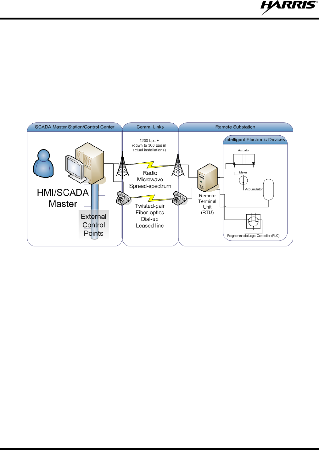
3.4 DNP3
A common protocol used between the System Server and RTUs is DNP3. DNP3 (Distributed Network
Protocol) is intended for communications between RTU, IED, and controller devices in SCADA
networks. It is a more general protocol than IEC 60870-5-104 and is used in the electrical distribution,
water infrastructure, oil and gas, waste water, and security industries.
Figure 3-3: DNP3 Protocol Example
In 1993 GE-Harris Canada used the partially completed IEC 60870-5 protocol specification as the
basis for an open and immediately implementable protocol that specifically catered to North
American requirements. This new protocol became DNP3. Today DNP3 has a strong following
worldwide except for Europe where IEC 60870-5 dominates.
DNP3 is a layer 2 protocol which is commonly tunneled through TCP/IP, with an Ethernet interface.

MM-018623-001
15
4 OPERATION
In-service operation of the SG5300 is completely automatic. Once the unit is properly installed and
configured, local unit operation can be observed by viewing the Status LEDs for proper operation.
After properly installing the unit, operational control and monitoring can be made from the Network
Management Center and the Centralized System Server.
4.1 STARTING SG5300
Start the radio operation by following these steps:
1. Apply DC power to the transceiver.
2. Observe the Status LEDs for the proper indications (Table 4-1).
Figure 4-1: SG5300 Controls and Indicators
MM-018623-001
16
4.2 INDICATORS
The SG5300 RF Radio unit has two tri-color LEDs which indicate its operating status. The Unit Status
LED, located near the power connector, indicates Power On or Normal Operation (amber or orange). It
also indicates when the unit is in the Configure Ethernet mode (red) or is booting up (green).
The Radio Status LED, located near the antenna connector, indicates the operational status of the radio
section. This LED indicates whether data is being transmitted (red), received (green) or other support
functions (orange).
Table 4-1: Indicators and Controls
INDICATOR INDICATOR COLOR DESCRIPTION
Radio Status LED
OFF No Status
Blinking
GREEN Receiving RF Signal
Blinking
RED Transmitting RF Signal
Blinking
AMBER Data Registration Failure and/or
Loss of Sync
Solid
AMBER Offline
Unit Status LED
OFF
No Power Applied
AMBER Normal Operation
GREEN Booting Up
RED
Configure Ethernet
CONTROL POSITION DESCRIPTION
Configuration
Switch (Config)
Ethernet Selects Ethernet Port for data
interface.
Config Ethernet Allows you to configure the
Ethernet port settings using an
RS-232 terminal.
Serial Selects Serial Port for data
interface.
MM-018623-001
17
5 UNPACKING AND CHECKING EQUIPMENT
Before unpacking, installing, or operating the SG5300, read this section of the manual thoroughly. It
contains detailed unpacking and handling instructions, and safety precautions to protect users and
equipment.
5.1 UNPACKING EQUIPMENT
The SG5300 may be shipped in separate transit packages. The associated cabling and accessories for
each unit, if any, may also be shipped in separate containers.
When unpacking the equipment, check the contents against the packing list. Contact your Harris
representative and the carrier if any discrepancies are noted.
NOTE
Save the shipping cartons and packing materials in case the equipment needs to be
shipped back to the Harris for service.
5.2 INSPECTING AND INVENTORYING EQUIPMENT
Carefully unpack the equipment and examine each item. If there is any damage to the equipment, contact
the carrier immediately and have their representative verify the damage. If you fail to report the shipping
damages immediately, you may forfeit any claim against the carrier.
CAUTION
After removal from the carton, examine the SG5300 for broken, damaged, loose, or
missing parts. Examine the RF connector(s), power connector, and ground lug for
cracks, bent or damaged threads, or damage to any paint or seals. If any are noted,
contact the Harris Customer Care center immediately. Any unauthorized attempts to
repair or modify this equipment will void the warranty and could create a safety hazard.
5.3 ITEMS INCLUDED
The following items are included in the SG5300 package:
• RU-019026-800 Radio Unit (800 MHz)
or
• RU-019026-900 Radio Unit (900 MHz)
and
• SG5300 Data Modem Quick Guide (14221-6100-1000)

MM-018623-001
18
5.4 OPTIONS AND ACCESSORIES
MODEL/OPTION
NUMBER DESCRIPTION
Transceiver
SG5300-800 SG5300, Data Only, 800 MHz
SG5300-900 SG5300, Data Only, 900 MHz
Antennas
AN-225001-001 764-870 MHz, Dual band 3 dB gain roof mount antenna
AN-225001-002 764-870 MHz, Dual band 3 dB gain elevated feed point antenna
AN-225001-003 764-870 MHz, Dual band 3 dB gain elevated feed point antenna
AN-225001-004 764-870 MHz, Dual band 2 dB gain low profile antenna
AN-225001-005 764-870 MHz, Dual band 5 dB gain roof mount antenna
AN-225005-001 900 MHz, 3 dB gain roof mount antenna
AN-225005-002 900 MHz, 3 dB gain elevated feed roof mount antenna
AN-225005-003 900 MHz, 3 dB gain elevated feed roof mount antenna
AN-225005-004 900 MHz, 2 dB gain low profile antenna

MM-018623-001
19
6 INSTALLATION
6.1 GENERAL PLANNING
Careful planning and preparation of any installation will always benefit the end result.
1. Always read and follow all installation instructions, local and national building and electrical codes,
and general safety rules.
2. Before beginning the installation, collect information from the Site Deployment Order (SDO) specific
to the site access such as:
• Permission to access the site.
• Important contact names and telephone numbers.
• Location of and directions to the site.
• Keys and/or lock combinations to access the site and equipment shelter (if any), or points of
contact to obtain them.
• Site entry alarm system pass-codes and/or disable keys.
• Information about work practices needed to work safely at the site.
3. Other important information that may or may not be included on the SDO includes:
• Type of mounting—NEMA case, interior wall, etc.
• Drawing or description of each site showing how and where the equipment is being installed.
• Applicable inspections completed (electrical, local build code, etc.).
• Installer must be aware of other transmitters and receivers on site that could cause interference to,
or be interfered with, by the equipment. Strong signals from, or to, co-located equipment may
inflict permanent damage to either device.
4. We recommend pre-staging the equipment to become familiar with the specific hardware and cabling,
tooling, and supplies that are needed to complete the installation.
6.2 SITE GROUNDING
Installers should review the recommended grounding procedures in the Site Grounding and Lightning
Protection Guidelines Manual, AE/LZT 123 4618/1 and ensure a suitable ground is installed between the
SG5300’s ground lug and earth ground. Grounding must also be in compliance with any local and
national electrical codes.
MM-018623-001
20
6.3 EQUIPMENT INSTALLATION
Below are the basic steps for installing the SG5300. In most cases, these steps alone are sufficient to
complete the installation. Each step references more detailed instructions contained in this manual.
1. Mount the SG5300 to a stable surface. Refer to Section 6.4 for dimensions.
2. Connect the RTU equipment to the appropriate data interface connector.
(See Section 6.5.3 for Ethernet interface or 6.5.4 for a serial interface.)
NOTE
Only one data interface connection can be used at a time.
3. Select the interface using the Configuration switch.
4. Connect the SG5300 to a suitable power source (see Section 6.5).
5. Install and orient the antenna as required (see Section 6.6).
6. Configure the SG5300 as required. Refer to Section 7 for instructions.
NOTE
The operating frequencies are not set at the factory. Determine the transmit and receive
frequencies to be used, and follow the instructions in Section 7 to program them.
6.4 MOUNTING THE SG5300
The SG5300 is typically installed in an outdoor enclosure that protects the unit from weather and where
temperature is not typically controlled. The unit may also be mounted indoors in equipment closets.
Outdoors, the SG5300 should be mounted in a customer-supplied NEMA type enclosure that can supply
the required voltage as well as the appropriate environmental conditions. See Specifications in Section
11.1 for environmental requirements.
Indoors, the SG5300 can be mounted using the mounting holes on the housing in areas of appropriate
environmental conditions.
Figure 6-1 shows the SG5300 mounting dimensions.
NOTE
The SG5300 should be mounted at least three (3) feet from human traffic.

MM-018623-001
21
Unit: mm
Figure 6-1: SG5300 Physical Dimensions
MM-018623-001
22
6.5 CONNECTIONS
CONNECTION DESCRIPTION
Input Power: WAGO, 2-pin connector for DC Power (9 to 57 VDC)
Ethernet Interface: Ethernet connector (RJ-45)
Serial Interface: Serial RS-232 connector (DB-9F)
Antenna: RF connector (TNC-F)
6.5.1 Power Connections
The SG5300 is compatible with any well-filtered 9.0 to 57 VDC power source.
CAUTION
Exceeding the maximum input voltage of 57 Volts may cause permanent damage to the
equipment.
The power interface meets the following requirements:
• Connector Type: WAGO, 2-pin
• Connector Part Number: 231-602/017-000-2
• Mating Wire: AWG 12-18 (red and black)
• Maximum Power: 20 Watts
• Input Voltage Range: 9 to 57 VDC
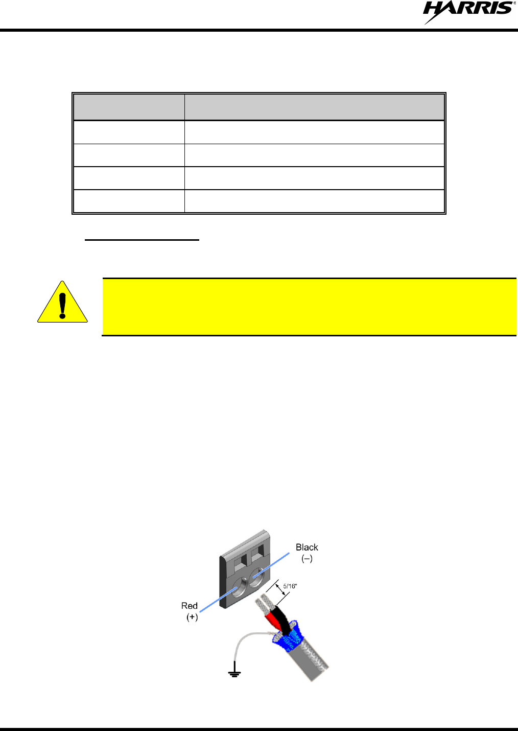
Use the following procedure to connect the power cable wires to the SG5300. The red wire (12-18
AWG) on the power cable is the positive lead; the black wire (12-18 AWG) is negative.
MM-018623-001
23
1. Route the power cable between the SG5300 and the power source.
2. At the SG5300, strip off 5/16-inch (8-9 mm) of insulation from each wire.
3. Using a small flat-head screwdriver, insert the screwdriver blade into the power connector release
port to open the spring clamp.
4. Insert the stripped wire end into the power connector wire opening.
5. Remove the screwdriver and the spring clamp will secure the wire. This can be verified by gently
tugging in the wire.
6. Repeat the process for the other wire.
7. Connect shield directly to ground or the grounding lug.
NOTE
Remember to connect the shield wire to ground.
8. Connect the other end of the power cable to the power source as required.
6.5.2 Safety/Earth Ground
To minimize the chances of damage to the SG5300 and RTU equipment, a good safety ground is
recommended which bonds the antenna system, the SG5300, power source, and connected data
equipment to a single-point ground. For safety purposes, earth ground and lightning protection
connections should be made as required by local ordinances and the Site Grounding and Lightning
Protection Guidelines Manual, AE/LZT 123 4618/1.
Normally, adequate ground is provided if the SG5300 is mounted to a grounded metal surface. If the
SG5300 is not mounted to a grounded surface, connect a safety ground to the SG5300 using the
grounding lug or one of the four mounting screws.
NOTE
To prevent equipment damage, ensure all equipment is connected to a single-point ground
system and keep all grounds leads as short as possible.
MM-018623-001
24
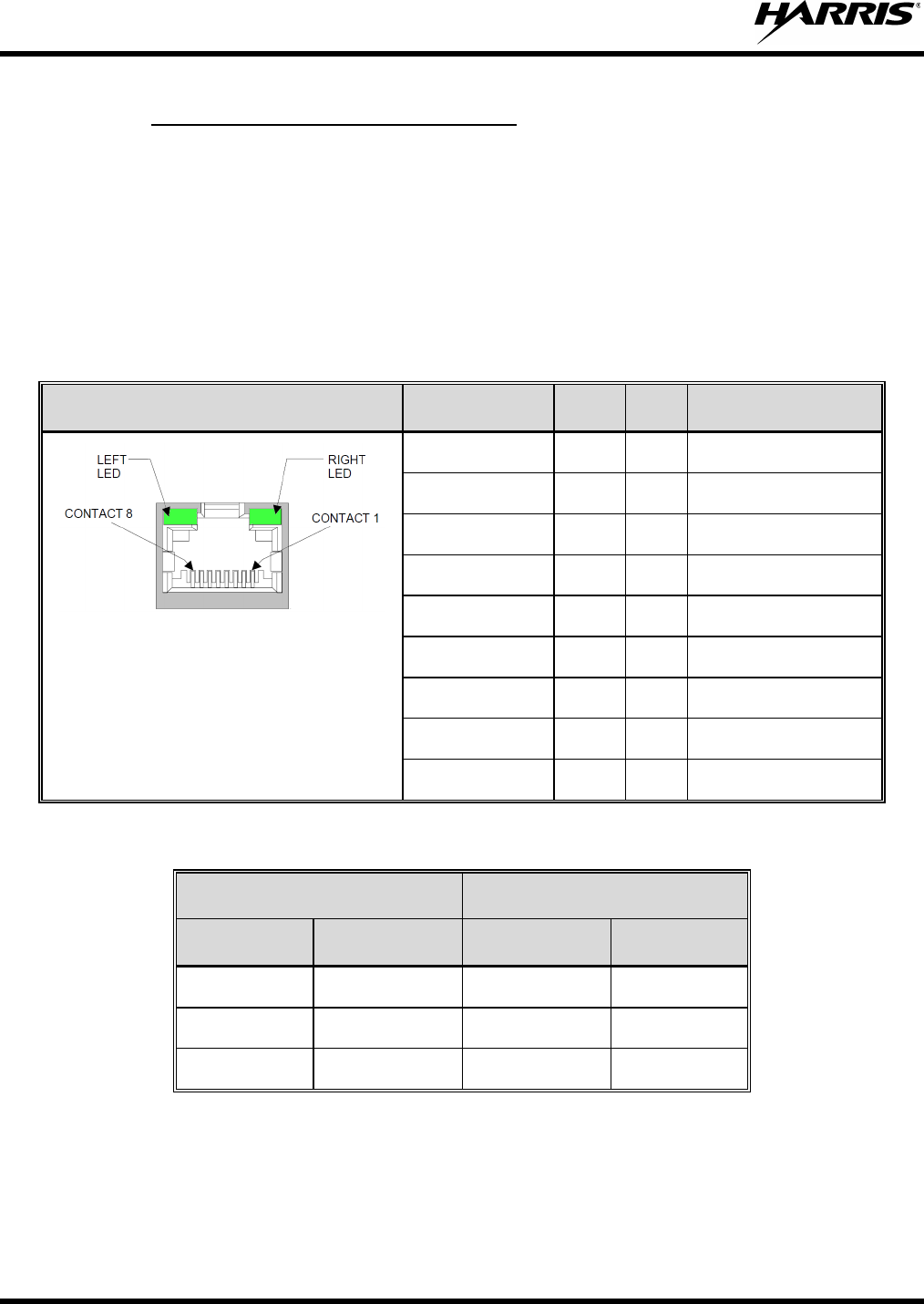
6.5.3 Ethernet Data Interface Connection
The SG5300 Ethernet interface is used for connecting to an RTU. The unit’s Ethernet Interface meets the
following requirements:
• Connector Type: RJ-45 Receptacle
• Electrical Protocol: 10/100Base-T
• Data Rate: 10/100 Mbps
• Data Format: Ethernet IEEE 802.3
Table 6-1: Ethernet Interface Signals
Signal Name Dir Pin Primary Function
TX+ Out 1 Transmit Data +
TX- Out 2 Transmit Data –
RX+ In 3 Receive Data +
RX- In 6 Receive Data –
Not Used 4 Terminated
Not Used 5 Terminated
Not Used 7 Terminated
Not Used 8 Terminated
SHIELD Chassis Ground
Table 6-2: Ethernet LEDs
Link LED (Left Side) Activity LED (Right Side)
Color Meaning Color Meaning
Off No Link Off No Activity
Amber 10 Mbps Amber Half-Duplex
Green 100 Mbps Green Full-Duplex
MM-018623-001
25
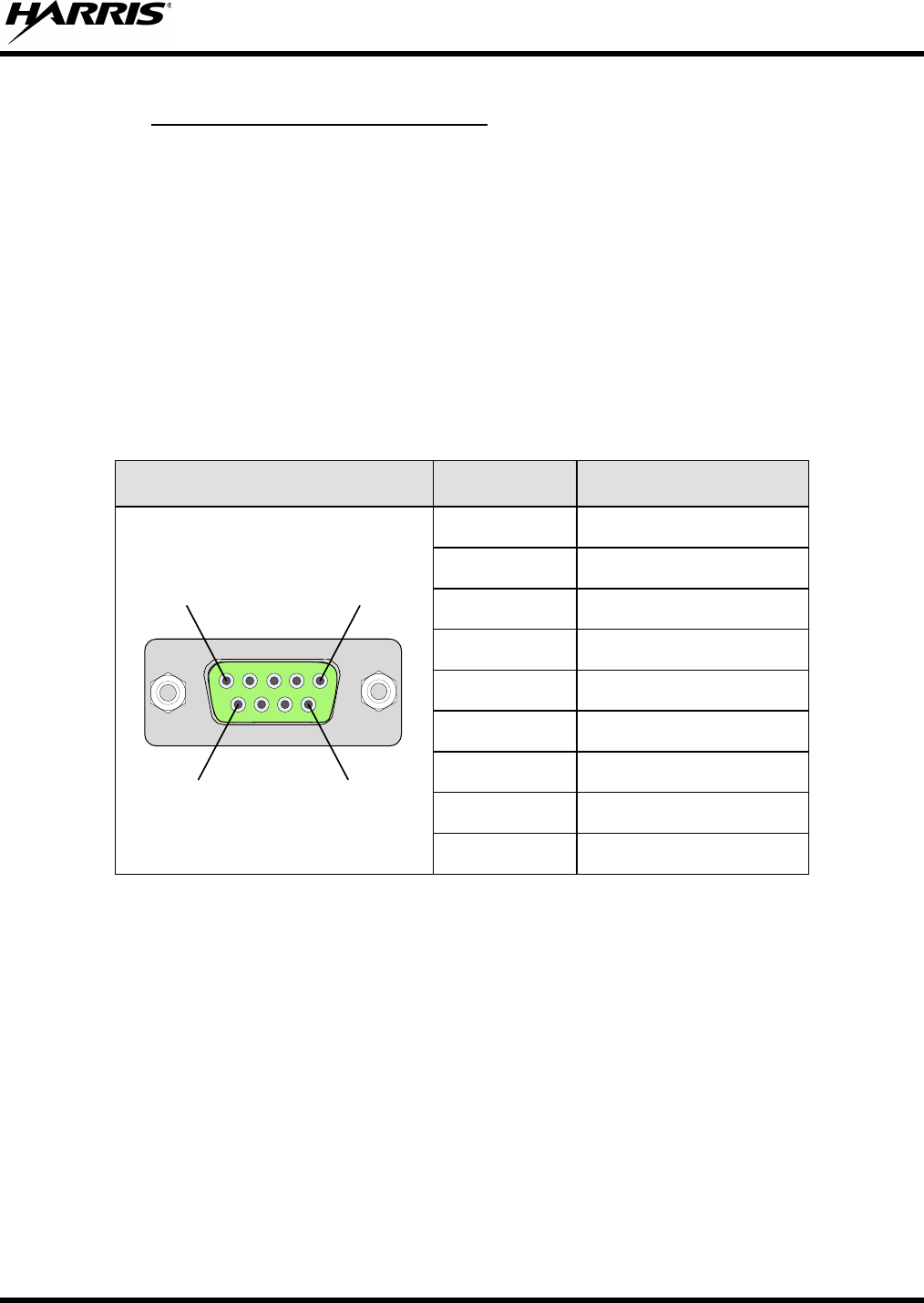
6.5.4 Serial Data Interface Connection
The SG5300 serial interface is used for Serial Line Internet Protocol (SLIP) or Point to Point Protocol
(PPP) data as well as for unit configuration and maintenance support. The serial interface can be
configured to operate as a full duplex DCE EIA/TIA-232 port and meets the following requirements:
• Connector Type: DB-9F Receptacle
• Mating Part Number: DEMM9 Plug
• Electrical Protocol: EIA/TIA-232 Full Duplex
• Data Rate: 9.6 kbps for 900 MHz, 19.2 kbps for 800 MHz
• Data Format: 8 bits/character, No Parity, 1 stop bit
Table 6-3: Serial Interface Signals
Pin Number Signal Name
1
9 6
5
1
5
69
1 Not Connected (NC)
2 Receive Data (RD)
3 Transmit Data (TD)
4 Not Connected (NC)
5 Signal Ground (GND)
6 Not Connected (NC)
7 Request-To-Send (RTS)
8 Clear-To-Send (CTS)
9 Not Connected (NC)
6.6 ANTENNA INSTALLATION
Screw the antenna or antenna cable onto the antenna connector on the top of the SG5300 by turning it
clockwise into the TNC female connector.
1. Connect the antenna feedline (if antenna is not connected directly to the SG5300) between the
antenna and the SG5300 antenna connector.
2. Install surge protectors as required.
6.7 SURGE PROTECTION
When installing an SG5300, you should always install external surge protectors to protect the unit from
lightning or transient damage. Table 6-4 lists surge protectors that have been tested and are available
from Harris.

MM-018623-001
26
Table 6-4: Surge Protection Options
PART NUMBER DESCRIPTION
PT-016508-002 RF Surge Protector, Coax, TNC.
PT-016508-003 Cat5e, RJ-45, Data Port Surge Protector.
PT-016508-005 Surge Protector, DC, Wire, 54 Vdc.
MM-018623-001
27
7 CONFIGURATION
Configuration of the SG5300 is performed with an external computer attached to the DB9 serial port.
Your Network Administrator should configure the SG5300. Changes to the configuration, if required, can
also be made over-the-air if this option has been purchased.
There are three primary considerations when setting up an SG5300. These include configuration and
software loading of either the RF Radio or the Ethernet port.
7.1 EQUIPMENT REQUIRED
Service PC
7.2 CONFIGURING THE RF RADIO
To configure the SG5300 RF Radio unit through a serial connection between a console terminal or PC
and the SG5300’s Serial port:
1. Connect a console terminal or PC running a terminal emulation program (i.e., HyperTerminal) to your
unit’s serial port. The default serial port settings are 19200 baud, 8 bits, no parity, 1-stop bit, no
flow control.
2. Toggle the SG5300’s Configuration Switch from and back to the Serial position. This will reset and
re-boot the RF-Radio which results in a software version banner being sent to the terminal display.
NOTE
If the banner is not output, it maybe necessary to enter the off-line escape commands into
the terminal (i.e., +++ or ***).
3. Enter the following user/system specific configuration setting commands into the SG5300:
NOTE
The SG5300 RF Radio responds with an OK message after each accepted command entry.
MM-018623-001
28
Commands: Description:
at@ar1 Auto Reg where 1=enable, 0=disable.
at\u xxx.xxx.xxx.xxx Service IP Address (xxx.xxx.xxx.xxx).
at\p x Service Port number.
at\s yyy.yyy.yyy.yyy Radio IP Address (yyy.yyy.yyy.yyy).
at\b zzz.zzz.zzz.zzz Broadcast IP Address (zzz.zzz.zzz.zzz).
at@c x,x,x,x Loads Band, Chan#1, Chan#2, RF Protocol.
Where:
Band = 7 (900 MHz) or 8 (800 MHz)
Chan#1 = 0 to 830 (at@c? lists channels)
Chan#2 = 0 (N/A)
RF Protocol = 3 (OTP, 2-slot) or 4 (OTP 4-slot)
at@h x,x,x,x Selects home site, Chan#1, Chan#2, RF
Protocol. (Same parameters as at@c)
at@vreg 0 Enables (1) or disables (0) voice registration.
at@mdp_type x Configures serial port.
0 - Sets the data type for the serial connection to
SLIP.
1 - Sets the serial connection to PPP so the radio
will look for PPP packets from the host.
4. Enter the atz command to reboot the SG5300 RF Radio.
In a few moments the software version banner appears along with the RF radio’s network registration
and connection information.
NOTE
Configuration and wireless network connectivity is verified from the output registration
and connection information.
5. Toggle the SG5300’s Configuration Switch into either the Serial or Ethernet position, as required for
normal operation.
MM-018623-001
29
7.3 CONFIGURING THE ETHERNET PORT
To configure the SG5300 Ethernet port through a serial connection between a console terminal or PC and
the SG5300’s Serial port:
1. Connect a console terminal or PC running a terminal emulation program (i.e. HyperTerminal) to your
unit’s serial port. The default serial port settings are 9600 baud, 8 bits, no parity, 1-stop bit, no-
flow control.
2. Toggle the SG5300’s Configuration Switch from and to the Config-Ethernet position. Within three
(3) seconds of setting the switch, enter three lowercase x characters (xxx).
NOTE
The easiest way to enter Setup Mode is to hold down the x key at the terminal (or
emulation) while switching the unit into Config-Ethernet. You must do this within three
seconds of setting the SG5300’s Configuration Switch into the Config-Ethernet
position.
The terminal should display a firmware version banner similar to the following example:
*** SLIP Server ***
MAC address xxxxxxxxxxxx
Software version V6.5.SLIP (090507) CPK6500_XPTEX
Press Enter for Setup Mode
3. Within 5 seconds, press the Enter key to enter the Ethernet Setup Mode.
The terminal should display the current configuration settings followed by the Change Setup menu:
Change Setup:
0 Server configuration
1 Channel 1 configuration
5 Expert
6 Security
7 factory defaults
8 exit without save
9 save and exit Your choice ?
4. From the Change Setup menu, enter 0 for Server configuration after the “Your choice ?” and press
the Enter key.
5. Set the entry fields (as shown on the next page) where the IP Address xxx.xxx.xxx.xxx is replaced
with the desired IP Address for the SG5300 Ethernet port.
NOTE
After every entry field, a respective default or previously set value will be displayed within
the parenthesis. If the displayed value is correct, simply press the Enter key.
MM-018623-001
30
IP Address : (0) xxx.(0) xxx.(0) xxx.(0) xxx
Set Gateway IP Address (N) ?
Netmask: Number of Bits for Host Part (0=default) (8)
Change telnet config password (N) ?
6. From the Change Setup menu, enter 1 for Channel 1 configuration after “Your choice ?” and press
the Enter key.
7. Set the entry fields as shown below where the Local Serial IP address xxx.xxx.xxx.xxx is replaced
with the previously set SG5300 Ethernet port IP address and the Peer Serial IP address
yyy.yyy.yyy.yyy is replaced with the previously set SG5300 RF Radio IP address.
NOTE
After every entry field, a respective default or previously set value will be displayed within
the parenthesis. If the displayed value is correct, simply press the Enter key.
Baudrate (19200)
I/F Mode (4C) ?
Flow (00) ?
Enable passive mode (N) ?
Enable bridge mode (N) ?
Local Serial IP address: (255) xxx.(255) xxx.(255) xxx.(255) xxx
Peer Serial IP address: (255) yyy.(255) yyy.(255) yyy.(255) yyy
NAT IP address: (000) .(000) .(000) .(000)
NAT IP address offset: (16) ?
DNS Server IP address: (000) .(000) .(000) .(000)
Allow broadcasts in (Y) ?
Monitor Connection Control (N) ?
SLIP Client Mode (N) ?
8. From the Change Setup menu, enter 9 for Save and exit after “Your choice ?” and press the Enter
key.
9. After all values are stored into nonvolatile memory, the terminal should display the “Parameters
stored ...” message.
10. Toggle the SG5300’s Configuration Switch into either the Serial or the Ethernet position for the
desired normal operation of the SG5300.

MM-018623-001
31
8 SOFTWARE INSTALLATION
This section provides instructions for installing software in the SG5300.
8.1 DOWNLOAD SOFTWARE
8.1.1 Set Server IP Address
1. Connect the SG5300 to the PC serial port.
If working with a DTE device a null modem cable or adapter will be required.
2. Place SG5300 serial interface selector switch in the Config Ethernet position.
3. Connect power to the device being configured while depressing the “x” key (must be lower case).
4. The following message should appear:
*** SLIP Server ***
MAC address 00204AB1EA34
Software version V6.5.SLIP (090507) CPK6500_XPTEX
Press Enter for Setup Mode
5. Press the Enter key to enter Setup Mode.
The following message should appear:
Change Setup:
0 Server configuration
1 Channel 1 configuration
5 Expert
6 Security
7 factory defaults
8 exit without save
9 save and exit Your choice ?
6. Proceed to next section to install software.
8.1.2 Install Software
1. If this is a new install and the device has yet to be configured, enter “7” to load factory defaults.
2. Enter “0” to configure server.
3. When prompted for an IP Address, enter the desired IP address (i.e., 192.168.1.254).
4. When asked to set Gateway IP Address (N): Press the Enter key.
5. When prompted for a Netmask, enter: 8
6. Change telnet config password (N): Press the Enter key.

MM-018623-001
32
7. When the following menu appears:
Change Setup:
0 Server configuration
1 Channel 1 configuration
5 Expert
6 Security
7 factory defaults
8 exit without save
9 save and exit Your choice ?
8. Enter “9” to exit configuration mode and start normal operation.
9. Connect the Ethernet port of the slip converter to the Ethernet port of the PC containing the FTP
server and code for the device being configured.
10. Set the TFTP PC’s IP address to 192.168.1.5.
11. Place the code to be downloaded in the directory C:\Code.
12. Place the serial selector switch in the “Ethernet” position.
13. Open a DOS command prompt window.
14. Enter the following command:
tftp –i (IP Address of SG5300) PUT c:\code\xpteslps6.7.SLIP.0.rom X5
(i.e. tftp –i 192.168.1.254 PUT c:\code\ xpteslps6.7.SLIP.0.rom X5)
15. Wait for the transfer to complete (about 8-10 seconds) and then set the needed IP addresses for the
serial ports and the translation tables.
8.2 CONFIGURATION
8.2.1 Set Server IP Address
1. Connect the SG5300 to the serial port of the PC and place the serial interface selector switch in the
Config Ethernet position.
2. Connect power to the device being configured while depressing the “x” key (must be lower case)
When the following message appears :
*** SLIP Server ***
MAC address 00204AB1EA34
Software version V6.5.SLIP (090507) CPK6500_XPTEX
Press Enter for Setup Mode

MM-018623-001
33
3. Press the Enter key to enter Setup Mode.
The following message appears:
Change Setup:
0 Server configuration
1 Channel 1 configuration
5 Expert
6 Security
7 factory defaults
8 exit without save
9 save and exit Your choice ?
4. Enter “0” followed by the enter key.
5. When prompted for an IP Address: enter the desired IP address of the Ethernet server port (i.e.,
192.168.1.254), placing a period between the octets or press the Enter key to move to the next octet.
6. When asked to set Gateway IP Address (N): Press then Enter key.
7. When prompted for a Netmask, enter the number of bits for Host Part (0): 8
8. When prompted to change the telnet config password (N) ?: Press the Enter key.
9. When the following menu appears:
Change Setup:
0 Server configuration
1 Channel 1 configuration
5 Expert
6 Security
7 factory defaults
8 exit without save
9 save and exit Your choice ?
10. If this was the last item to configure then enter “9” followed by the Enter key.
8.2.2 Serial Channel and Network configuration
NOTE
Both the serial converter and the SG5300 have the capability to perform PAT/NAT
translations. Before starting a configuration the user should have a good
understanding of what device(s) are going to be connected to the Ethernet port. The
mapping contained in the static table is a very important piece of the configuration.
1. From the main menu, enter “1” followed by the Enter key.
2. When prompted for the “Baudrate (19200)”: Enter 19200 or press the Enter key.
3. When prompted for the “I/F Mode (4C) ?”: Press the Enter key.

MM-018623-001
34
4. When prompted for the “Flow (00) ?”: Press the Enter key.
5. When prompted for to “Enable passive mode (N) ?”: Press the Enter key.
6. When prompted for the “Enable bridge mode (N) ?”: Press the Enter key.
7. When prompted for the “Local Serial IP address”: Enter the desired IP address of the local serial port
(i.e., 10.248.15.85 ), placing a period between the octets or press the Enter key to move to the next
octet.
8. When prompted for the “Peer Serial IP address”: Enter the IP address assigned to the radio serial port
(i.e., 10.248.15.86 ), placing a period between the octets or press the Enter key to move to the next
octet.
9. When prompted for the “NAT IP address (000.000.000.000)”: Leave set to 000.000.000.000 placing
a period between the octets or press the Enter key to move to the next octet.
10. When prompted for the “NAT IP address offset: (16) ?”: Press the Enter key.
11. When prompted for the “DNS Server IP address: address (000.000.000.000)”: Leave set to
000.000.000.000, placing a period between the octets or press the Enter key to move to the next
octet.
12. When prompted for the “Allow broadcasts in (N) ?”: Press the Enter key.
13. When prompted for the “Monitor Connection Control (N) ?”: Press the Enter key.
14. When prompted for the “SLIP Client Mode (N) ?”: Press the Enter key.
Static Map Table
PROTO [Cloud Socket] [Ethernet Socket]
01: ICM 010.000.000.001:00000 <-> 192.168.001.001:00000
02: UDP 010.000.000.001:00000 <-> 192.168.001.001:00000
03: --- 000.000.000.000:00000 <-> 000.000.000.000:00000
04: --- 000.000.000.000:00000 <-> 000.000.000.000:00000
05: --- 000.000.000.000:00000 <-> 000.000.000.000:00000
06: --- 000.000.000.000:00000 <-> 000.000.000.000:00000
07: --- 000.000.000.000:00000 <-> 000.000.000.000:00000
08: --- 000.000.000.000:00000 <-> 000.000.000.000:00000
09: --- 000.000.000.000:00000 <-> 000.000.000.000:00000
10: --- 000.000.000.000:00000 <-> 000.000.000.000:00000
11: --- 000.000.000.000:00000 <-> 000.000.000.000:00000
12: --- 000.000.000.000:00000 <-> 000.000.000.000:00000
13: --- 000.000.000.000:00000 <-> 000.000.000.000:00000
14: --- 000.000.000.000:00000 <-> 000.000.000.000:00000
15. When prompted for to “Change Map Table? (N) ?”: Enter Y and press the Enter key.
16. When prompted for to “Clear Map Table? (N) ?”: Press the Enter key.
17. When prompted for to “Edit entry # (0 to exit): (0) ?: Enter 1

MM-018623-001
35
18. When prompted for the “Map Cloud TCP, UDP or ICMP to Ethernet IP & Port T(CP) or U(DP) or
(I)CMP”: Enter:
• I for ICMP traffic
• U for UDP traffic
• T for TCP traffic
19. When prompted for the “Cloud Port #: (0) ?”: Enter the port number that was assigned at the source
of the message i.e., (telnet port 23, HTTP port 80).
20. When prompted for the”Tto Port #: (0) ?”: Enter the port number that the destinstion application will
want to see.
If it is the same number assigned at the source of the message (i.e. telnet port 23, HTTP port 80),
enter 0 for the cloud port and to port numbers. When both the cloud and two port numbers are set to
zero no port translation takes place.
21. When prompted for the “At IP address”: Enter the destination IP address, (where you want the data
sent to on the Ethernet port network.), placing a period between the octets or press the Enter key to
move to the next octet.
22. When prompted for the “Edit entry # (0 to exit): (1) ?”: Enter 0 if all entries have been completed or
the next table position to be configured.
23. If 0 was entered, you will be given the current static map table and asked if you wish to make
changes. Review the entries, if correct enter “N;” otherwise, enter “Y” and make any needed
corrections.
Static Map Table
PROTO [Cloud Socket] [Ethernet Socket]
01: ICM 010.000.000.001:00000 <-> 192.168.001.001:00000
02: UDP 010.000.000.001:00000 <-> 192.168.001.001:00000
03: --- 000.000.000.000:00000 <-> 000.000.000.000:00000
04: --- 000.000.000.000:00000 <-> 000.000.000.000:00000
05: --- 000.000.000.000:00000 <-> 000.000.000.000:00000
06: --- 000.000.000.000:00000 <-> 000.000.000.000:00000
07: --- 000.000.000.000:00000 <-> 000.000.000.000:00000
08: --- 000.000.000.000:00000 <-> 000.000.000.000:00000
09: --- 000.000.000.000:00000 <-> 000.000.000.000:00000
10: --- 000.000.000.000:00000 <-> 000.000.000.000:00000
11: --- 000.000.000.000:00000 <-> 000.000.000.000:00000
12: --- 000.000.000.000:00000 <-> 000.000.000.000:00000
13: --- 000.000.000.000:00000 <-> 000.000.000.000:00000
14: --- 000.000.000.000:00000 <-> 000.000.000.000:00000
Change Map Table? (N) ?
24. When the following information is displayed select menu item “9” followed by the Enter key to save
changes and exit.
*** basic parameters
Hardware: Ethernet TPI

MM-018623-001
36
IP addr 192.168.1.254, no gateway set,netmask 255.255.255.0
*** Security
SNMP is enabled
SNMP Community Name: public
Telnet Setup is enabled
TFTP Download is enabled
Port 77FEh is enabled
Web Server is enabled
Web Setup is enabled
ECHO is disabled
Enhanced Password is disabled
***************** Channel 1 *****************
Baudrate 19200, I/F Mode 4C, Flow 00
CPU performance : Standard
Local Serial IP address 10.0.0.2
Peer Serial IP address 10.0.0.1
NAT IP address 0.0.0.0
NAT IP address offset 16
DNS Server IP address 0.0.0.0
Passive Mode: disabled
Bridge Mode: disabled
Allow broadcasts: disabled
Monitor Connection Control: disabled
SLIP Client Mode: disabled
Static Map Table
PROTO [Cloud Socket] [Ethernet Socket]
01: ICM 010.000.000.001:00000 <-> 192.168.001.001:00000
02: UDP 010.000.000.001:00000 <-> 192.168.001.001:00000
03: --- 000.000.000.000:00000 <-> 000.000.000.000:00000
04: --- 000.000.000.000:00000 <-> 000.000.000.000:00000
05: --- 000.000.000.000:00000 <-> 000.000.000.000:00000
06: --- 000.000.000.000:00000 <-> 000.000.000.000:00000
07: --- 000.000.000.000:00000 <-> 000.000.000.000:00000
08: --- 000.000.000.000:00000 <-> 000.000.000.000:00000
09: --- 000.000.000.000:00000 <-> 000.000.000.000:00000
10: --- 000.000.000.000:00000 <-> 000.000.000.000:00000
11: --- 000.000.000.000:00000 <-> 000.000.000.000:00000
12: --- 000.000.000.000:00000 <-> 000.000.000.000:00000
13: --- 000.000.000.000:00000 <-> 000.000.000.000:00000
14: --- 000.000.000.000:00000 <-> 000.000.000.000:00000
*** Expert
CPU performance: Regular
Monitor Mode @ bootup : enabled
MTU Size: 1400
Alternate MAC: disabled
Ethernet connection type: auto-negotiate

MM-018623-001
37
Change Setup:
0 Server configuration
1 Channel 1 configuration
5 Expert
6 Security
7 factory defaults
8 exit without save
9 save and exit Your choice ?
8.2.3 Load Factory Defaults
1. When the following menu appears, enter “7” followed by the Enter key.
Change Setup:
0 Server configuration
1 Channel 1 configuration
5 Expert
6 Security
7 factory defaults
8 exit without save
9 save and exit Your choice ?
2. After selecting factory defaults, select menu item “9” followed by the Enter key to exit and save
changes.
8.3 IMPLEMENTATION
1. Once the new slip code is loaded you will receive a message similar to the following when you
connect to the SG5300:
*** SLIP Server ***
MAC address 00204ACDBE06
Software version V6.7.SLIP.0 (101220) CPK6702_XPTEX
Press Enter for Setup Mode
*** basic parameters
Hardware: Ethernet TPI
IP addr 10.248.15.109, no gateway set,netmask 255.255.255.0
*** Security
SNMP is enabled
SNMP Community Name: public
Telnet Setup is enabled
TFTP Download is enabled
Port 77FEh is enabled
Web Server is enabled
Web Setup is enabled
ECHO is disabled
Enhanced Password is disabled

MM-018623-001
38
***************** Channel 1 *****************
Baudrate 9600, I/F Mode 4C, Flow 00
CPU performance : Standard
Local Serial IP address 255.255.255.255
Peer Serial IP address 255.255.255.255
NAT IP address 255.255.255.255
DNS Server IP address 255.255.255.255
Passive Mode: enabled
Bridge Mode: enabled
Allow broadcasts: enabled
Monitor Connection Control: enabled
SLIP Client Mode: enabled
Static Map Table
PROTO [Cloud Socket] [Ethernet Socket]
01: --- 000.000.000.000:00000 <-> 000.000.000.000:00000
02: --- 000.000.000.000:00000 <-> 000.000.000.000:00000
03: --- 000.000.000.000:00000 <-> 000.000.000.000:00000
04: --- 000.000.000.000:00000 <-> 000.000.000.000:00000
05: --- 000.000.000.000:00000 <-> 000.000.000.000:00000
06: --- 000.000.000.000:00000 <-> 000.000.000.000:00000
07: --- 000.000.000.000:00000 <-> 000.000.000.000:00000
08: --- 000.000.000.000:00000 <-> 000.000.000.000:00000
09: --- 000.000.000.000:00000 <-> 000.000.000.000:00000
10: --- 000.000.000.000:00000 <-> 000.000.000.000:00000
11: --- 000.000.000.000:00000 <-> 000.000.000.000:00000
12: --- 000.000.000.000:00000 <-> 000.000.000.000:00000
13: --- 000.000.000.000:00000 <-> 000.000.000.000:00000
14: --- 000.000.000.000:00000 <-> 000.000.000.000:00000
*** Expert
CPU performance: Regular
Monitor Mode @ bootup : enabled
MTU Size: 1400
Alternate MAC: disabled
Ethernet connection type: auto-negotiate
Change Setup:
0 Server configuration
1 Channel 1 configuration
5 Expert
6 Security
7 factory defaults
8 exit without save
9 save and exit Your choice ?

MM-018623-001
39
2. If this is to be a new installation, select menu option “7” followed by menu option “9.”
If you selected menu option “7,” you will get the following configuration the next time you connect
to the SG5300:
• An address for the server port has been set to 192.168.1.254 with a subnet mask of
255.255.255.0.
• The serial ports have been assigned along with basic static table entries.
*** basic parameters
Hardware: Ethernet TPI
IP addr 192.168.1.254, no gateway set,netmask 255.255.255.0
*** Security
SNMP is enabled
SNMP Community Name: public
Telnet Setup is enabled
TFTP Download is enabled
Port 77FEh is enabled
Web Server is enabled
Web Setup is enabled
ECHO is disabled
Enhanced Password is disabled
***************** Channel 1 *****************
Baudrate 19200, I/F Mode 4C, Flow 00
CPU performance : Standard
Local Serial IP address 10.0.0.2
Peer Serial IP address 10.0.0.1
NAT IP address 0.0.0.0
NAT IP address offset 16
DNS Server IP address 0.0.0.0
Passive Mode: disabled
Bridge Mode: disabled
Allow broadcasts: disabled
Monitor Connection Control: disabled
SLIP Client Mode: disabled
Static Map Table
PROTO [Cloud Socket] [Ethernet Socket]
01: ICM 010.000.000.001:00000 <-> 192.168.001.001:00000
02: UDP 010.000.000.001:00000 <-> 192.168.001.001:00000
03: --- 000.000.000.000:00000 <-> 000.000.000.000:00000
04: --- 000.000.000.000:00000 <-> 000.000.000.000:00000
05: --- 000.000.000.000:00000 <-> 000.000.000.000:00000
06: --- 000.000.000.000:00000 <-> 000.000.000.000:00000
07: --- 000.000.000.000:00000 <-> 000.000.000.000:00000
08: --- 000.000.000.000:00000 <-> 000.000.000.000:00000
09: --- 000.000.000.000:00000 <-> 000.000.000.000:00000
10: --- 000.000.000.000:00000 <-> 000.000.000.000:00000
11: --- 000.000.000.000:00000 <-> 000.000.000.000:00000
MM-018623-001
40
12: --- 000.000.000.000:00000 <-> 000.000.000.000:00000
13: --- 000.000.000.000:00000 <-> 000.000.000.000:00000
14: --- 000.000.000.000:00000 <-> 000.000.000.000:00000
*** Expert
CPU performance: Regular
Monitor Mode @ bootup : enabled
MTU Size: 1400
Alternate MAC: disabled
Ethernet connection type: auto-negotiate
Change Setup:
0 Server configuration
1 Channel 1 configuration
5 Expert
6 Security
7 factory defaults
8 exit without save
9 save and exit Your choice ?
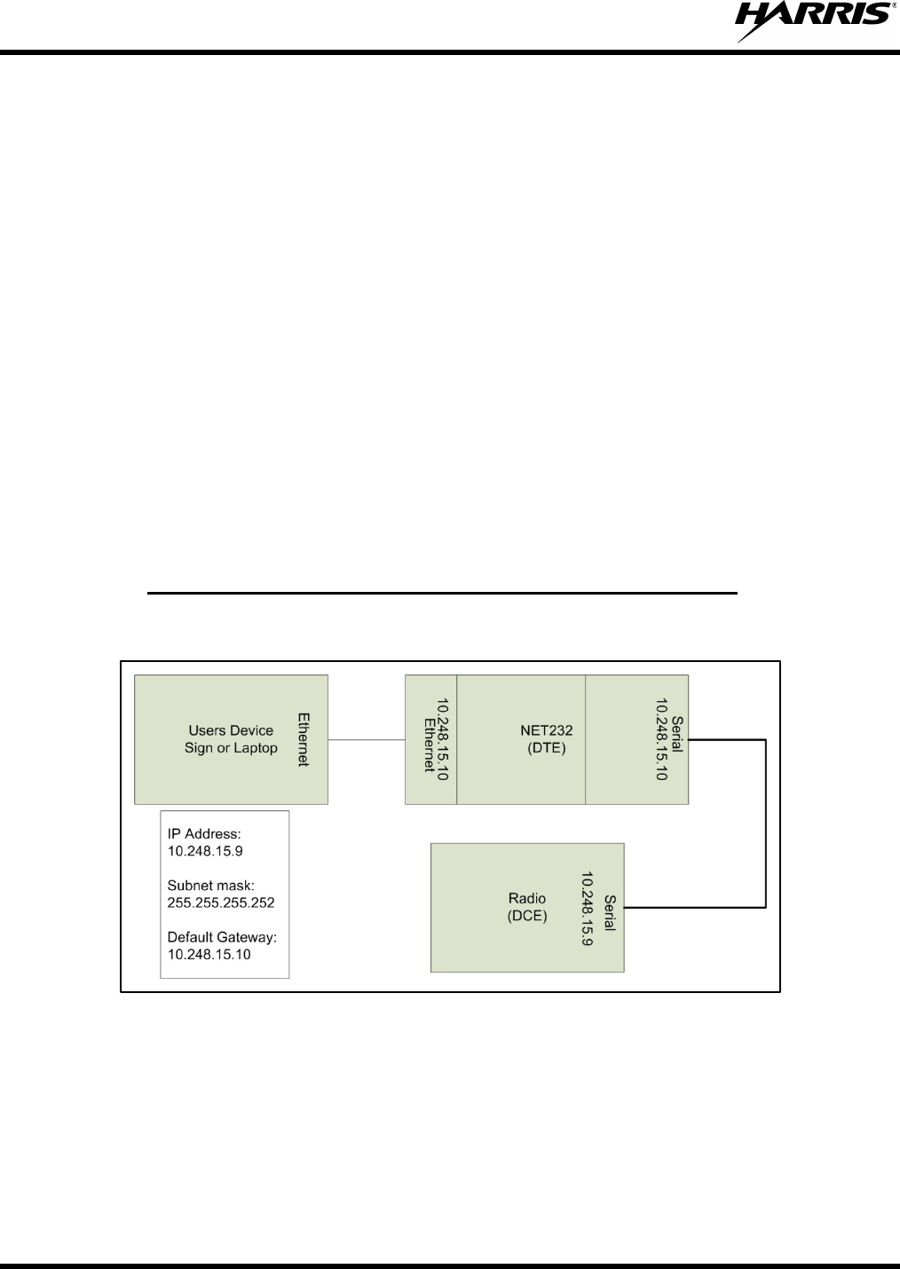
8.3.1 Sample Implementation, SG5300 and One Logical Network
This is a sample implementation for a single device and one (1) logical network.
Figure 8-1: SG5300 and One logical network
For this example you would enter the following configuration:
1. Assign a Server IP Address and net mask (Menu Selection 0).
2. Assign a Serial IP Address (Menu Selection 1).
3. Assign a Peer Serial IP Address (Menu Selection 1).

MM-018623-001
41
4. Assign static entries into the translation table to allow UDP and ICMP traffic (Menu Selection 1 table
entry).
When you have completed your configuration entries, your configuration will look like the following:
*** basic parameters
Hardware: Ethernet TPI
IP addr 10.248.15.10, no gateway set,netmask 255.255.255.0
*** Security
SNMP is enabled
SNMP Community Name: public
Telnet Setup is enabled
TFTP Download is enabled
Port 77FEh is enabled
Web Server is enabled
Web Setup is enabled
ECHO is disabled
Enhanced Password is disabled
***************** Channel 1 *****************
Baudrate 19200, I/F Mode 4C, Flow 00
CPU performance : Standard
Local Serial IP address 10.248.15.10
Peer Serial IP address 10.248.15.9
NAT IP address 0.0.0.0
NAT IP address offset 16
DNS Server IP address 0.0.0.0
Passive Mode: disabled
Bridge Mode: disabled
Allow broadcasts: disabled
Monitor Connection Control: disabled
SLIP Client Mode: disabled
Static Map Table
PROTO [Cloud Socket] [Ethernet Socket]
01: ICM 010.248.015.009:00000 <-> 010.248.015.009:00000 (Sends all ICMP traffic from the
peer serial port to 010.248.015.009 at the Ethernet port)
02: UDP 010.248.015.010:00000 <-> 010.248.015.009:00000 (Sends all UDP traffic from the
peer serial port to 010.248.015.009 at the Ethernet port)
03: --- 000.000.000.000:00000 <-> 000.000.000.000:00000
04: --- 000.000.000.000:00000 <-> 000.000.000.000:00000
05: --- 000.000.000.000:00000 <-> 000.000.000.000:00000
06: --- 000.000.000.000:00000 <-> 000.000.000.000:00000
07: --- 000.000.000.000:00000 <-> 000.000.000.000:00000
08: --- 000.000.000.000:00000 <-> 000.000.000.000:00000
09: --- 000.000.000.000:00000 <-> 000.000.000.000:00000
10: --- 000.000.000.000:00000 <-> 000.000.000.000:00000
11: --- 000.000.000.000:00000 <-> 000.000.000.000:00000
12: --- 000.000.000.000:00000 <-> 000.000.000.000:00000
MM-018623-001
42
13: --- 000.000.000.000:00000 <-> 000.000.000.000:00000
14: --- 000.000.000.000:00000 <-> 000.000.000.000:00000
*** Expert
CPU performance: Regular
Monitor Mode @ bootup : enabled
MTU Size: 1400
Alternate MAC: disabled
Ethernet connection type: auto-negotiate
5. Select menu item “9” to save your configuration and exit.
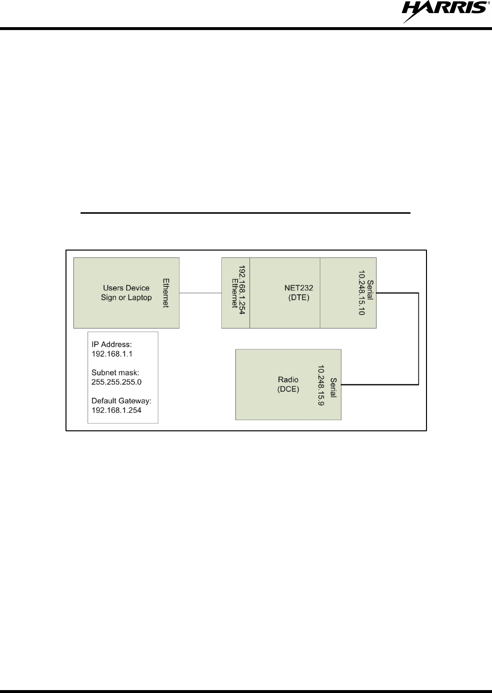
8.3.2 Sample Implementation, SG5300 and Two Logical Networks
This is a sample implementation for a single device and two (2) logical networks.
Figure 8-2: SG5300 and Two Logical Networks
For this example you would enter the following configuration:
1. Assign a Server IP Address and net mask (Menu Selection 0).
2. Assign a Serial IP Address (Menu Selection 1).
3. Assign a Peer Serial IP Address (Menu Selection 1).
4. Assign static entries into the translation table to allow UDP and ICMP traffic (Menu Selection 1 table
entry).
5. When you have completed your configuration entries, your configuration will look like the following:
*** basic parameters
Hardware: Ethernet TPI
IP addr 192.168.1.254, no gateway set,netmask 255.255.255.0

MM-018623-001
43
*** Security
SNMP is enabled
SNMP Community Name: public
Telnet Setup is enabled
TFTP Download is enabled
Port 77FEh is enabled
Web Server is enabled
Web Setup is enabled
ECHO is disabled
Enhanced Password is disabled
***************** Channel 1 *****************
Baudrate 19200, I/F Mode 4C, Flow 00
CPU performance : Standard
Local Serial IP address 10.248.15.10
Peer Serial IP address 10.248.15.9
NAT IP address 0.0.0.0
NAT IP address offset 16
DNS Server IP address 0.0.0.0
Passive Mode: disabled
Bridge Mode: disabled
Allow broadcasts: disabled
Monitor Connection Control: disabled
SLIP Client Mode: disabled
Static Map Table
PROTO [Cloud Socket] [Ethernet Socket]
01: ICM 010.248.015.009:00000 <-> 192.168.001.001:00000 (Sends all ICMP traffic to
192.168.001.001 )
02: UDP 010.248.015.009:00000 <-> 192.168.001.001:00000 (Sends all ICMP traffic to
192.168.001.001 )
03: --- 000.000.000.000:00000 <-> 000.000.000.000:00000
04: --- 000.000.000.000:00000 <-> 000.000.000.000:00000
05: --- 000.000.000.000:00000 <-> 000.000.000.000:00000
06: --- 000.000.000.000:00000 <-> 000.000.000.000:00000
07: --- 000.000.000.000:00000 <-> 000.000.000.000:00000
08: --- 000.000.000.000:00000 <-> 000.000.000.000:00000
09: --- 000.000.000.000:00000 <-> 000.000.000.000:00000
10: --- 000.000.000.000:00000 <-> 000.000.000.000:00000
11: --- 000.000.000.000:00000 <-> 000.000.000.000:00000
12: --- 000.000.000.000:00000 <-> 000.000.000.000:00000
13: --- 000.000.000.000:00000 <-> 000.000.000.000:00000
14: --- 000.000.000.000:00000 <-> 000.000.000.000:00000
*** Expert
CPU performance: Regular
Monitor Mode @ bootup : enabled
MM-018623-001
44
MTU Size: 1400
Alternate MAC: disabled
Ethernet connection type: auto-negotiate
6. Select menu item “9” to save your configuration and exit.
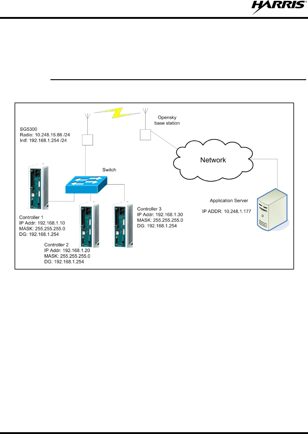
8.3.3 Sample Implementation, SG5300, 2 logical networks, and Multiple Devices
This is a sample implementation for multiple devices and two (2) logical networks.
Figure 8-3: SG5300, Two Logical Networks, and Multiple Devices
In this example, the application server will need to maintain a static table that it associates the 192.x.x.x
network address to a port number. Also assume the ports and IP addresses have been associated in the
following manner:
• 192.168.10 = 10.248.15.86 port 5010
• 192.168.20 = 10.248.15.86 port 5020
• 192.168.30 = 10.248.15.86 port 5030
For this example you would enter the following configuration:
1. Assign a Server IP Address and net mask (Menu Selection 0).
2. Assign a Serial IP Address (Menu Selection 1).
3. Assign a Peer Serial IP Address (Menu Selection 1).

MM-018623-001
45
4. Assign static entries into the translation table to allow UDP and ICMP traffic (Menu Selection 1 table
entry).
5. When you have completed your configuration entries, you configuration will look like the following
data:
*** basic parameters
Hardware: Ethernet TPI
IP addr 192.168.1.254, no gateway set,netmask 255.255.255.0
*** Security
SNMP is enabled
SNMP Community Name: public
Telnet Setup is enabled
TFTP Download is enabled
Port 77FEh is enabled
Web Server is enabled
Web Setup is enabled
ECHO is disabled
Enhanced Password is disabled
***************** Channel 1 *****************
Baudrate 19200, I/F Mode 4C, Flow 00
CPU performance : Standard
Local Serial IP address 10.248.15.85
Peer Serial IP address 10.248.15.86
NAT IP address 0.0.0.0
NAT IP address offset 16
DNS Server IP address 0.0.0.0
Passive Mode: disabled
Bridge Mode: disabled
Allow broadcasts: disabled
Monitor Connection Control: disabled
SLIP Client Mode: disabled
Static Map Table
PROTO [Cloud Socket] [Ethernet Socket]
01: ICM 010.248.015.086:00000 <-> 192.168.001.010:00000 (Sends all ICMP traffic to
192.168.001.010 )
02: UDP 010.248.015.086:05010 <-> 192.168.001.010:00000 (Sends all ICMP traffic to
192.168.001.010 )
03: UDP 010.248.015.086:05020 <-> 192.168.001.020:00000 (Sends all ICMP traffic to
192.168.001.020 )
04: UDP 010.248.015.086:05030 <-> 192.168.001.030:00000 (Sends all ICMP traffic to
192.168.001.030 )
05: --- 000.000.000.000:00000 <-> 000.000.000.000:00000
06: --- 000.000.000.000:00000 <-> 000.000.000.000:00000
07: --- 000.000.000.000:00000 <-> 000.000.000.000:00000
08: --- 000.000.000.000:00000 <-> 000.000.000.000:00000
09: --- 000.000.000.000:00000 <-> 000.000.000.000:00000

MM-018623-001
46
10: --- 000.000.000.000:00000 <-> 000.000.000.000:00000
11: --- 000.000.000.000:00000 <-> 000.000.000.000:00000
12: --- 000.000.000.000:00000 <-> 000.000.000.000:00000
13: --- 000.000.000.000:00000 <-> 000.000.000.000:00000
14: --- 000.000.000.000:00000 <-> 000.000.000.000:00000
*** Expert
CPU performance: Regular
Monitor Mode @ bootup : enabled
MTU Size: 1400
Alternate MAC: disabled
Ethernet connection type: auto-negotiate
6. Select menu item “9” to save your configuration and exit.

MM-018623-001
47
9 TROUBLESHOOTING AND SERVICING
There are no user serviceable components within the SG5300 assembly. This assembly
contains ESD sensitive components and should only be serviced by Harri
s qualified
personnel.
9.1 TROUBLESHOOTING
If a unit is suspected to be faulty or need service and repair, perform the following checks:
• Visually inspect the installation for obvious defects such as worn, weathered, or frayed cabling.
• Verify that the unit is receiving sufficient voltage and current to the power input connector.
• Replace any defective antenna or power source components as required, and return any inoperable
SG5300s to Harris for repairs.
9.2 SERVICING
The SG5300 is not a field repairable unit. If a unit is suspected to need servicing or re-alignment, then the
unit should be removed from service and returned to Harris for repairs. Periodic checks of frequency and
modulation bandwidth should be performed during routine preventative maintenance checks.
Troubleshooting the SG5300 is not difficult, but it requires a logical approach.
It is good practice to start by checking the simple things. For proper operation, the SG5300 must meet the
following basic requirements:
• Proper and stable primary power. Remove power to reset the unit.
• Ensure all connections (RF, data, and power) and secure.
• Ensure the antenna system (antenna and lightning protection) are properly connected and in
working order.
• Ensure the SG5300 is properly configured.
• Ensure you are using the correct interface between the SG5300 and the connected data equipment
(correct cable wiring, proper data format, timing, etc.).
• The LED status indicators are an important troubleshooting tool and should be checked whenever
a problem is suspected. Table 4-1 describes the function of each status LED.
NOTE
There are no field repairable components in the SG5300 RF Radio unit. If you suspect the
SG5300 is defective, replace it with a known good unit and return the defective assembly to
Harris for repair.
If troubleshooting assistance is required, contact a qualified service technician or Harris Technical
Assistance Center (see Section 10).

MM-018623-001
48
10 CUSTOMER SERVICE
10.1 TECHNICAL ASSISTANCE
The Technical Assistance Center's (TAC) resources are available to help with overall system operation,
maintenance, upgrades, and product support. TAC is the point of contact when answers are needed to
technical questions.
Product specialists, with detailed knowledge of product operation, maintenance, and repair provide
technical support via a toll-free (in North America) telephone number. Support is also available through
mail, fax, and e-mail.
For more information about technical assistance services, contact your sales representative, or contact the
Technical Assistance Center directly at:
North America: 1-800-528-7711
International: 1-434-385-2400
Fax: 1-434-455-6712
E-mail: PSPC_tac@harris.com
10.2 CUSTOMER CARE
If any part of the system equipment is damaged on arrival, contact the shipper to conduct an inspection
and prepare a damage report. Save the shipping container and all packing materials until the inspection
and the damage report are completed. In addition, contact the Customer Care center to make
arrangements for replacement equipment. Do not return any part of the shipment until you receive
detailed instructions from a Harris representative.
Contact the Customer Care center at http://www.pspc.harris.com/CustomerService or:
North America:
Phone Number: 1-800-368-3277
Fax Number: 1-321-409-4393
E-mail: PSPC_CustomerFocus@harris.com
International:
Phone Number: 1-434-455-6403
Fax Number: 1-321-409-4394
E-mail: PSPC_InternationalCustomerFocus@harris.com

MM-018623-001
49
11 SPECIFICATIONS
11.1 GENERAL SPECIFICATIONS
Model Number:
SG5300-800 (RU-019026-800)
SG5300-900 (RU-019026-900)
Physical Characteristics:
Electrical Power: +9 to +57 Vdc
Power Consumption: 9.6 Watt Transmit
2.5 Watt Receive
<3 Watt Average Power at 95/5
Size (H x W x D): 1.5 × 3.9 × 7.8 in
(3.9 × 10.0 × 19.8 cm)
Weight: 1.6 lbs (0.7 kg)
(less mounting hardware)
Environmental Specifications:
Operating Temperature: -22 to +140°F (-30 to +60°C)
Relative Humidity: 95% @ 122°F (+50°C)
Altitude: 15000 ft
(4572 m)
Color (case) Black & Metallic
System Interfaces (Ethernet or Serial):
Ethernet - The SG5300 Ethernet
interface is used for connecting to an
RTU.
• Connector Type: RJ45
• Electrical Protocol: 10/100 BaseT
• Data Format: Ethernet IEEE 802.3
Serial - The SG5300 serial interface is
used for data (SLIP/PPP) as well as for
maintenance support. The serial interface
is configurable to operate as a full duplex
DCE EIA/TIA-232 port.
• Connector Type: 9-pin D Receptacle
• Electrical Protocol: EIA/TIA-232 Full Duplex
• Data Format: 8 bits/character, 1 start bit, 1 stop
bit

MM-018623-001
50
11.2 TRANSMITTER SPECIFICATIONS
Typical performance specifications 800 MHz 900 MHz
Frequency Range (MHz): 806-809 / 809-824 896-901 / 935-940
Rated RF Power Trunked (W): 0.5-3 0.5-3
Frequency Stability
(-30 to +60°C; +25°C Ref) (ppm):
±1.5 / ±2.5
±1.5
Modulation Deviation (kHz): ±3.75 / ±4.0 ±1.8
11.3 RECEIVER SPECIFICATIONS
Typical performance specifications 800 MHz 900 MHz
Frequency Range (MHz): 851-870 935-940
Frequency Separation (MHz): Full bandwidth Full bandwidth
Channel Spacing (kHz): 25/NPSPAC 12.5
Frequency Stability
(-30 to +60°C; +25 Ref) (ppm):
±1.5
±1.5
11.4 DIGITAL OPERATION
Data Rate (kbps): 19.2 for 800 MHz, 9.6 for 900 MHz
Modulation: 4-Level GFSK; M4FM

MM-018623-001
51
12 WARRANTY
Please register this product within 10 days of purchase. Registration validates the warranty coverage, and enables
Harris to contact you in case of any safety notifications issued for this product.
Registration can be made on-line at http://www.pspc.harris.com/Service/WarrantySupport.asp.
A. Harris Corporation, a Delaware Corporation, through its RF Communications Division (hereinafter "Seller") warrants to the
original purchaser for use (hereinafter "Buyer") that Equipment manufactured by or for the Seller shall be free from defects
in material and workmanship, and shall conform to its published specifications. With respect to all non-Seller Equipment,
Seller gives no warranty, and only the warranty, if any, given by the manufacturer shall apply. Rechargeable batteries are
excluded from this warranty but are warranted under a separate Rechargeable Battery Warranty (ECR-7048).
B. Seller’s obligations set forth in Paragraph C below shall apply only to failures to meet the above warranties occurring
within the following periods of time from date of sale to the Buyer and are conditioned on Buyer’s giving written notice to
Seller within thirty (30) days of such occurrence:
1. for fuses and non-rechargeable batteries, operable on arrival only.
2. for parts and accessories (except as noted in B.1), ninety (90) days.
3. for P7300, P7200, P7100IP, P5400, P5300, P5200, P5100, P3300, M7300, M7200
(including V-TAC), M7100IP, M5300, M3300, and SG5300s, two (2) years, effective 10/01/2007.
4. for Unity® XG-100P, three (3) years.
5. for all other equipment of Seller’s manufacture, one (1) year.
C. If any Equipment fails to meet the foregoing warranties, Seller shall correct the failure at its option (i) by repairing any
defective or damaged part or parts thereof, (ii) by making available at Seller’s factory any necessary repaired or
replacement parts, or (iii) by replacing the failed Equipment with equivalent new or refurbished Equipment. Any repaired
or replacement part furnished hereunder shall be warranted for the remainder of the warranty period of the Equipment in
which it is installed. Where such failure cannot be corrected by Seller’s reasonable efforts, the parties will negotiate an
equitable adjustment in price. Labor to perform warranty service will be provided at no charge during the warranty period
only for the Equipment covered under Paragraph B.3 and B.4. To be eligible for no-charge labor, service must be
performed at Seller’s factory, by an Authorized Service Center (ASC) or other Servicer approved for these purposes either
at its place of business during normal business hours, for mobile or personal equipment, or at the Buyer’s location, for
fixed location equipment. Service on fixed location equipment more than thirty (30) miles from the Service Center or other
approved Servicer’s place of business will include a charge for transportation.
D. Seller’s obligations under Paragraph C shall not apply to any Equipment, or part thereof, which (i) has been modified or
otherwise altered other than pursuant to Seller’s written instructions or written approval or, (ii) is normally consumed in
operation or, (iii) has a normal life inherently shorter than the warranty periods specified in Paragraph B, or (iv) is not
properly stored, installed, used, maintained or repaired, or, (v) has been subjected to any other kind of misuse or
detrimental exposure, or has been involved in an accident.
E. The preceding paragraphs set forth the exclusive remedies for claims based upon defects in or nonconformity of the
Equipment, whether the claim is in contract, warranty, tort (including negligence), strict liability or otherwise, and however
instituted. Upon the expiration of the warranty period, all such liability shall terminate. The foregoing warranties are
exclusive and in lieu of all other warranties, whether oral, written, expressed, implied or statutory. NO IMPLIED OR
STATUTORY WARRANTIES OF MERCHANTABILITY OR FITNESS FOR PARTICULAR PURPOSE SHALL APPLY. IN
NO EVENT SHALL THE SELLER BE LIABLE FOR ANY INCIDENTAL, CONSEQUENTIAL, SPECIAL, INDIRECT OR
EXEMPLARY DAMAGES.
This warranty applies only within the United States.
Harris Corporation Harris Corporation
RF Communications Division RF Communications Division
221 Jefferson Ridge Parkway 1680 University Avenue
Lynchburg, VA 24501 Rochester, NY 14610
1-585-244-5830 ECR-7047L