HARRIS TR-0064-E 900 MHz SG5300 User Manual Manual
HARRIS CORPORATION 900 MHz SG5300 Manual
UserManual.wiki
>
HARRIS
>
TR 0064 E User Manual
Manual
Navigation menu
Upload a User Manual
Namespaces
Wiki Guide
HTML
PDF
Info
Views
User Manual
Discussion / Help
Navigation


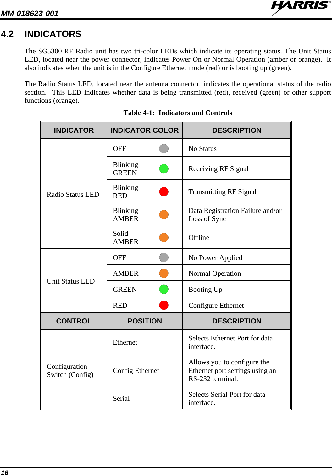


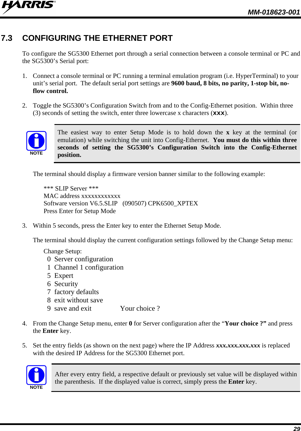

![MM-018623-001 34 4. When prompted for the “Flow (00) ?”: Press the Enter key. 5. When prompted for to “Enable passive mode (N) ?”: Press the Enter key. 6. When prompted for the “Enable bridge mode (N) ?”: Press the Enter key. 7. When prompted for the “Local Serial IP address”: Enter the desired IP address of the local serial port (i.e., 10.248.15.85 ), placing a period between the octets or press the Enter key to move to the next octet. 8. When prompted for the “Peer Serial IP address”: Enter the IP address assigned to the radio serial port (i.e., 10.248.15.86 ), placing a period between the octets or press the Enter key to move to the next octet. 9. When prompted for the “NAT IP address (000.000.000.000)”: Leave set to 000.000.000.000 placing a period between the octets or press the Enter key to move to the next octet. 10. When prompted for the “NAT IP address offset: (16) ?”: Press the Enter key. 11. When prompted for the “DNS Server IP address: address (000.000.000.000)”: Leave set to 000.000.000.000, placing a period between the octets or press the Enter key to move to the next octet. 12. When prompted for the “Allow broadcasts in (N) ?”: Press the Enter key. 13. When prompted for the “Monitor Connection Control (N) ?”: Press the Enter key. 14. When prompted for the “SLIP Client Mode (N) ?”: Press the Enter key. Static Map Table PROTO [Cloud Socket] [Ethernet Socket] 01: ICM 010.000.000.001:00000 <-> 192.168.001.001:00000 02: UDP 010.000.000.001:00000 <-> 192.168.001.001:00000 03: --- 000.000.000.000:00000 <-> 000.000.000.000:00000 04: --- 000.000.000.000:00000 <-> 000.000.000.000:00000 05: --- 000.000.000.000:00000 <-> 000.000.000.000:00000 06: --- 000.000.000.000:00000 <-> 000.000.000.000:00000 07: --- 000.000.000.000:00000 <-> 000.000.000.000:00000 08: --- 000.000.000.000:00000 <-> 000.000.000.000:00000 09: --- 000.000.000.000:00000 <-> 000.000.000.000:00000 10: --- 000.000.000.000:00000 <-> 000.000.000.000:00000 11: --- 000.000.000.000:00000 <-> 000.000.000.000:00000 12: --- 000.000.000.000:00000 <-> 000.000.000.000:00000 13: --- 000.000.000.000:00000 <-> 000.000.000.000:00000 14: --- 000.000.000.000:00000 <-> 000.000.000.000:00000 15. When prompted for to “Change Map Table? (N) ?”: Enter Y and press the Enter key. 16. When prompted for to “Clear Map Table? (N) ?”: Press the Enter key. 17. When prompted for to “Edit entry # (0 to exit): (0) ?: Enter 1](https://usermanual.wiki/HARRIS/TR-0064-E/User-Guide-1519026-Page-35.png)
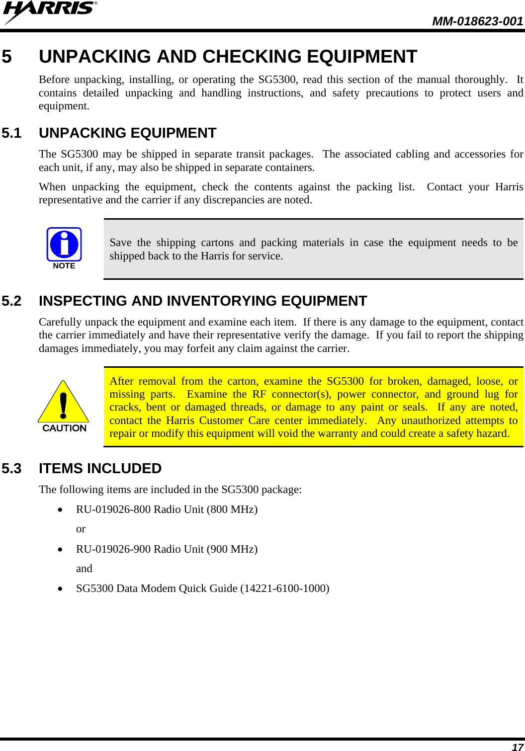
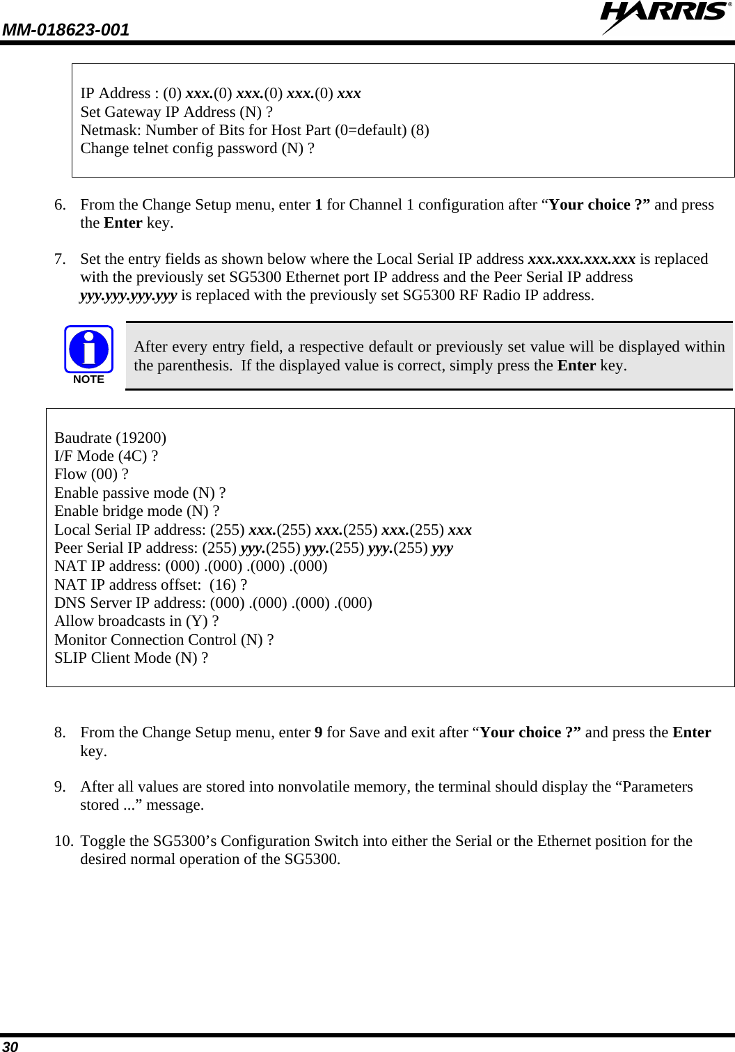
![MM-018623-001 35 18. When prompted for the “Map Cloud TCP, UDP or ICMP to Ethernet IP & Port T(CP) or U(DP) or (I)CMP”: Enter: • I for ICMP traffic • U for UDP traffic • T for TCP traffic 19. When prompted for the “Cloud Port #: (0) ?”: Enter the port number that was assigned at the source of the message i.e., (telnet port 23, HTTP port 80). 20. When prompted for the”Tto Port #: (0) ?”: Enter the port number that the destinstion application will want to see. If it is the same number assigned at the source of the message (i.e. telnet port 23, HTTP port 80), enter 0 for the cloud port and to port numbers. When both the cloud and two port numbers are set to zero no port translation takes place. 21. When prompted for the “At IP address”: Enter the destination IP address, (where you want the data sent to on the Ethernet port network.), placing a period between the octets or press the Enter key to move to the next octet. 22. When prompted for the “Edit entry # (0 to exit): (1) ?”: Enter 0 if all entries have been completed or the next table position to be configured. 23. If 0 was entered, you will be given the current static map table and asked if you wish to make changes. Review the entries, if correct enter “N;” otherwise, enter “Y” and make any needed corrections. Static Map Table PROTO [Cloud Socket] [Ethernet Socket] 01: ICM 010.000.000.001:00000 <-> 192.168.001.001:00000 02: UDP 010.000.000.001:00000 <-> 192.168.001.001:00000 03: --- 000.000.000.000:00000 <-> 000.000.000.000:00000 04: --- 000.000.000.000:00000 <-> 000.000.000.000:00000 05: --- 000.000.000.000:00000 <-> 000.000.000.000:00000 06: --- 000.000.000.000:00000 <-> 000.000.000.000:00000 07: --- 000.000.000.000:00000 <-> 000.000.000.000:00000 08: --- 000.000.000.000:00000 <-> 000.000.000.000:00000 09: --- 000.000.000.000:00000 <-> 000.000.000.000:00000 10: --- 000.000.000.000:00000 <-> 000.000.000.000:00000 11: --- 000.000.000.000:00000 <-> 000.000.000.000:00000 12: --- 000.000.000.000:00000 <-> 000.000.000.000:00000 13: --- 000.000.000.000:00000 <-> 000.000.000.000:00000 14: --- 000.000.000.000:00000 <-> 000.000.000.000:00000 Change Map Table? (N) ? 24. When the following information is displayed select menu item “9” followed by the Enter key to save changes and exit. *** basic parameters Hardware: Ethernet TPI](https://usermanual.wiki/HARRIS/TR-0064-E/User-Guide-1519026-Page-36.png)
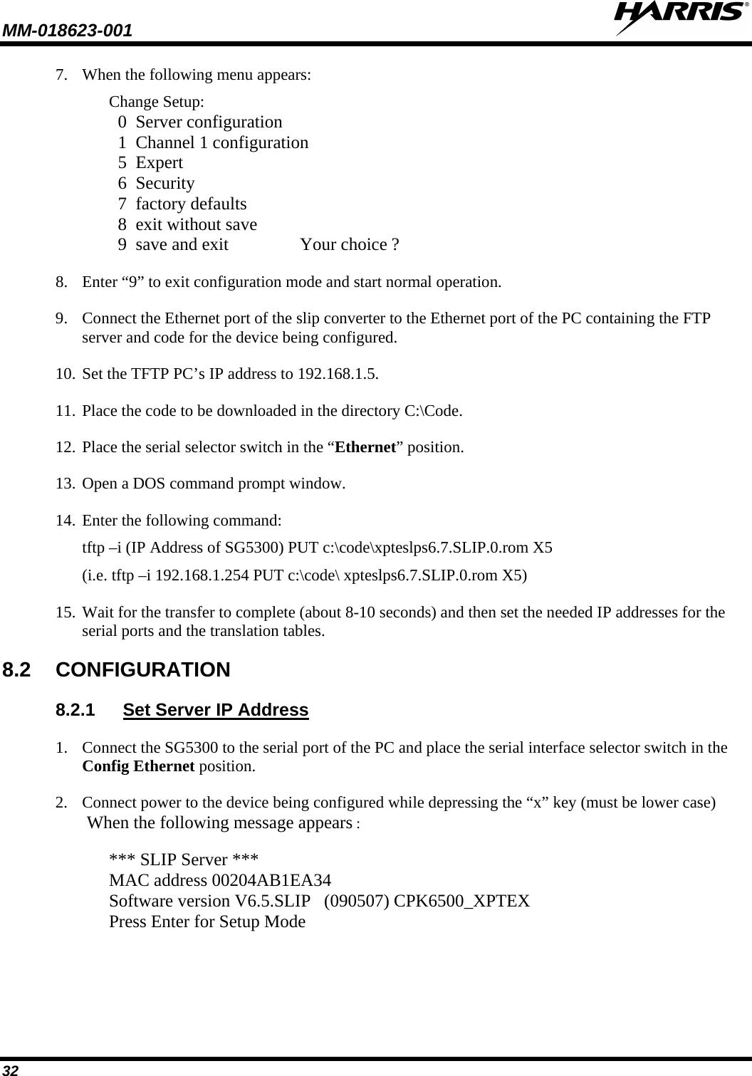
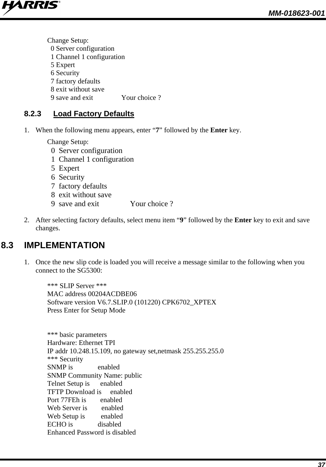
![MM-018623-001 36 IP addr 192.168.1.254, no gateway set,netmask 255.255.255.0 *** Security SNMP is enabled SNMP Community Name: public Telnet Setup is enabled TFTP Download is enabled Port 77FEh is enabled Web Server is enabled Web Setup is enabled ECHO is disabled Enhanced Password is disabled ***************** Channel 1 ***************** Baudrate 19200, I/F Mode 4C, Flow 00 CPU performance : Standard Local Serial IP address 10.0.0.2 Peer Serial IP address 10.0.0.1 NAT IP address 0.0.0.0 NAT IP address offset 16 DNS Server IP address 0.0.0.0 Passive Mode: disabled Bridge Mode: disabled Allow broadcasts: disabled Monitor Connection Control: disabled SLIP Client Mode: disabled Static Map Table PROTO [Cloud Socket] [Ethernet Socket] 01: ICM 010.000.000.001:00000 <-> 192.168.001.001:00000 02: UDP 010.000.000.001:00000 <-> 192.168.001.001:00000 03: --- 000.000.000.000:00000 <-> 000.000.000.000:00000 04: --- 000.000.000.000:00000 <-> 000.000.000.000:00000 05: --- 000.000.000.000:00000 <-> 000.000.000.000:00000 06: --- 000.000.000.000:00000 <-> 000.000.000.000:00000 07: --- 000.000.000.000:00000 <-> 000.000.000.000:00000 08: --- 000.000.000.000:00000 <-> 000.000.000.000:00000 09: --- 000.000.000.000:00000 <-> 000.000.000.000:00000 10: --- 000.000.000.000:00000 <-> 000.000.000.000:00000 11: --- 000.000.000.000:00000 <-> 000.000.000.000:00000 12: --- 000.000.000.000:00000 <-> 000.000.000.000:00000 13: --- 000.000.000.000:00000 <-> 000.000.000.000:00000 14: --- 000.000.000.000:00000 <-> 000.000.000.000:00000 *** Expert CPU performance: Regular Monitor Mode @ bootup : enabled MTU Size: 1400 Alternate MAC: disabled Ethernet connection type: auto-negotiate](https://usermanual.wiki/HARRIS/TR-0064-E/User-Guide-1519026-Page-37.png)
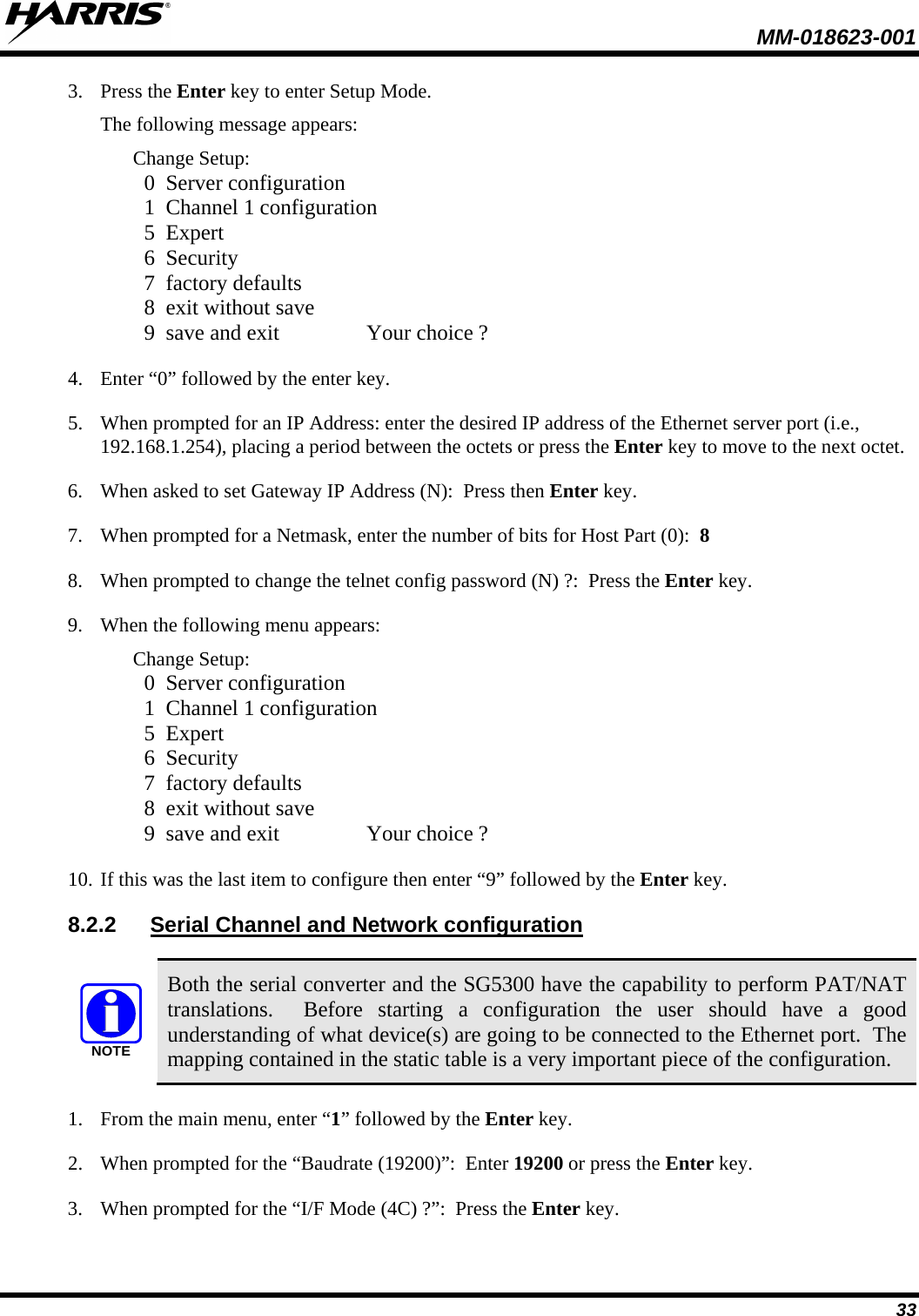
![MM-018623-001 38 ***************** Channel 1 ***************** Baudrate 9600, I/F Mode 4C, Flow 00 CPU performance : Standard Local Serial IP address 255.255.255.255 Peer Serial IP address 255.255.255.255 NAT IP address 255.255.255.255 DNS Server IP address 255.255.255.255 Passive Mode: enabled Bridge Mode: enabled Allow broadcasts: enabled Monitor Connection Control: enabled SLIP Client Mode: enabled Static Map Table PROTO [Cloud Socket] [Ethernet Socket] 01: --- 000.000.000.000:00000 <-> 000.000.000.000:00000 02: --- 000.000.000.000:00000 <-> 000.000.000.000:00000 03: --- 000.000.000.000:00000 <-> 000.000.000.000:00000 04: --- 000.000.000.000:00000 <-> 000.000.000.000:00000 05: --- 000.000.000.000:00000 <-> 000.000.000.000:00000 06: --- 000.000.000.000:00000 <-> 000.000.000.000:00000 07: --- 000.000.000.000:00000 <-> 000.000.000.000:00000 08: --- 000.000.000.000:00000 <-> 000.000.000.000:00000 09: --- 000.000.000.000:00000 <-> 000.000.000.000:00000 10: --- 000.000.000.000:00000 <-> 000.000.000.000:00000 11: --- 000.000.000.000:00000 <-> 000.000.000.000:00000 12: --- 000.000.000.000:00000 <-> 000.000.000.000:00000 13: --- 000.000.000.000:00000 <-> 000.000.000.000:00000 14: --- 000.000.000.000:00000 <-> 000.000.000.000:00000 *** Expert CPU performance: Regular Monitor Mode @ bootup : enabled MTU Size: 1400 Alternate MAC: disabled Ethernet connection type: auto-negotiate Change Setup: 0 Server configuration 1 Channel 1 configuration 5 Expert 6 Security 7 factory defaults 8 exit without save 9 save and exit Your choice ?](https://usermanual.wiki/HARRIS/TR-0064-E/User-Guide-1519026-Page-39.png)
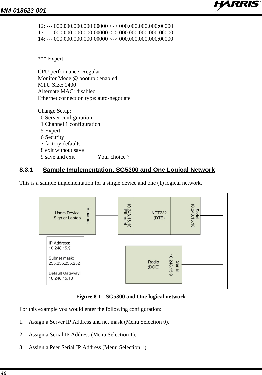
![MM-018623-001 39 2. If this is to be a new installation, select menu option “7” followed by menu option “9.” If you selected menu option “7,” you will get the following configuration the next time you connect to the SG5300: • An address for the server port has been set to 192.168.1.254 with a subnet mask of 255.255.255.0. • The serial ports have been assigned along with basic static table entries. *** basic parameters Hardware: Ethernet TPI IP addr 192.168.1.254, no gateway set,netmask 255.255.255.0 *** Security SNMP is enabled SNMP Community Name: public Telnet Setup is enabled TFTP Download is enabled Port 77FEh is enabled Web Server is enabled Web Setup is enabled ECHO is disabled Enhanced Password is disabled ***************** Channel 1 ***************** Baudrate 19200, I/F Mode 4C, Flow 00 CPU performance : Standard Local Serial IP address 10.0.0.2 Peer Serial IP address 10.0.0.1 NAT IP address 0.0.0.0 NAT IP address offset 16 DNS Server IP address 0.0.0.0 Passive Mode: disabled Bridge Mode: disabled Allow broadcasts: disabled Monitor Connection Control: disabled SLIP Client Mode: disabled Static Map Table PROTO [Cloud Socket] [Ethernet Socket] 01: ICM 010.000.000.001:00000 <-> 192.168.001.001:00000 02: UDP 010.000.000.001:00000 <-> 192.168.001.001:00000 03: --- 000.000.000.000:00000 <-> 000.000.000.000:00000 04: --- 000.000.000.000:00000 <-> 000.000.000.000:00000 05: --- 000.000.000.000:00000 <-> 000.000.000.000:00000 06: --- 000.000.000.000:00000 <-> 000.000.000.000:00000 07: --- 000.000.000.000:00000 <-> 000.000.000.000:00000 08: --- 000.000.000.000:00000 <-> 000.000.000.000:00000 09: --- 000.000.000.000:00000 <-> 000.000.000.000:00000 10: --- 000.000.000.000:00000 <-> 000.000.000.000:00000 11: --- 000.000.000.000:00000 <-> 000.000.000.000:00000](https://usermanual.wiki/HARRIS/TR-0064-E/User-Guide-1519026-Page-40.png)
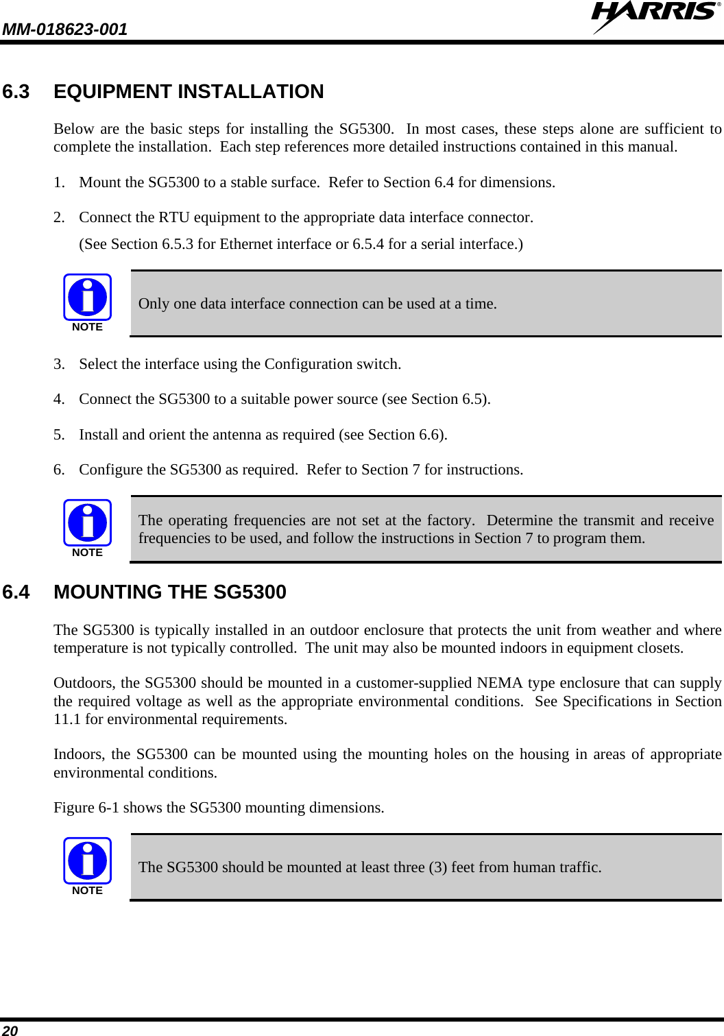
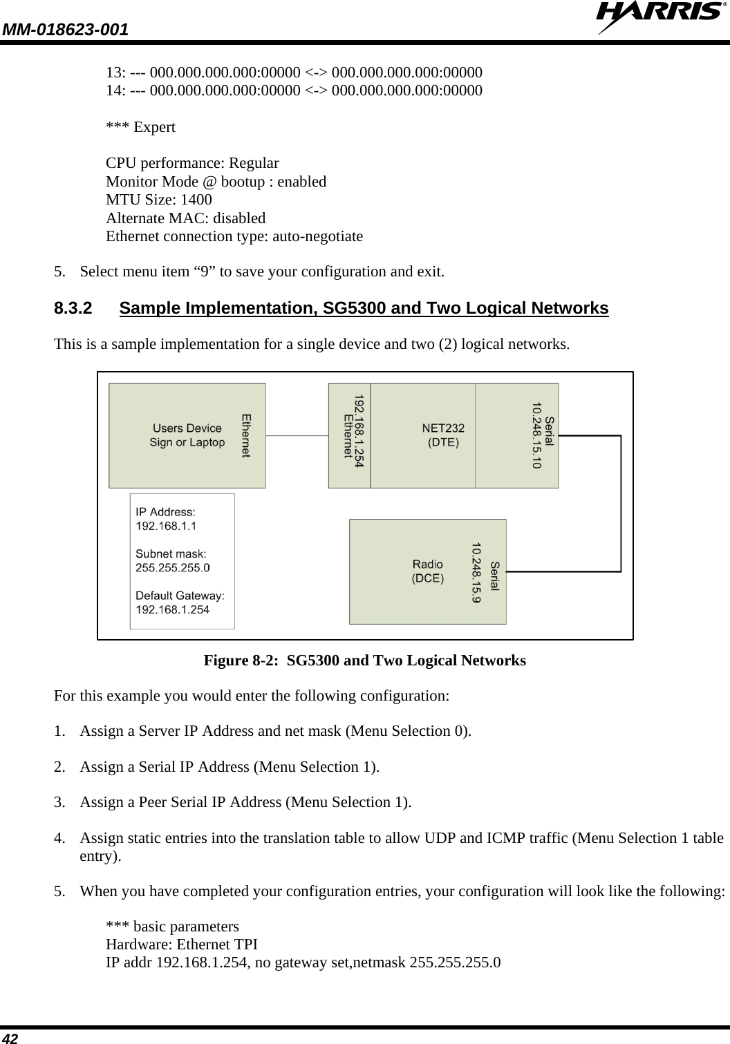
![MM-018623-001 41 4. Assign static entries into the translation table to allow UDP and ICMP traffic (Menu Selection 1 table entry). When you have completed your configuration entries, your configuration will look like the following: *** basic parameters Hardware: Ethernet TPI IP addr 10.248.15.10, no gateway set,netmask 255.255.255.0 *** Security SNMP is enabled SNMP Community Name: public Telnet Setup is enabled TFTP Download is enabled Port 77FEh is enabled Web Server is enabled Web Setup is enabled ECHO is disabled Enhanced Password is disabled ***************** Channel 1 ***************** Baudrate 19200, I/F Mode 4C, Flow 00 CPU performance : Standard Local Serial IP address 10.248.15.10 Peer Serial IP address 10.248.15.9 NAT IP address 0.0.0.0 NAT IP address offset 16 DNS Server IP address 0.0.0.0 Passive Mode: disabled Bridge Mode: disabled Allow broadcasts: disabled Monitor Connection Control: disabled SLIP Client Mode: disabled Static Map Table PROTO [Cloud Socket] [Ethernet Socket] 01: ICM 010.248.015.009:00000 <-> 010.248.015.009:00000 (Sends all ICMP traffic from the peer serial port to 010.248.015.009 at the Ethernet port) 02: UDP 010.248.015.010:00000 <-> 010.248.015.009:00000 (Sends all UDP traffic from the peer serial port to 010.248.015.009 at the Ethernet port) 03: --- 000.000.000.000:00000 <-> 000.000.000.000:00000 04: --- 000.000.000.000:00000 <-> 000.000.000.000:00000 05: --- 000.000.000.000:00000 <-> 000.000.000.000:00000 06: --- 000.000.000.000:00000 <-> 000.000.000.000:00000 07: --- 000.000.000.000:00000 <-> 000.000.000.000:00000 08: --- 000.000.000.000:00000 <-> 000.000.000.000:00000 09: --- 000.000.000.000:00000 <-> 000.000.000.000:00000 10: --- 000.000.000.000:00000 <-> 000.000.000.000:00000 11: --- 000.000.000.000:00000 <-> 000.000.000.000:00000 12: --- 000.000.000.000:00000 <-> 000.000.000.000:00000](https://usermanual.wiki/HARRIS/TR-0064-E/User-Guide-1519026-Page-42.png)
![MM-018623-001 43 *** Security SNMP is enabled SNMP Community Name: public Telnet Setup is enabled TFTP Download is enabled Port 77FEh is enabled Web Server is enabled Web Setup is enabled ECHO is disabled Enhanced Password is disabled ***************** Channel 1 ***************** Baudrate 19200, I/F Mode 4C, Flow 00 CPU performance : Standard Local Serial IP address 10.248.15.10 Peer Serial IP address 10.248.15.9 NAT IP address 0.0.0.0 NAT IP address offset 16 DNS Server IP address 0.0.0.0 Passive Mode: disabled Bridge Mode: disabled Allow broadcasts: disabled Monitor Connection Control: disabled SLIP Client Mode: disabled Static Map Table PROTO [Cloud Socket] [Ethernet Socket] 01: ICM 010.248.015.009:00000 <-> 192.168.001.001:00000 (Sends all ICMP traffic to 192.168.001.001 ) 02: UDP 010.248.015.009:00000 <-> 192.168.001.001:00000 (Sends all ICMP traffic to 192.168.001.001 ) 03: --- 000.000.000.000:00000 <-> 000.000.000.000:00000 04: --- 000.000.000.000:00000 <-> 000.000.000.000:00000 05: --- 000.000.000.000:00000 <-> 000.000.000.000:00000 06: --- 000.000.000.000:00000 <-> 000.000.000.000:00000 07: --- 000.000.000.000:00000 <-> 000.000.000.000:00000 08: --- 000.000.000.000:00000 <-> 000.000.000.000:00000 09: --- 000.000.000.000:00000 <-> 000.000.000.000:00000 10: --- 000.000.000.000:00000 <-> 000.000.000.000:00000 11: --- 000.000.000.000:00000 <-> 000.000.000.000:00000 12: --- 000.000.000.000:00000 <-> 000.000.000.000:00000 13: --- 000.000.000.000:00000 <-> 000.000.000.000:00000 14: --- 000.000.000.000:00000 <-> 000.000.000.000:00000 *** Expert CPU performance: Regular Monitor Mode @ bootup : enabled](https://usermanual.wiki/HARRIS/TR-0064-E/User-Guide-1519026-Page-44.png)
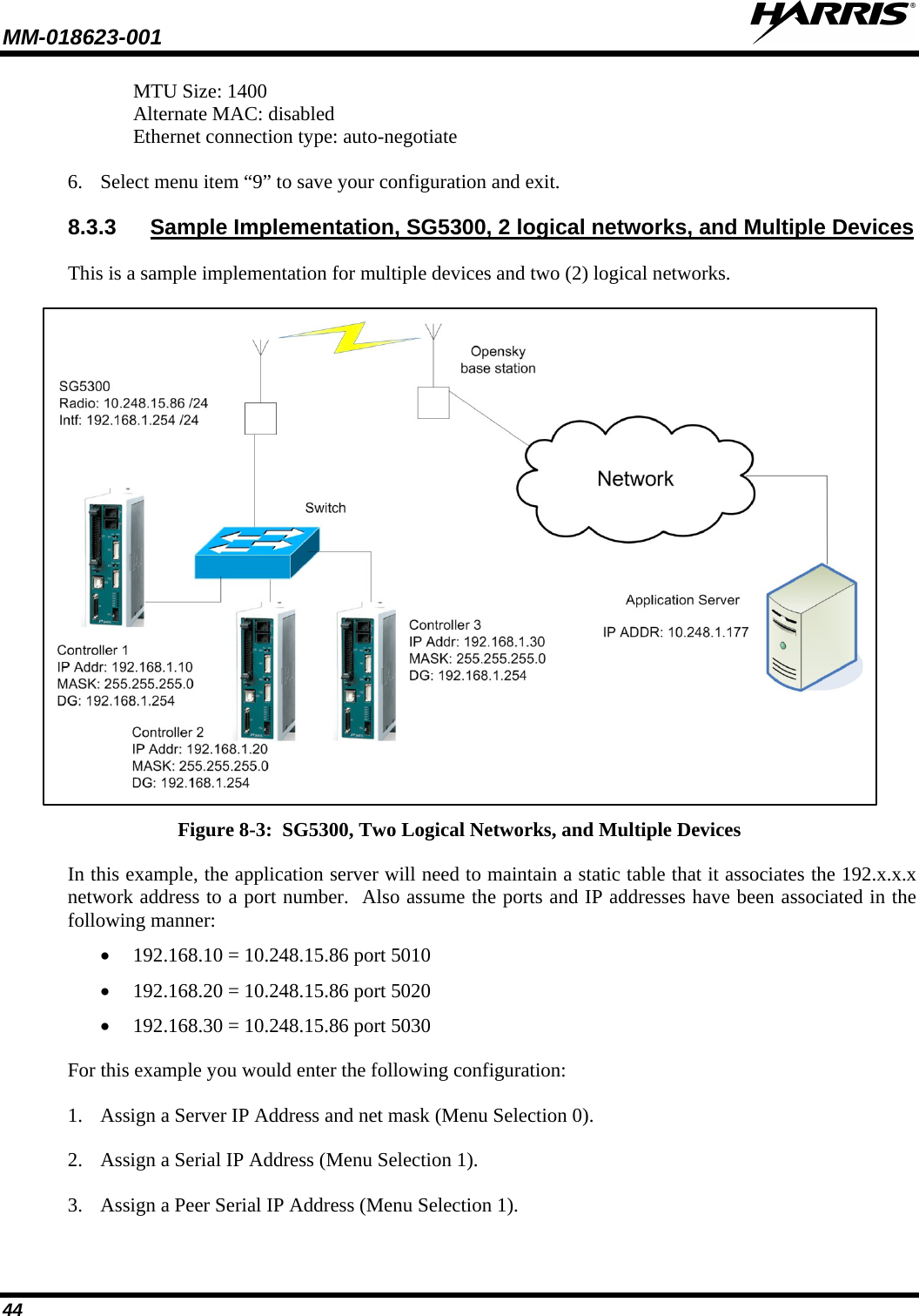
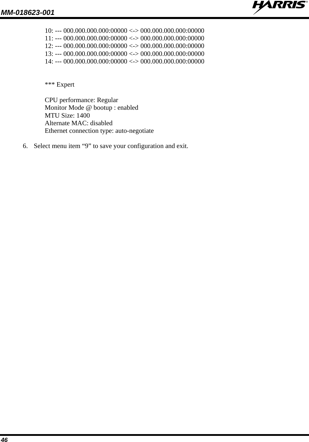
![MM-018623-001 45 4. Assign static entries into the translation table to allow UDP and ICMP traffic (Menu Selection 1 table entry). 5. When you have completed your configuration entries, you configuration will look like the following data: *** basic parameters Hardware: Ethernet TPI IP addr 192.168.1.254, no gateway set,netmask 255.255.255.0 *** Security SNMP is enabled SNMP Community Name: public Telnet Setup is enabled TFTP Download is enabled Port 77FEh is enabled Web Server is enabled Web Setup is enabled ECHO is disabled Enhanced Password is disabled ***************** Channel 1 ***************** Baudrate 19200, I/F Mode 4C, Flow 00 CPU performance : Standard Local Serial IP address 10.248.15.85 Peer Serial IP address 10.248.15.86 NAT IP address 0.0.0.0 NAT IP address offset 16 DNS Server IP address 0.0.0.0 Passive Mode: disabled Bridge Mode: disabled Allow broadcasts: disabled Monitor Connection Control: disabled SLIP Client Mode: disabled Static Map Table PROTO [Cloud Socket] [Ethernet Socket] 01: ICM 010.248.015.086:00000 <-> 192.168.001.010:00000 (Sends all ICMP traffic to 192.168.001.010 ) 02: UDP 010.248.015.086:05010 <-> 192.168.001.010:00000 (Sends all ICMP traffic to 192.168.001.010 ) 03: UDP 010.248.015.086:05020 <-> 192.168.001.020:00000 (Sends all ICMP traffic to 192.168.001.020 ) 04: UDP 010.248.015.086:05030 <-> 192.168.001.030:00000 (Sends all ICMP traffic to 192.168.001.030 ) 05: --- 000.000.000.000:00000 <-> 000.000.000.000:00000 06: --- 000.000.000.000:00000 <-> 000.000.000.000:00000 07: --- 000.000.000.000:00000 <-> 000.000.000.000:00000 08: --- 000.000.000.000:00000 <-> 000.000.000.000:00000 09: --- 000.000.000.000:00000 <-> 000.000.000.000:00000](https://usermanual.wiki/HARRIS/TR-0064-E/User-Guide-1519026-Page-46.png)