HARRIS TR-0066-E 800 MHz P5500, 800 MHz P5300 User Manual Manual
HARRIS CORPORATION 800 MHz P5500, 800 MHz P5300 Manual
UserManual.wiki
>
HARRIS
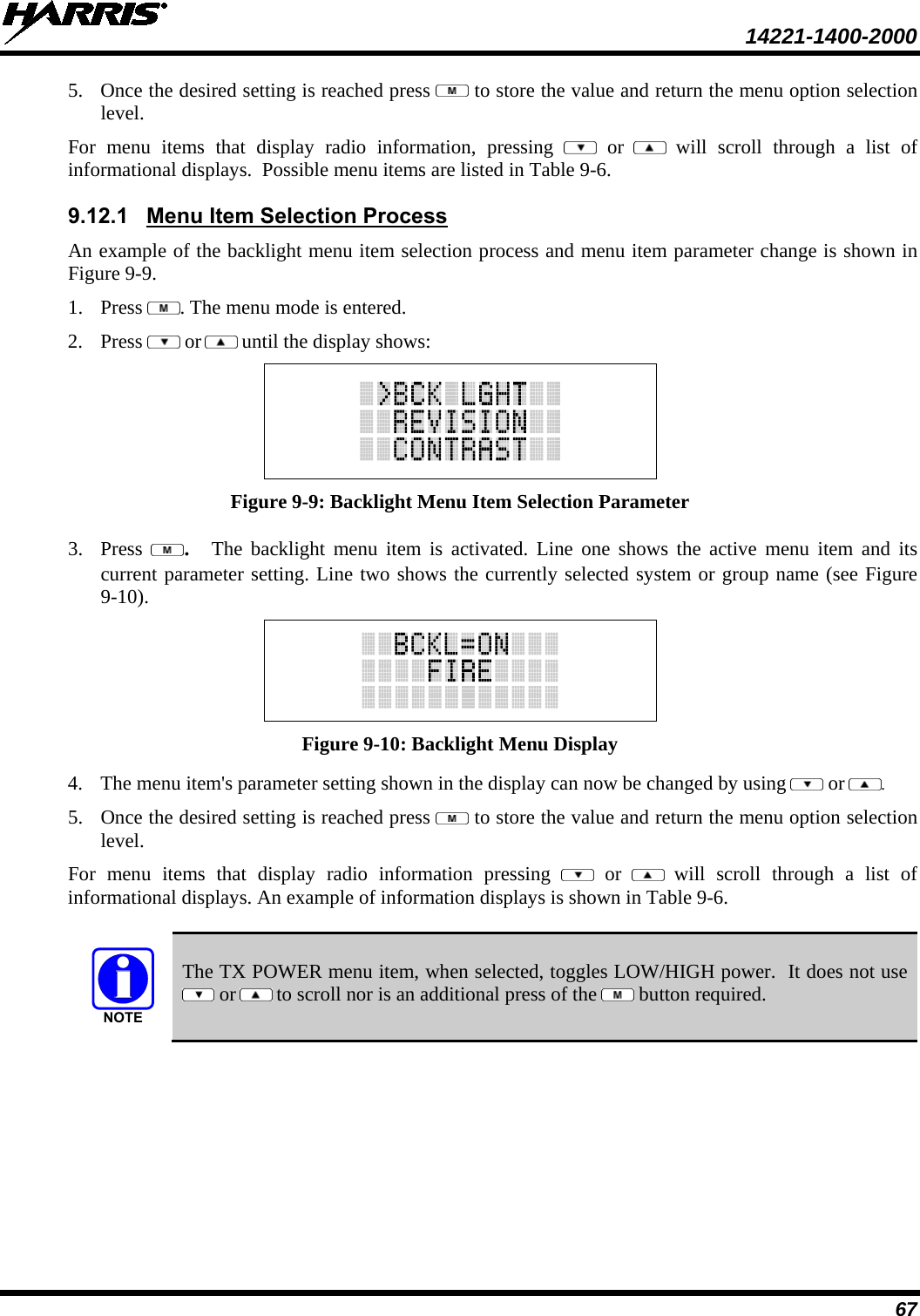
>
TR 0066 E User Manual
Manual
Navigation menu
Upload a User Manual
Namespaces
Wiki Guide
HTML
PDF
Info
Views
User Manual
Discussion / Help
Navigation


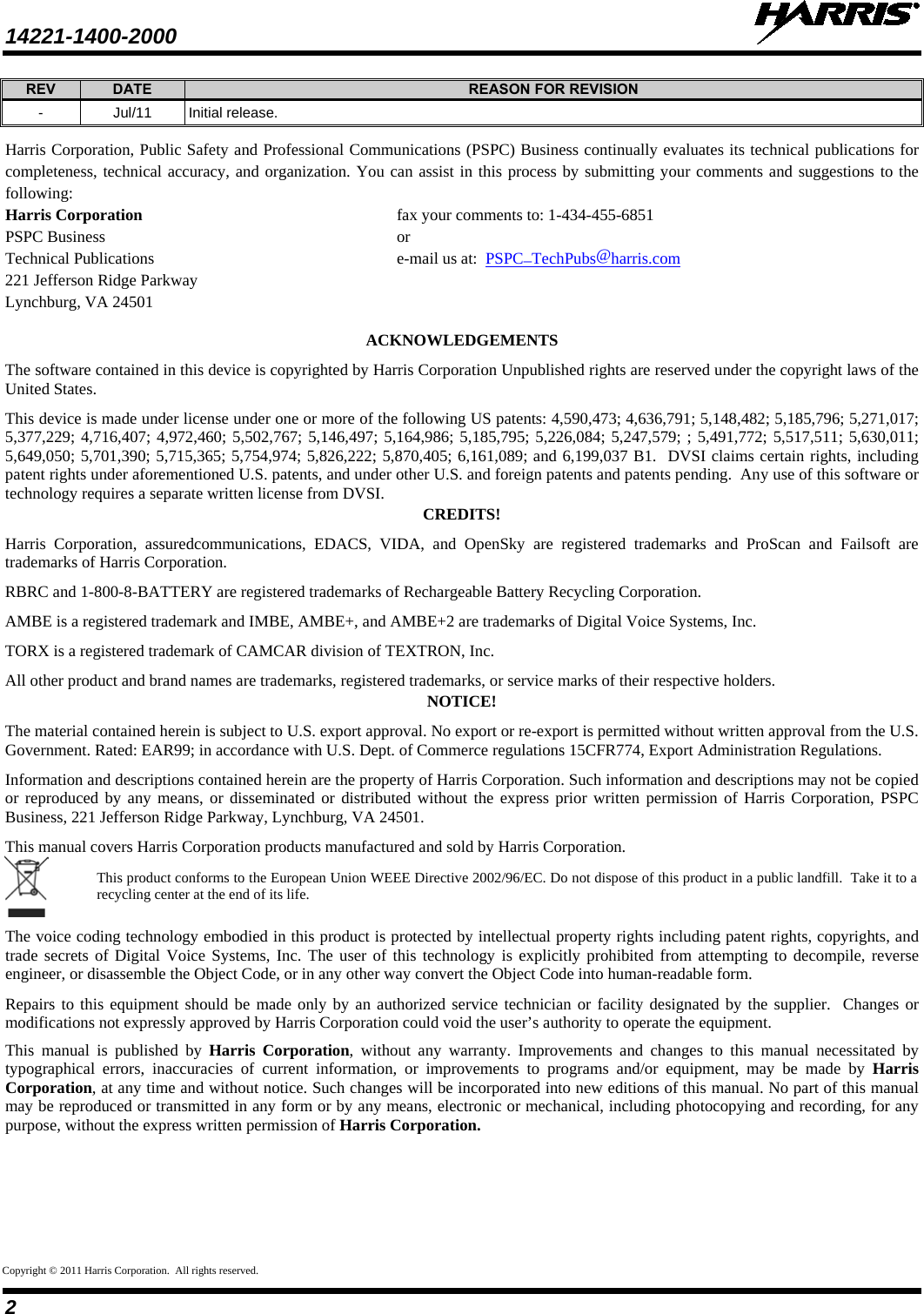
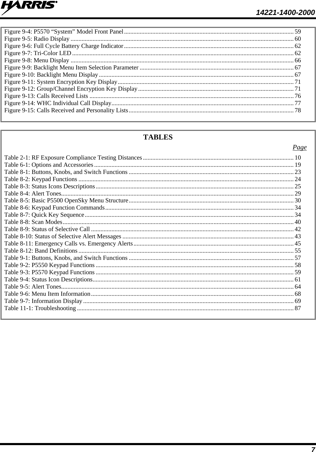

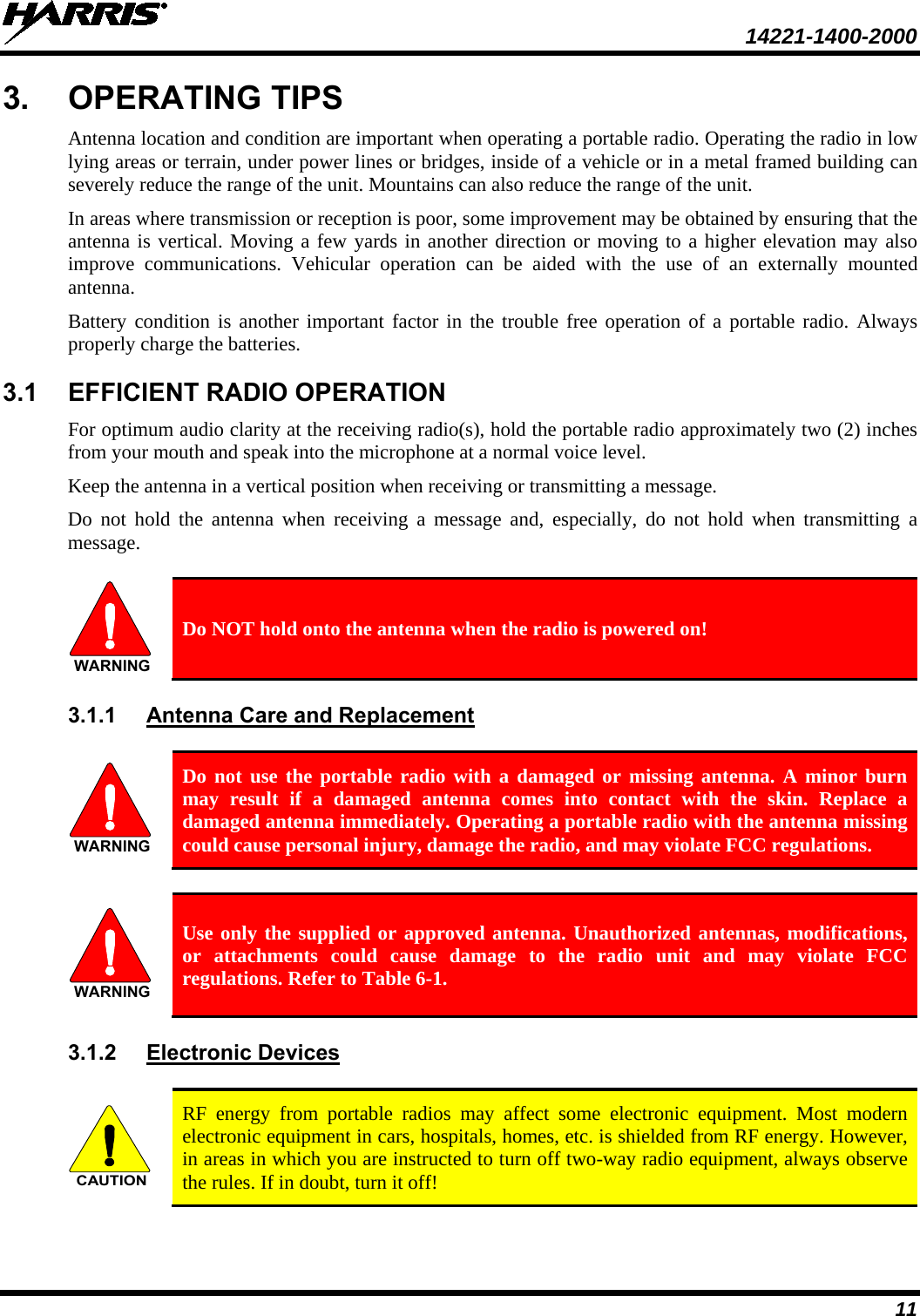


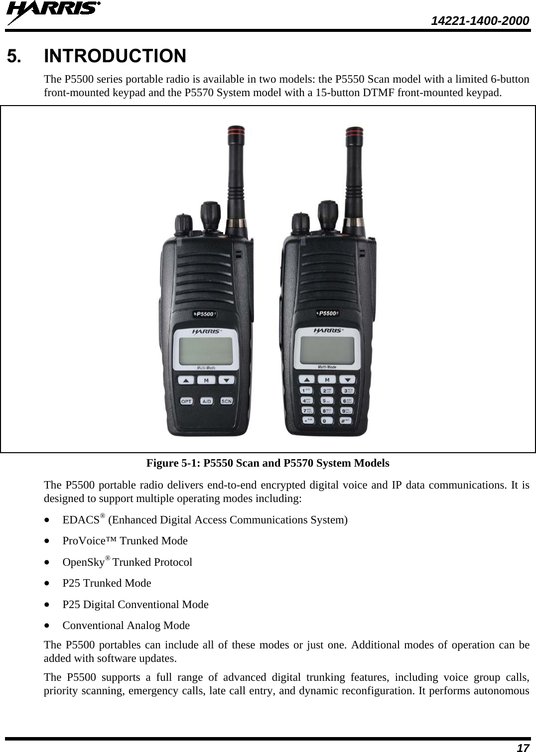
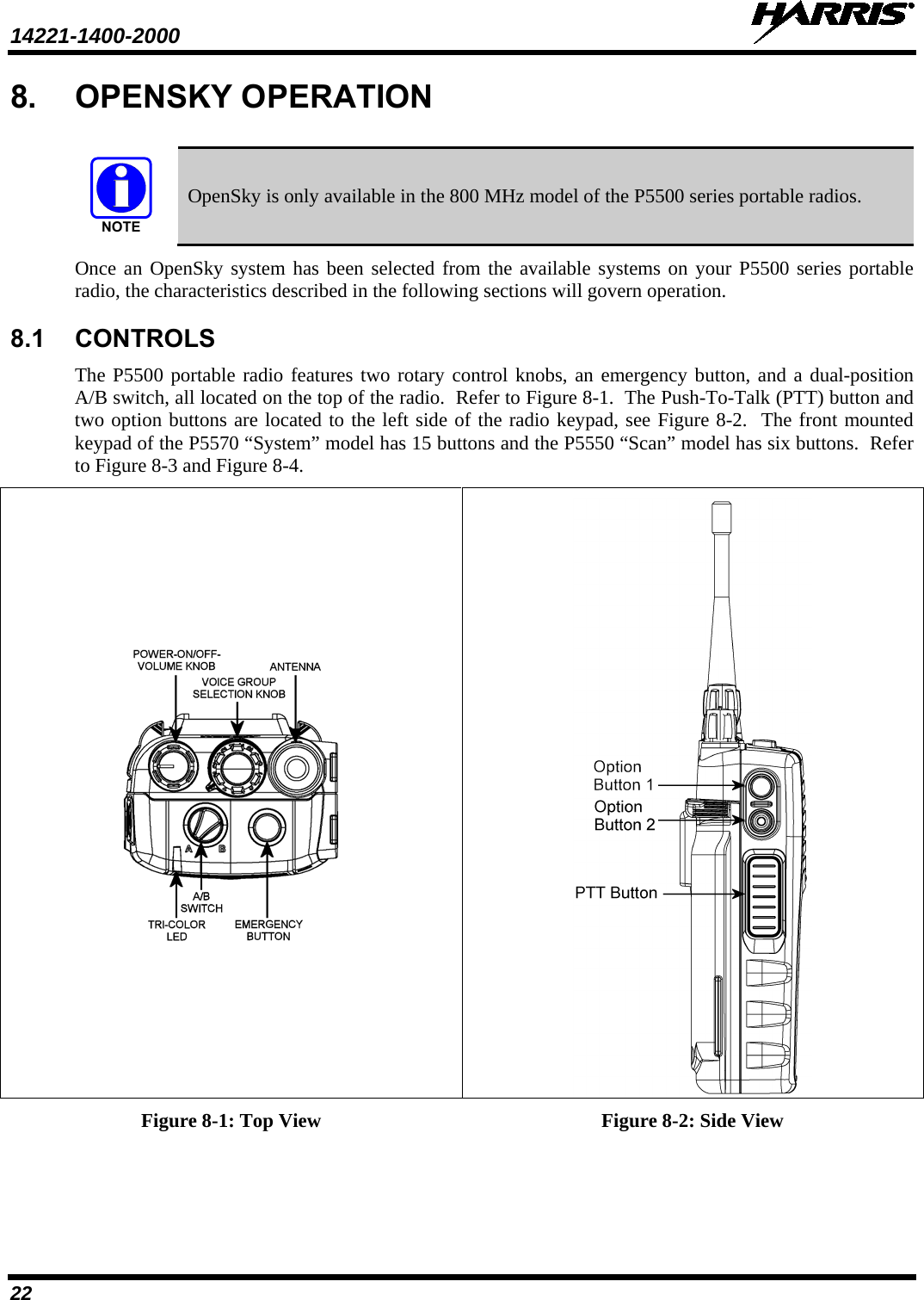
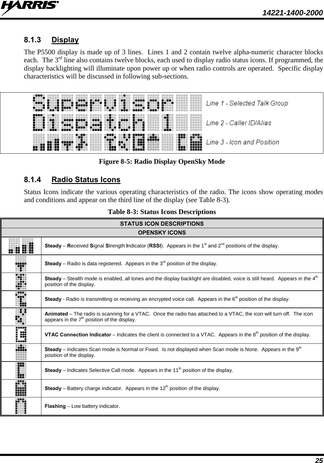
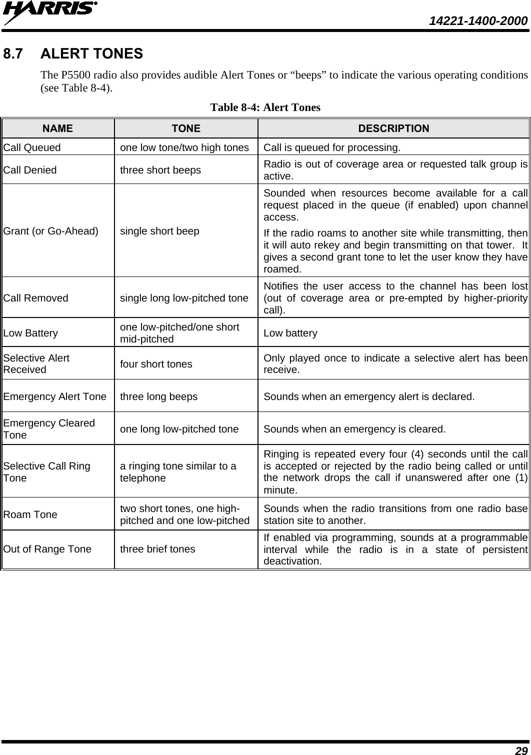
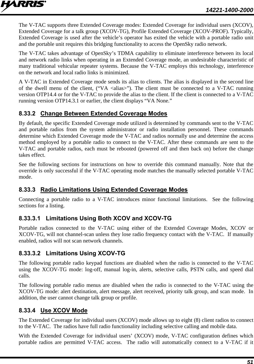
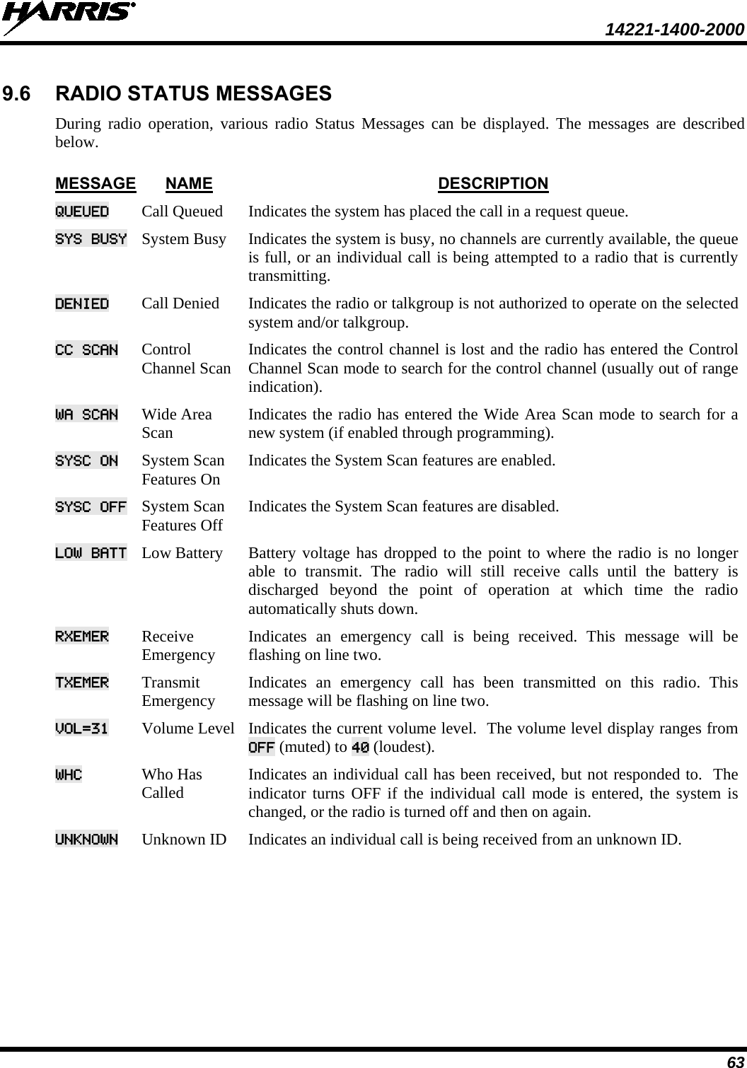
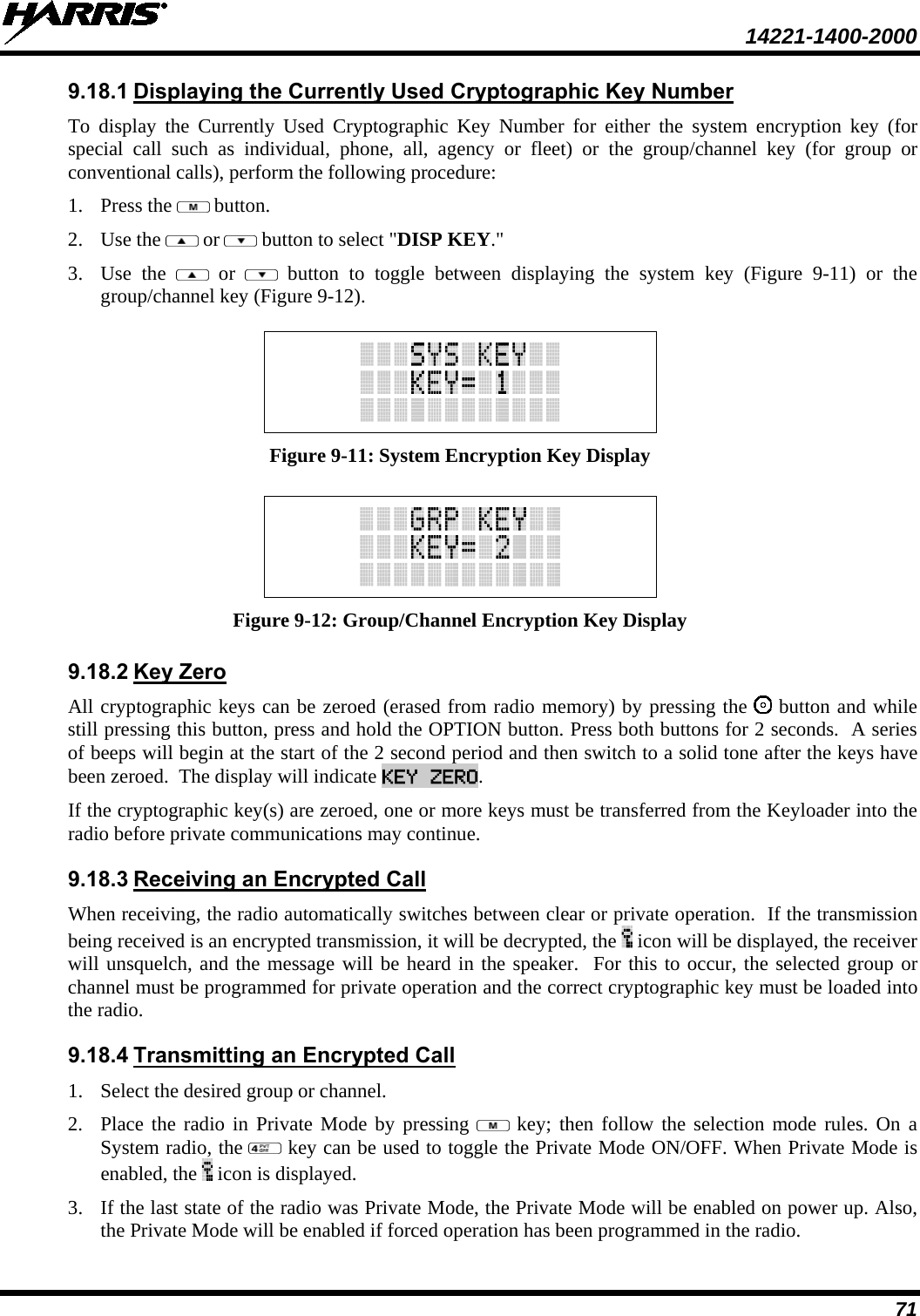
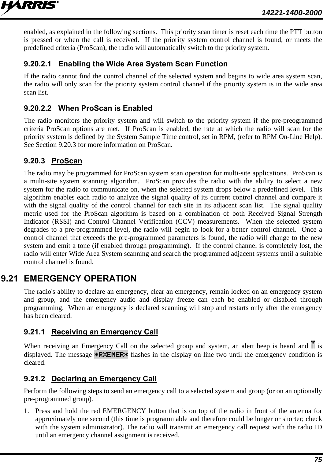
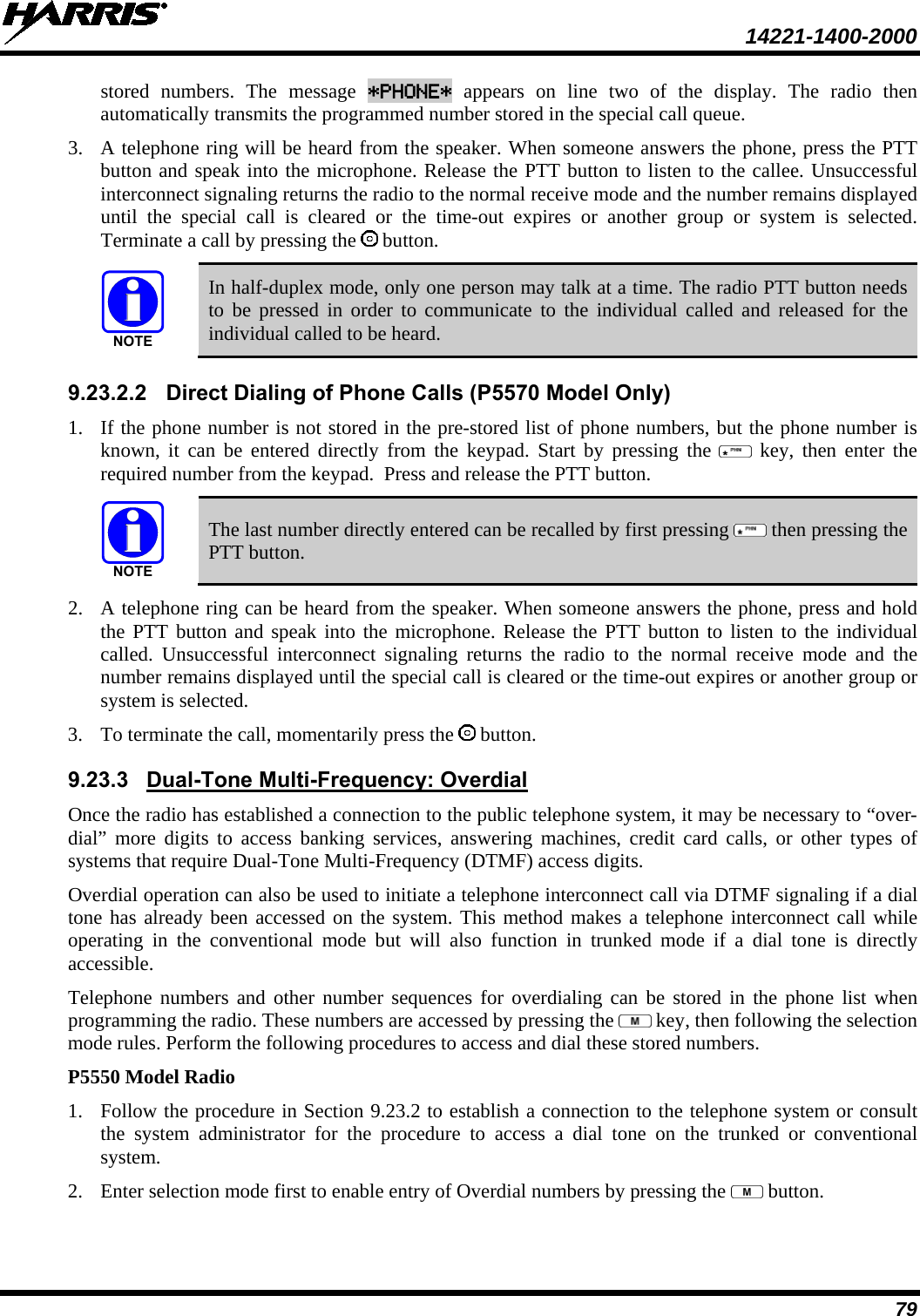
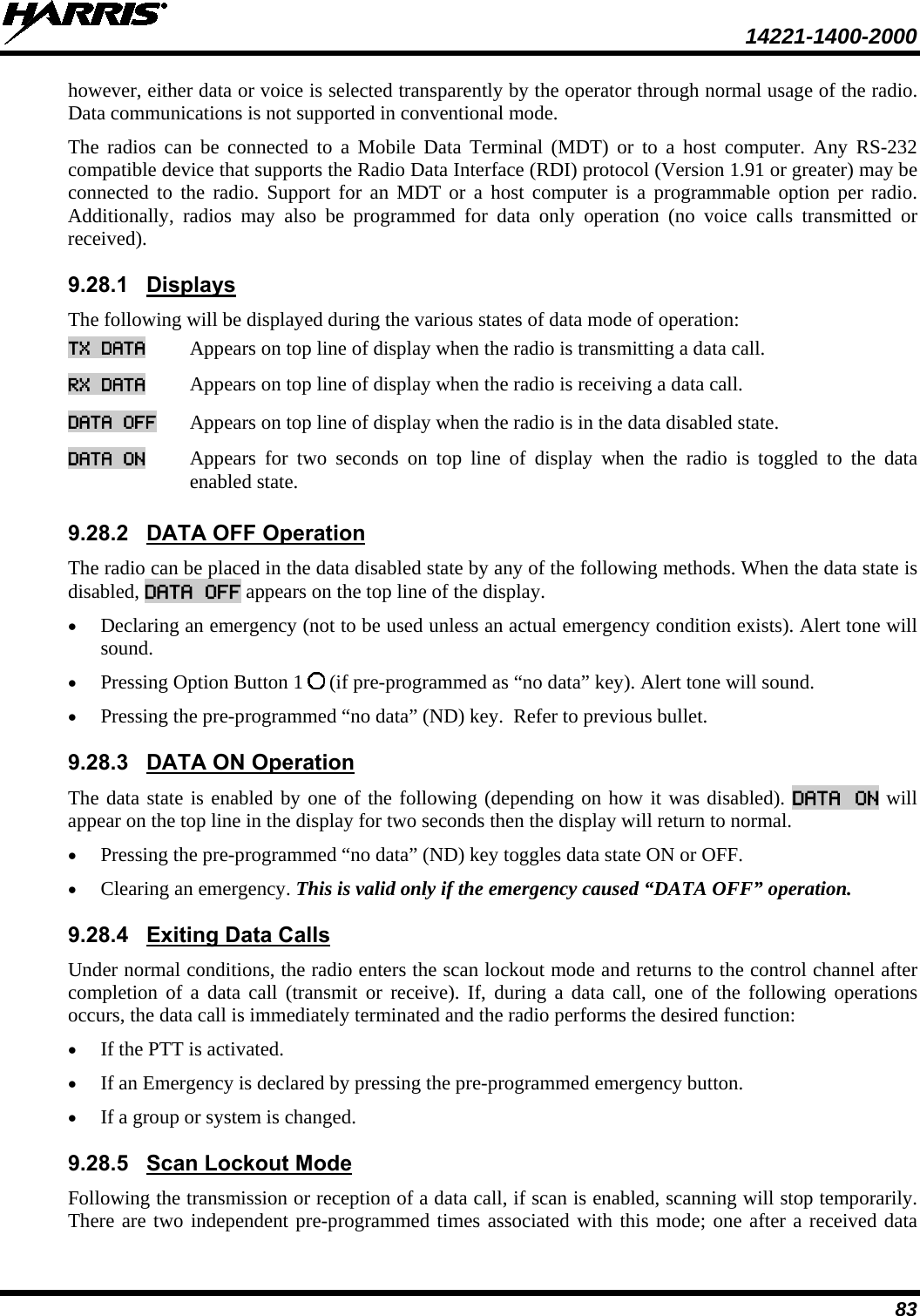
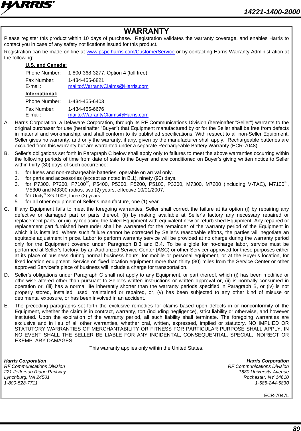
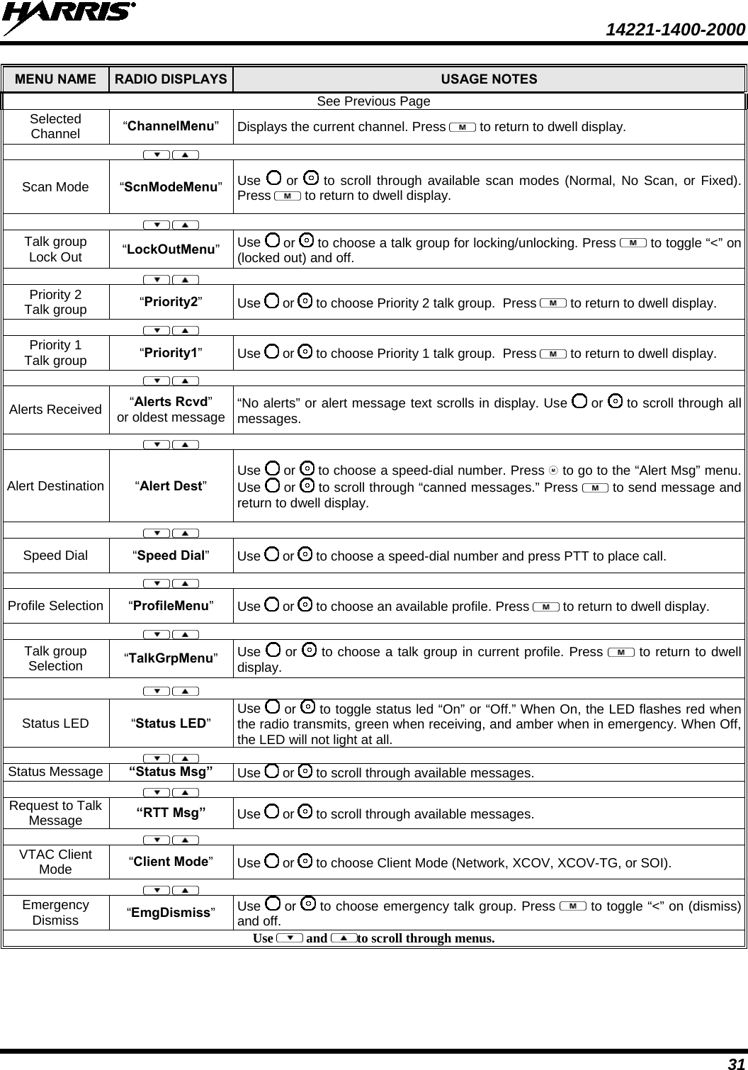
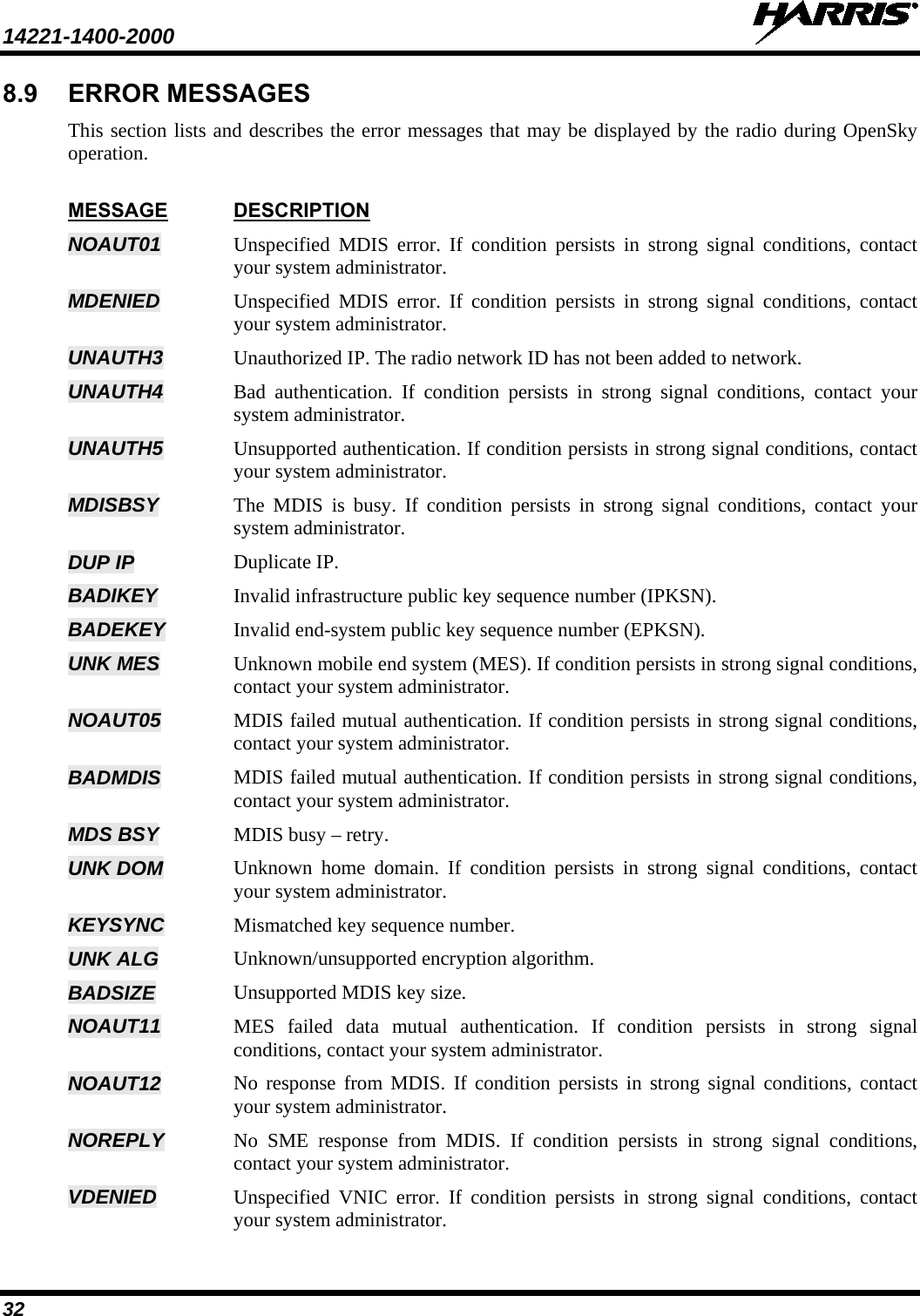
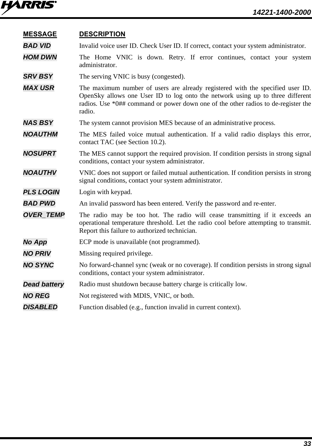
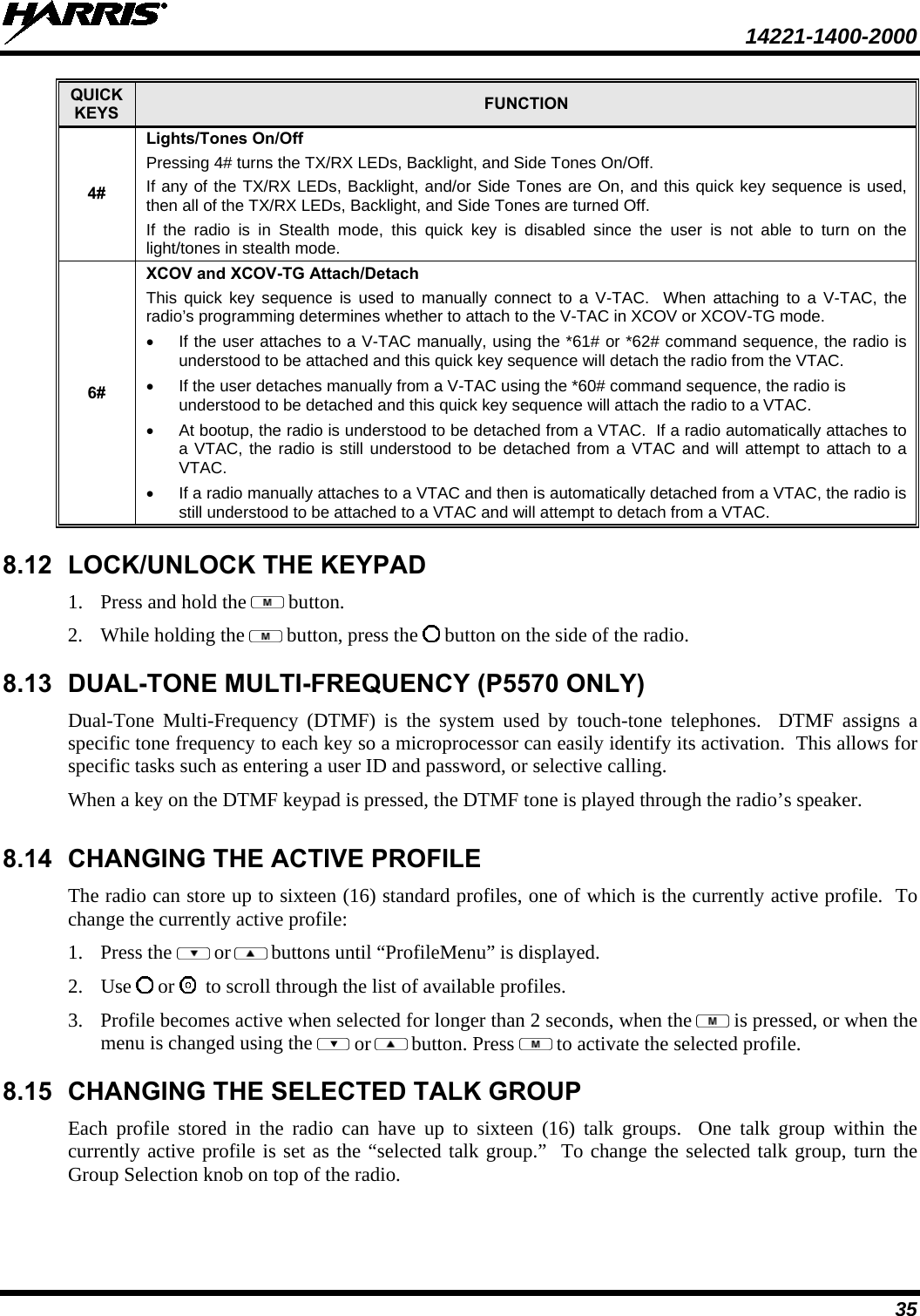
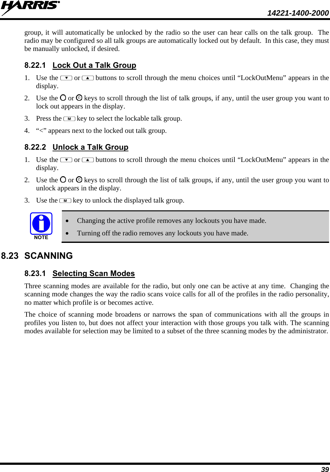
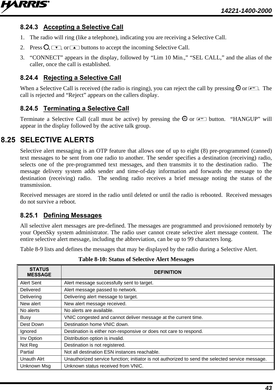
![14221-1400-2000 30 8.8 BASIC MENU STRUCTURE Table 8-5 illustrates the basic P5500 OpenSky menu structure. Menu items will vary depending upon system programming, radio hardware, and optional configurations. All menus except the dwell display menu can be turned off by network administration personnel. Table 8-5: Basic P5500 OpenSky Menu Structure MENU NAME RADIO DISPLAYS USAGE NOTES To/From Dwell Display Engineering Display bit-error rates and RSSI data Displays radio system connection data. For engineering use. Silent Emergency “SilentEmerg” Use or to toggle between OFF/ON. Press to enable. Operating Mode “App Mode” Use or to choose an available mode (OTP, OCF, or ECP). Press and confirm (Y/N) with or and again. GPS Fix “GPS” GPS latitude and longitude position of currently tuned-to base station [“GPS (Site)”] or V-TAC (“GPS”) scrolls across top line of the display. “GPS (Aged)” indicates VTAC coordinates haven’t been updated for more that 2 minutes. User ID “User ID” User’s identification/name scrolls across top line of the display (if programmed). IP Address “IP Address” Radio’s Internet Protocol (IP) address scrolls across top line of the display. Station Identification “Station ID” Station’s identification/name scrolls across top line of the display (if programmed). Stealth Mode (display backlight is disabled) “StealthMenu” Use or to turn Stealth Mode “On” or “Off.” Treble Level “Treble Menu” Use or to choose speaker treble level (LOW, MEDIUM, MEDHIGH, or HIGH). Press to return to dwell display. Display Brightness “Bright Menu” Use or to brighten or dim backlighting. Press to return to dwell display. Side Tone Level “Side Menu” Use or to choose side tone level (OFF, LOW, MED, or HIGH). Press to return to dwell display. See Next Page](https://usermanual.wiki/HARRIS/TR-0066-E/User-Guide-1537752-Page-31.png)
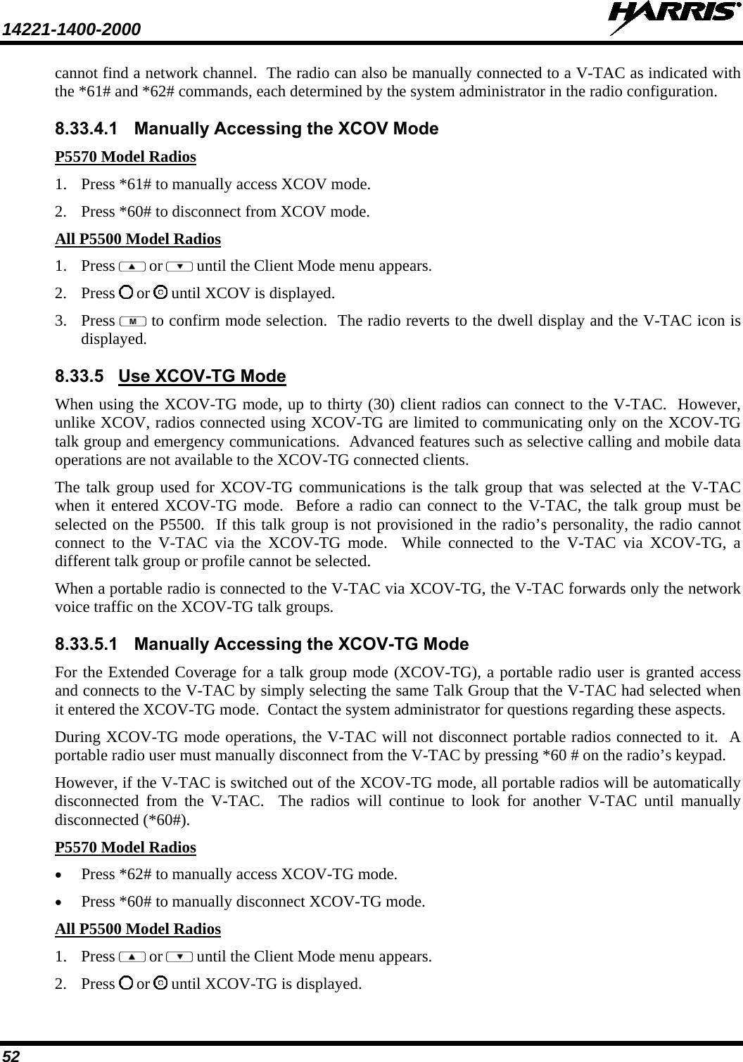
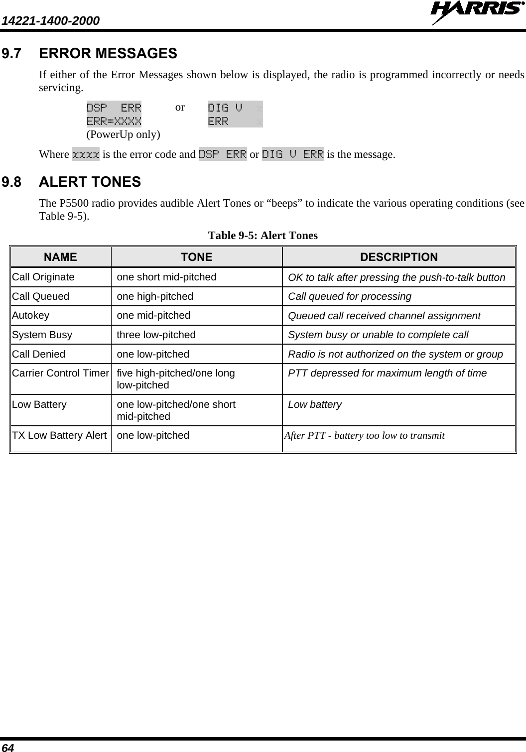
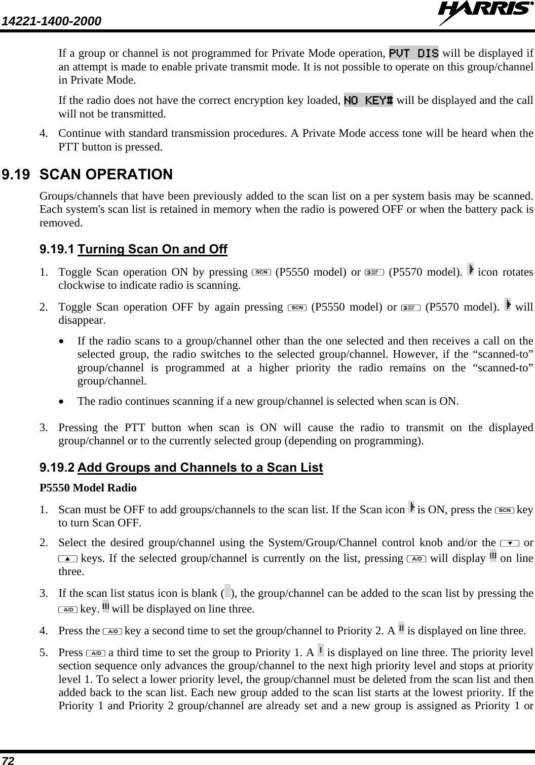
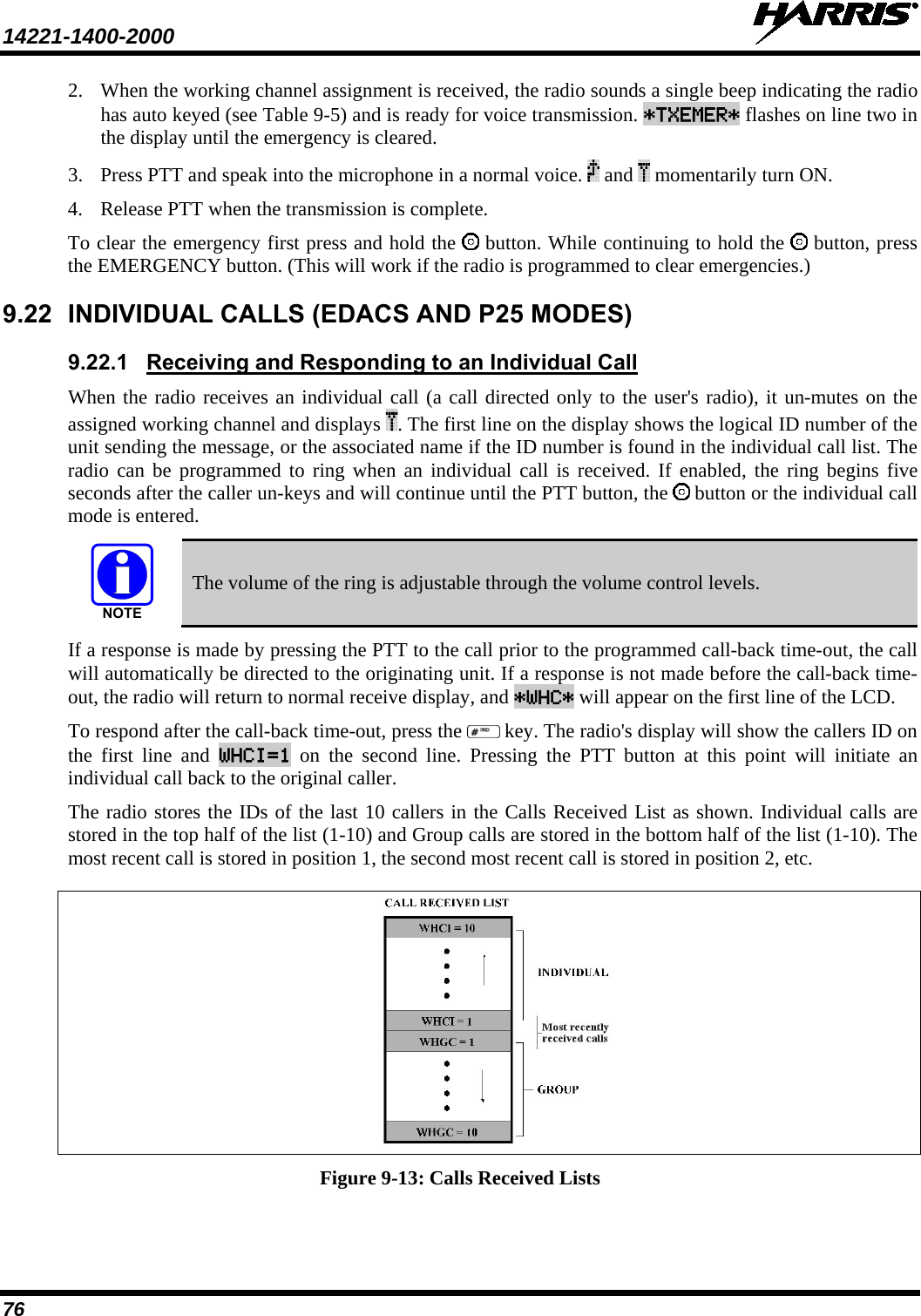
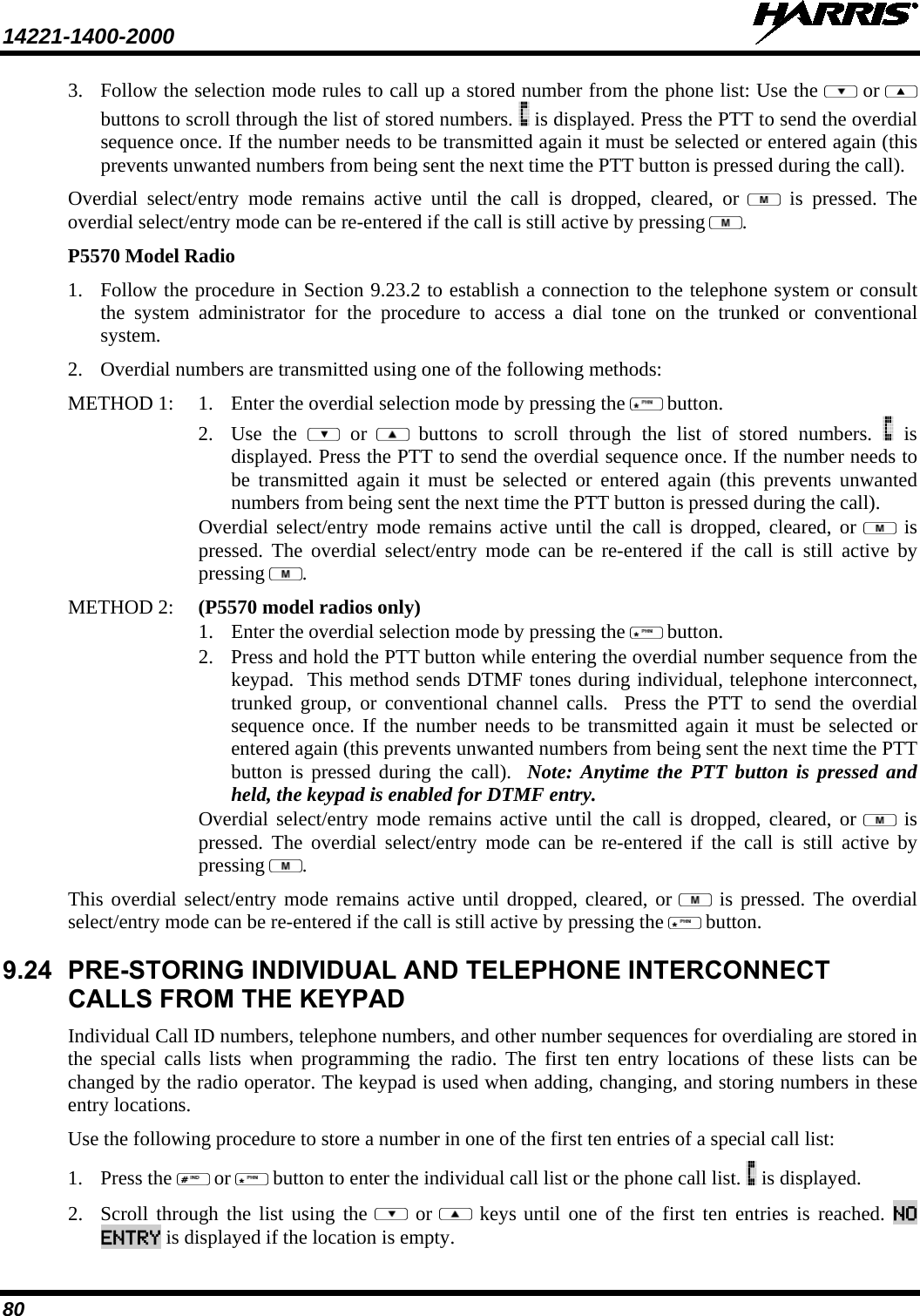
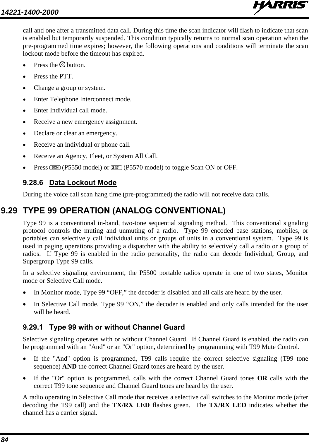
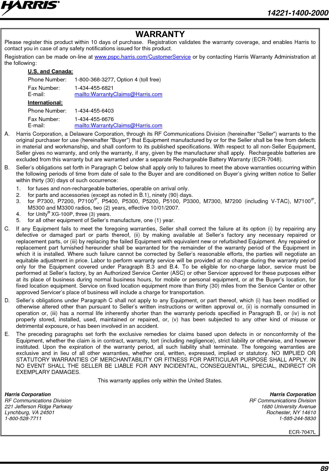
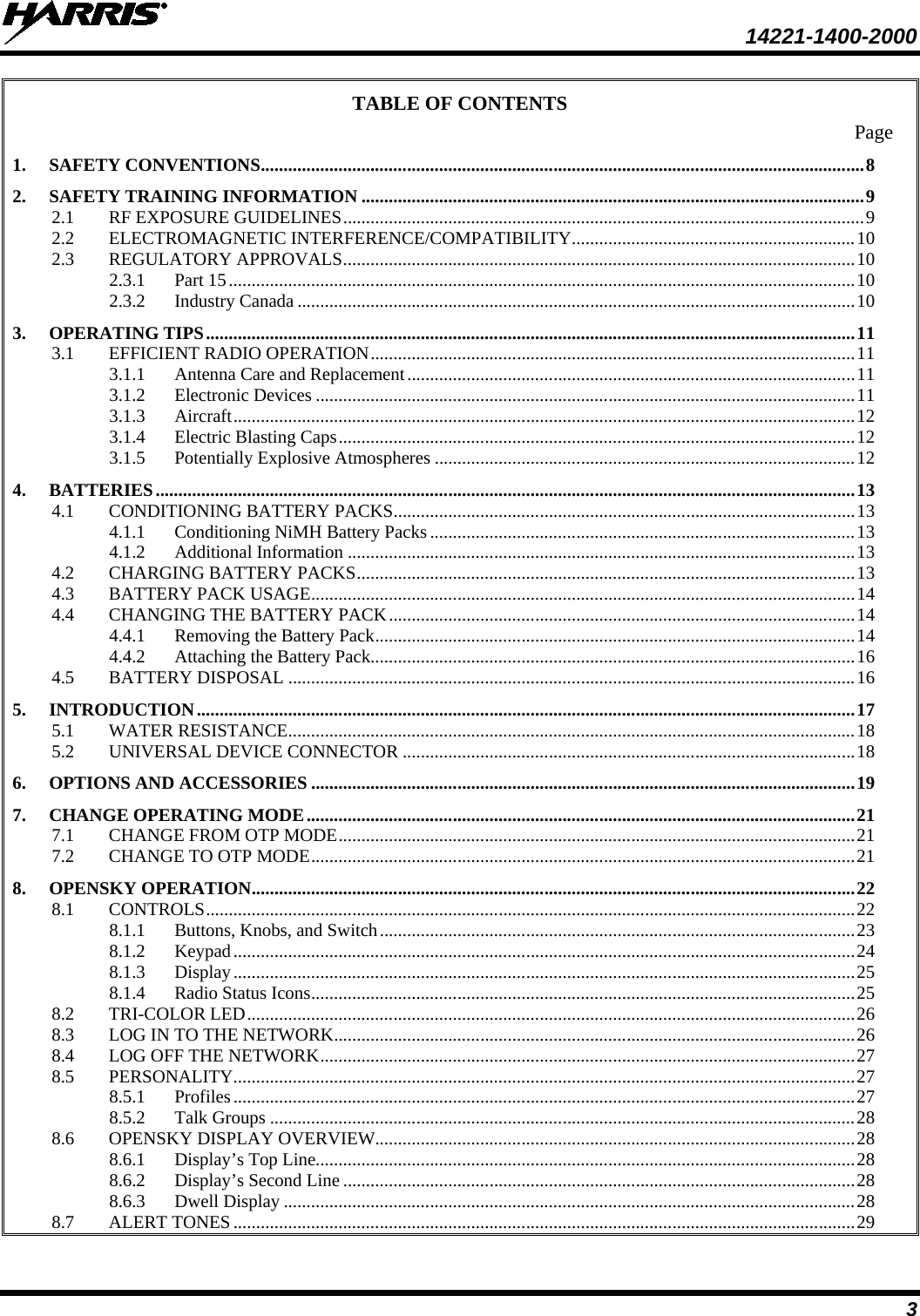
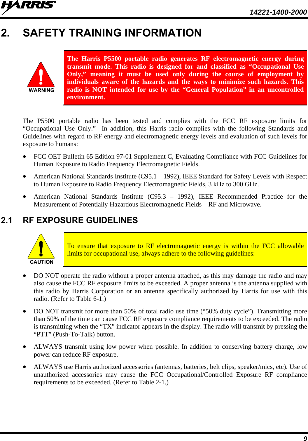
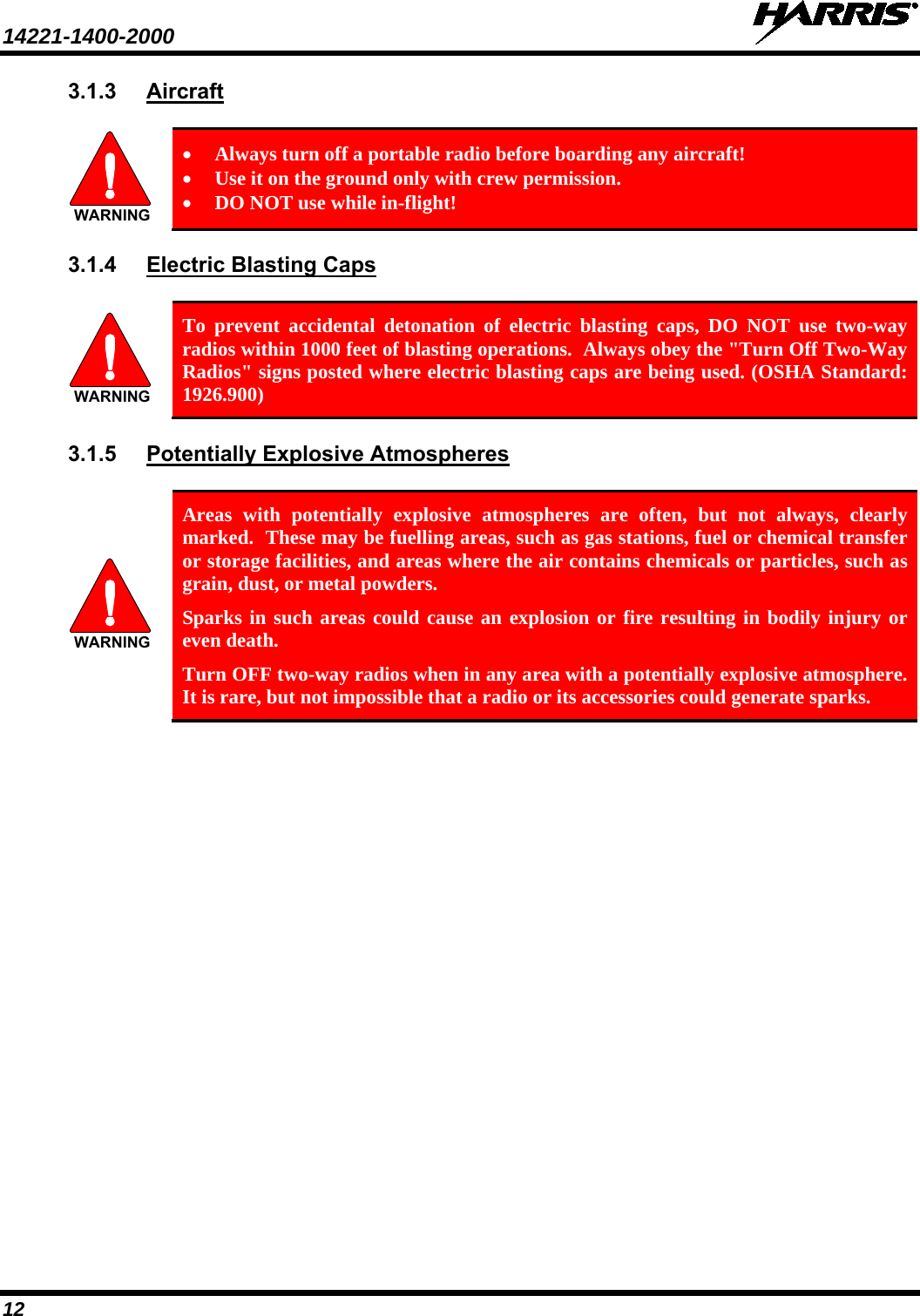
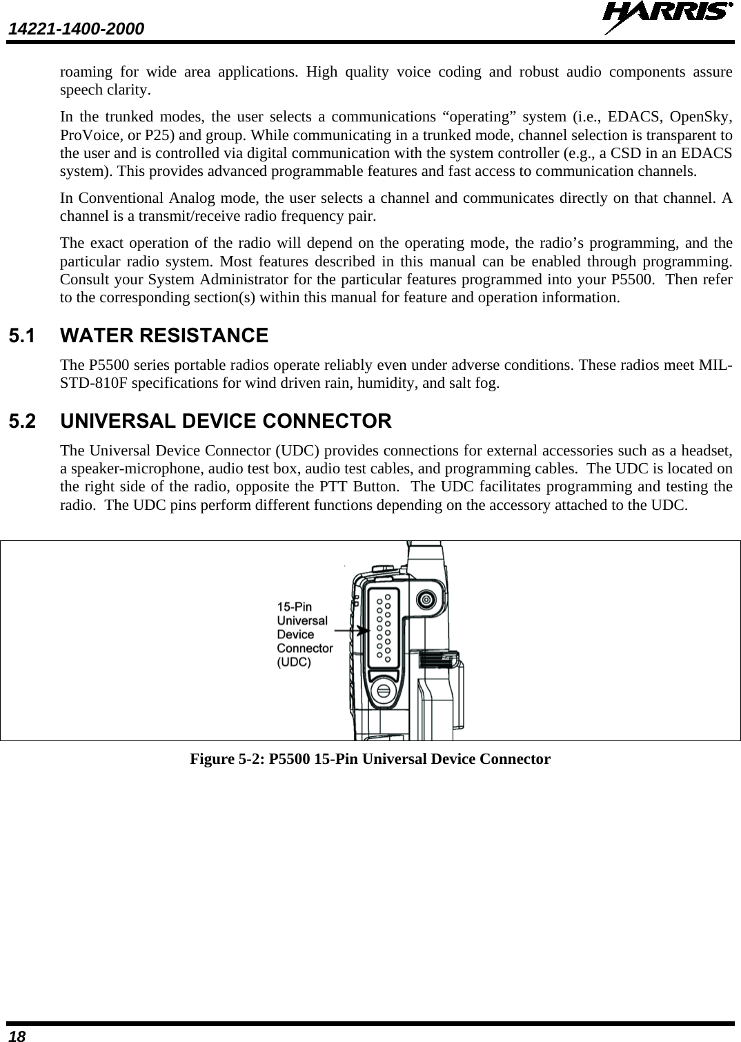
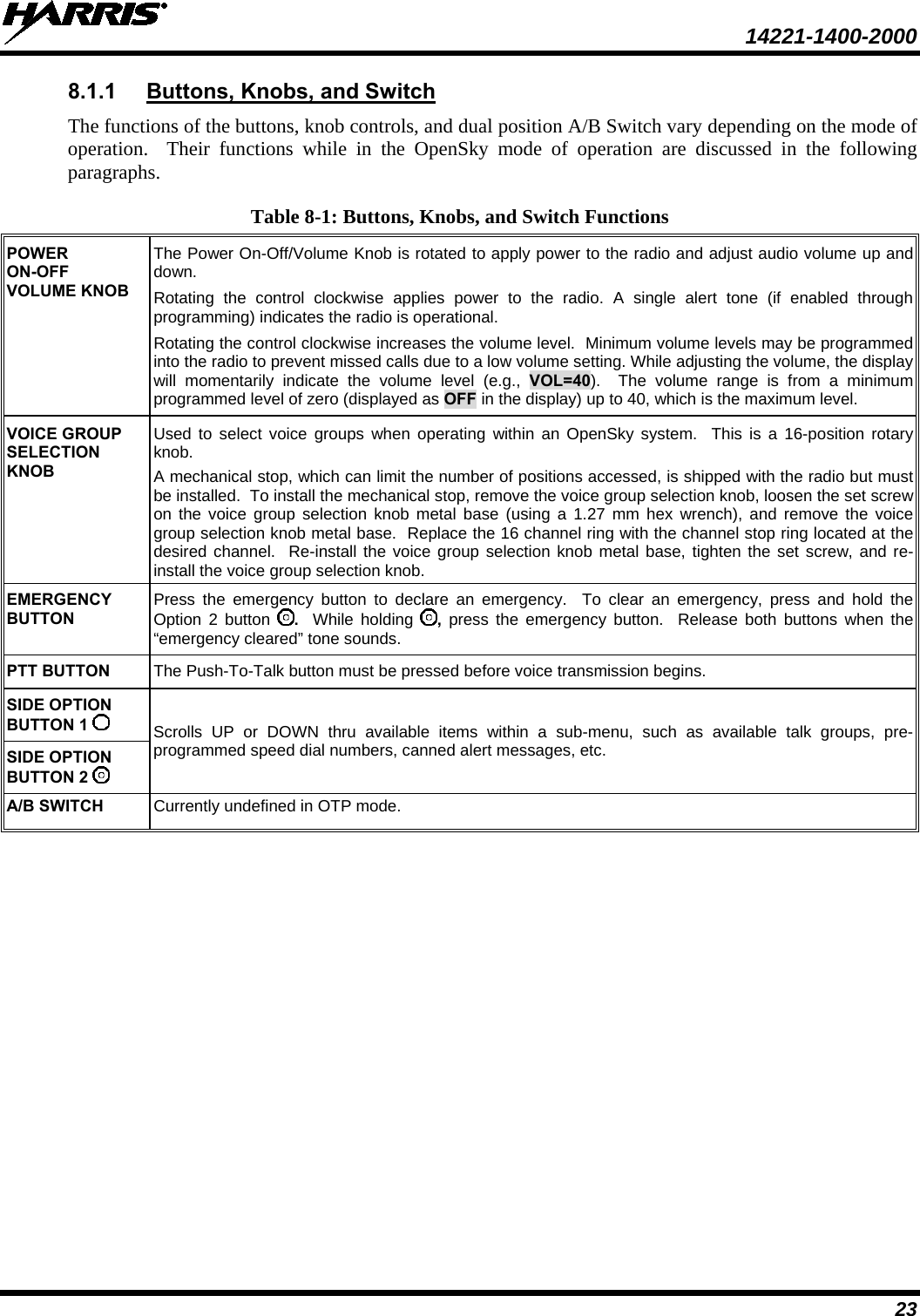
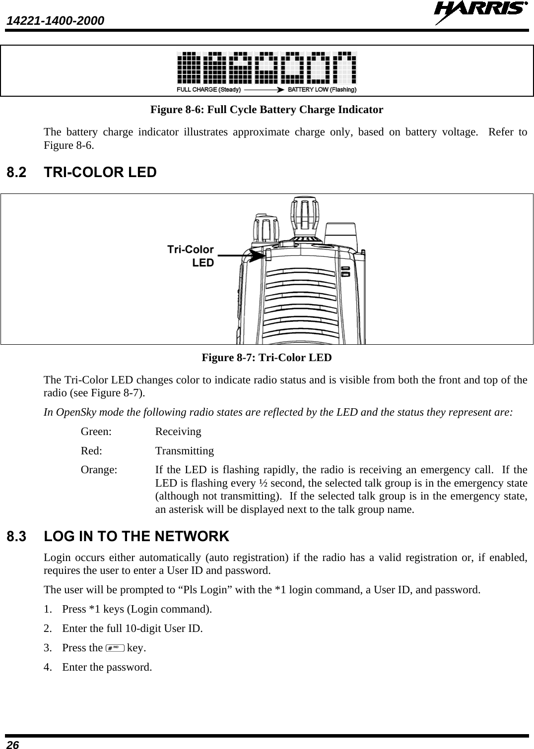
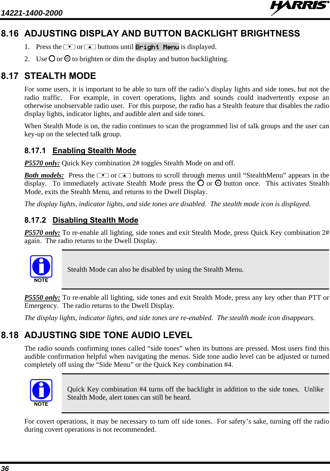
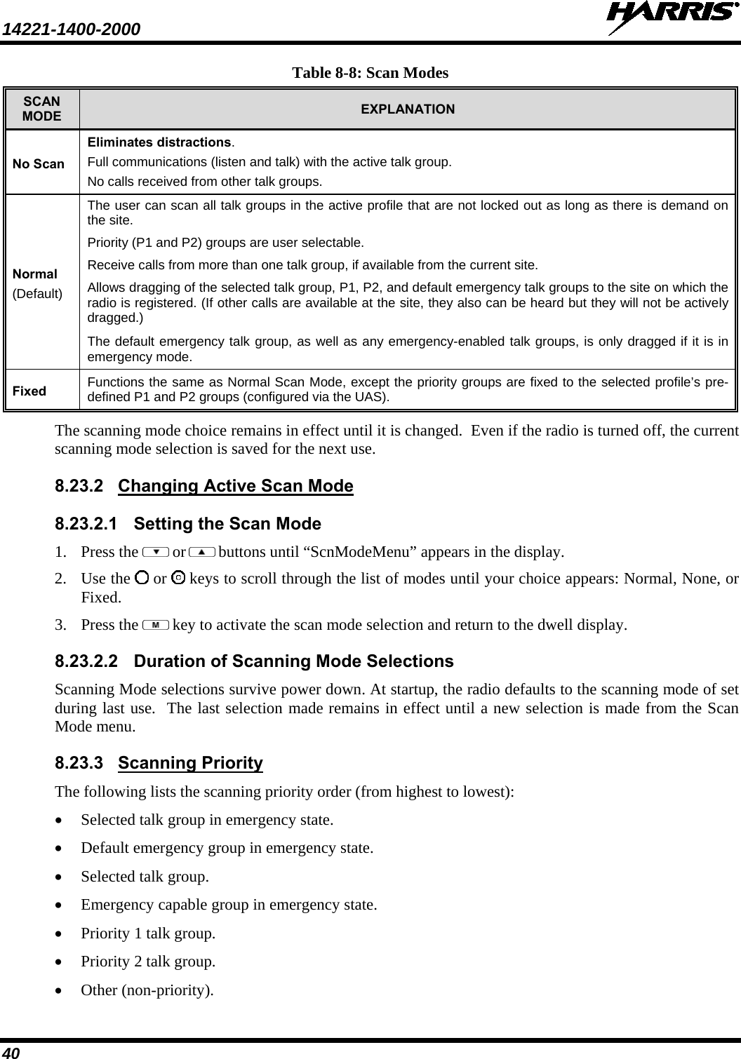
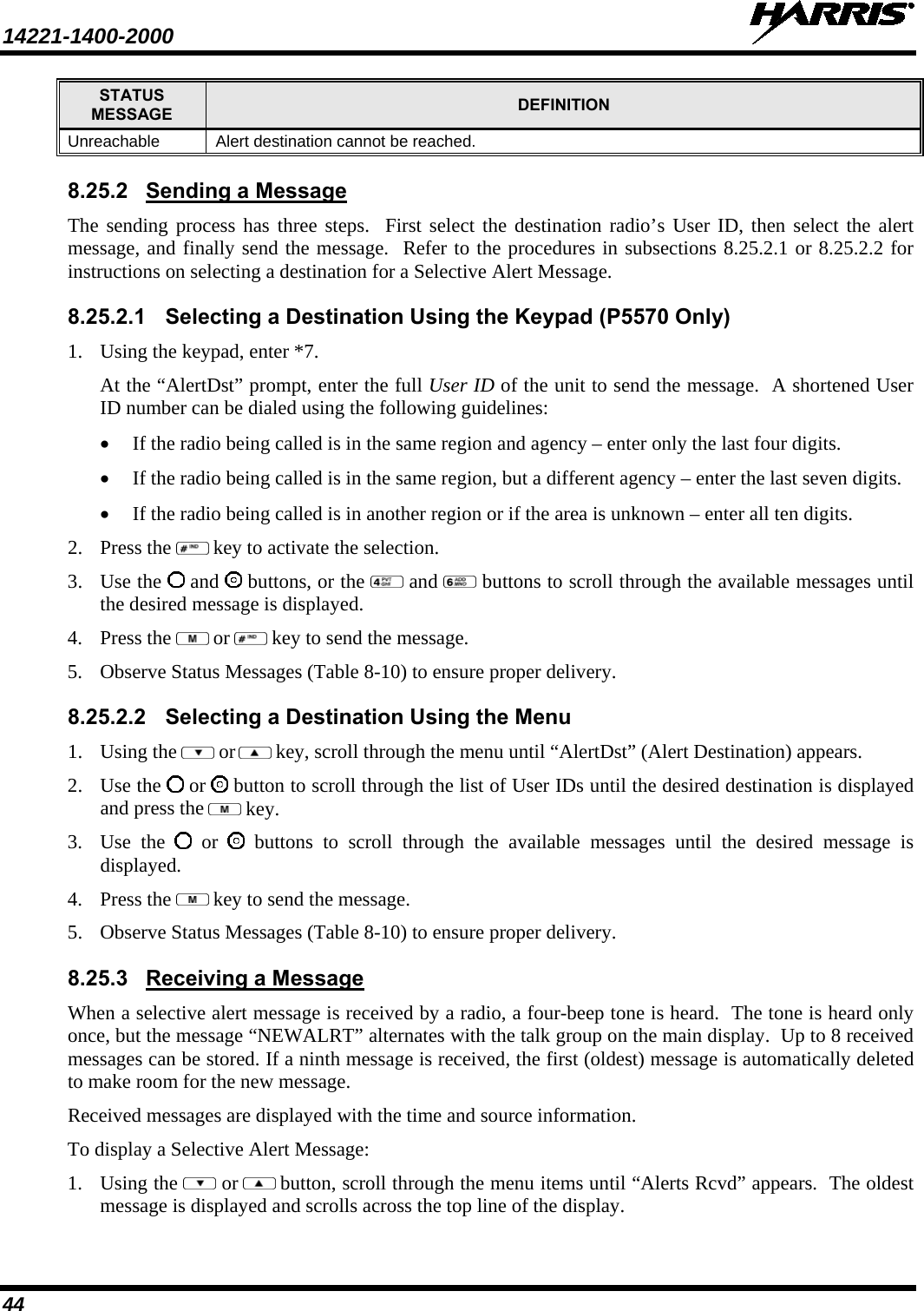
![14221-1400-2000 34 8.10 KEYPAD FUNCTION COMMANDS (P5570 ONLY) To perform a command from the keypad, use the keypad commands in Table 8-6. Table 8-6: Keypad Function Commands COMMANDS FUNCTION *0 Log-off command: *0## (logs the user off the system). See Section 8.4 for additional information. *1 Log-in command: *1<User ID> # <Password> ## (required for encryption). See Section 8.1.3 for additional information. *2 Status Message: *2 <0...9> #. *4 Enter Scene of Incident Mode (SOI) on specified channel and band: *4<LC>#<Band># where LC is the channel number that is being used as a SOI repeater and band is the number assigned to each frequency band. For example, if LC 25 800 MHz (band 0) is being used for SOI, then enter *4,25,#,0,#. Exit SOI Mode with *40# *5 RTT Message: *5 <0...9> #. *7 Initiate Selective Alert command: *7<Target ID>#[Choose Message]#. See Section 8.25 for additional information. *8 Radio-to-Radio Call command: *8<Selective call number>#(PTT to dial). *9 Public Switched Telephone Network (PSTN) Call command: *9 <telephone number>#(PTT to dial) See Section 8.26 for additional information. *32 Begin Manual Encryption command: *32<Pre-determined Encryption Key># 1-16 digit encryption key for 128 bit encryption; 17-32 digit encryption key for 256 bit encryption. *33 End Manual Encryption command: *33# *61 Initiate XCOV Mode: Extended coverage for individual users. *62 Initiate XCOV-TG Mode: Extended coverage for talk groups. *63 Initiate XCOV-PROF Mode command: *63#. *60 Exit XCOV or XCOV-TG Mode: Returns to the normal mode. 8.11 QUICK KEYS (P5570 ONLY) Quick Keys are a two-button sequence that provides the user with quick access to certain menu items. Quick Keys function as a toggle for these menu items. Table 8-7: Quick Key Sequence QUICK KEYS FUNCTION 1# Transition to ECP Mode If ECP code is not loaded in the radio, “No App” appears in the display. 2# Toggles Stealth Mode On/Off 3# Toggles Scan Mode On/Off (Normal/Fixed, see details below) • If the Scan Mode is Normal when the Scan Mode is toggled Off, the Scan Mode will be Normal when toggled On again. • If the Scan Mode is Fixed when the Scan Mode is toggled Off, the Scan Mode will be Fixed when scan mode is toggled On again. • If the Scan Mode is Off when the radio boots up, the Scan Mode will be Normal when Scan Mode is toggled On.](https://usermanual.wiki/HARRIS/TR-0066-E/User-Guide-1537752-Page-35.png)
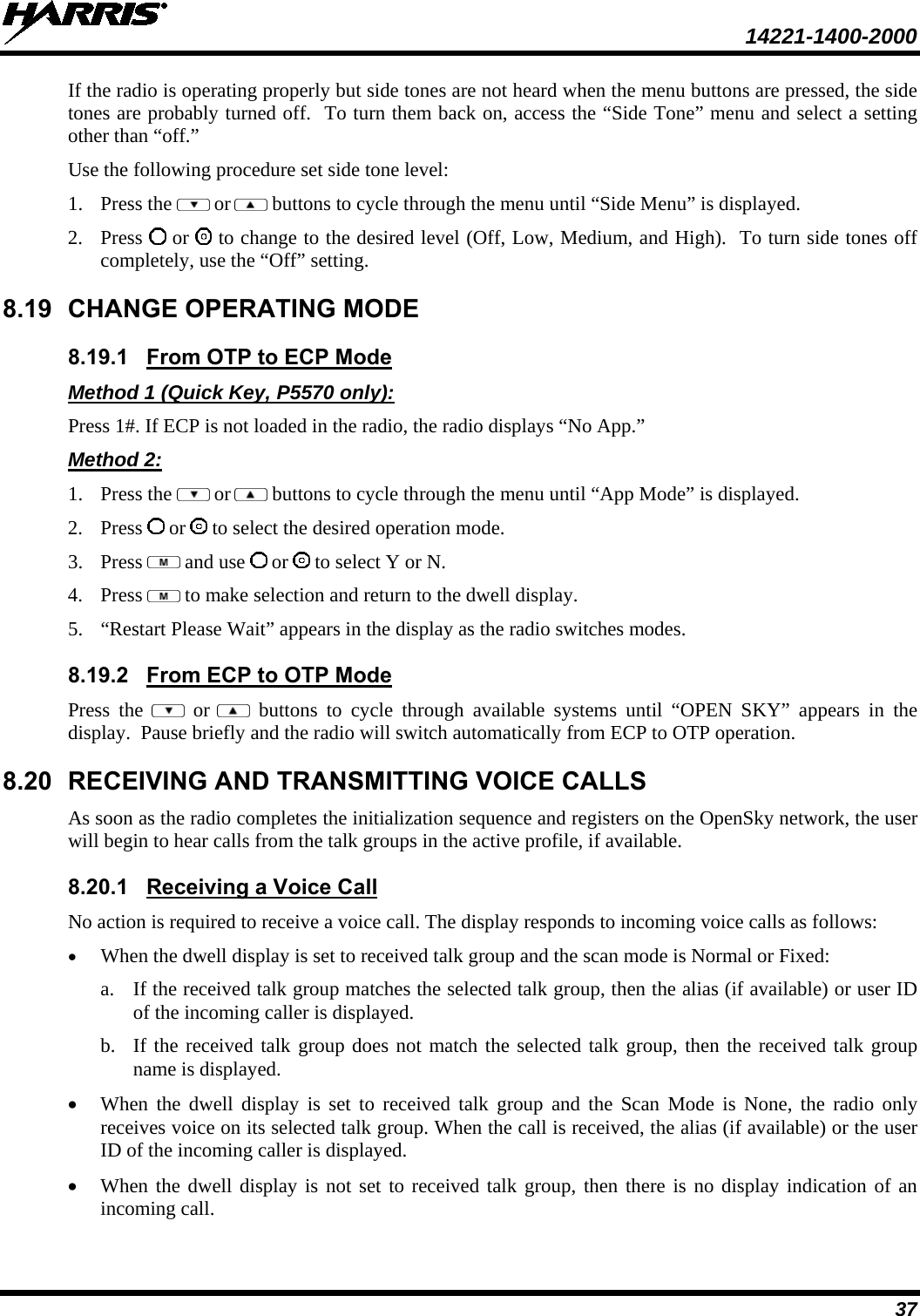
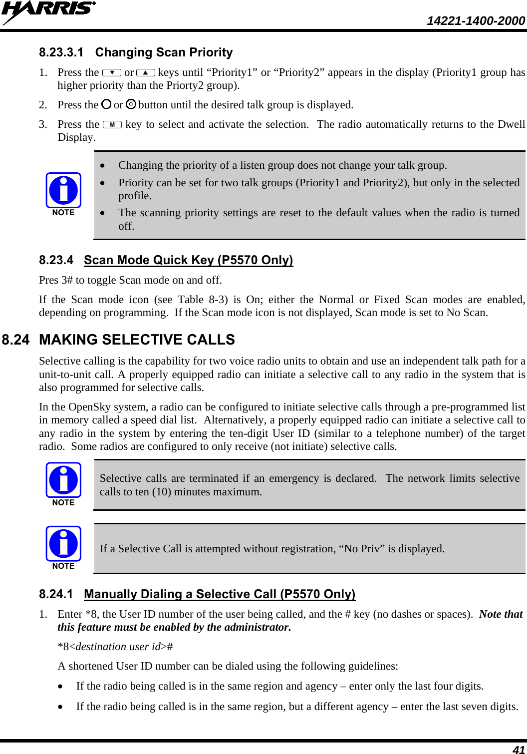
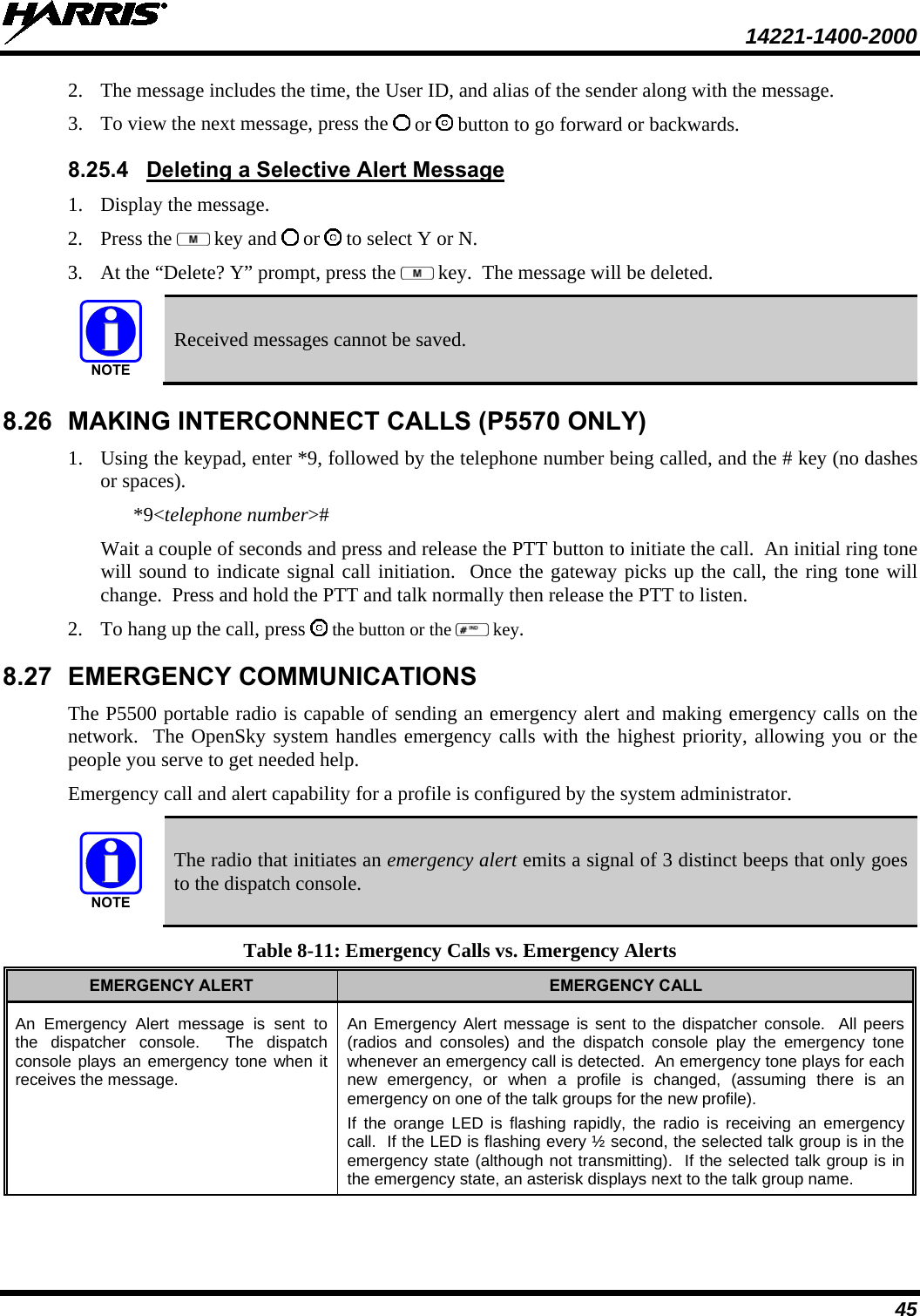

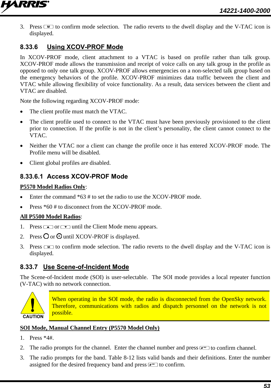
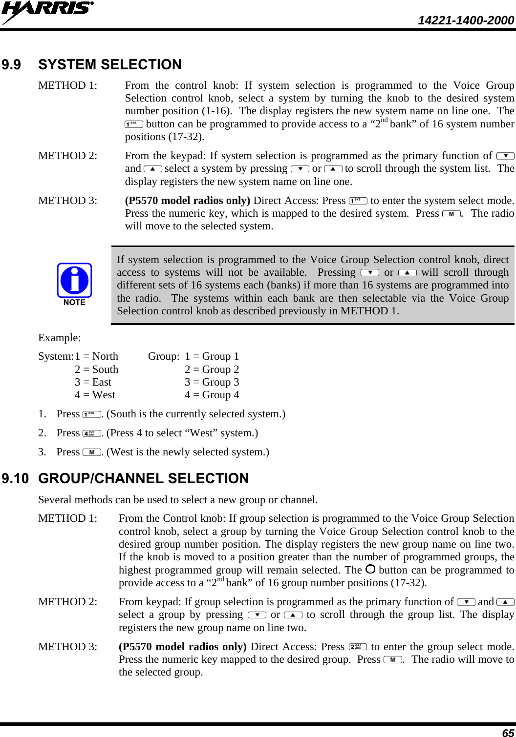
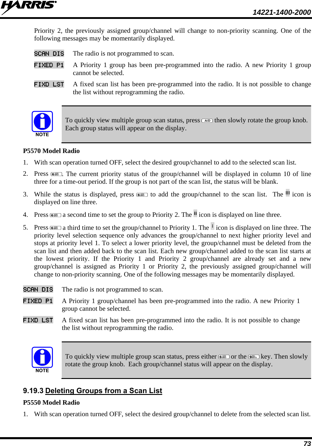
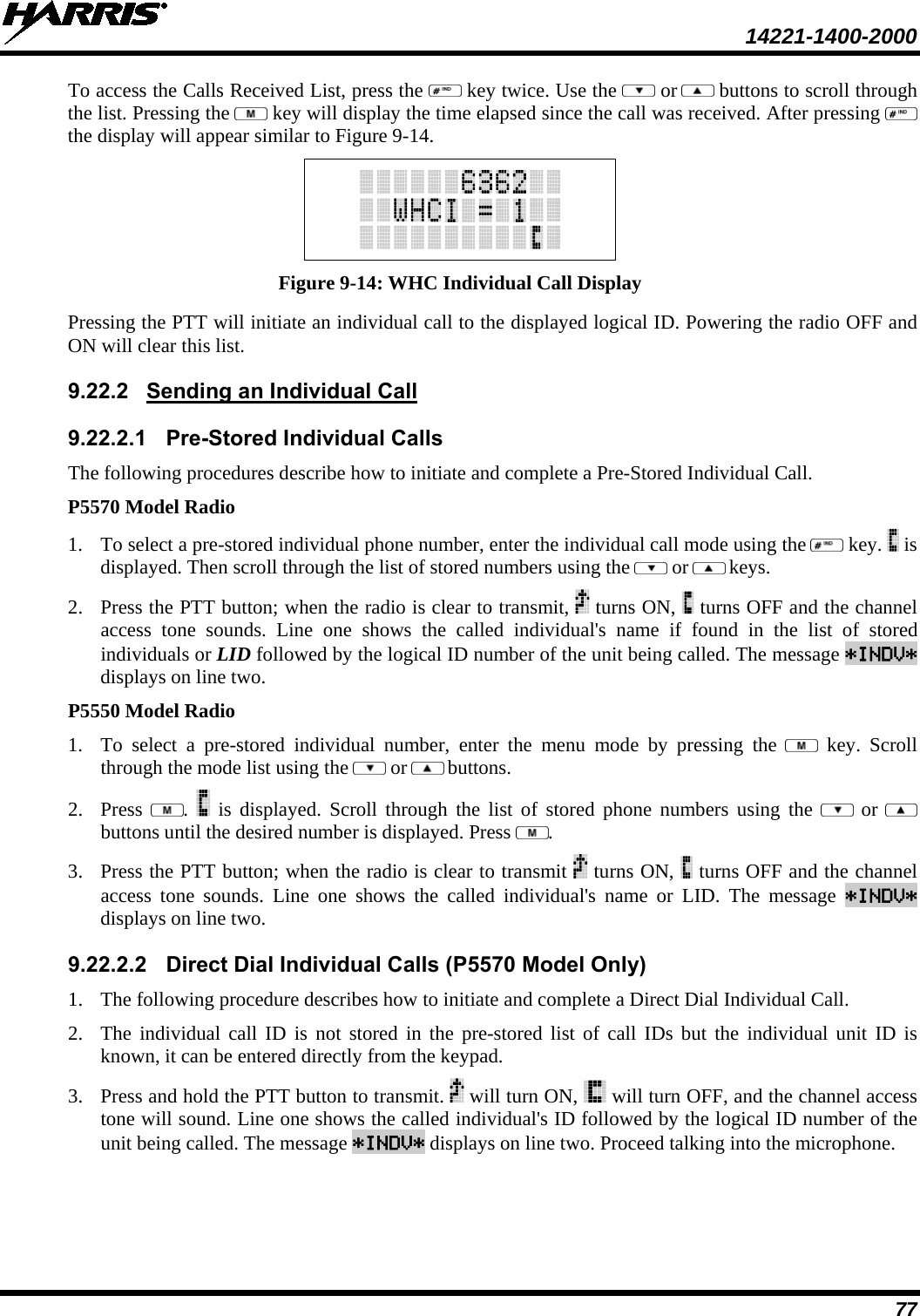
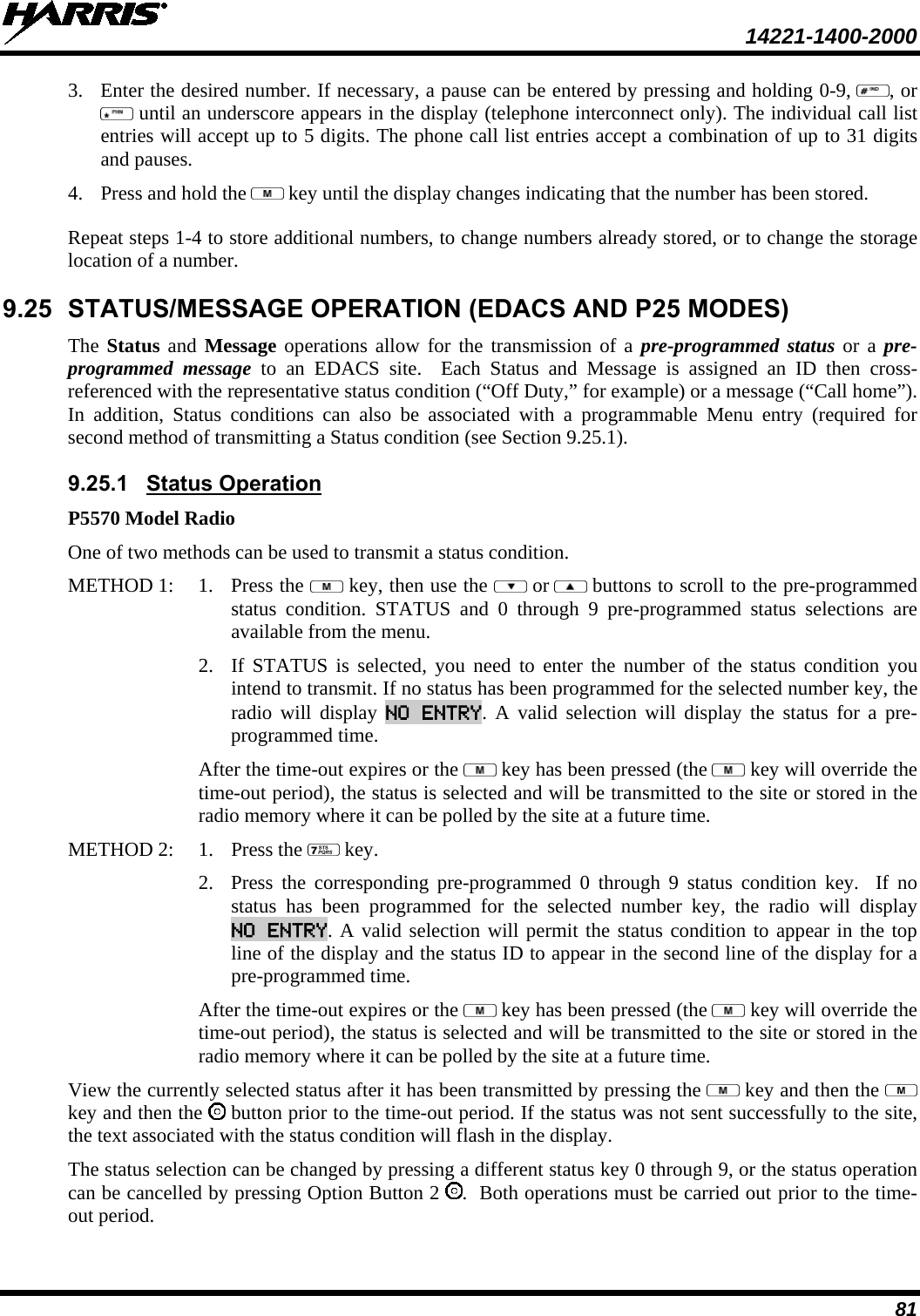
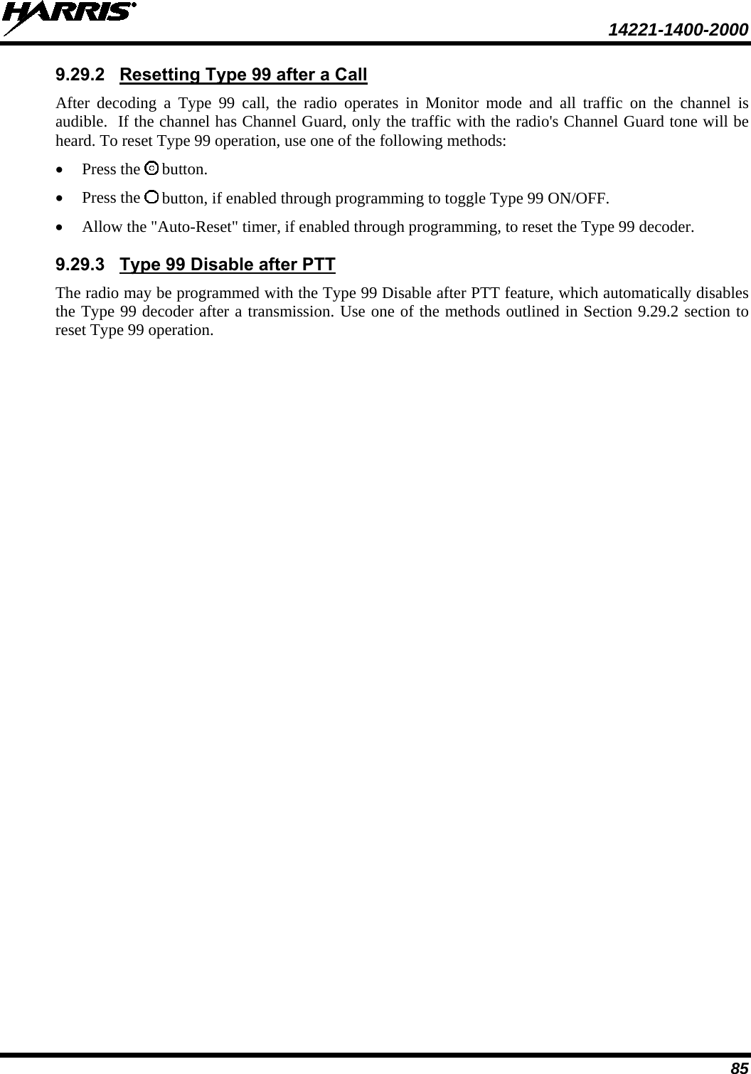
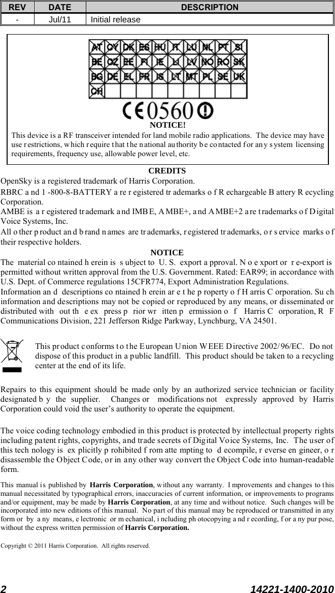
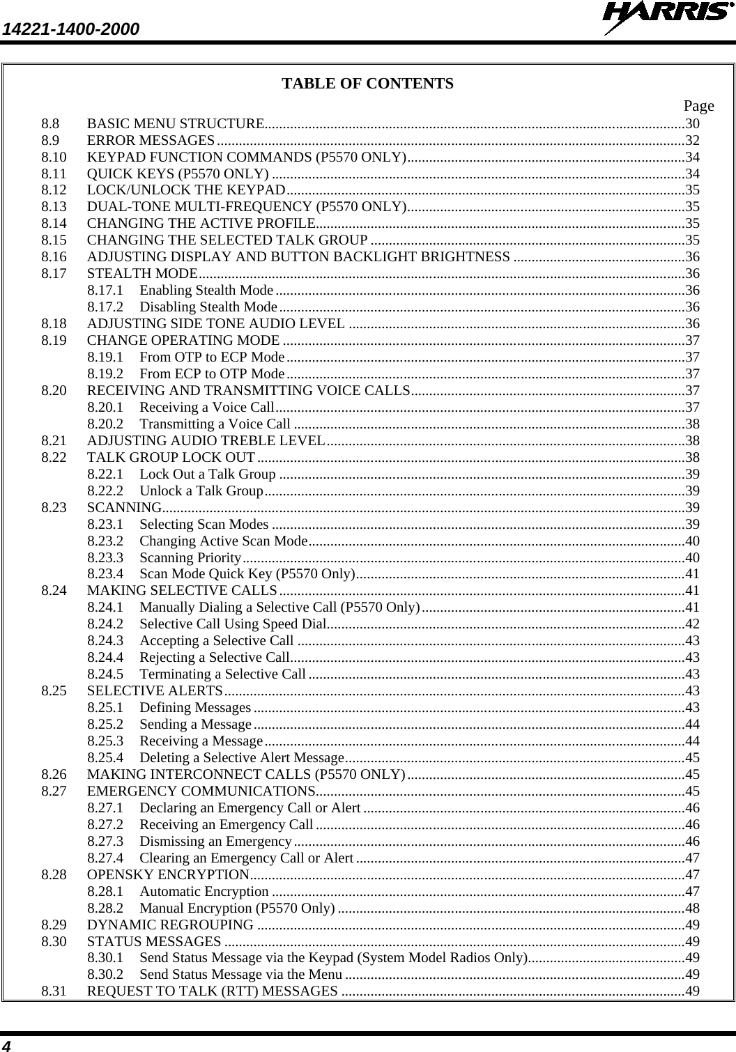
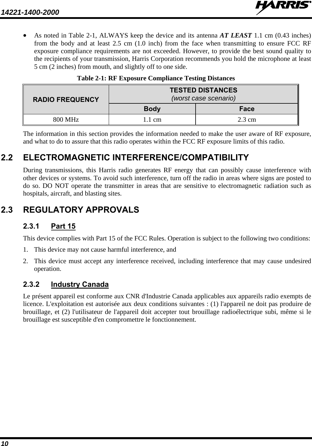
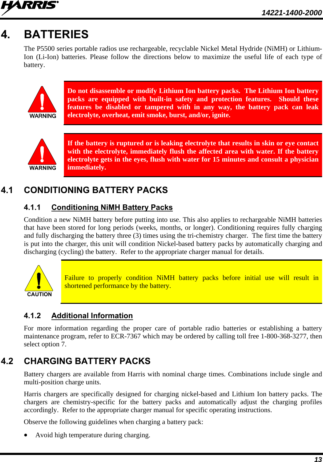
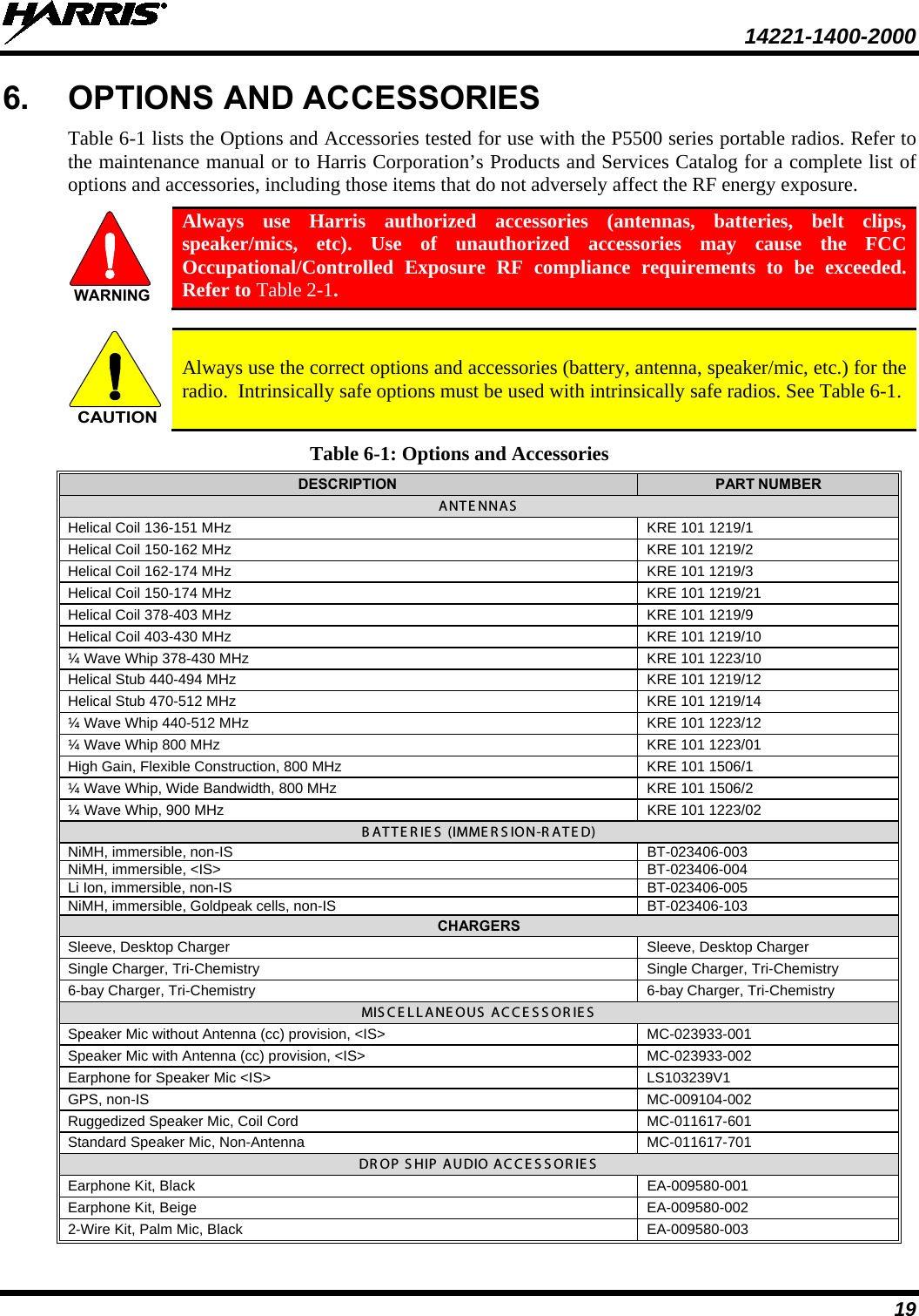
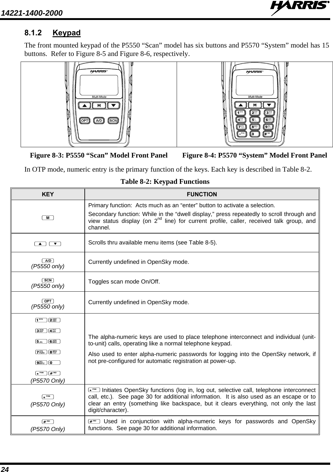
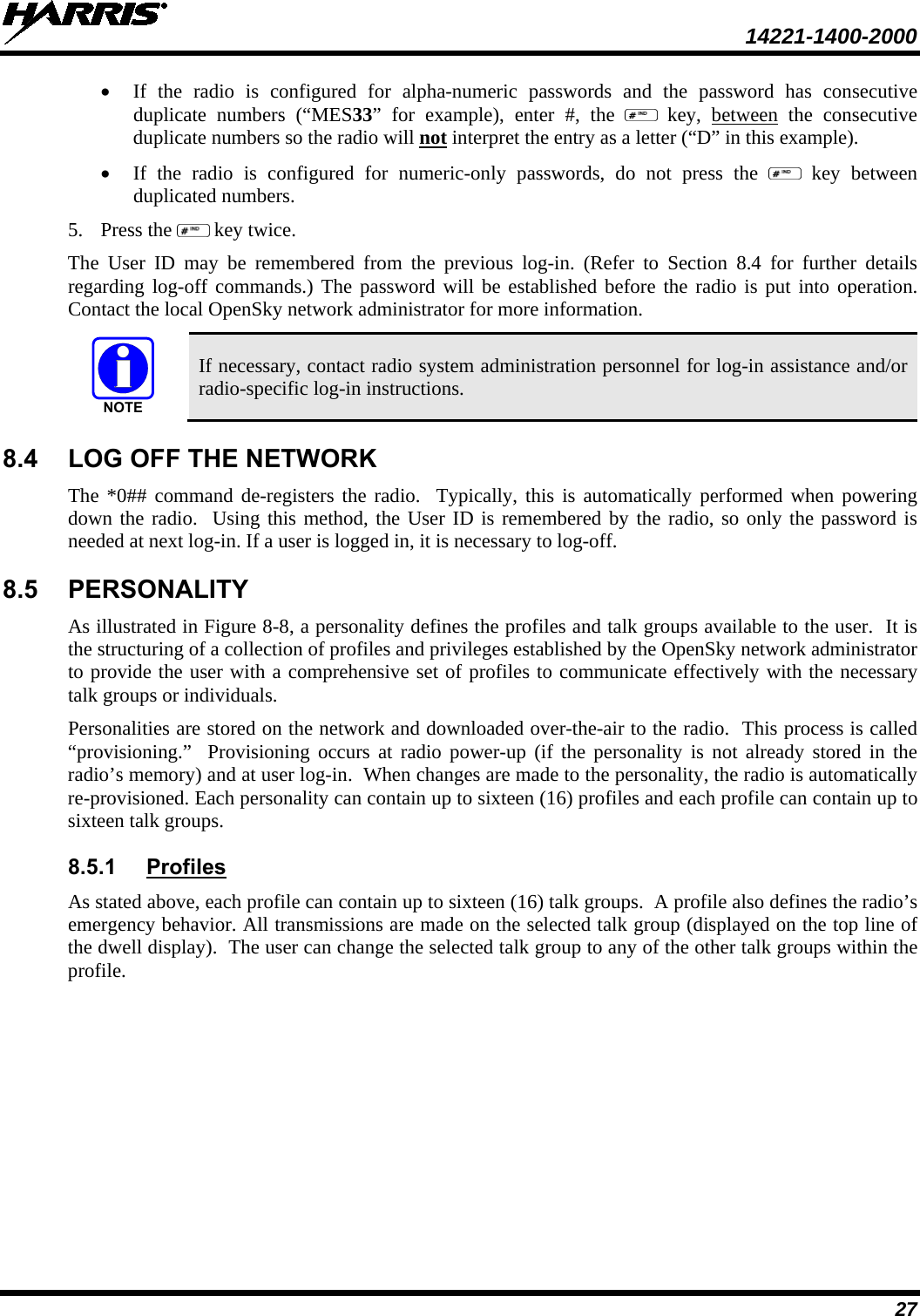
![14221-1400-2000 50 8.31.1 Send RTT Message via the Keypad (System Model Radios Only) 1. Press *5 <0…9> # on the keypad. The key associated with the RTT message (0-9) is configured via programming. 2. This message is displayed on the first line of the display when the key is pressed until another key is pressed. • If no message has been configured, “No Message” is displayed. • If a message is not assigned to the key, “No Entry” is displayed for the keypad sequence. 3. The # key terminates the keypad sequence and sends the currently selected RTT message. If no message has been configured or no message is associated with the key, no message is sent and an error tone is played. Press the * key to cancel the keypad sequence. 8.31.2 Send RTT Message via the Menu 1. Press or until “RTT Msg” appears and press . If no message has been configured, “No Message” is displayed. 2. Use or to select the message. The configured RTT message is displayed on the 1st line of the display. 3. Press the button to send the selected message. If no message has been configured, no message is sent and an error tone sounds. Press or to cancel RTT message selection. 8.32 GPS COORDINATES The radio’s current latitude and longitude coordinates may be displayed using the “GPS” menu. The following procedure assumes a GPS antenna is connected to the radio and it is receiving adequate signals from GPS satellites. 1. Press or until the “GPS” menu appears in the display. Current GPS coordinate latitude and longitude data continuously scrolls in the top line of the display in a degrees:minutes:seconds format. 2. Press or to change to another menu. NOTE If the internal GPS receiver’s data is expired (30 minutes or more) or unavailable, the radio uses the serving base station’s coordinates [GPS (Site) is displayed]. The GPS Menu will also indicate if the data is aged (2 minutes or more) [GPS (Aged) is displayed]. 8.33 V-TAC OPERATION 8.33.1 Extended Coverage Modes (XCOV, XCOV-TG, and XCOV-PROF) In addition to all standard portable radio operating capabilities, Extended Coverage adds the V-TAC’s bridging (vehicular repeat) functionality for accessing the OpenSky radio network. Each portable radio connected to the V-TAC using Extended Coverage is considered a “client” on the V-TAC. Extended Coverage benefits portable radio users since it allows them to get network connectivity using the V-TAC’s higher transmit output power and better antenna system.](https://usermanual.wiki/HARRIS/TR-0066-E/User-Guide-1537752-Page-51.png)